

Page 1
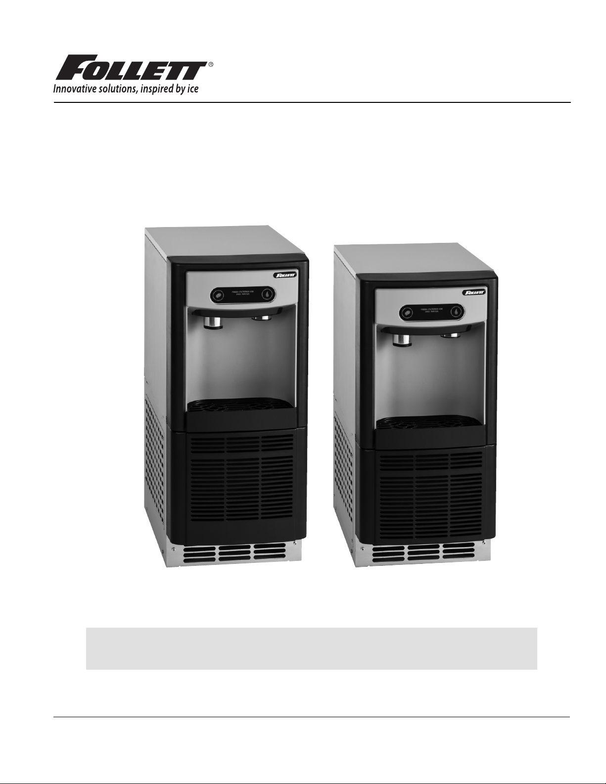
Undercounter Ice and Water Dispenser
®
with Chewblet
7UC100A, 7UD100A
Installation, Operation and Service Manual
Serial numbers E01087 and above
Ice Machine
7UC100A
Following installation, please forward this manual
totheappropriate operations person.
801 Church Lane • Easton, PA 18040, USA
Toll free (877) 612-5086 • +1 (610) 252-7301
www.follettice.com
7UD100A
Order parts online:
www.follettice.com
00966879R07
Page 2
2 Undercounter Dispenser and Ice machine 7UC100A/7UD100A
Page 3

Contents
Welcome . . . . . . . . . . . . . . . . . . . . . . . . . . . . . . . . . . . . . . . . . . . . . . . . . . . . . . . . . . . . . . . . . . . . . . . . . . . . . . . . . . . . . 4
Before You Begin . . . . . . . . . . . . . . . . . . . . . . . . . . . . . . . . . . . . . . . . . . . . . . . . . . . . . . . . . . . . . . . . . . . . . . . . . . . . . . 4
Important Safety Information . . . . . . . . . . . . . . . . . . . . . . . . . . . . . . . . . . . . . . . . . . . . . . . . . . . . . . . . . . . . . . . . . . . . 4
Speci cations . . . . . . . . . . . . . . . . . . . . . . . . . . . . . . . . . . . . . . . . . . . . . . . . . . . . . . . . . . . . . . . . . . . . . . . . . . . . . . . . 5
Dimensions . . . . . . . . . . . . . . . . . . . . . . . . . . . . . . . . . . . . . . . . . . . . . . . . . . . . . . . . . . . . . . . . . . . . . . . . . . . . . . . . 5
Ambient Information . . . . . . . . . . . . . . . . . . . . . . . . . . . . . . . . . . . . . . . . . . . . . . . . . . . . . . . . . . . . . . . . . . . . . . . . . 5
Plumbing . . . . . . . . . . . . . . . . . . . . . . . . . . . . . . . . . . . . . . . . . . . . . . . . . . . . . . . . . . . . . . . . . . . . . . . . . . . . . . . . . . 5
Water . . . . . . . . . . . . . . . . . . . . . . . . . . . . . . . . . . . . . . . . . . . . . . . . . . . . . . . . . . . . . . . . . . . . . . . . . . . . . . . . . . . . 5
Clearances . . . . . . . . . . . . . . . . . . . . . . . . . . . . . . . . . . . . . . . . . . . . . . . . . . . . . . . . . . . . . . . . . . . . . . . . . . . . . . . . 5
Electrical . . . . . . . . . . . . . . . . . . . . . . . . . . . . . . . . . . . . . . . . . . . . . . . . . . . . . . . . . . . . . . . . . . . . . . . . . . . . . . . . . . 5
Refrigeration . . . . . . . . . . . . . . . . . . . . . . . . . . . . . . . . . . . . . . . . . . . . . . . . . . . . . . . . . . . . . . . . . . . . . . . . . . . . . . . 5
Heat Rejection . . . . . . . . . . . . . . . . . . . . . . . . . . . . . . . . . . . . . . . . . . . . . . . . . . . . . . . . . . . . . . . . . . . . . . . . . . . . . 5
Detailed Drawing . . . . . . . . . . . . . . . . . . . . . . . . . . . . . . . . . . . . . . . . . . . . . . . . . . . . . . . . . . . . . . . . . . . . . . . . . . . 6
Installation . . . . . . . . . . . . . . . . . . . . . . . . . . . . . . . . . . . . . . . . . . . . . . . . . . . . . . . . . . . . . . . . . . . . . . . . . . . . . . . . . . . 7
Maintenance/Cleaning Mode . . . . . . . . . . . . . . . . . . . . . . . . . . . . . . . . . . . . . . . . . . . . . . . . . . . . . . . . . . . . . . . . . . . . 9
Accessing Internal Components . . . . . . . . . . . . . . . . . . . . . . . . . . . . . . . . . . . . . . . . . . . . . . . . . . . . . . . . . . . . . . . . . 9
Filter Display Indicator Activation . . . . . . . . . . . . . . . . . . . . . . . . . . . . . . . . . . . . . . . . . . . . . . . . . . . . . . . . . . . . . . . 10
Cleaning and Sanitizing . . . . . . . . . . . . . . . . . . . . . . . . . . . . . . . . . . . . . . . . . . . . . . . . . . . . . . . . . . . . . . . . . . . . . . . 11
Service . . . . . . . . . . . . . . . . . . . . . . . . . . . . . . . . . . . . . . . . . . . . . . . . . . . . . . . . . . . . . . . . . . . . . . . . . . . . . . . . . . . . . 12
LED Indicator Description . . . . . . . . . . . . . . . . . . . . . . . . . . . . . . . . . . . . . . . . . . . . . . . . . . . . . . . . . . . . . . . . . . . . 12
Evaporator Disassembly . . . . . . . . . . . . . . . . . . . . . . . . . . . . . . . . . . . . . . . . . . . . . . . . . . . . . . . . . . . . . . . . . . . . . 13
Evaporator Assembly . . . . . . . . . . . . . . . . . . . . . . . . . . . . . . . . . . . . . . . . . . . . . . . . . . . . . . . . . . . . . . . . . . . . . . . 16
Water Feed Schematic . . . . . . . . . . . . . . . . . . . . . . . . . . . . . . . . . . . . . . . . . . . . . . . . . . . . . . . . . . . . . . . . . . . . . . 20
Bin Melt Water/Evaporator Feed/Clean Out System Schematic . . . . . . . . . . . . . . . . . . . . . . . . . . . . . . . . . . . . . . 21
Vent System Schematic . . . . . . . . . . . . . . . . . . . . . . . . . . . . . . . . . . . . . . . . . . . . . . . . . . . . . . . . . . . . . . . . . . . . . 21
Refrigeration Schematic . . . . . . . . . . . . . . . . . . . . . . . . . . . . . . . . . . . . . . . . . . . . . . . . . . . . . . . . . . . . . . . . . . . . . 22
Condenser Fan Motor Removal . . . . . . . . . . . . . . . . . . . . . . . . . . . . . . . . . . . . . . . . . . . . . . . . . . . . . . . . . . . . . . . 23
User Interface Display Identi cation . . . . . . . . . . . . . . . . . . . . . . . . . . . . . . . . . . . . . . . . . . . . . . . . . . . . . . . . . . . . 24
Electrical Wiring Diagram . . . . . . . . . . . . . . . . . . . . . . . . . . . . . . . . . . . . . . . . . . . . . . . . . . . . . . . . . . . . . . . . . . . . 25
Parts . . . . . . . . . . . . . . . . . . . . . . . . . . . . . . . . . . . . . . . . . . . . . . . . . . . . . . . . . . . . . . . . . . . . . . . . . . . . . . . . . . . . . . . 26
Exterior . . . . . . . . . . . . . . . . . . . . . . . . . . . . . . . . . . . . . . . . . . . . . . . . . . . . . . . . . . . . . . . . . . . . . . . . . . . . . . . . . . 26
Interior . . . . . . . . . . . . . . . . . . . . . . . . . . . . . . . . . . . . . . . . . . . . . . . . . . . . . . . . . . . . . . . . . . . . . . . . . . . . . . . . . . . 28
Bin Assembly . . . . . . . . . . . . . . . . . . . . . . . . . . . . . . . . . . . . . . . . . . . . . . . . . . . . . . . . . . . . . . . . . . . . . . . . . . . . . 30
Evaporator Assembly . . . . . . . . . . . . . . . . . . . . . . . . . . . . . . . . . . . . . . . . . . . . . . . . . . . . . . . . . . . . . . . . . . . . . . . 32
Undercounter Dispenser and Ice machine 7UC100A/7UD100A 3
Page 4
Welcome ––––––––––––––––––––––––––––––––––––––––––––––––––––––––––
Follett equipment enjoys a well-deserved reputation for excellent performance, long-term reliability, and outstanding
after-the-sale support. To ensure that this product delivers that same degree of service, we ask that you take a
moment to review this manual before beginning the installation. Should you have any questions or require technical
help at any point, please call our technical service group at (877) 612-5086 or +1 (610) 252-7301.
Before You Begin –––––––––––––––––––––––––––––––––––––––––––––––––––
After uncrating and removing all packing material, inspect the equipment for concealed shipping damage. If damage
is found, immediately notify the shipper and contact Follett Corporation so that we can help in the ling of a claim,
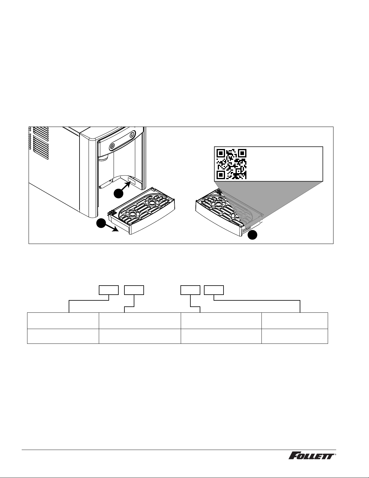
if necessary. If needed, the serial number of your dispenser can be found by removing the drip tray ❶ and locating
the serial number label ❷. A QR Code is located on the right hand side of the drip tray ❸. This code allows you to
access manuals, technical bulletins, and on-line training related to the 7 Series dispensers.
Scan to access technical
documentation or visit
www.follettice.com/7seriesdocs
00981100R00
2
1
3
Check your paperwork to verify that you received the correct dispenser. Follett con guration numbers are designed
to provide information about the type of dispenser you are receiving. The following is an explanation of the different
model numbers.
7UC 100A
Dispenser Storage
Capacity
7 lb UC Undercounter
UD Undercounter - ADA
Con guration Ice machine Capacity Condenser
100 lb per day A Air-cooled
Important Safety Information –––––––––––––––––––––––––––––––––––––––––
Please read and adhere to the following safety information while installing, using, or servicing your Follett 7 Series
Ice Dispenser.
1. Always disconnect power before servicing the dispenser.
2. Ice is slippery. Maintain counters and oors around dispenser in a clean and ice-free condition.
3. Ice is food. Follow the recommended cleaning and sanitizing instructions to maintain cleanliness of
delivered ice.
4 Undercounter Dispenser and Ice machine 7UC100A/7UD100A
Page 5
Speci cations –––––––––––––––––––––––––––––––––––––––––––––––––––––
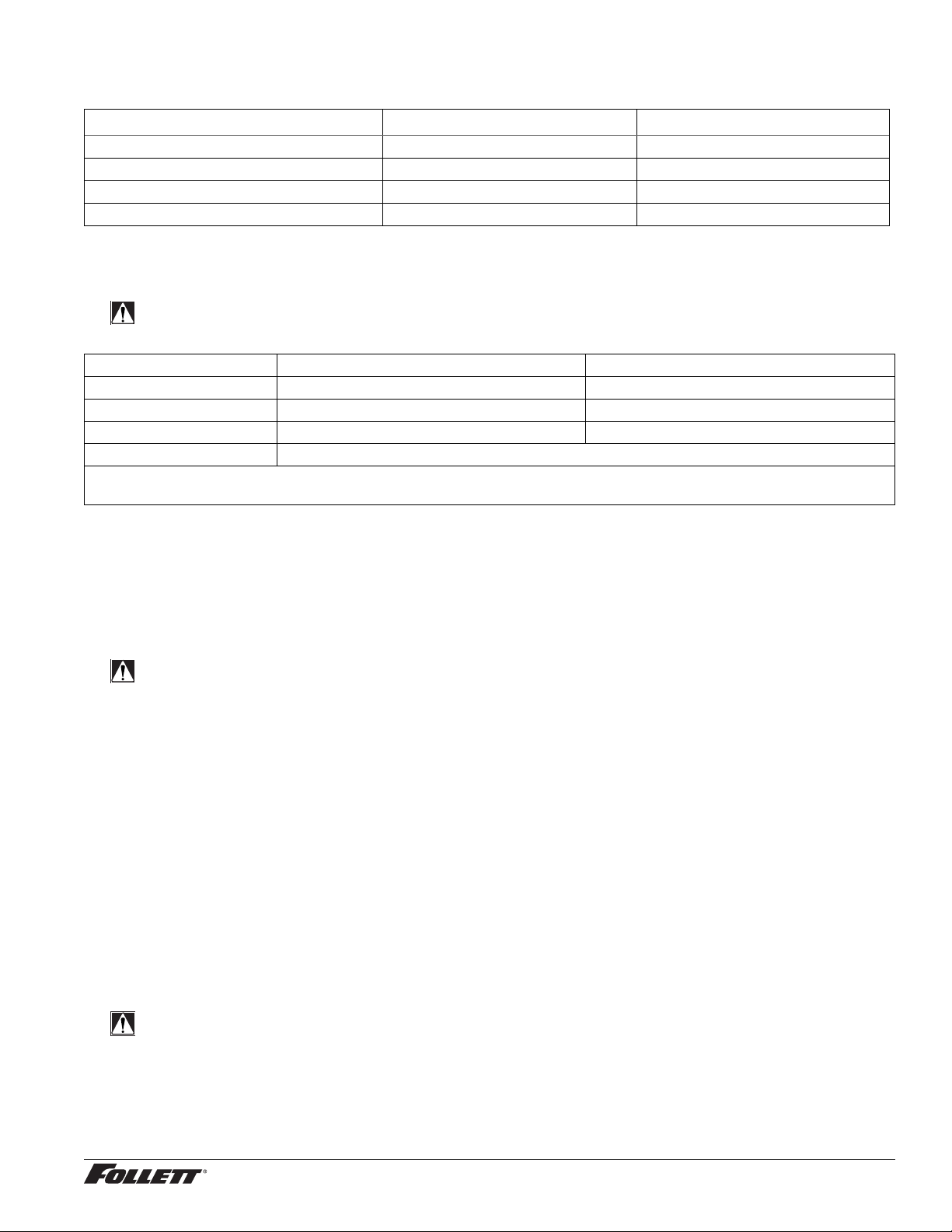
Dimensions
7UC100A 7UD100A
Width 14.55" (370 mm) 14.55" (370 mm)
Depth 22.05" (560 mm) 22.05" (560 mm)
Height 33.50" (851 mm) 31.50" (800 mm)
Unit Shipping Weight 110 lb (50 kg) 110 lb (50 kg)
Ambient Information
CAUTION!
The 7UC100A and 7UD100A are for indoor use only.
Maximum* Minimum*
Air Temperature
Water Temperature 90 F (32.2 C) 40 F (4.5 C)
Water Pressure 70 psi 10 psi
Relative Humidity 55% at 78 F (25.5 C)
* Use outside of these limitations is misuse and will void warranty.
† Best performance is achieved between 80 F (27 C) and 50 F (10 C).
†
100 F (38 C) 50 F (10 C)
Plumbing
§ Water Inlet: 1/4" MPT
§ Optional Drain Accessory Kit (item# 00956375 or 00981977): 1/2" ID tubing
§ Water shut-off recommended within 5 ft. (1.5 m) of dispenser
Water
WARNING!
Connect to potable water supply only.
§ Water Mineral Content:
– TDS: greater than 5 ppm (mg/l) but less than 400 ppm (mg/l)
– Hardness: Less than 200 mg/l (12 gpg)
§ Not recommended for use with softened water
Clearances
§ 3" (77 mm) behind dispenser for electrical and optional drain connection.
§ 6" (153 mm) in front of dispenser for ventilation.
Electrical
§ 115V, 60 Hz, 1 phase, 5A, maximum fuse 15A
§ Connect to dedicated 15A circuit, fuse or breaker
§ Must be grounded - requires 3-prong outlet. Do not remove ground.
Refrigeration
WARNING!
Do not damage the refrigerant circuit. Refrigerant can cause personal injury and/or damage dispenser.
§ Refrigerant R134a – 204 grams (7.2 oz.)
Heat Rejection
§ 1700 BTU/hr (498 W)
Undercounter Dispenser and Ice machine 7UC100A/7UD100A 5
Page 6
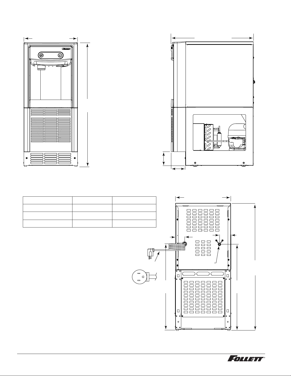
Speci cations (continued) ––––––––––––––––––––––––––––––––––––––––––––––
Detailed Drawing
14.55" (370 mm)
FRONT VIEW
22.05" (560 mm)
A
4.00"
(102 mm)
3.81"
(97 mm)
SIDE VIEW
Dimension
A
B
C
7UC100A 7UD100A (ADA)
33.50” (851 mm)
22.76” (578 mm)
22.69” (576 mm)
31.50” (800 mm)
20.76” (527mm)
20.69” (526 mm)
power cord
NEMA 5-15
right angle
14.55" (370 mm)
2.40"
(61 mm)
1/4" MPT
water inlet
L2
G
L1
B
2.98"
(76 mm)
A
C
6 Undercounter Dispenser and Ice machine 7UC100A/7UD100A
BACK VIEW
Page 7
Installation ––––––––––––––––––––––––––––––––––––––––––––––––––––––––
CAUTION!
No service or maintenance should be performed until the technician has thoroughly read this service
manual. Except for routine cleaning and sanitizing, only quali ed technicians should attempt to service
or maintain this equipment.
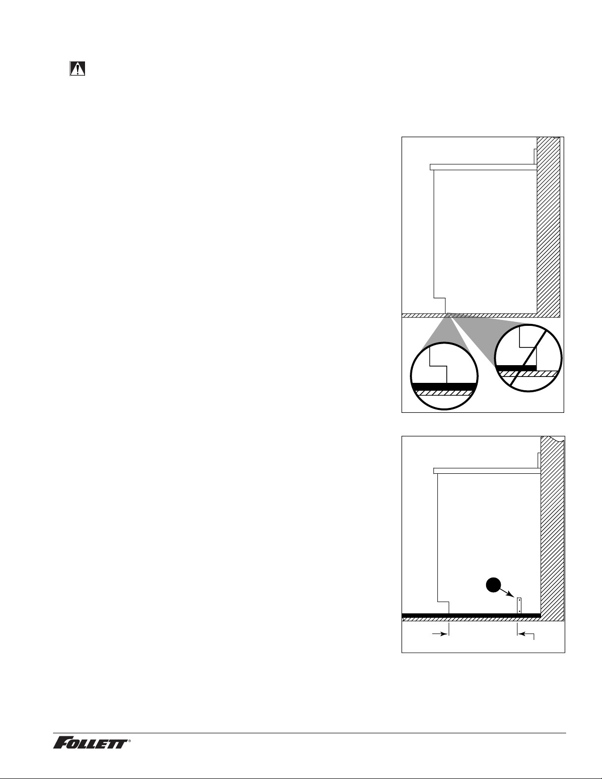
1. Measure to verify that the dispenser will t in the desired location.
A clearance of at least 3" (77 mm) is required behind the dispenser
for the electrical and optional drain connection.
2. Ensure that the nished oor inside the cabinet is ush (level) with
the oor outside the cabinet (Fig. 1). If the cabinet oor is lower
than the nished oor, the cabinet oor must be built up (using
appropriate materials) until it is ush with the nished oor. A ush
oor is required for proper operation and maintenance/service of the
dispenser.
3. Rough-in the electrical service, water line, and optional Drip Tray
Drain Kit*.
Note: The dispenser must be installed such that it can be moved
forward at least 4" (10.16 cm) to allow access to the Bin Lid
Cleaning Spout (Fig. 9.6) for dispenser cleaning and sanitizing.
Take this requirement into consideration during rough-in.
§ Electrical: 115V, single phase, 15A receptacle required. The dispenser
has an integral 8 ft. (2.4 m) cord and plug.
§ Water: supply line (with shut-off valve) connects to the dispenser's 1/4"
MPT inlet.
* The optional Drip Tray Drain Kit (item# 00956375) requires a oor drain
within 15 ft. (4.5 m) of the dispenser. For detailed installation instructions,
please refer to the instructions shipped with the Drip Tray Drain Kit.
Fig. 1
cabinet space
floor
4. Install the angle bracket inside the cabinet,18.15" (461mm) from
the toe kick (Fig. 2.1). The bracket prevents the dispenser from
being located/pushed beyond the recommended cabinet space
depth. Do not attach the bracket to the dispenser.
Fig. 2
1
18.15” (461 mm)
Undercounter Dispenser and Ice machine 7UC100A/7UD100A 7
Page 8
Installation (continued) –––––––––––––––––––––––––––––––––––––––––––––––––
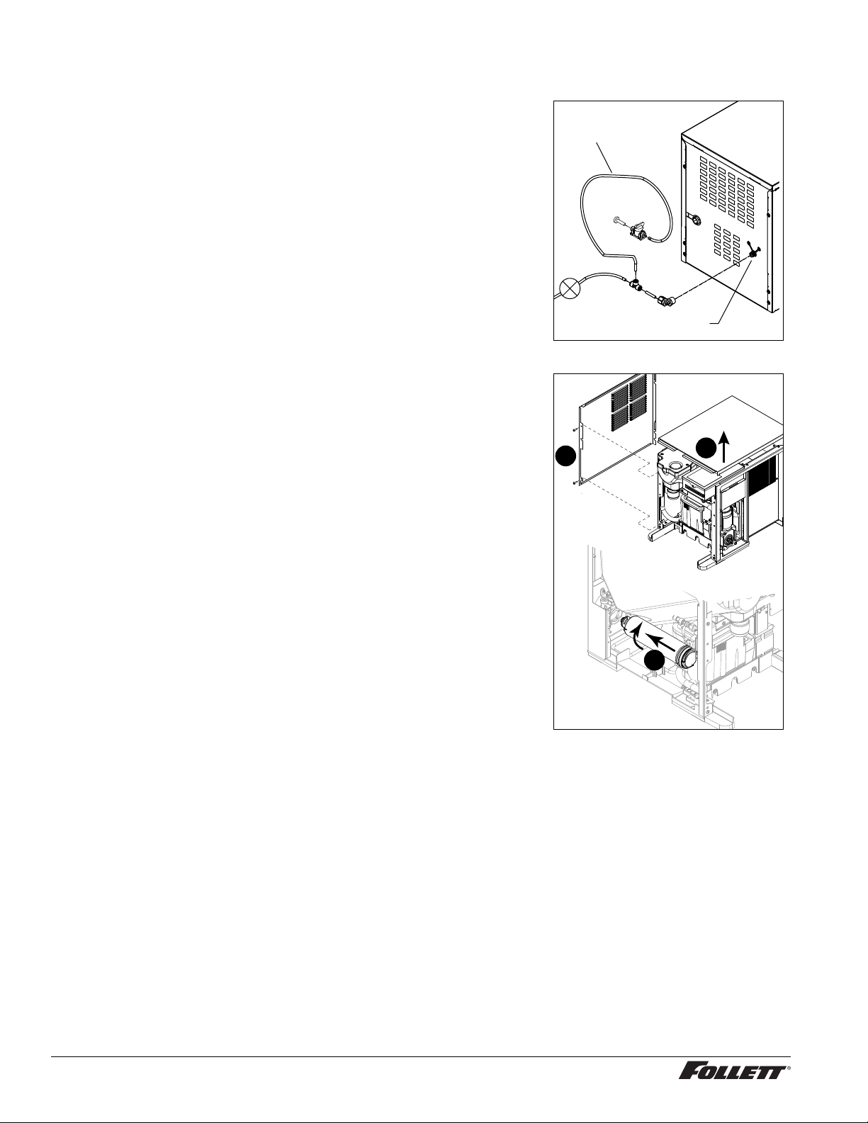
5. Connect water line. Recommended routing (Fig. 3) allows easy access
to water for cleaning and sanitizing procedure.
6. If installing the optional internal water lter*, please complete the
steps shown in
Cleaning and Sanitizing on page 11 before
proceeding. If not, proceed to step 10.
* If your dispenser has the internal water lter option, the water lter must be
installed for the dispenser to operate. Because internal components will need to
be accessed for both procedures, Follett recommends installing the water lter
just prior to initial sanitizing.
7. Lift and remove the top panel, set aside (Fig. 4.1).
8. Remove two screws (Fig. 4.2) and remove left side panel.
9. Install lter as shown. Turn lter clockwise until it is fully seated
(Fig.4.3).
10. Connect power supply.
11. Sanitize the dispenser prior to use (see Cleaning and Sanitizing
on page 11).
Fig. 3
3' (91.4 cm)
Plug
Fig. 4
2
Val ve
1/4" MPT
1
8 Undercounter Dispenser and Ice machine 7UC100A/7UD100A
3
Page 9
Maintenance/Cleaning Mode –––––––––––––––––––––––––––––––––––––––––
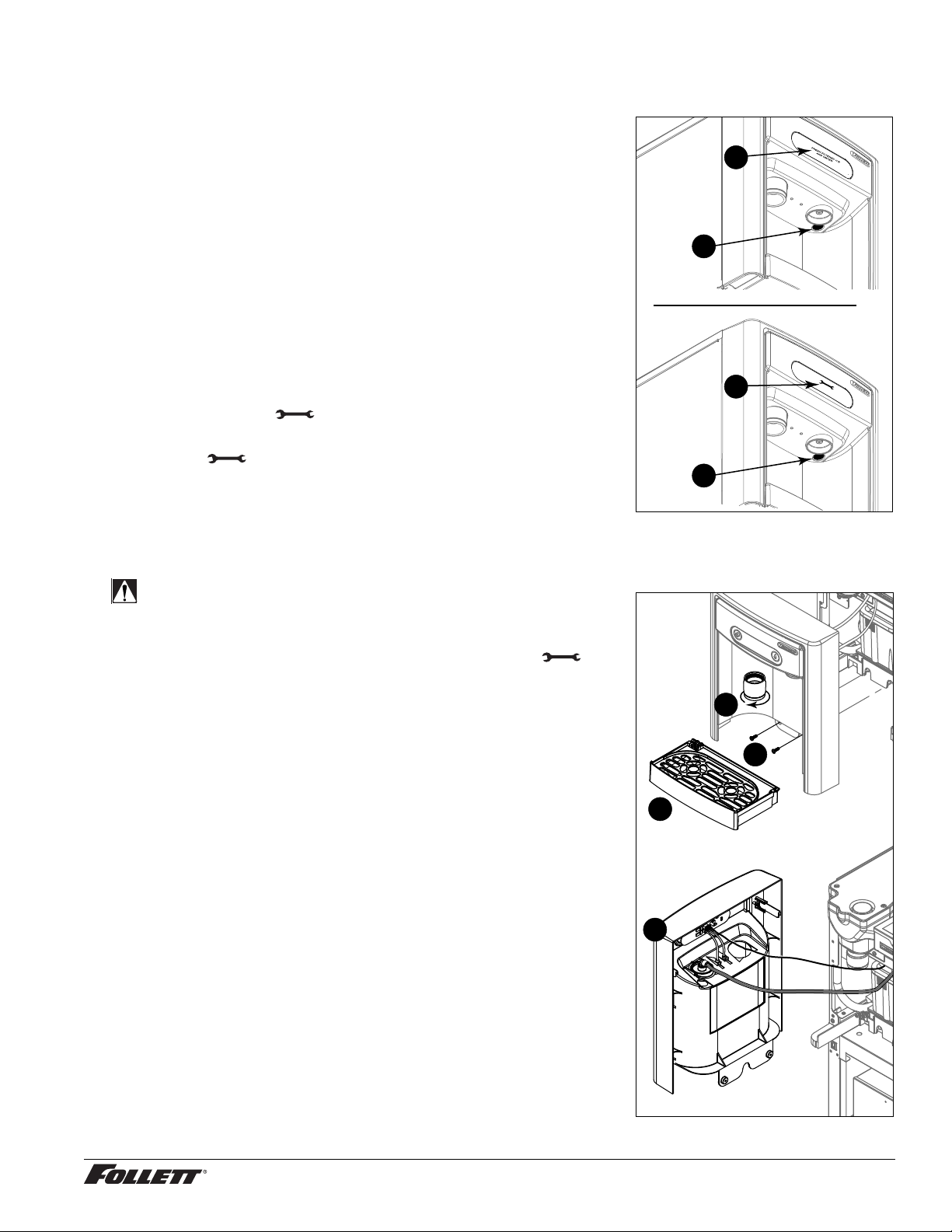
Cleaning Mode (Dispensing Disabled) - Use when cleaning surface
Entering Cleaning Mode disables the User Interface and allows you to clean
the outside of the dispenser without accidentally dispensing water or ice.
1. To enter Cleaning Mode, press and immediately release the
maintenance/clean switch (Fig. 5.1) so that only "FRESH
FILTERED ICE AND WATER" displays in the user interface
(Fig.5.2).
2. To exit Cleaning Mode, press and immediately release the
maintenance/clean switch so that the ice and water icons also
display in the user interface.
Fig. 5
2
1
Maintenance Mode (All Operation Disabled) - Use when cleaning ice
machine
Entering Maintenance Mode disables all operations and allows you to safely
clean and/or sanitize the ice machine and dispenser.
1. To enter Maintenance Mode, press and hold the maintenance/clean
switch (Fig. 5.3) until displays in the user interface (Fig.5.4).
2. To exit Maintenance Mode, press and hold the maintenance/clean
switch until no longer displays in the user interface.
Note: Entering and exiting Maintenance Mode will reset the six-month
periodic maintenance reminder.
4
3
Accessing Internal Components ––––––––––––––––––––––––––––––––––––––
Fig. 6
CAUTION!
Except for routine cleaning and sanitizing, only quali ed
technicians should attempt to service or maintain this equipment.
1. Press and hold the maintenance/clean switch (Fig. 5.1) until
displays in the user interface (Fig. 5.2).
2. Remove (unscrew) chrome ice dispenser chute (Fig. 6.1).
3. Remove the drip tray (Fig. 6.2).
4. Remove the two screws (Fig. 6.3) on the front panel (behind the
drip tray).
5. Remove and set aside the front panel (Fig. 6.4) - do not
disengage the plug on the back of the User Interface or the
tubing at the water dispenser chute (if so equipped).
2
1
3
4
Undercounter Dispenser and Ice machine 7UC100A/7UD100A 9
Page 10
Filter Display Indicator Activation –––––––––––––––––––––––––––––––––––––
If you purchased your dispenser with a Follett lter, the lter display indicator
activation has been preset at the factory.
If you are using an “after market lter,” an adjustment may be made to
activate the “Fresh Filtered Ice & Water” display.
Activating “Fresh Filtered Ice & Water”
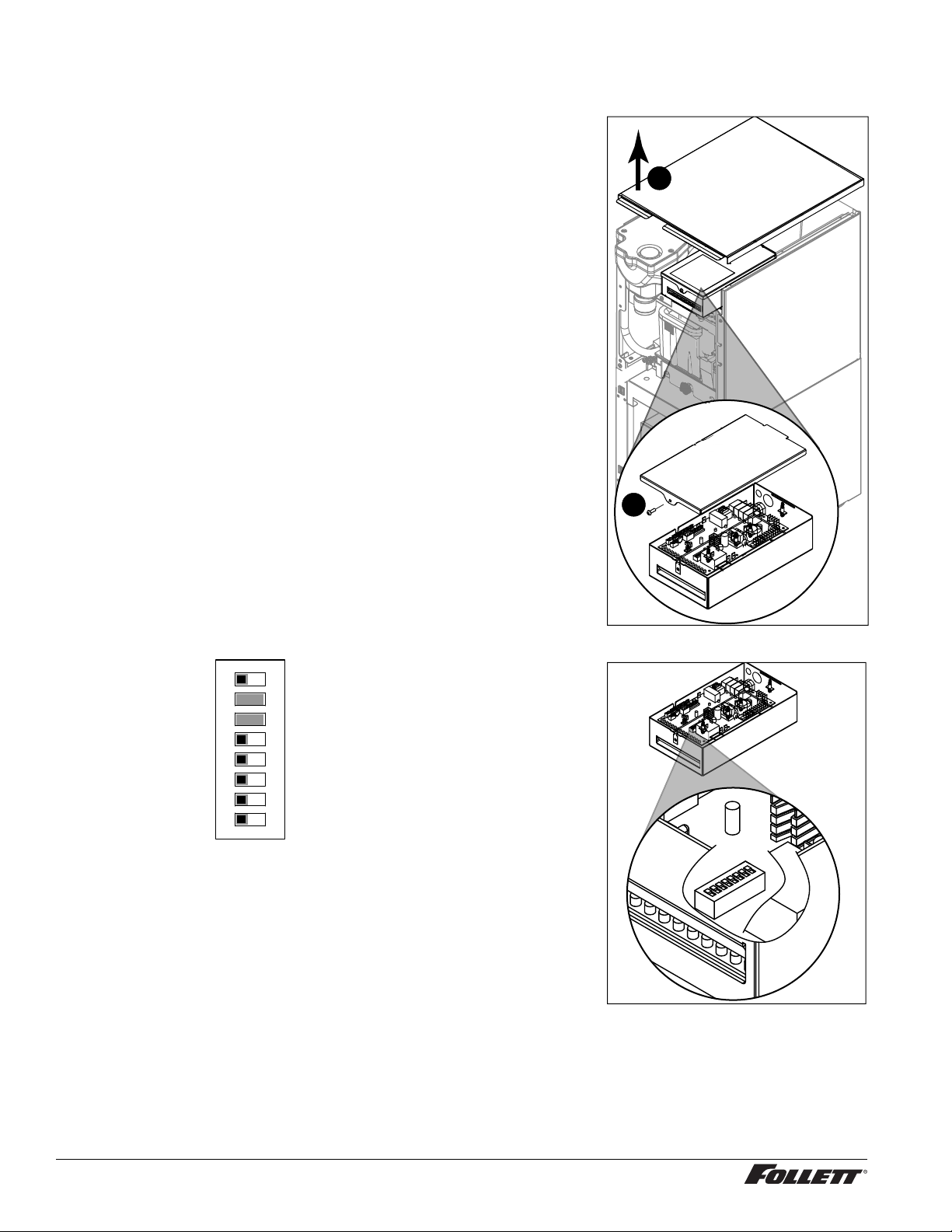
1. Remove the front panel as explained in Accessing Internal
Components on page 9 then refer to Fig. 7.
2. Remove top panel (Fig. 7.1).
3. Remove (1) screw and top of control board enclosure (Fig. 7.2).
4. Locate the DIP switches on the dispenser's control board (Fig. 8).
Use a ne-pointed object to move the “Filter” DIP switch (DIP switch
#3) to the ON position.
Deactivating the Six-Month Maintenance/Filter Change Reminder
1. Use a ne-pointed object to move the “PM” DIP switch (DIP switch
#8) to the ON position.
Fig. 7
1
2
Not used (OFF position)
Ice only
No internal filter
Not used (OFF position)
Not used (OFF position)
15 minute delay
Not used (OFF position)
Six-month PM enabled
OFF ON
Fig. 8
12345678
Ice & water
Internal filter supplied or to display "Fresh Filtered"
30 minute delay
Six-month PM disabled
10 Undercounter Dispenser and Ice machine 7UC100A/7UD100A
Page 11
Cleaning and Sanitizing –––––––––––––––––––––––––––––––––––––––––––––
Cleaning and sanitizing should be performed at least every 6 months (more often if
Fig. 9
local water conditions dictate). For initial startup, only sanitizing is required.
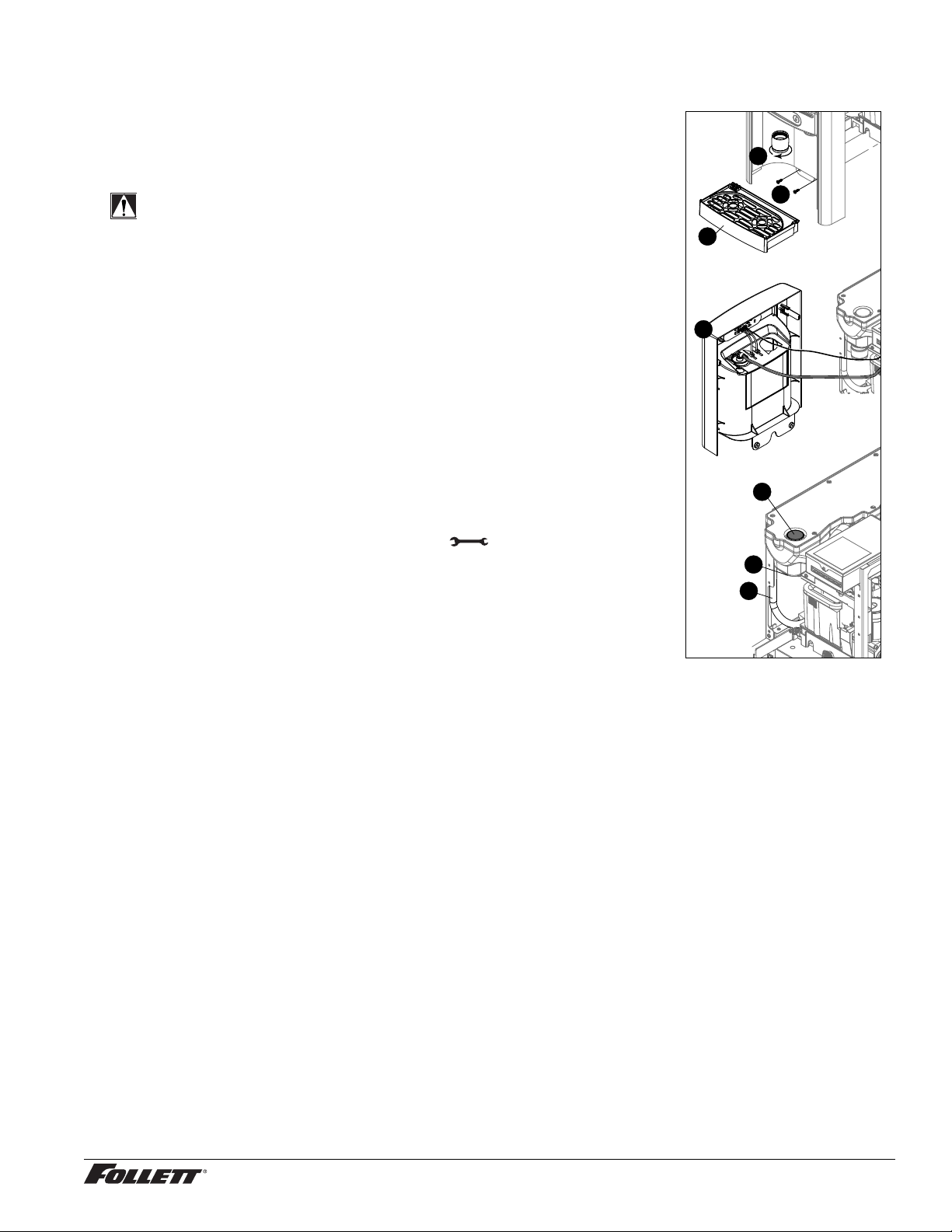
IMPORTANT! Prior to cleaning and sanitizing, the dispenser must be moved
forward at least 4" (10.16 cm). Do not remove the Bin Lid, cleaning and sanitizing
1
solution is added through the Bin Lid Access Spout (Fig. 9.6).
3
WARNING!
§ Place the dispenser in Maintenance Mode prior to servicing or
cleaning the ice machine. See Maintenance/Cleaning Mode on page
2
9.
§ For protection, rubber gloves and safety goggles (and/or face shield)
should be worn when handling Cleaner or Sanitizer.
§ Do not mix Cleaner and Sanitizer together. It is a violation of federal
4
law to use these solutions in a manner inconsistent with their labeling.
§ Do not use bleach, it will damage the dispenser.
Required Supplies
§ (3) x 7 oz. SafeCLEAN™ environmentally-friendly ice machine cleaner
packets
§ Nu-Calgon IMS-II sanitizing concentrate
§ Funnel and Bucket
Cleaning: Ice machine and Dispenser
6
1. Dispense all the ice out of the unit.
2. Press and hold maintenance/clean switch until displays in the user
interface to enter Maintenance Mode.
3. Remove (unscrew) chrome ice dispense chute (Fig. 9.1).
4. Remove drip tray (Fig. 9.2).
7
5
5. Remove (2) screws located behind the drip tray (Fig. 9.3).
6. Move front panel and place on top or beside unit (Fig. 9.4).
7. Remove plug cap from the end of drain tube (Fig. 9.5) 9 lower tube to
drain water into bucket.
8. After the system has been drained of water replace plug cap in drain tube. Secure tube in holder.
9. Remove cap from bin lid cover (Fig. 9.6).
10. Screw bin lid cover cap onto ice discharge chute (Fig. 9.7).
11. Mix SafeCLEAN Ice Machine Cleaner, (3) x 7 oz. packets, with 3gal. (11.4 L) of water.
12. Pour cleaning solution into bin lid access spout until solution reaches the spout neck.
13. Allow the solution to remain in unit for 15 minutes.
14. While machine is cleaning, remove top and right side panel to access and clean air-cooled condenser.
15. Drain system by lowering drain tube into bucket.
16. Secure drain tube into holder.
17. Fill one time with potable water and drain with tube. Secure drain tube.
Sanitizing: Ice machine and Dispenser
1. Complete steps 1-11 above.
2. Mix a sanitizing solution of 2.5 gal. (9.5L) of water and 4 oz. (118 ml) of Nu-Calgon IMS-II sanitizing
concentrate.
3. Pour sanitizing solution into bin lid access spout until solution reaches the spout neck.
4. Allow the solution to remain in unit for 5 minutes.
5. Drain system by lowering drain tube.
6. Secure drain tube into holder.
7. Fill and drain three times with potable water.
8. Place a bucket under the dispense chute and remove cap. Note: Some sanitizing solution will remain and
drain out when cap is removed. Reposition cap on bin lid spout.
9. Reinstall front panel, ice dispense chute, and drip tray.
10. Press and hold maintenance/clean switch to exit Maintenance Mode.
Undercounter Dispenser and Ice machine 7UC100A/7UD100A 11
Page 12
Cleaning and Sanitizing (continued) ––––––––––––––––––––––––––––––––––––––
Cleaning: User Interface and Exterior Cabinet
1. Press and release maintenance/clean switch so that only "FRESH FILTERED ICE AND WATER" displays
in the user interface to enter Cleaning Mode (and disable dispensing).
2. Plastic parts, including the user interface, can be cleaned with a non-abrasive glass cleaner. Clean
stainless steel panels with stainless steel cleaner.
3. Press and release maintenance/clean switch to put unit back into service.
Service –––––––––––––––––––––––––––––––––––––––––––––––––––––––––––
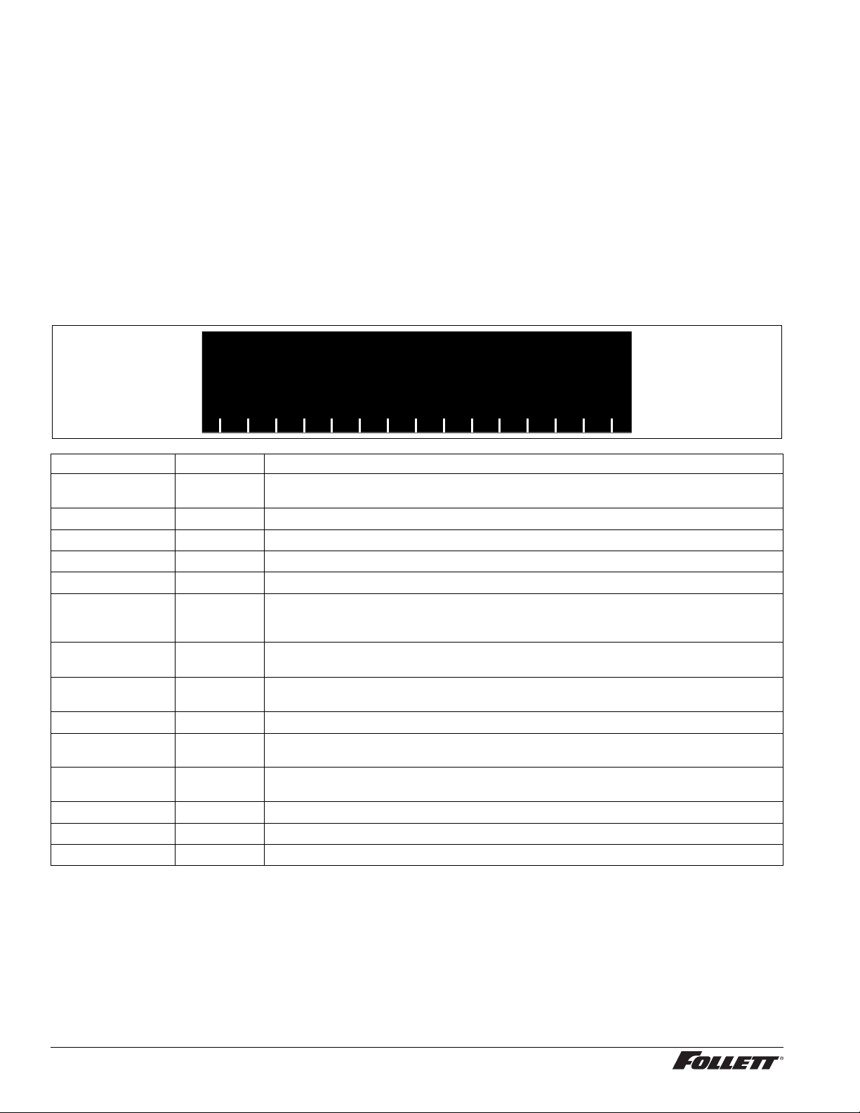
LED Indicator Description
The LED Indicator is located behind the front panel.
Fig. 10
Clean
LED Name LED Color Description
Clean Green The dispenser is in Cleaning Mode. Dispenser is disabled to allow for cleaning of front
— N/A Not used.
PM Red Six-month periodic maintenance required.
Drip tray Red Drip tray full.
Water leak Red Internal leak in dispenser.
High amps Red Auger gearmotor has exceeded 0.55A. The HI amps and Time delay LEDs will illuminate,
Service Red 8000 hour bushing check (call Follett technical service group at (877) 612-5086 or
Maintenance Yellow Enter Maintenance Mode by pressing and holding maintenance/clean switch for 5 seconds.
Low water Yellow Insufficient water supply to machine or no low bin LED upon startup.
Time delay Yellow Ice production will not resume for at least 15 minutes after a full bin is achieved and a
Sleep cycle Green After a full bin and 10 minutes of non-use, the unit goes into standby and will not produce
Making ice Green Gearmotor, compressor, and fan motor energized.
Low bin Green Bin switch closed calling for ice.
Power on Green Power supplied to unit.
PM
Drip tray
Water leak
HI press
HI amps
Service
Maint
Low water
Time delay
Sleep cycle
Making ice
Low bin
Power ON
panel. See Maintenance/Cleaning Mode on page 9.
the machine will shut down for one hour, the LEDs will turn off, and the machine will
resume normal operation.
+1 (610) 252-7301).
Unit will not make or dispense ice.
minimum amount of dispense activity has elapsed.
ice until either 12 hours has elapsed or ice or water has dispensed.
12 Undercounter Dispenser and Ice machine 7UC100A/7UD100A
Page 13
Service (continued) ––––––––––––––––––––––––––––––––––––––––––––––––––––
Evaporator Disassembly
1. Disconnect power from the dispenser.
2. Turn off water supply to dispenser.
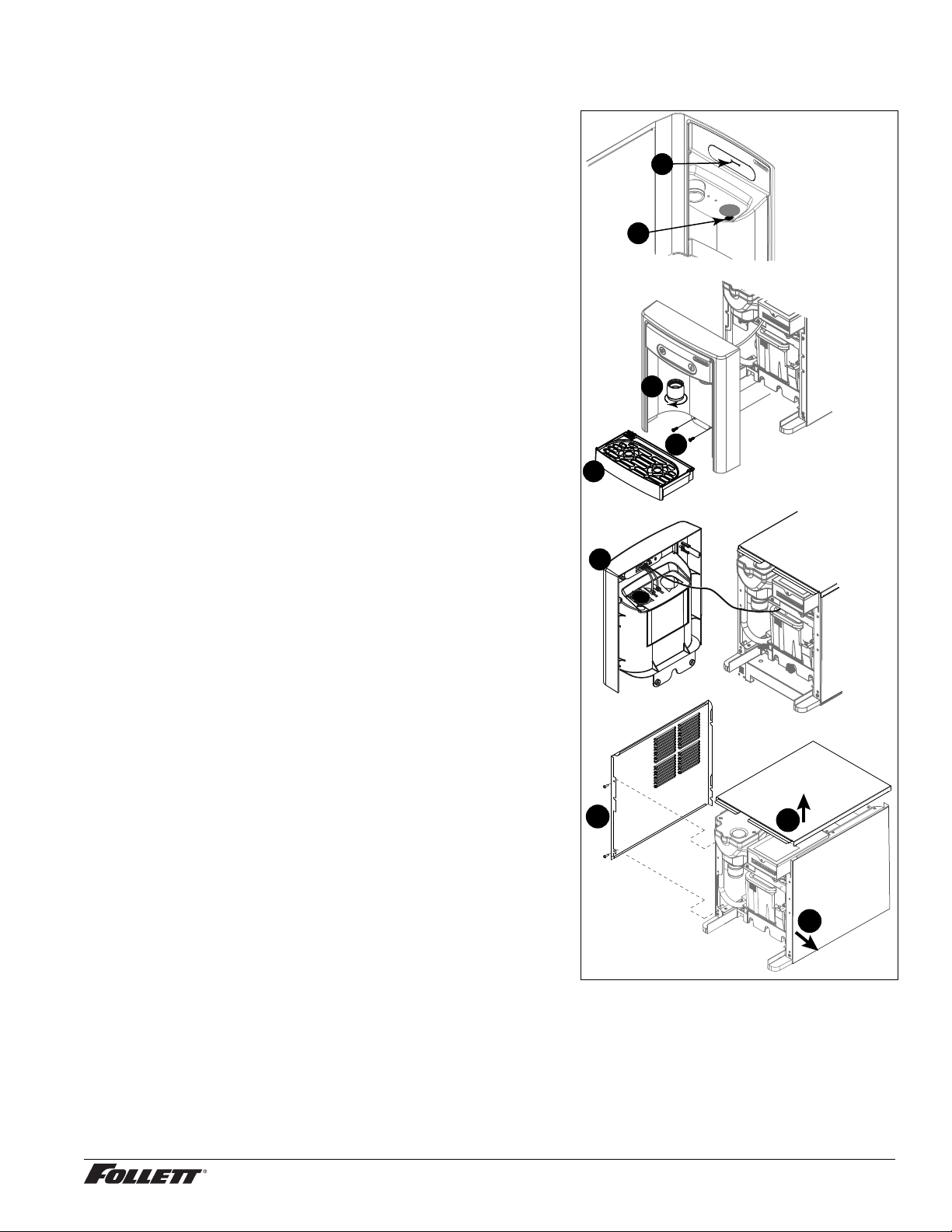
3. Remove (unscrew) chrome ice dispenser chute (Fig.11.1).
4. Remove the drip tray (Fig. 11.2).
5. Remove the two screws (Fig. 11.3) on the front panel
(behind the drip tray).
6. Remove and set aside the front panel (Fig. 11.4) - do not
disengage the plug on the back of the User Interface.
7. Lift and remove the top panel, set aside (Fig.16.5).
8. Remove two screws (Fig. 11.6) and remove left side panel.
9. Remove two screws (Fig. 11.7) and remove right side
panel.
Fig. 11
2
1
1
3
2
4
6
5
7
Undercounter Dispenser and Ice machine 7UC100A/7UD100A 13
Page 14
Service (continued) ––––––––––––––––––––––––––––––––––––––––––––––––––––
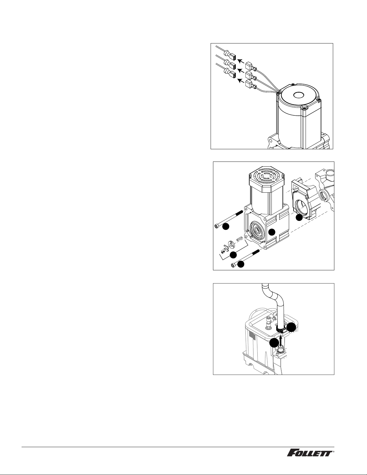
10. Unplug the gear motor (three connectors) (Fig.12).
11. Remove ground screw connection.
12. Remove gear motor:
§ Remove M6 allen screw, retainer, spacer and key (Fig. 13.1).
§ Remove two M6x90 allen screws (Fig. 13.2).
§ Pull gear motor from auger (Fig. 13.3).
§ Remove main housing insulation (Fig. 13.4).
13. Remove all traces of petro-gel from auger shaft.
Fig. 12
Fig. 13
14. Remove compression nozzle:
§ Loosen hose clamp (Fig.14.1).
§ Remove transport tube (Fig. 14.2).
4
2
3
1
2
Fig. 14
1
2
14 Undercounter Dispenser and Ice machine 7UC100A/7UD100A
Page 15
Service (continued) –––––––––––––––––––––––––––––––––––––––––––––––––––
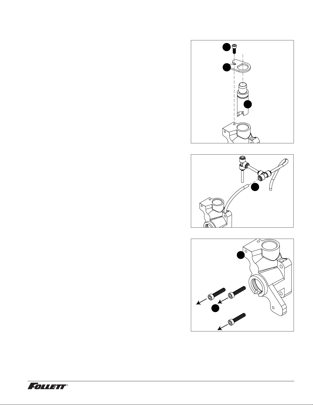
15. Remove M6 socket head allen screw (Fig.15.1).
16. Remove compression nozzle retainer (Fig. 15.2).
17. Remove compression nozzle (Fig. 15.3).
18. Remove main housing:
§ Disconnect vent line from T tting (Fig.16.1).
Fig. 15
1
2
3
Fig. 16
19. Remove three M6x25 socket head allen screws
(Fig.17.1).
20. Remove main housing (Fig. 17.2).
1
Fig. 17
2
1
Undercounter Dispenser and Ice machine 7UC100A/7UD100A 15
Page 16
Service (continued) –––––––––––––––––––––––––––––––––––––––––––––––––––
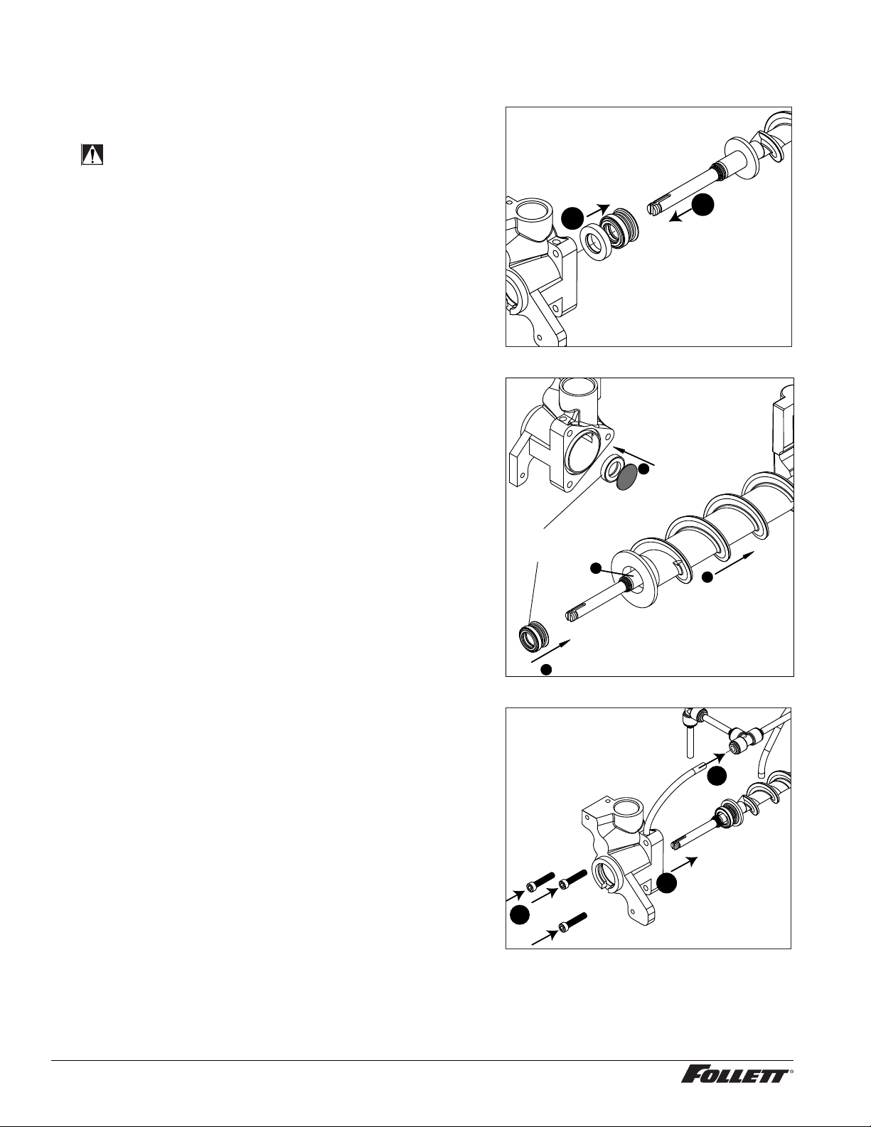
21. Remove and discard mating ring and seal (Fig.18.1).
22. Carefully remove auger (Fig. 18.2).
WARNING!
Use caution when removing auger. The auger is very
sharp - handle with care to avoid personal injury.
Evaporator Assembly
1. Remove and inspect main housing O-ring seal. Replace if
damaged in any way.
2. Clean O-ring groove. Lubricate O-ring with Petro-gel and
reinstall.
3. Use cardboard disc to press new mating ring into main
housing (Fig. 19.1).
4. Lube the shaft with liquid soap in the area shown
(Fig.19.2) and slip on seal and spring (Fig. 19.3).
Note: Do not touch the sealing surfaces with bare hands.
Contact with bare skin will cause premature seal failure.
5. Install auger (Fig. 19.4).
Fig. 18
Fig. 19
Do NOT
touch!
1
Cardboard
disc
2
2
1
4
6. Install main housing:
§ Slide main housing onto auger shaft (Fig.20.1).
§ Install three M6x25 allen screws (Fig.20.1).
§ Connect vent line to T tting (Fig.20.1).
16 Undercounter Dispenser and Ice machine 7UC100A/7UD100A
3
Fig. 20
3
1
2
Page 17
Service (continued) –––––––––––––––––––––––––––––––––––––––––––––––––––
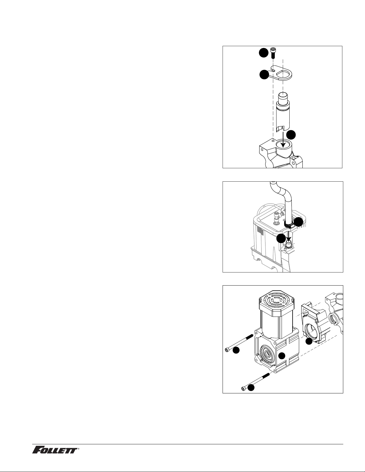
7. Install compression nozzle:
§ Remove and inspect compression nozzle O-ring seal.
Replace if damaged in any way.
§ Clean O-ring groove. Lubricate O-ring with Petro-gel and
reinstall.
§ Install compression nozzle (Fig.21.1).
§ Install compression nozzle retainer (Fig.21.2).
§ Install M6 socket head allen screw (Fig.21.3).
8. Install transport tube (Fig. 22.1).
9. Tighten hose clamp (Fig.22.2).
Fig. 21
3
2
1
Fig. 22
10. Install gear motor:
§ Install main housing insulation (Fig.23.1).
§ Slide gear motor onto auger shaft (Fig.23.2).
§ Install two M6x90 allen screws (Fig. 23.3).
2
1
Fig. 23
1
3
2
3
Undercounter Dispenser and Ice machine 7UC100A/7UD100A 17
Page 18
Service (continued) –––––––––––––––––––––––––––––––––––––––––––––––––––
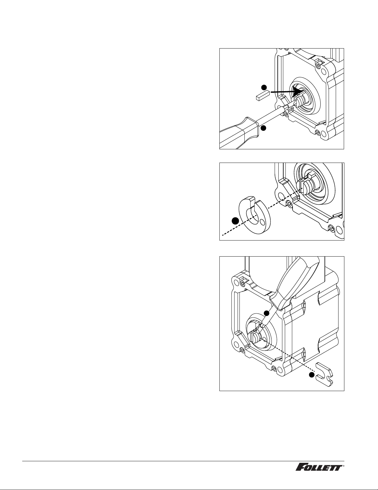
11. Use screwdriver to orient auger shaft to align with motor
shaft keyway (Fig. 24.1).
12. Install key into keyway (Fig. 24.2).
13. Install spacer, ensure that key is captured in slot
(Fig.25.1)
Fig. 24
2
1
Fig. 25
1
14. Insert screwdriver into groove of auger shaft and pry shaft
outwards (Fig.26.1).
15. Insert retainer into groove (Fig.26.2), ensure that retainer
is aligned with hole in spacer.
Fig. 26
1
2
18 Undercounter Dispenser and Ice machine 7UC100A/7UD100A
Page 19
Service (continued) –––––––––––––––––––––––––––––––––––––––––––––––––––
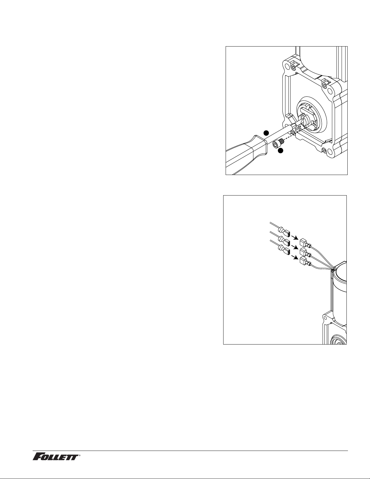
16. Install screw and tighten (Fig.27.1). Fig. 27
1
2
17. Plug in gear motor (Fig.28).
§ BLUE to BLUE
§ BLACK to BLACK
§ WHITE to WHITE
§ Connect ground wire with ground screw.
Fig. 28
BLUE to BLUE
BLACK to BLACK
WHITE to WHITE
Undercounter Dispenser and Ice machine 7UC100A/7UD100A 19
Page 20
Service (continued) ––––––––––––––––––––––––––––––––––––––––––––––––––––
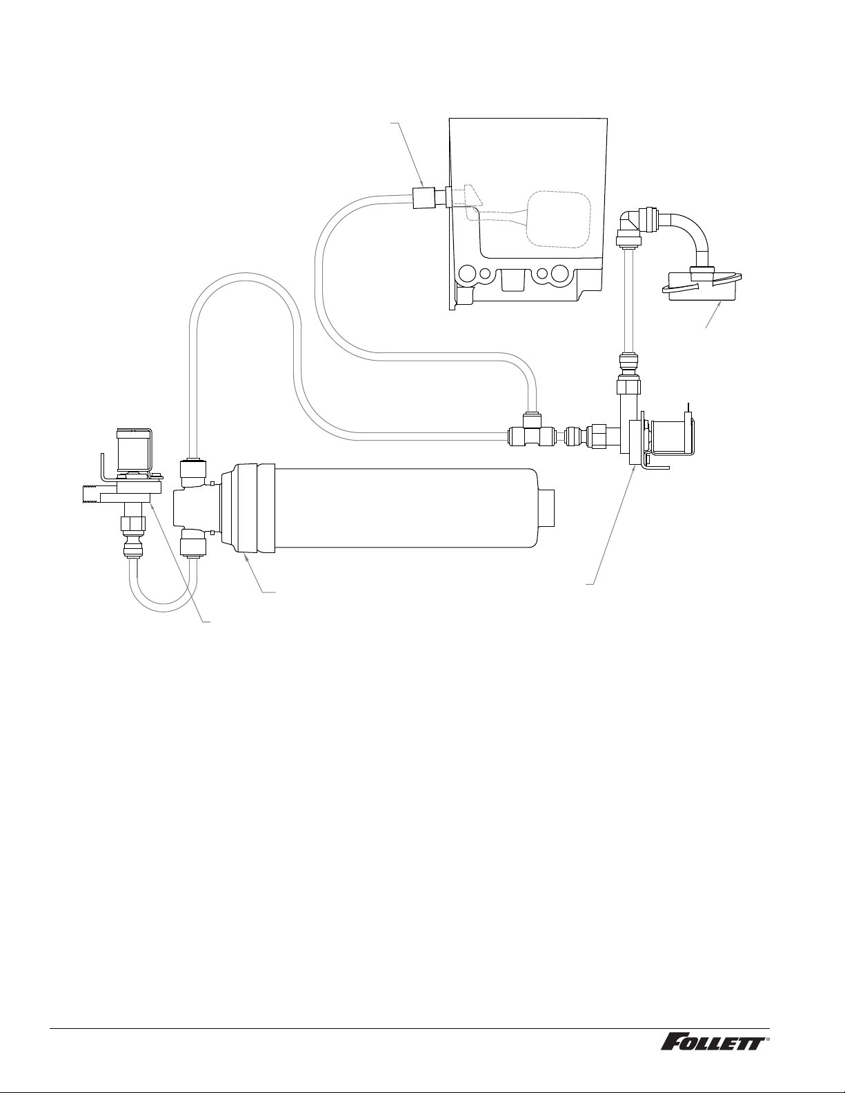
Water Feed Schematic
Evaporator
Float
Water Chute
(optional)
Filter (optional)
Water Solenoid Valve
Water Solenoid Valve
(optional)
20 Undercounter Dispenser and Ice machine 7UC100A/7UD100A
Page 21
Service (continued) ––––––––––––––––––––––––––––––––––––––––––––––––––––
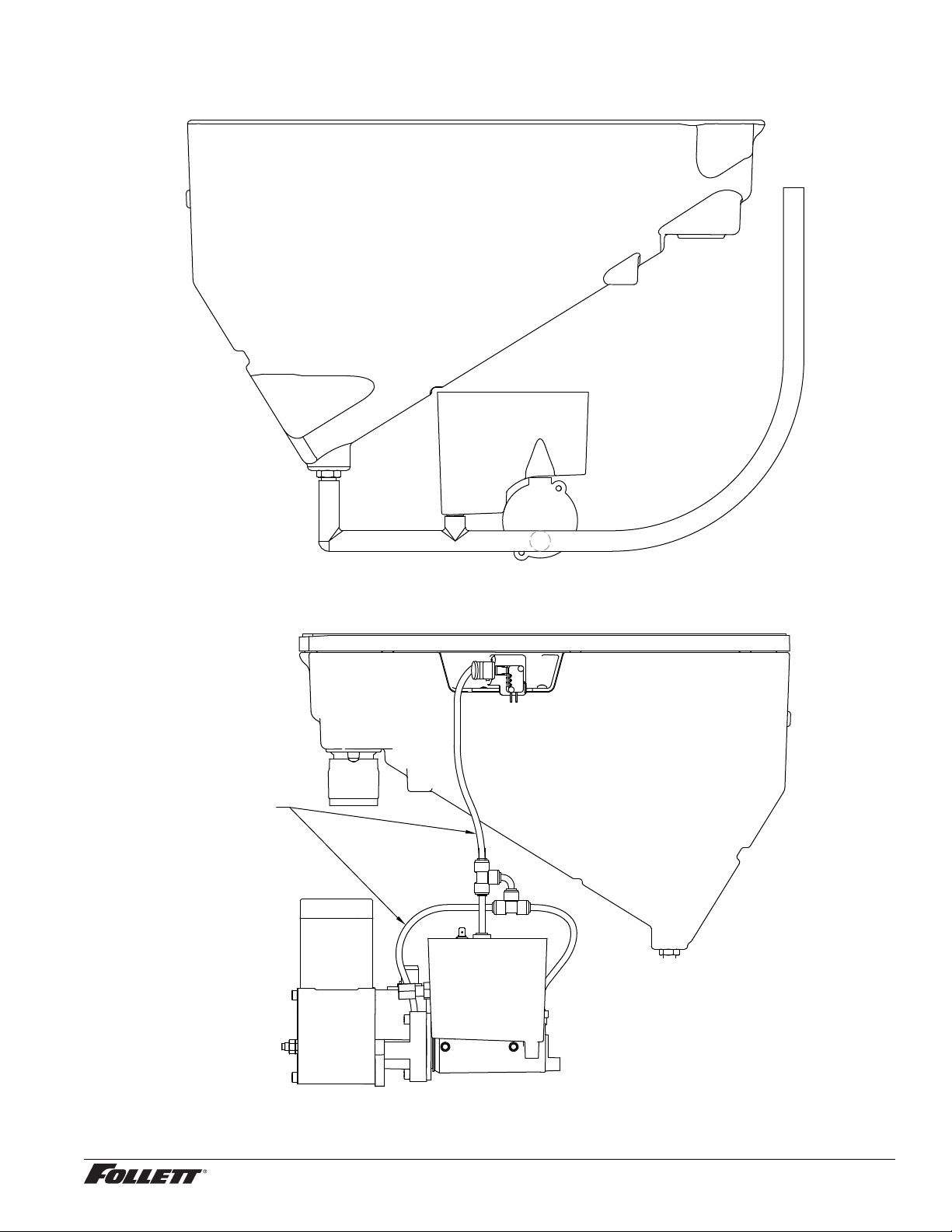
Bin Melt Water/Evaporator Feed/Clean Out System Schematic
Storage Bin
Vent System Schematic
Vent Tube
Storage Bin
Reservoir
Undercounter Dispenser and Ice machine 7UC100A/7UD100A 21
Page 22
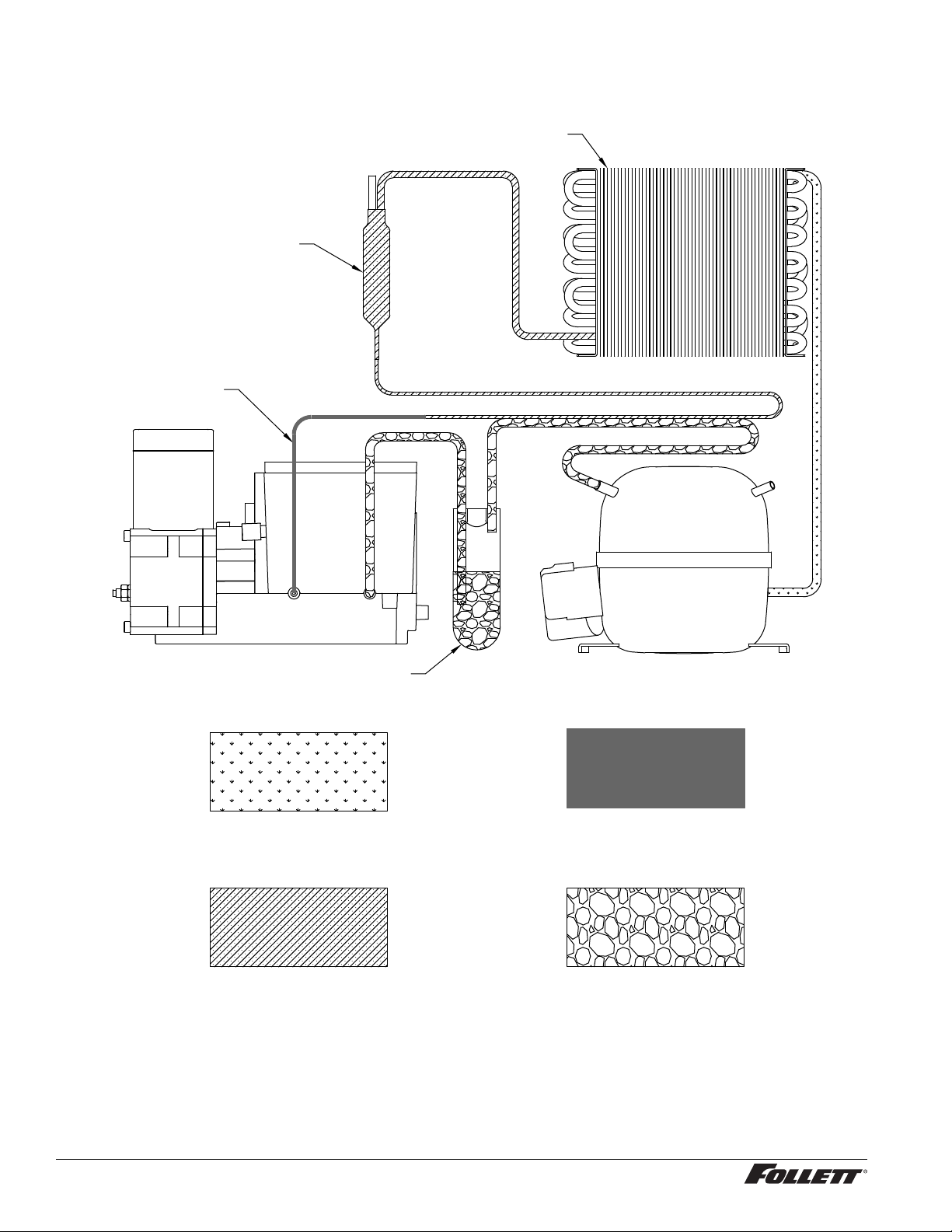
Service (continued) ––––––––––––––––––––––––––––––––––––––––––––––––––––
Refrigeration Schematic
CONDENSER
FILTER-DRIER
CAP TUBE
COMPRESSOR
EVAPORATOR
ACCUMULATOR
HIGH PRESSURE VAPOR
HIGH PRESSURE LIQUID LOW PRESSURE VAPOR
LOW PRESSURE LIQUID
22 Undercounter Dispenser and Ice machine 7UC100A/7UD100A
Page 23
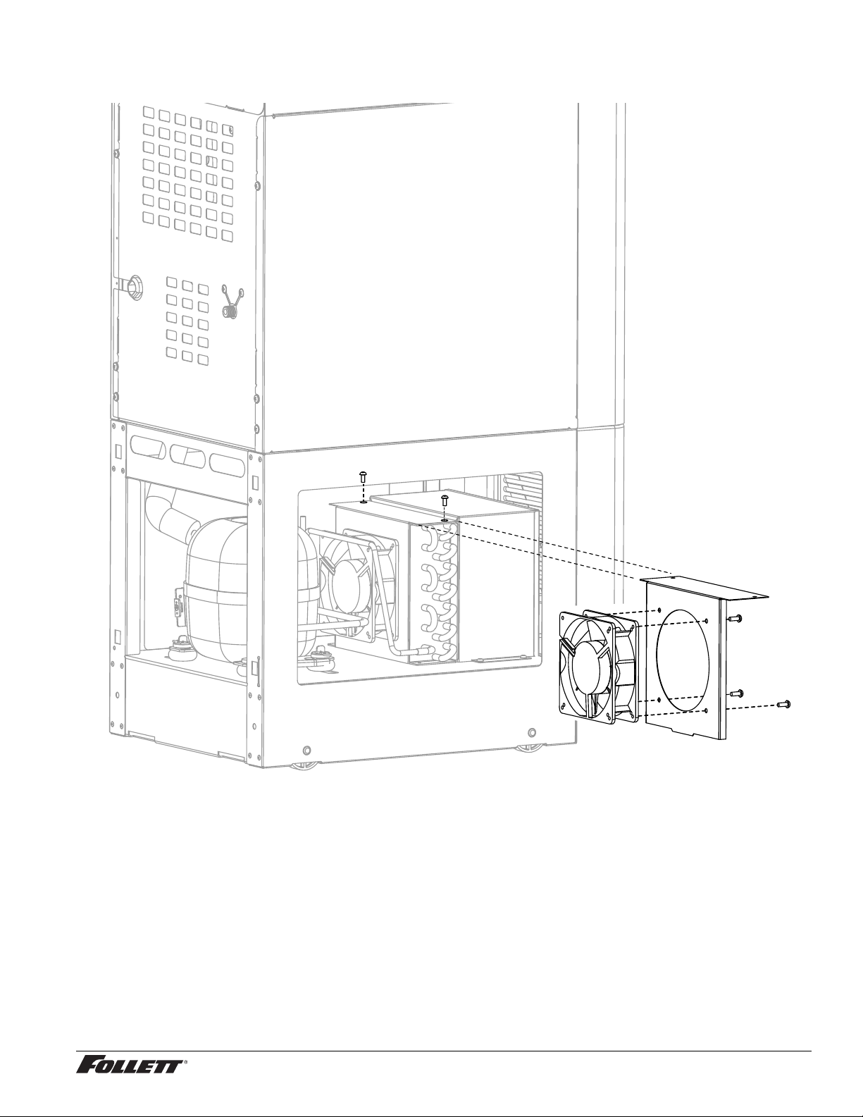
Service (continued) ––––––––––––––––––––––––––––––––––––––––––––––––––––
Condenser Fan Motor Removal
Undercounter Dispenser and Ice machine 7UC100A/7UD100A 23
Page 24
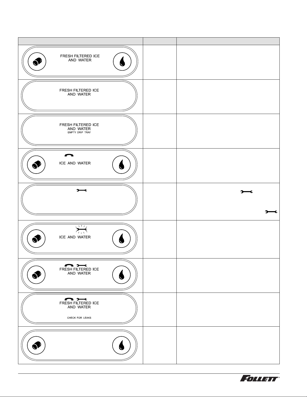
Service (continued) ––––––––––––––––––––––––––––––––––––––––––––––––––––
User Interface Display Identi cation
Operation Display
PM
Condition
Normal
operation
Cleaning
Mode
Drip tray full Empty drip tray.
Six-month
periodic
maintenance
required
Press and release maintenance/clean switch to
clean the user interface without dispensing ice
or water (see
page 9
).
Follow Maintenance Mode procedure (below)
and also see
11
.
Cleaning and Sanitizing on page
Procedure
—
Maintenance/Cleaning Mode on
Maintenance
Mode
Service - 8000
hr bushing
check
High amps Contact Follett technical service group at (877)
Internal leak in
dispenser
Sleep mode Press either dispense button to return to normal
Enter Maintenance Mode by pressing
maintenance/clean switch until
Complete the cleaning and sanitizing procedure
shown on
equipped. Exit Maintenance Mode by pressing
and holding maintenance/clean switch until
no longer displays.
Call Follett Technical Service Group at (877)
612-5086 or +1 (610) 252-7301. The ashing
wrench indicates that the 8000 hr bushing check
is required.
612-5086 or +1 (610) 252-7301.
Note: For dispensers after serial number
Locate leak and repair - Press reset on control
board. Contact Follett if ice machine is leaking.
operation.
page 11 and change the lter, if so
D45191, the phone and wrench will not be
illuminated.
displays.
24 Undercounter Dispenser and Ice machine 7UC100A/7UD100A
Page 25
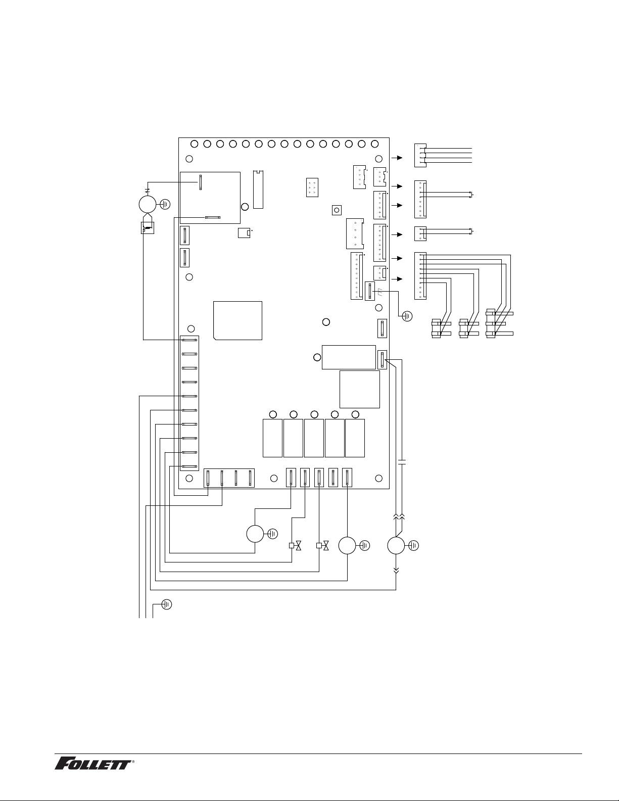
Service (continued) ––––––––––––––––––––––––––––––––––––––––––––––––––––
Electrical Wiring Diagram
POWER
LOW BIN
MAKING ICE
SLEEP CYCLE
TIME DELAY
LOW WATER
MAINTENANCE
SERVICE
HI AMPS
HI PRESSURE
WATER LEAK
DRIP TRAY
PM
CLEAN
D1
D2
D3
COMPRESSOR
BLACK
#1
O.L.
C
S
#2 WHITE
GRN-YEL
#3
COMP.
R
START
RELAY
P16
P15
ICE AUX WATER AUX
T1
#20 BLACK
D6
D5
D4
S1
K1
D16
HI PRS
P14
D9
D8
D7
MODEL SELECT
D11
D12
D10
5
6
PROGRAM
1
P9
2
RESET
S2
P10
D37
UV ON
D18
K3
D13
D14
RS485 UI
P7
SERIAL COMM
P17
WATER LEVELS
P18
D15
P8
SPARE CTS
P13
P11
BIN CLEAN SAFE RS485
P12
UV LIGHT
P5
P4
AUGER
P17
WATER LEVELS
#19
RS485 UI
P7
BINP12 CLEAN SAFEP11
GRN-YEL
USER
INTERFACE
CLEAN
MAINT.
BIN
YELLOW
ORANGE
BLACK
N
L1
POWER
GND
P2
N NNNNN NN N
D19
D22
K7K6
K4K2
#14
ICE DISP
GRN-YEL
#16
P6
WHITE
L1 L1L1
P1
BLACK
#12
DISP.
WHITE
#13
P21
#15 BLACK
FAILSAFE SOLENOID VALVE
D21
FSWD
P20
T2
CURRENT SENS
D20
K5
CO2
P19
P3
#17 BLACK
WATER DISPENSE VALVE
#18 WHITE
WATER SENSOR
CHASSIS
DRIP TRAY WATER
D17
BLUE
#5
AUGER
CAP
FAN
BLUE
BLACK
#7
#8
BLACK
GRN-YEL
#4
FAN
BLACK
BLUE/
WHITE/
#10
PINK
GRAY
WHITE
AUGER
BLACK
GRN-YEL
#11
SENSOR
WATER SENSOR
RESERVOIR
Undercounter Dispenser and Ice machine 7UC100A/7UD100A 25
Page 26
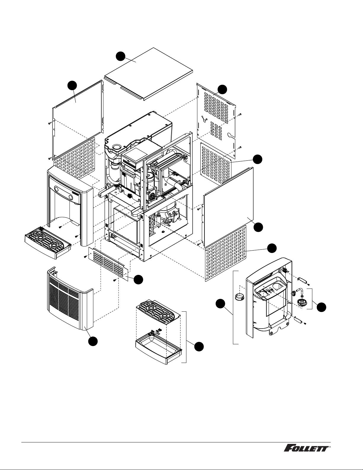
Parts –––––––––––––––––––––––––––––––––––––––––––––––––––––––––––––
Exterior
6
4
7
11
5
10
9
8
1
26 Undercounter Dispenser and Ice machine 7UC100A/7UD100A
2
3
Page 27
Parts (continued) ––––––––––––––––––––––––––––––––––––––––––––––––––––––
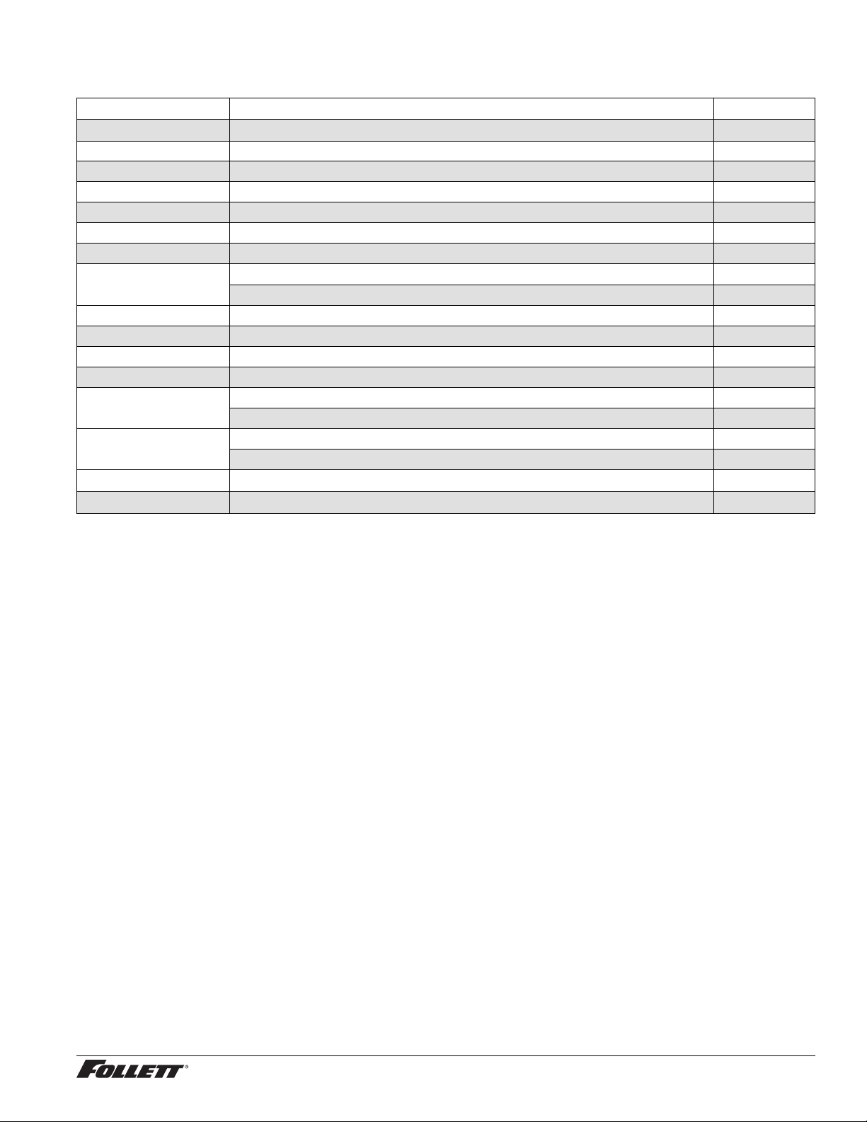
Exterior
Reference # Description Part #
1 Drain, Tray Assy 00957613
2 Panel, Front Assy - Includes Water Nozzle and Plug 00957621
3 Chute, Water (water option) 00957688
4 Panel, Top Left 00924761
5 Panel, Top Right 00924779
6 Panel, Top 00957654
7 Panel, Rear 00957662
8
9 Panel, Intake 00924787
Not Shown Cord, 115 VAC 00958058
Not Shown Packaging for Returns, Dispenser 00957993
Not Shown Covers, Agion, User Interface 00969030
10
11
Not Shown Fitting, Elbow - 1/4" FPT x 1/4" Tube 00974261
Not Shown Drip Tray Drain Kit 00956375
Panel, Lower, 7UC100A Height: 12.0" (304.8 mm) 00924738
Panel, Lower, 7UD100A Height: 10.0" (254 mm) 00924746
Panel, Bottom Left/Right, 7UC100A 00967331
Panel, Bottom Left/Right, 7UD100A 00967356
Panel, Bottom Rear, 7UC100A 00967349
Panel, Bottom Rear, 7UC100A 00967364
Undercounter Dispenser and Ice machine 7UC100A/7UD100A 27
Page 28
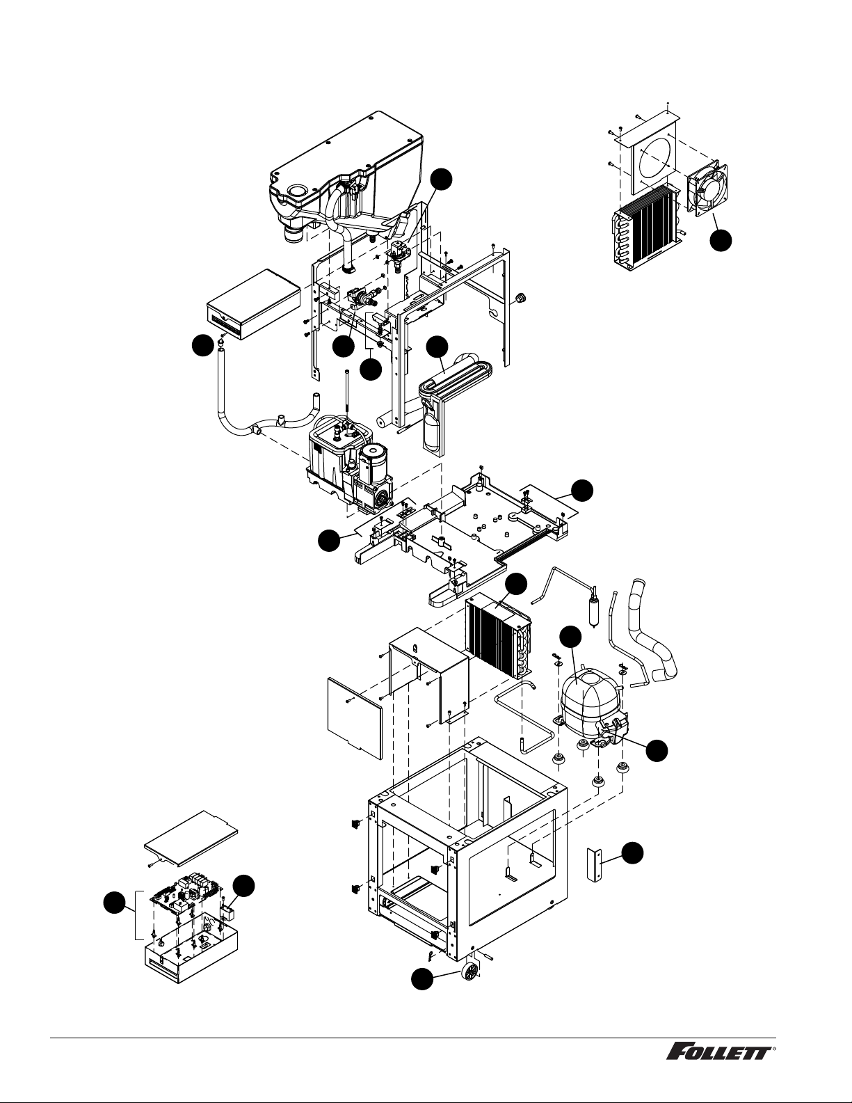
Parts (continued) ––––––––––––––––––––––––––––––––––––––––––––––––––––––
Interior
4
7
3
10
1
2
12
10
6
5
9
8
13
28 Undercounter Dispenser and Ice machine 7UC100A/7UD100A
11
14
Page 29
Parts (continued) ––––––––––––––––––––––––––––––––––––––––––––––––––––––
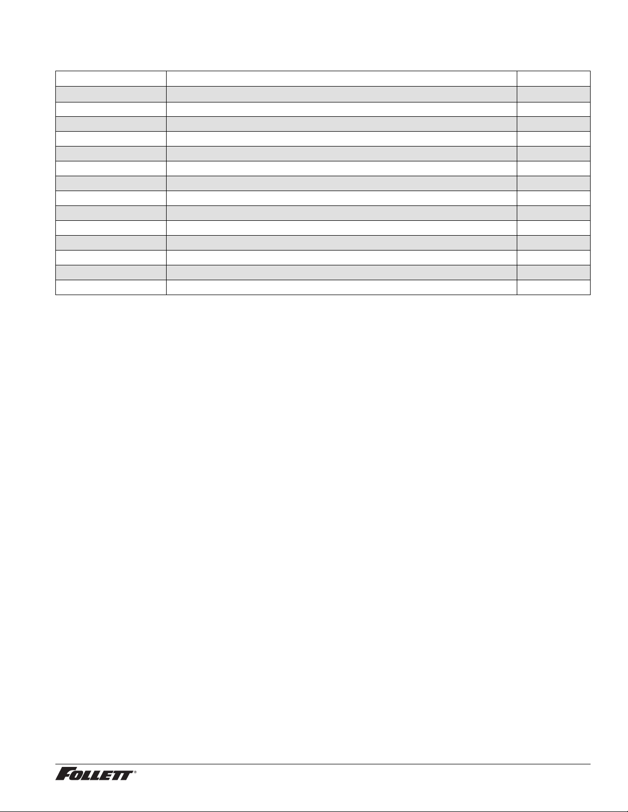
Interior
Reference # Description Part #
1 Valve, Dispense Solenoid (water option) 00957704
2 Switch, Cleaning 00957712
3 Drain/Feed Tube with Cap 00957720
4 Valve, Failsafe Solenoid 00957738
5 Compressor with Mounting Hardware 00958009
6 Condenser 00958017
7 Condenser Fan and Cord 00958025
8 Control Board with Stand-offs 00958033
9 Capacitor, Gearmotor 00958041
10 Sensor, Retainer Hardware Kit 00958066
11 Relay and Overload 00958090
12 Refrigeration, Piping Assy 00958132
13 Roller Kit, Set of 4 00924753
14 Bracket, Stop 00924795
Undercounter Dispenser and Ice machine 7UC100A/7UD100A 29
Page 30
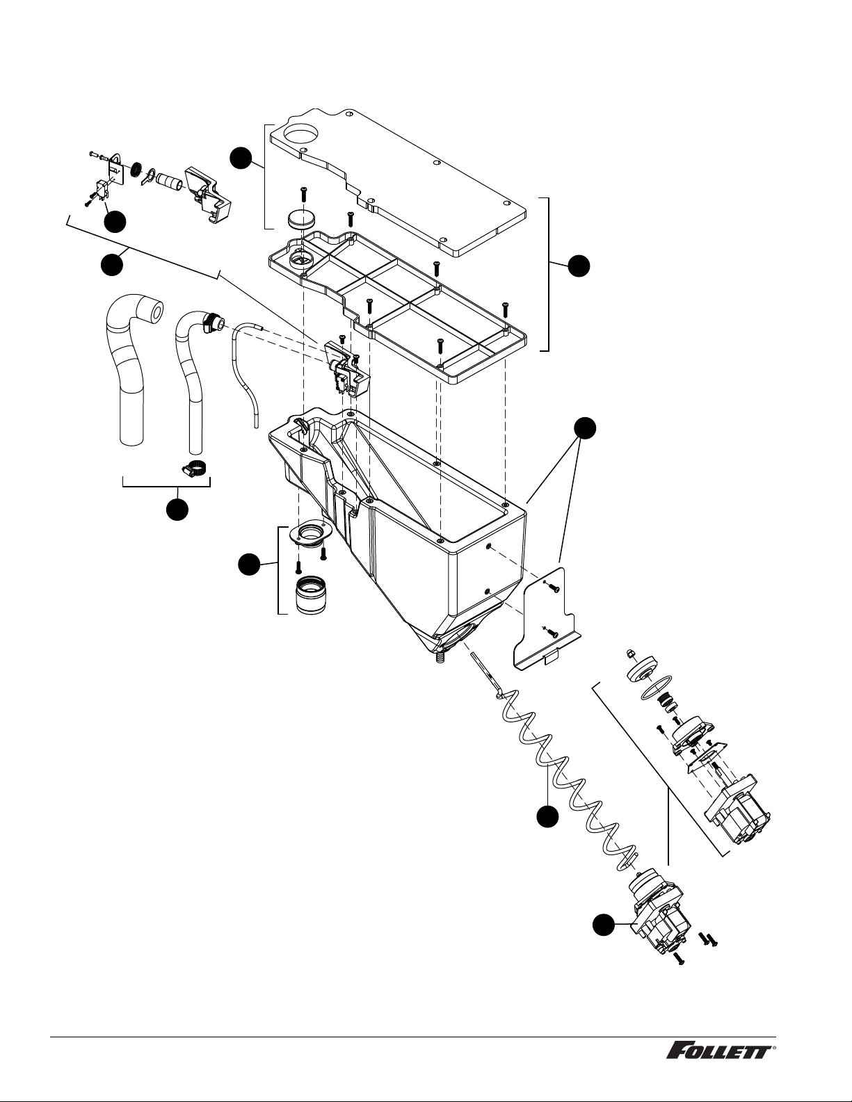
Parts (continued) ––––––––––––––––––––––––––––––––––––––––––––––––––––––
Bin Assembly
9
3
4
2
1
5
6
30 Undercounter Dispenser and Ice machine 7UC100A/7UD100A
7
8
Page 31
Parts (continued) ––––––––––––––––––––––––––––––––––––––––––––––––––––––
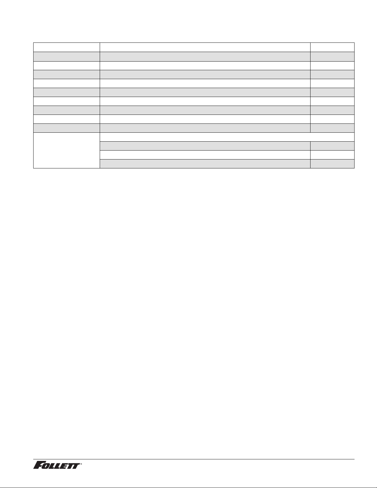
Bin Assembly
Reference # Description Part #
1 Ice Chute Assembly 00957670
2 Ice Transport Tubing with Insulation 00957746
3 Switch, Shuttle 00957753
4 Shuttle, Complete Assy 00957761
5 Lid, Bin Assy 00957779
6 Bin, Assy 00957787
7 Auger, Dispense 00957795
8 Motor, Dispense 00957803
9 Cap and Insulation, Bin 00957936
Not Shown For serial numbers D17619 and below:
Bin Cap 00931519
Ice Chute 00927210
Chute Adapter 00926550
Undercounter Dispenser and Ice machine 7UC100A/7UD100A 31
Page 32
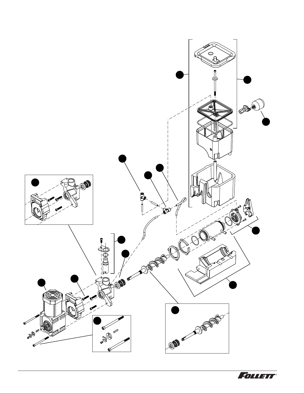
Parts (continued) ––––––––––––––––––––––––––––––––––––––––––––––––––––––
Evaporator Assembly
10
11
12
13
14
13
2
8
5
6
1
3
7
4
9
32 Undercounter Dispenser and Ice machine 7UC100A/7UD100A
Page 33
Parts (continued) ––––––––––––––––––––––––––––––––––––––––––––––––––––––
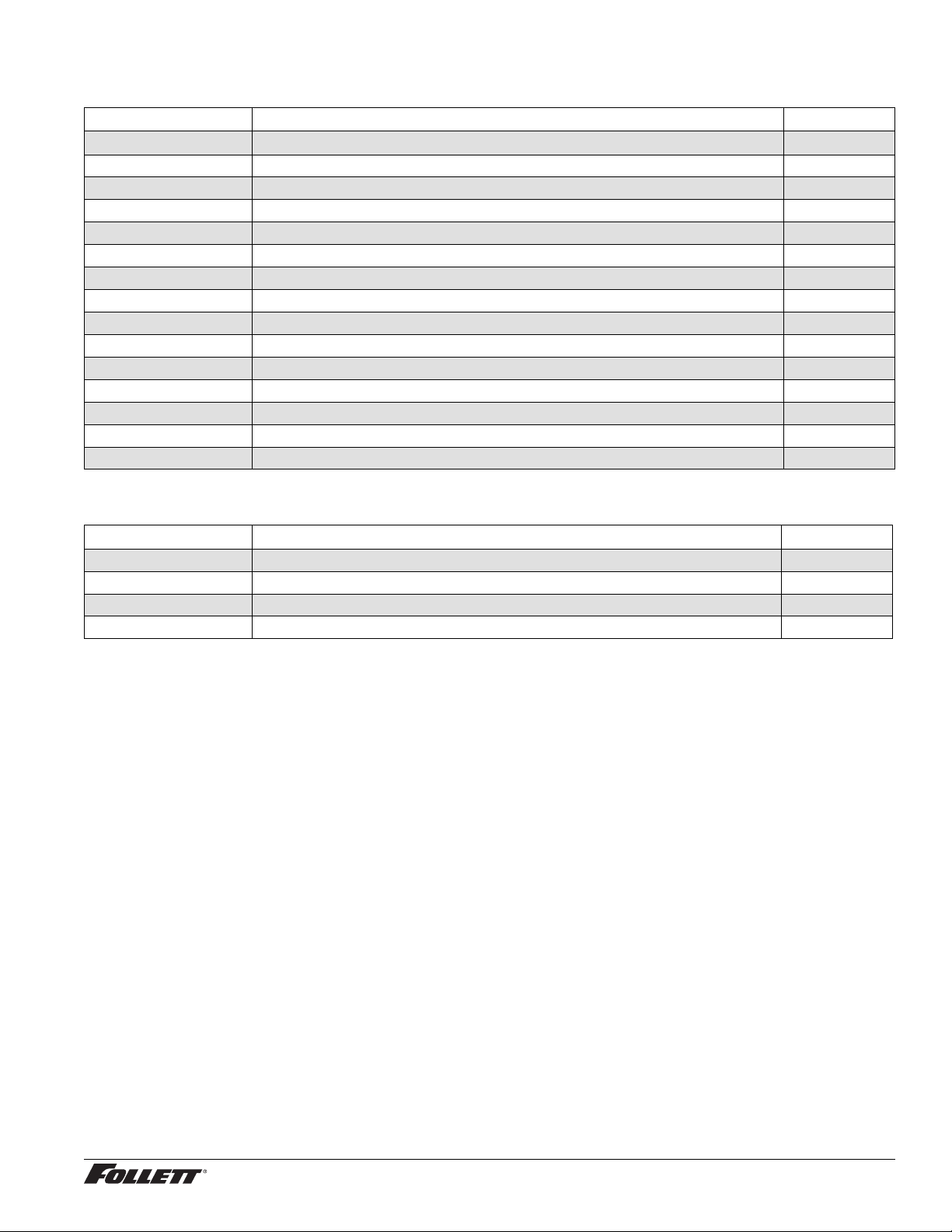
Evaporator Assembly
Reference # Description Part #
1 Gearmotor Assembly 00957811
2 Main Housing with Front Seal and Screws 00957829
3 Screws, Main Housing 00957837
4 Auger with front seal (includes gearmotor hardware kit) 00957845
5 Ice Compression Nozzle Assy 00957852
6 Front Seal and O-Ring 00957860
7 Evaporator Assembly with Insulation 00957878
8 Housing, Bushing with Insulation 00957886
9 Hardware kit, Gearmotor (For serial numbers E01087 and above) 01048628
9 Hardware kit, Gearmotor (For serial numbers below E01087) 00957894
10 Reservoir and Float Complete Assy 00957902
11 Lid, Reservoir with Insulation and O-Ring 00957910
12 Float Valve 00957928
13 “T” Fitting - 1/4" 502923
14 Tubing - 1/4" 502079
Miscellaneous
Reference # Description Part #
Not Shown Water lter cartridge, 5 micron 00968107
Not Shown Cleaning and sanitizing kit, single use 00979856
Not Shown SafeClean, case of 24 00132001
Not Shown IMS II sanitizer concentrate, 16 oz 00979674
Undercounter Dispenser and Ice machine 7UC100A/7UD100A 33
Page 34
34 Undercounter Dispenser and Ice machine 7UC100A/7UD100A
Page 35

Undercounter Dispenser and Ice machine 7UC100A/7UD100A 35
Page 36

SafeCLEAN is a trademark of Follett Corporation.
Follett is a registered trademark of Follett Corporation, registered in US.
801 Church Lane • Easton, PA 18040, USA
Toll free (877) 612-5086 • +1 (610) 252-7301
www.follettice.com
00966879R07
© Follet Corporation 8/13
 Loading...