

Folger Adam 310-4-30-12D-605-LCBMA, 310-4-30-12D-606-LCBMA, 310-4-30-12D-612-LCBMA, 310-4-30-12D-613-LCBMA, 310-4-30-12D-629-LCBMA Installation Instructions
...Page 1
Installation Instructions
Folger Adam 310-4-1, -2, -3, -30 Series Electric Strike
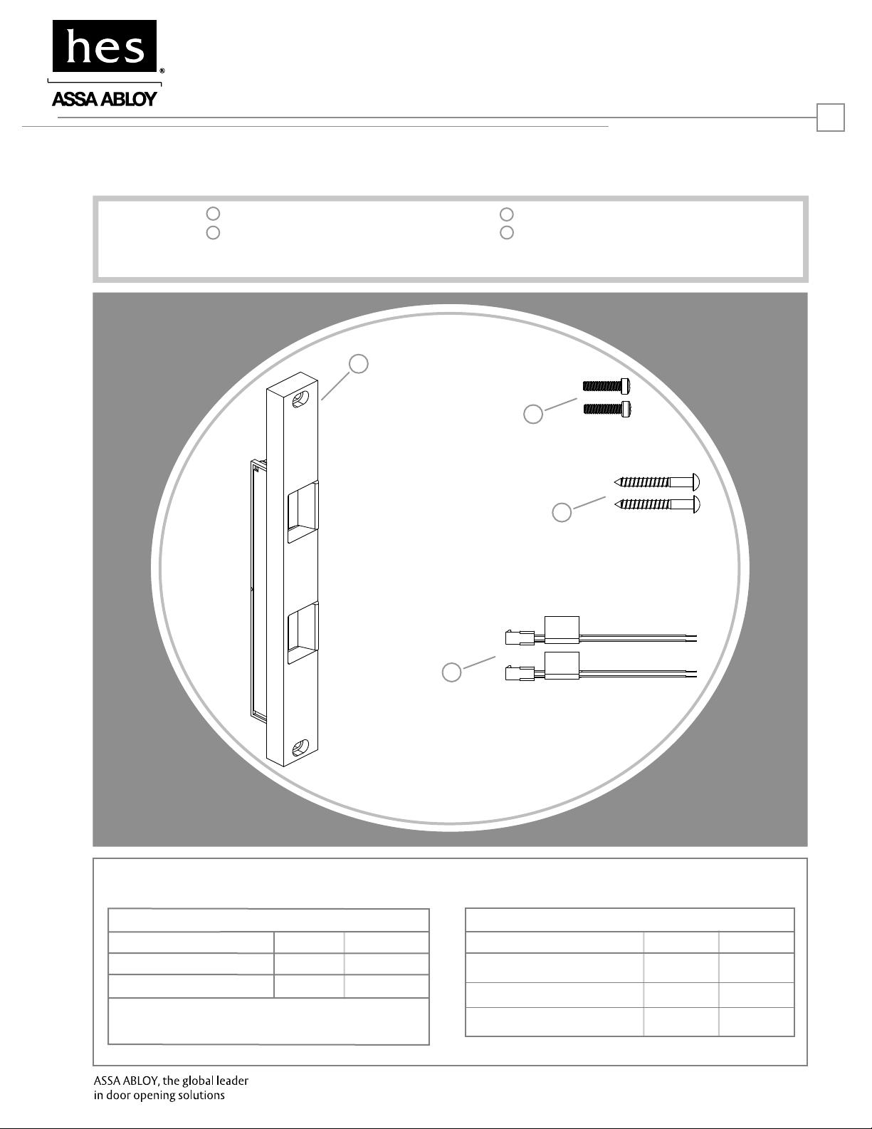
Product Components
1
Electric Strike Body & Faceplate
2
1/4-20 x 1” Mounting Screws
*Only 1 Plug In Connector is used with 310-4-30
1
HES, Inc.
22630 N. 17th Ave.
Phoenix, AZ 85027
800-626-7590
www.hesinnovations.com
3
#14 x 2” Mounting Screws
4
Plug In Connectors*
2
1
Electrical Specifications
ELECTRICAL RATINGS FOR SOLENOID*
CONTINUOUS DUTY
Resistance in Ohms
Amps
Solenoids are rated at +/- 10% indicated value.
*Resistance value indicated above is per coil.
12VDC
23.5
.51
24VDC
96
.25
3
4
MINIMUM WIRE GAUGE REQUIREMENTS
SOLENOID VOLTAGE
200 feet or less
200 - 300 feet
300 - 400 feet
12VDC
18 gauge
16 gauge
14 gauge
24VDC
18 gauge
18 gauge
16 gauge
Page 2
Installation Directions
CAUTION! Before connecting any device at the installation site, verify input voltage using a multimeter.
Many power supplies and low voltage transformers operate at higher levels than listed. Any input voltage exceeding
10% of the solenoid rating may cause severe damage to the unit and will void the warranty.
2
Prepare Strike
1. If using the LCBMA (Latchbolt Monitor & Locking Cam
Monitor), see Diagram 1 for wiring instructions.
2. The strike body ships as either a 12 or 24 volt
unit and is not field selectable. Verify the available
voltage is +/- 10% of the rated voltage of the strike body.
Prepare Frame
3. Prepare frame using the template for your strike
located on pages 3-4.
Finish Installing
4. Connect the Plug In Connector to the electric strike, and
connect wires from the Plug In Connector leads to the
power source.
5. Install the electric strike unit in jamb cutout, using the
1/4-20 x 1” mounting screws for metal applications, or
the #14 x 2” screws for wood applications.
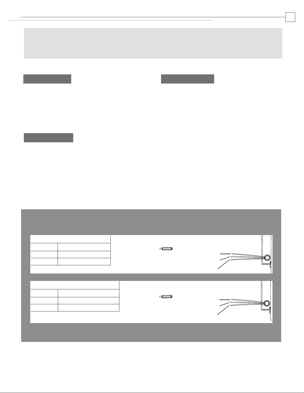
Diagram 1: Monitoring Switches
Latchbolt Monitor (LBM)
White
Orange
Green
Locking Cam Monitor (LCM)
Brown
Blue
Yellow
Common
Normally Open
Normally Closed
Common
Normally Open
Normally Closed
White
Orange
Green
Brown
Blue
Yellow
Page 3

Cutout Templates
310-4-1 Template & Dimensions
12-5/8”
"B
[320.68]
12-1/4”
"C "
[311.15]
C
L
4-3/8”
"A"
[111.13]
3-15/16”
[100.08]
C
L
Center line of electric
strike & latchbolt of
lock must align
3-15/16”
[100.08]
Reinforce jamb for tapped
holes (10 gauge minimum,
2 places)
3/16”
[4.75]
11/16”
[17.45]
1-5/16”
[33.32]
Drill & tap 1/4” x 20
thru (2 places)
2-3/4
(69.85)
1-5/8
(41.28)
4-1/2
(11.43)
13-3/8”
[339.73]
12-5/8”
[320.68]
4-3/8”
[111.13]
5/8
(15.88)
1-5/8
(41.28)
(11.43)
4-1/2
3/4
(19.05)
1-11/16
(42.86)
1-1/2
(38.10)
3/4
(19.05)
3
Inches [mm]
13-1/4”
"B
[336.55]
12-7/8”
"C "
[327.03]
3-15/16”
[100.08]
5”
"A"
[127]
C
L
Reinforce jamb for tapped
holes (10 gauge minimum,
2 places)
310-4-2 Template & Dimensions
2-3/4
(69.85)
3-15/16”
[100.08]
C
L
Center line of electric
strike & latchbolt of
lock must align
3/16”
[4.75]
11/16”
[17.45]
1-5/16”
[33.32]
Drill & tap 1/4” x 20
thru (2 places)
1-5/8
(41.28)
4-1/2
(11.43)
14”
[355.60]
13-1/4”
[336.55]
5”
[127]
5/8
(15.88)
1-5/8
(41.28)
(11.43)
4-1/2
3/4
(19.05)
1-11/16
(42.86)
1-1/2
(38.10)
3/4
(19.05)
Page 4

Cutout Templates
310-4-3 Template & Dimensions
13-7/8”
"B
[352.43]
13.5”
"C "
[342.90]
C
L
5-5/8”
"A"
[142.88]
3-15/16”
[100.08]
C
L
Center line of electric
strike & latchbolt of
lock must align
3-15/16”
[100.08]
Reinforce jamb for tapped
holes (10 gauge minimum,
2 places)
3/16”
[4.75]
11/16”
[17.45]
1-5/16”
[33.32]
Drill & tap 1/4” x 20
thru (2 places)
2-3/4
(69.85)
1-5/8
(41.28)
4-1/2
(11.43)
14-5/8”
[371.48]
13-7/8”
[352.43]
5-5/8”
[142.88]
5/8
(15.88)
1-5/8
(41.28)
(11.43)
4-1/2
3/4
(19.05)
1-11/16
(42.86)
1-1/2
(38.10)
3/4
(19.05)
4
Inches [mm]
11-1/4”
"B
[285.75]
10-7/8”
"C "
[304.80]
3-15/16”
[100.08]
3”
"A"
[76.2]
C
L
Reinforce jamb for tapped
holes (10 gauge minimum,
2 places)
310-4-30 Template & Dimensions
2-3/4
(69.85)
3-15/16”
[100.08]
C
L
Center line of electric
strike & latchbolt of
lock must align
3/16”
[4.75]
11/16”
[17.45]
1-5/16”
[33.32]
Drill & tap 1/4” x 20
thru (2 places)
1-5/8
(41.28)
4-1/2
(11.43)
12”
[304.80]
11-1/4”
[285.75]
3”
[76.20]
5/8
(15.88)
1-5/8
(41.28)
(11.43)
4-1/2
3/4
(19.05)
1-11/16
(42.86)
1-1/2
(38.10)
3/4
(19.05)
3810006.003 rev A
© 2010 HES, Inc.
 Loading...