

Page 1
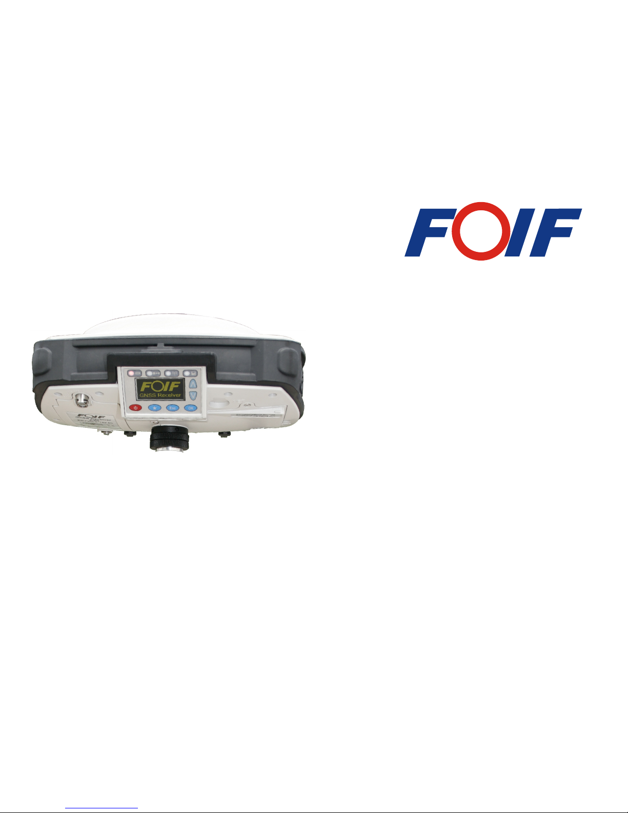
A20 GNSS Receiver
User Manual
Suzhou FOIF Co.,Ltd
Version 1.0
Page 2

System from FOIF! GNSS has revolutionized control surveys, topographic data collection
and construction surveying. Purchasing the right tools for a professional job is essential in
today's competitive business environment. Learning to put these tools to work quickly and
efficiently will be the focus of the present manual. Compared with other GNSS products,
exclusive multi-constellation (GPS+GLONASS+SBAS) capabilities. In addition because
it's easy to use, you will be able to focus on your job.
for all your GNSS survey operations!
Congratulations! You have just acquired the latest dual-frequency A20 GNSS Surveying
Introduction
A20 is more compact and lightweight while integrating more technology, such as the
No more cables, no more clip-on modules: A20 will be the reliable tool you are expecting
Page 3

Page 4

1 Summary
2 Unpacking the Container
2.1 Container Contents
2.2 Components of the PS236 Controller
3 Setting Up Receivers
3.1 Base Station
3.2 Setting Up Base Station by External Radio
3.3 External Radio
3.4 Power Amplifer
3.5 Rover Station
4 General Introduction
4.1 Nomenclature
4.2 Displayed Panel and Keyboard
4.3 Battery
5 Receiver Operation
Contents
5.1 Button
5.2 LED Indicating Lights
1
3
3
5
6
6
8
9
11
12
16
16
18
19
20
20
23
Safety Information
3.6 Measuring the A ntenna Heights
13
3.7 Controller Connecting
15
Page 5

6 Static Surveying
6.1 Process
6.2 Data Downloading and Format Converting
6.3 Ways of Outdoors Working for Static Surveying
6.4 GPS Network
35
35
35
38
39
46
46
46
47
48
7 Specifications
7.1 Physical Specifications
7.2 Positioning Specifications
7.3 Technical Specifications
7.4 Technical Specifications for Controller
5.3 Displayed Menu
24
Page 6
Safety Information
This manual describes the A20 GNSS Receiver.
Before you use your receiver make sure that you have read and understood this manual, as
well as all safety requirements.
WARNING
CAUTION
Ignoring this indication and making an operation error could
possibly result in death or serious injury to the operator.
Ignoring this indication and making an operation error could
possibly result in personal injury or property damage.
Regulations and safety
The receivers contain integra Bluetooth wireless technology, and may also send radio
signal through the antenna of an internal radio-modern, or through an externally-connected
data communication radio. Regulations regarding the use of the 460MHz radio-modems
vary greatly from country to country. In some countries, the unit can be used without
obtaining an end-user license. Other countries require end-user licensing. For licensing
information, consult your local FOIF dealer. Bluetooth operates in license-free bands.
Page 7

Exposure to radio frequency radiation
For radio (410~430MHz/430~450MHz/450~470MHz)
It is safety. Exposure to RF energy is an important safety consideration. Proper use of this
radio modem results in exposure below government limits.
The following precautions are recommended:
lDO NOT operate the transmitter when someone is within 20cm of the antenna.
lDO NOT collocate (place within 20cm) the radio antenna with any other transmitting
lDO NOT operate the transmitter unless all RF connectors are secure and any open
connectors are properly terminated.
lDO NOT operate the equipment near electrical blasting caps or in an explosive atmosphere.
lAll equipment must be properly grounded according to FOIF installation instructions for
safe operation.
lAll equipment should be serviced only by a qualified technician.
For GSM radio
CAUTION
- For your own safety, always observe the precautions listed here.
- Always maintain a minimum separation distance of 20cm between
yourself and the radiating antenna on the radio-modem.
- Do not collocate (place within 20cm) the radio antenna with any
other transmitting antenna.
antenna.
Page 8

For Bluetooth radio
The radiated output power of the internal Bluetooth wireless radio is far below radio fre-
quency exposure limits. Nevertheless, the wireless radio shall be used in such a manner
that the FOIF receiver is 20cm or further from the human body. The internal wireless radio
operates within guidelines found in radio frequency safety standards and recommendations,
which reflect the consensus of the scientific community. FOIF therefore believes the internal
wireless radio is safe for use by consumers. The level of energy emitted is far less than the
electromagnetic energy emitted by wireless devices such as mobile phones. However, the
use of wireless radios may be restricted in some situations or environments, such as on
aircraft. If you are unsure of restrictions, you are encouraged to ask for authorization before
Installing antennas
CAUTION
- For your own safety, always observe the precautions listed here.
- Always maintain a minimum separation distance of 20cm between
yourself and the radiating antenna.
- Do not collocate (place within 20cm) the radio antenna with any
other transmitting antenna.
turning on the wireless radio.
Page 9

This device has been designed to operate with the antennas listed below.
UHF Antennas not included in this list, or that have a gain greater than 5dBi, are strictly
prohibited for use with this device. The required antenna impedance is 50 ohms.
The antennas that can be used (country dependent) with the 460 MHz radio are 0dBi and
5dBi whip antennas.
The antenna that can be used with the GSM radio is the 0dBi whip antenna.
To reduce potential radio interference to other users, the antenna type and its gain should
be so chosen that the equivalent isotropic ally radiated power is not more than that permitted
for successful communication.
Rechargeable Lithium-ion batteries
These receivers use a rechargeable Lithium-ion battery.
WARNING
- Do not damages the rechargeable Lithium-ion battery. A damaged
battery can cause an explosion or fire, and can result in personal
injury and /or property damage. To prevent injury or damage:
- Do not use or charge the battery if it appears to be damaged. Signs
of damage include, but are not limited to, discoloration, warping,
Page 10
and leaking battery fluid.
- Do not expose the battery to fire, high temperature, or direct sun-
- Do not immerse the battery in water.
- Do not use or store the battery inside a vehicle during hot weather.
- Do not drop or puncture the battery.
- Do not open the battery or short-circuit its contacts.
WARNING
- Avoid contact with the rechargeable Lithium-ion battery if it is
appears to be leaking. Battery fluid is corrosive, and contact with it
can result in personal injury and/or property damage.
To prevent injury or damage:
- If the battery leaks, avoid contact with the battery fluid.
- If battery fluid gets into your eyes, immediately rinse your eyes with
clean water and seek medical attention. Do not rub your eyes!
- If battery fluid gets onto your skin or clothing, immediately use
clean water to wash off the battery fluid.
WARNING
light.
Page 11
WARNING
- Charge and use the rechargeable Lithium-ion battery only in strict
accordance with the instructions. Charging or using the battery in
unauthorized equipment can cause an explosion or fire, and can
result in personal injury and/or equipment damage.
To prevent injury or damage:
- Do not charge or use the battery of it appears to be damaged or
- Charge the Lithium-ion battery only in FOIF product that is spe-
cified to charge it. Be sure to follow all instructions that are pro-
vided with the battery charger.
- Discontinue charging a battery that gives off extreme heat or a burn-
ing odor.
- Use the battery only in FOIF equipment that is specified to use it.
- Use the battery only for its intended use and according to the
instructions in the product documentation.
Other Warning
WARNING
- Operating or storing the receiver outside the specified temperature
range can damage it.
For more information, refer to 9. SPECIFICATION.
leaking.
Page 12

A20 is regarded as an highly integrated, semi-open structure and modular designed RTK
system independently researched by FOIF. GNSS antenna,data link, GPRS/CDMA,Li-Ion
which is convenient in the products maintainance and upgrade. Stable industry standard
two data transmission ways (GPRS/CDMA, data Link),we can use 3G function of the
With high accuracy, fast tracking function of inner GNSS mainboard,A20 can track the
satellite signal as more as 220 channels simultaneously.
Highly sealed, waterproof, dustproof, shockproof, low power consumption are its basic
inspecting rules. With super and weatherable OLED screen built on A20 receiver, the real
1 Summary
battery, memory device, bluetooth etc. are all focused in one receiver. Moreover, GNSS
antenna, datalink and battery are independently modules which are easy to replace thus
handheld for A20 has inner or external GPS antenna and camera for optional function to
upgrade this handheld to a GIS collector. 3G memory device is also optional for the hand-
held, thus can further upgrade to a highly accurate GIS collector. Meanwhile, besides the
mobile phone to do the RTK job, in this way, we can say A20 has already existed in 3G
time information of the receiver can be shown on the screen. 4 lights and 6 buttons are
easily used to set the receiver, and the voice aided is helpful to the outdoors surveying.
Downloading and backups of the static data could be convenient because of the inner SD
slot, thus resolves your trouble for the insuffcient memory.
A20 User Manual
1
period.
Page 13

is no problem but also for the compatability in the CORS of other companies. In order to
fulfill the characteristic of compatability in A20, inner radio can easily be upgraded to be
compatible with GNSS products of other companies in the RTK field. The electric power
design for A20 is also very advanced, large capacity of Li-Ion batteries(4400mAh) can
on both external and internal charging ways. A20 can also be used by external DC power
A20 is widely used for control survey,engineering survey,topography survey,GIS,boundries
location, area survey, deformation monitoring etc. And from the education subjects based
also be used on the total station (810 series) made by FOIF. These batteries are depended
on GNSS products, you can also find A20.
A20 User Manual
2
Due to its advanced compatability, static surveying with GNSS products of other companies
(7-18V).
Page 14
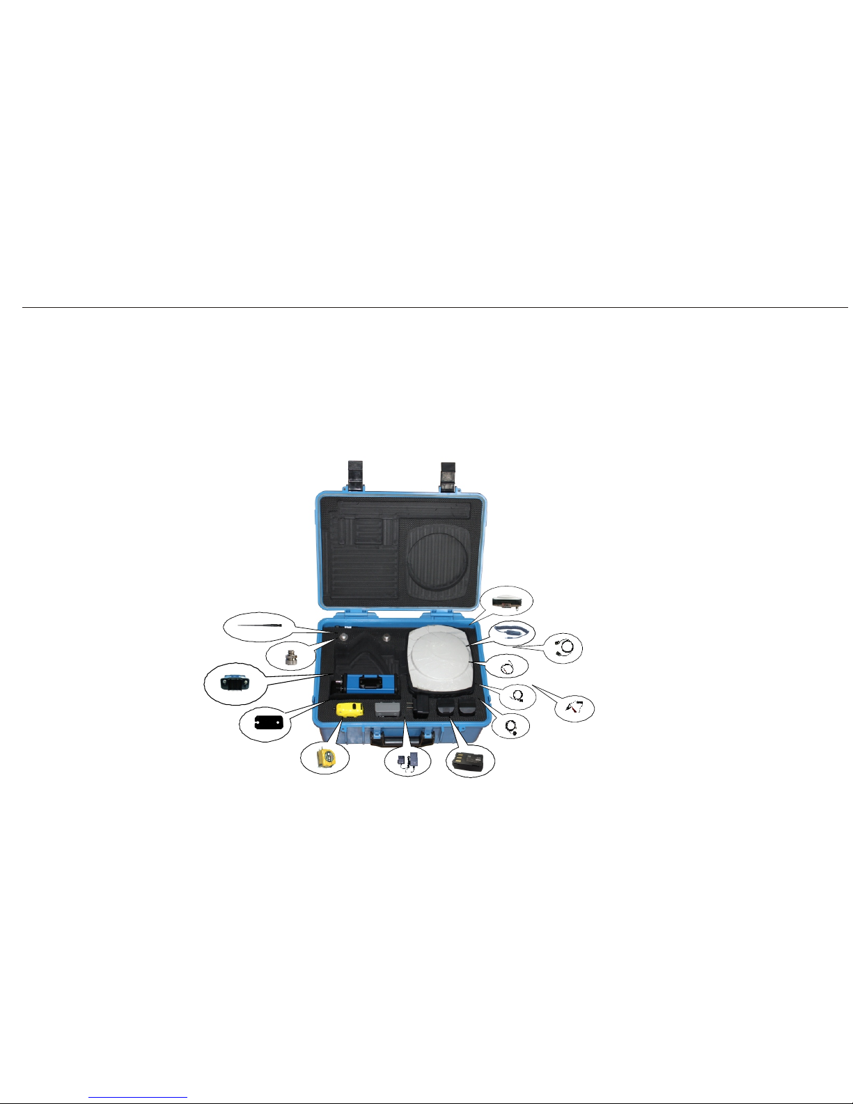
2 Unpacking the Container
2.1 Container Contents
The main components required for the cableless GNSS real-time system are combined in
one transport container.
A Base
B Charger (car)
A
B
C
D
E
F
G
H
I
J
K
L
M
N
C Charging cable (1.5m)
D Transferring cable
E RF cable (2.8m)
F Connecting line (RS232)
G Connecting cable between
storage and receiver
H Battery
I Charger
J Tape
K Plate
L Radio (Optional)
M Connector
N UHF antenna
Base Container
Description
Container for
A20
and delivered
accessories
part 1 of 2
A20 User Manual
3
Page 15
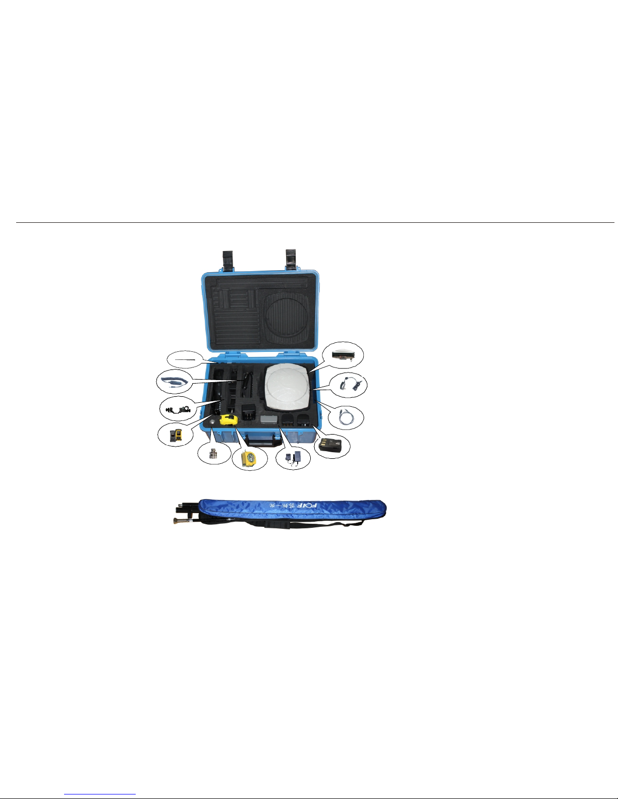
A
B
C
D
E
F
G
H
I
J
K
Rover Container
A Rover
B Charger for controller
C Connecting line for controller
D Battery
E Charger
F Tape
G Connector
H PS236
I Bracket
J Charger (car)
K UHF antenna
L
M
L Pole
M Enhanced UHF antenna
Detailed information can check from A20 equipment list.
Container for
A20
and delivered
accessories
part 2 of 2
A20 User Manual
4
Page 16
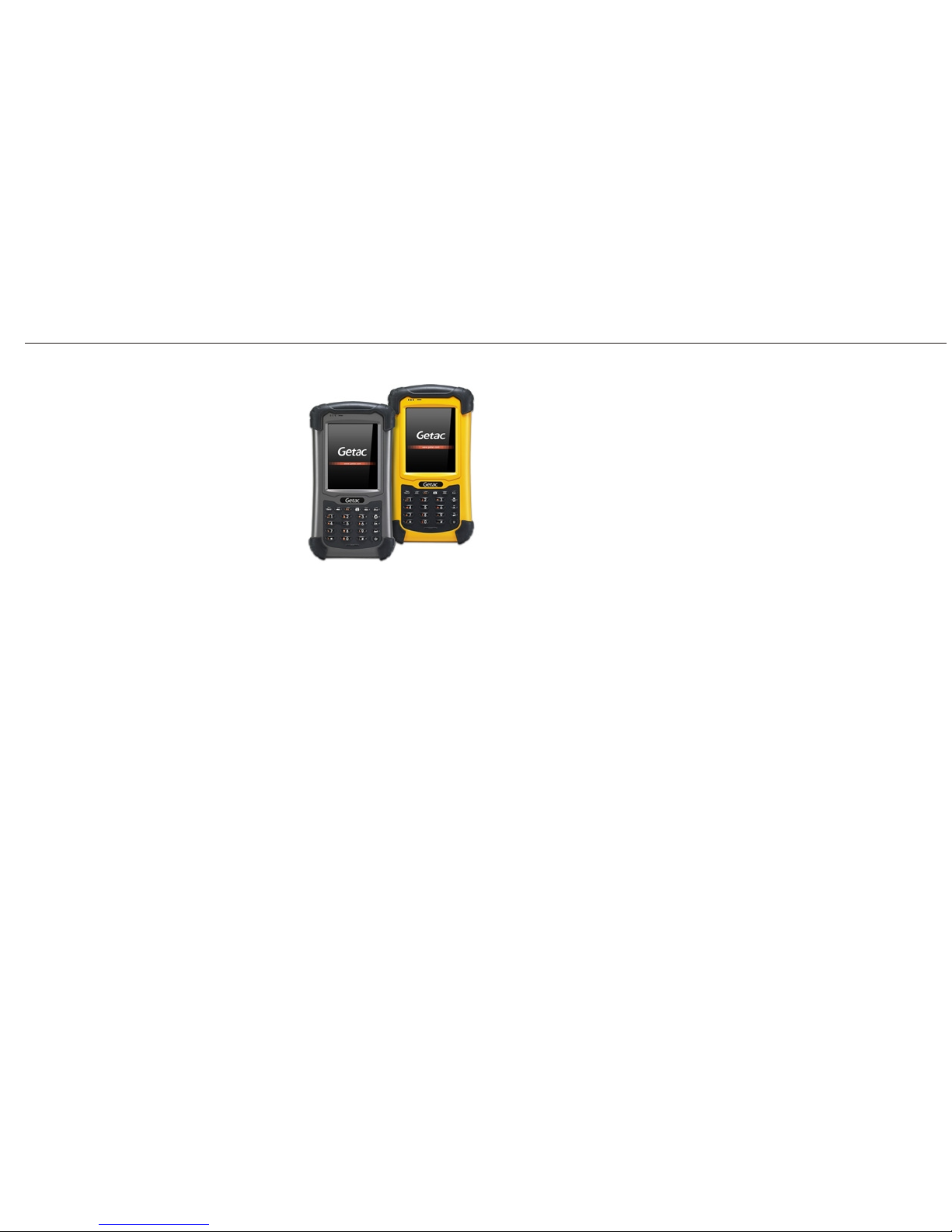
a) Microsoft Windows Mobile 6.1 OS
b) 3.5inch transflective sunlight readable LCD
c) Embedded high sensitivity GPS receiver
d) MIL-STD-810G and IP67 compliance
e) Long battery life provides all-day power
f) 3G function is supported
2.2 Components of the PS236 Controller
PS236
A20 User Manual
5
Page 17
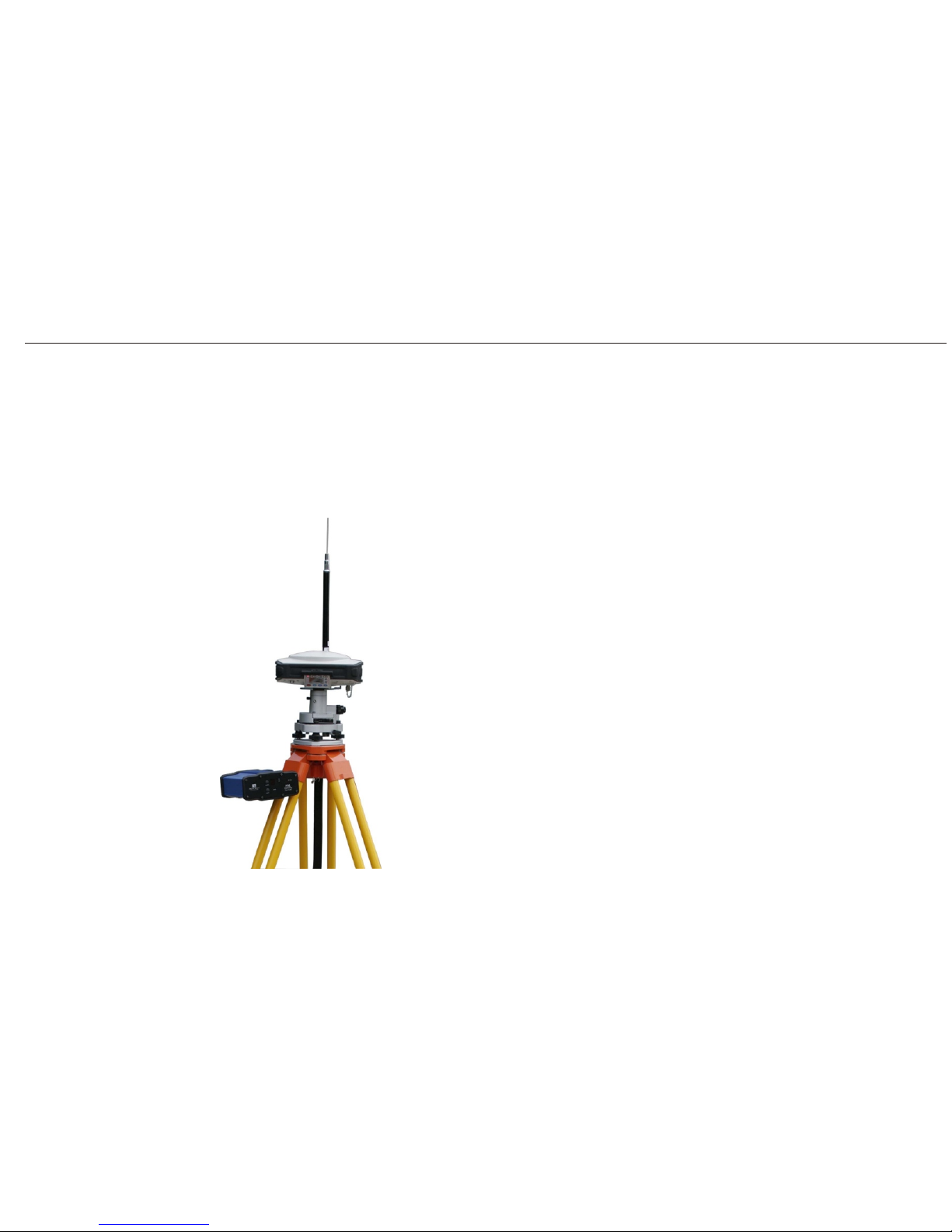
Base
Picture showing
real-time
base station
setup
Choose a suitable place for your base station setting up.
1) The place for base station setting up should be wide opened and easy to receive the
2) Higher place would be better for setting up, thus signal of UHF is easy to receive. If
is far from base, then the enhanced antenna should be raised by using bipod.
signal of satellites.
3) Base should be far away from the high power WiFi objects,e.g. radio,
MWS etc. Distance between them needs to be more than 200m. And
less than 50m from power lines is also forbidden to set up base.
Process:
1. Set up the tripod mount and level the tribrach onto the tripod.
2. Check that the tribrach is correctly centred over the marker.
3. Place and lock the receiver on the tribrach.
4. Check that the tribrach is still correctly positioned and leveled.
5. Choose external radio module from FOIF Survey_GPS software.
6. Fix the radio beside tripod, using cable FG-DB9-M to do the
*
7. Fix enhanced UHF antenna.
connection work between radio and receiver.
A20 User Manual
3 Setting Up Receivers
3.1 Base Station
6
rover
Page 18

Notice:
lWhen plugging in an cable with ODU plug, make sure that the red dots on the receiver
port and the cable connector line up. Do not use force to plug cables in, as this may da-
mage the connector pins.
lWhen disconnecting an cable with ODU plug, grasp the cable by the sliding collar or
lanyard and then pull the cable connector straight out of the port. Do not twist the
connector or pull on the cable itself.
lTo securely connect a TNC antenna, align the antenna connector with the receiver
receptacle and then thread the antenna connector onto the receptacle until it is snug.
lAvoid the following sources of electrical and magnetic noise:
a) Gasoline engines (spark plugs) b) Televisions and PC monitors
c) Alternators and generators d) Electric motors
e) Equipment with DC-to-AC converters f) Fluorescent lights
g) Switching power supplies
lAvoid exposure to extreme environmental conditions, including:
a) Water
b) Heat than 65
c) Cold less than -30
d) Corrosive fluids and gases
8. Connecting radio and storage with cable FDL-1-1 and cable FDL-1-2.
*
*
check from A20 equipment list
A20 User Manual
7
Page 19
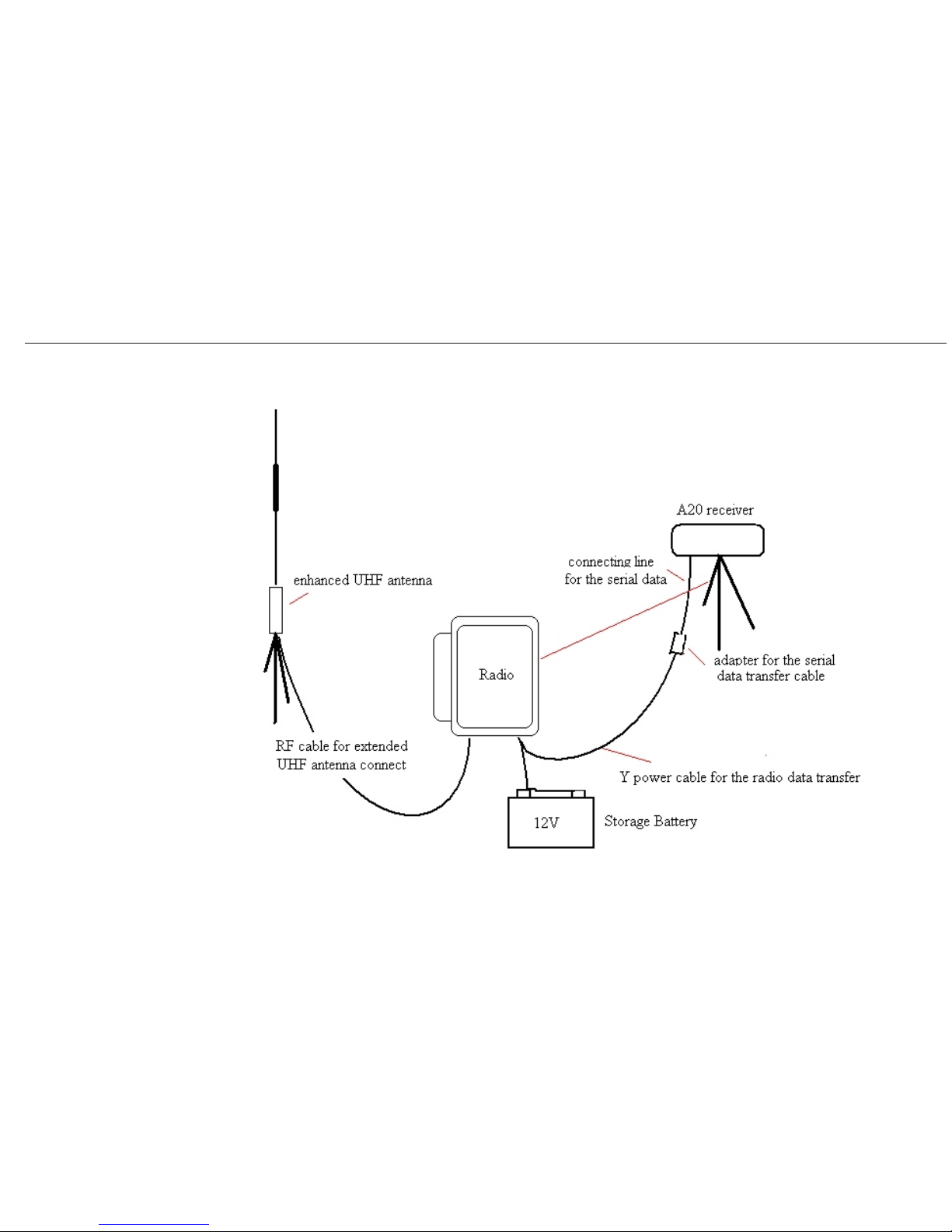
Two tripods
supported
A20 User Manual
3.2 Setting Up Base Station by External Radio
8
Page 20
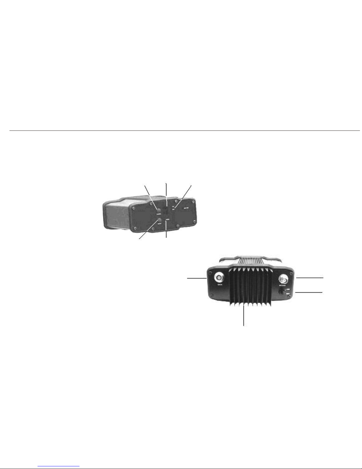
Channel
0~9&A~F
Channel
displayed
Signal
light
Power
Power
light
Data input
&battery supplied
Heat sink
Antenna port
Button for
power setting
Frontal panel (buttons and channel displayed )
Back panel (ports detailed)
PCC radio
A20 User Manual
9
3.3 External Radio
Page 21

Notice:
1) Connection should be tight between every part(cable,radio,receiver) to com-
firm the successful data transferring.
2) Storage battery used should distinguish the positive and negative poles to avoid
the electric short circuit.
3) Suggested brand of storage battery is Panasonic, other brands such as camel,
fengfan ect. are also accepted as long as the output voltage is 12V and power
comsumption is not less than 17Ah.
4) 5m pole is suggested in raising the UHF antenna for better signals.
5) Distance between UHF antenna and A20 should be more than 3m.
6) Considering the safety of yours, A20 is not suggested to be used at the weather
of thunder or storms.
A20 User Manual
10
Page 22
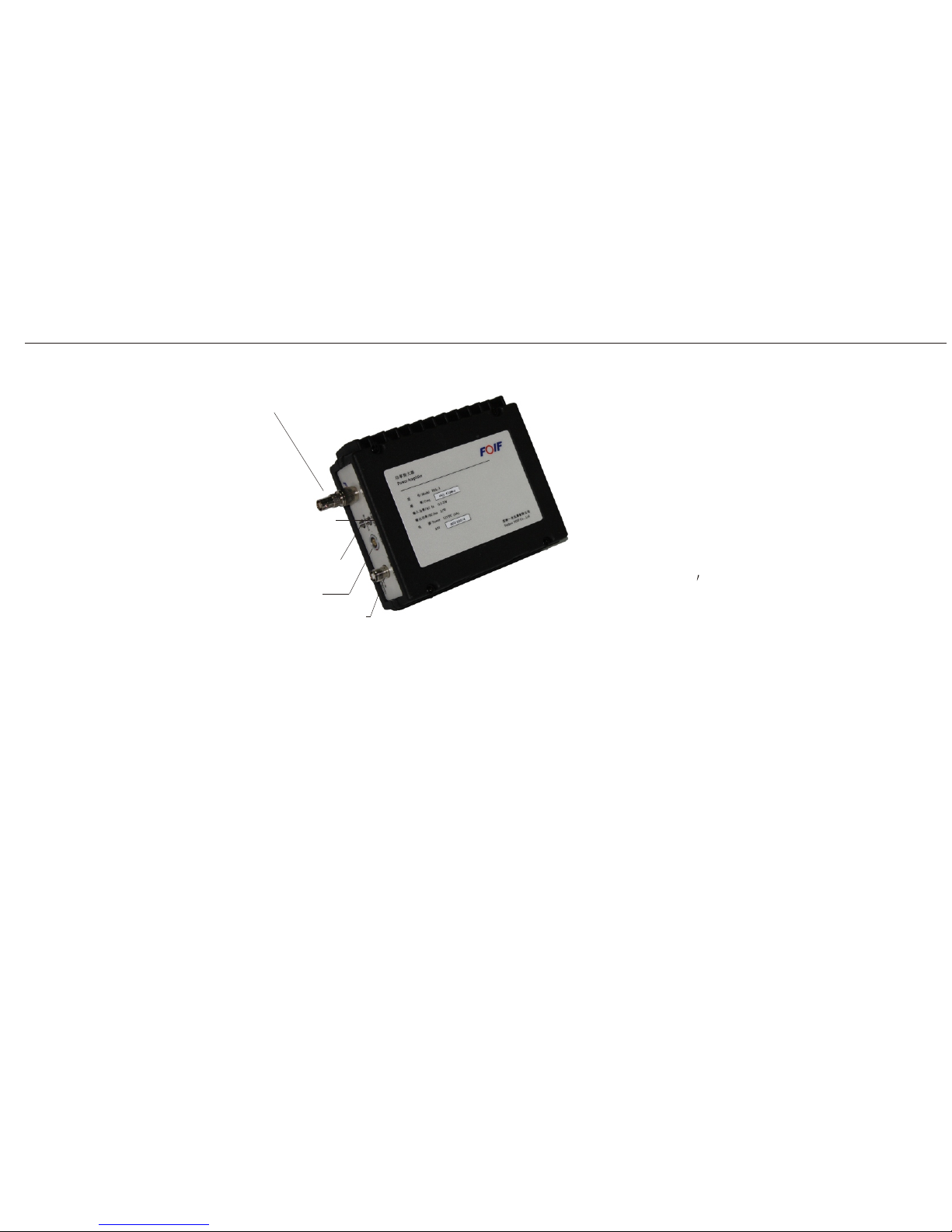
A20 User Manual
11
Function:
Power Amplifer can enlarge transferring
Port for ANT
PWR Light
DATA Light
PWR Port
Port for RF.IN
distance which is the same function as
external radio, but should work together
with A20 which has inner emitting radio.
Because A20 has many Product Numbers to
choose for deciding its configuration. So if
your A20 doesn
then Power Amplifer is not suitable, only
external radio.
t have inner emitting radio,
Notice:
1) Connection should be tight between every part(cable,radio,receiver) to comfirm
the successful data transferring.
2) Storage battery used should distinguish the positive and negative poles to avoid
the electric short circuit.
3) Comfirm that the antenna is connecting with the Power Amplifer before emitting
4) Finish working, make sure to stop emitting the data firstly, then remove the cable.
3) and 4) are all benefic for protecting the Power Amplifer.
Made by FOIF
the data.
3.4 Power Amplifer
Page 23
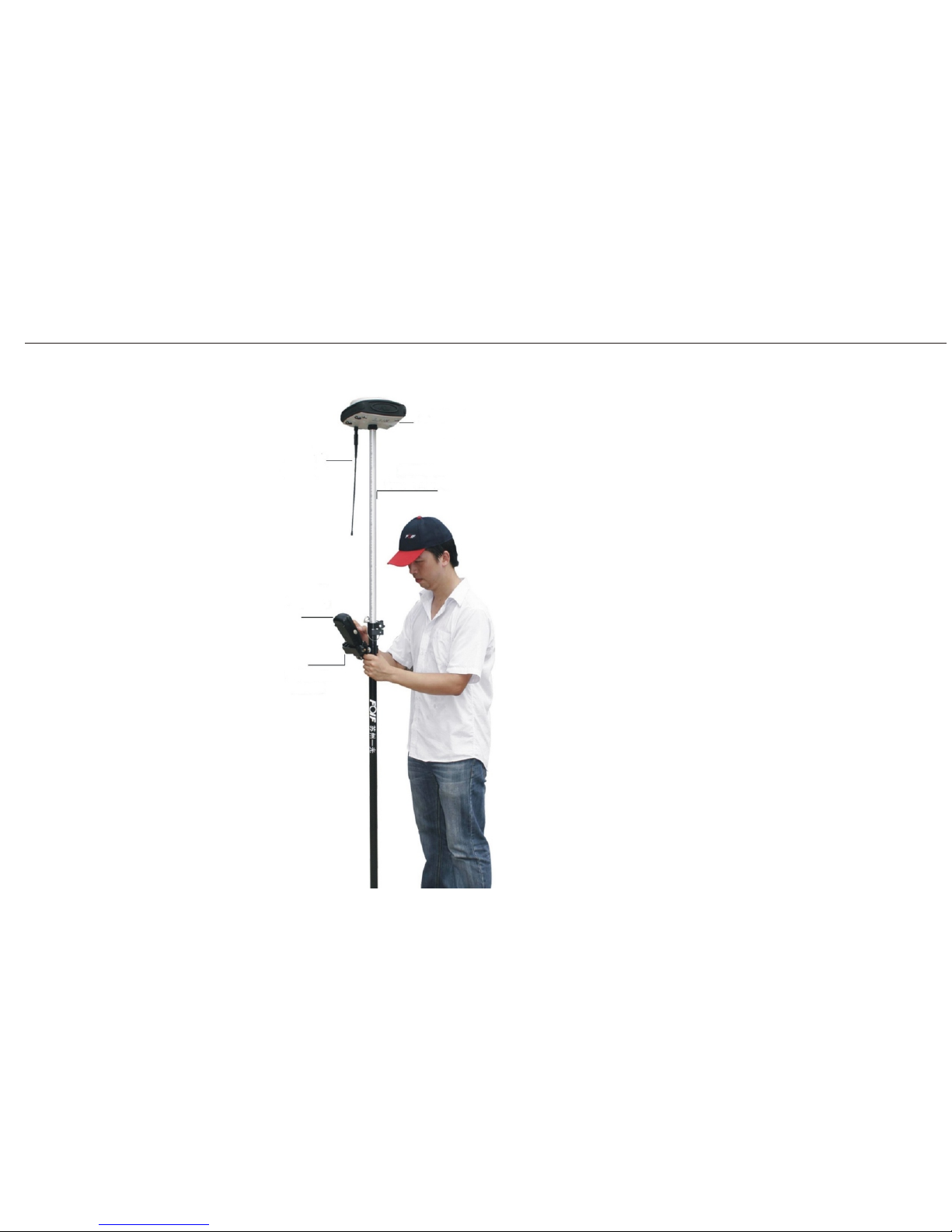
receiver
UHF antenna
telescopic pole
controller
bracket
Notice:
1. If telescopic pole is used, height of receiver
can be got directlly from the pole.
2. Comfirm that connection between bracket
and controller is tight to avoid that controller
dropping to the ground.
3. If network is used, then UHF antenna does not
need to fix on A20.
Picture showing
real-time
rover station
setup
A20 User Manual
Process:
1. Thread the receiver onto the pole.
2. Attach the controller bracket to the pole.
3. Insert the controller into the bracket.
3.5 Rover Station
12
Page 24
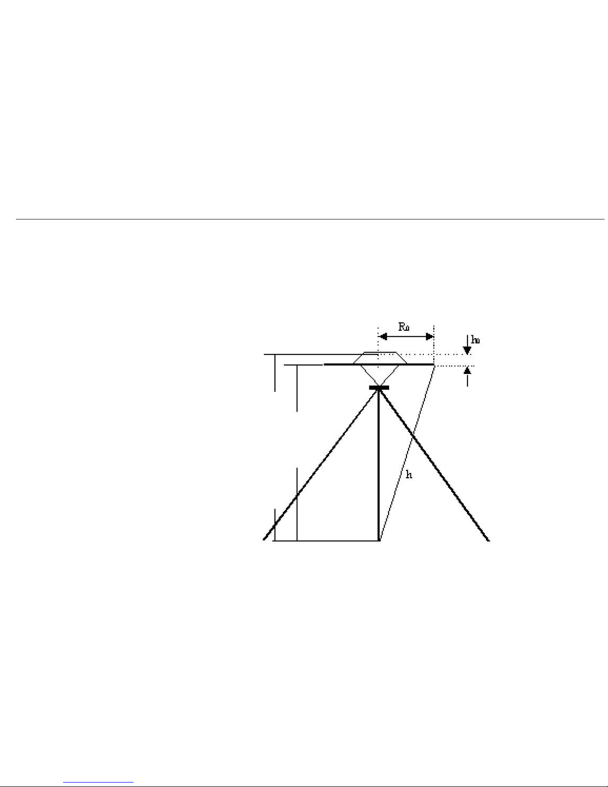
3.6 Measuring the Antenna Heights
3.6.1 Measuring the Antenna Heights for a Tripod Setup
Ways: Pay attention to the buckle of black rubber fixing around the receiver, use your
tapeline from the buckle to the point where your base is setting up, thus the reading
on tapeline is the height of base.
Height
of
DPCA
vertical
(slant)
Height of DPCA=Vertical+h0
A20 User Manual
13
Measuring the
antenna heights,
a quick overview
Page 25
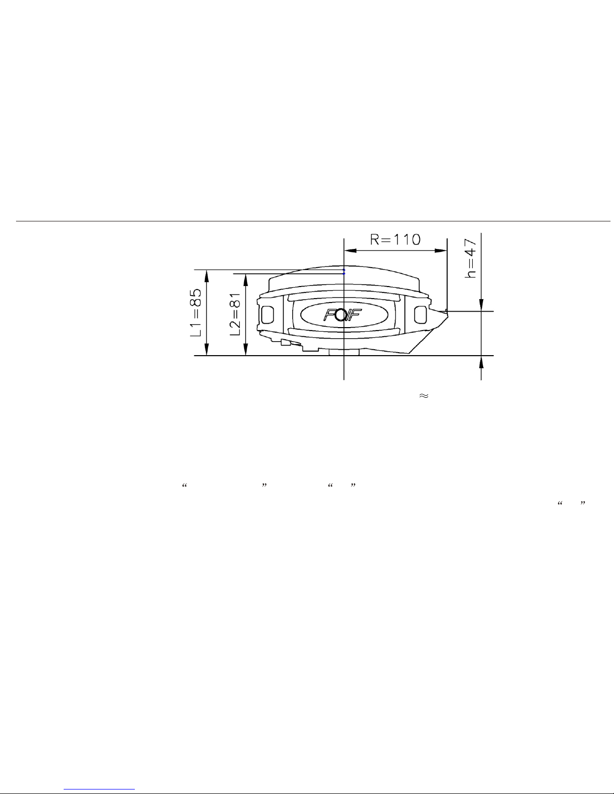
Parameter of A20 antenna: h0=(L1+L2)/2-h 54.3mm R0=R=110mm
3.6.2 Measuring the Antenna Heights for a Pole Setup
Height of rover=pole(2m)+h0
Considering the normal height of pole is 2m, so while setting the rover, you just only
choose vertical height and enter 2m , which is also the default choice, h0 could be
add automatically by software (FOIF Survey_GPS). If telescopic pole is used, then 2m
should be changed to the actual height of pole.
A20 User Manual
14
Page 26
3.7 Controller Connecting
Two ways are supported connecting between controller and A20, bluetooth and RS232.
3.7.1 Bluetooth
1. Connecting work should be done first before start FOIF survey_GPS. Using controller
scan the bluetooth signal of A20.When bluetooth is found, the SN of A20 is shown in
controller, then select this SN to finish the connecting work.
2. Set port (No. of port can be searched from bluetooth settings in controller.) and baud rate
of controller to finish connecting.(More shown in FOIF_survey User Manual)
3.7.2 RS232
Using serial port cable to build the connection by setting the port with COM1 and baud rate
with 19200.
3.7.3 State of Connecting Shown
When connection is successful whether by bluetooth or RS232, you can comfirm from the
screen of A20. or would be displayed on the screen, means RS232 while
means bluetooth.
3.7.4 Disconnecting
Menus in FOIF Survey_GPS software, Configuration Com configuration, you can stop
the connecting work by selecting the other COM port. While doing so, A20 receiver is still
working normally, but you can not control the receiver by using your controller.
A20 User Manual
15
Page 27
4 General Introduction
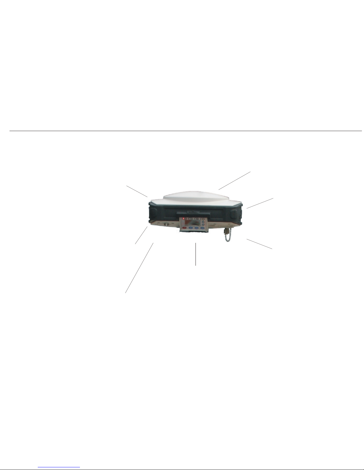
4.1 Nomenclature
Frontal panel
upper cover
inner antenna
shockproof rubber ring
(anticorrosion)
port for the antenna
of inner radio
displayed/operating
interface
lower cover
battery/SIM card/
slot for SD card
A20 User Manual
16
Page 28
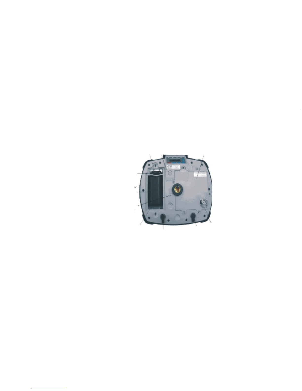
Bottom of
panel
fixed system
of phase center
slot for
SIM card
speaker
communication
module
SD card
Lithium-Ion battery
(4400mAh)
place for battery
COM1(handheld connecting)
/DC IN
COM2(external radio)
/DC IN
port for the antenna
of inner radio
A20 User Manual
17
Page 29
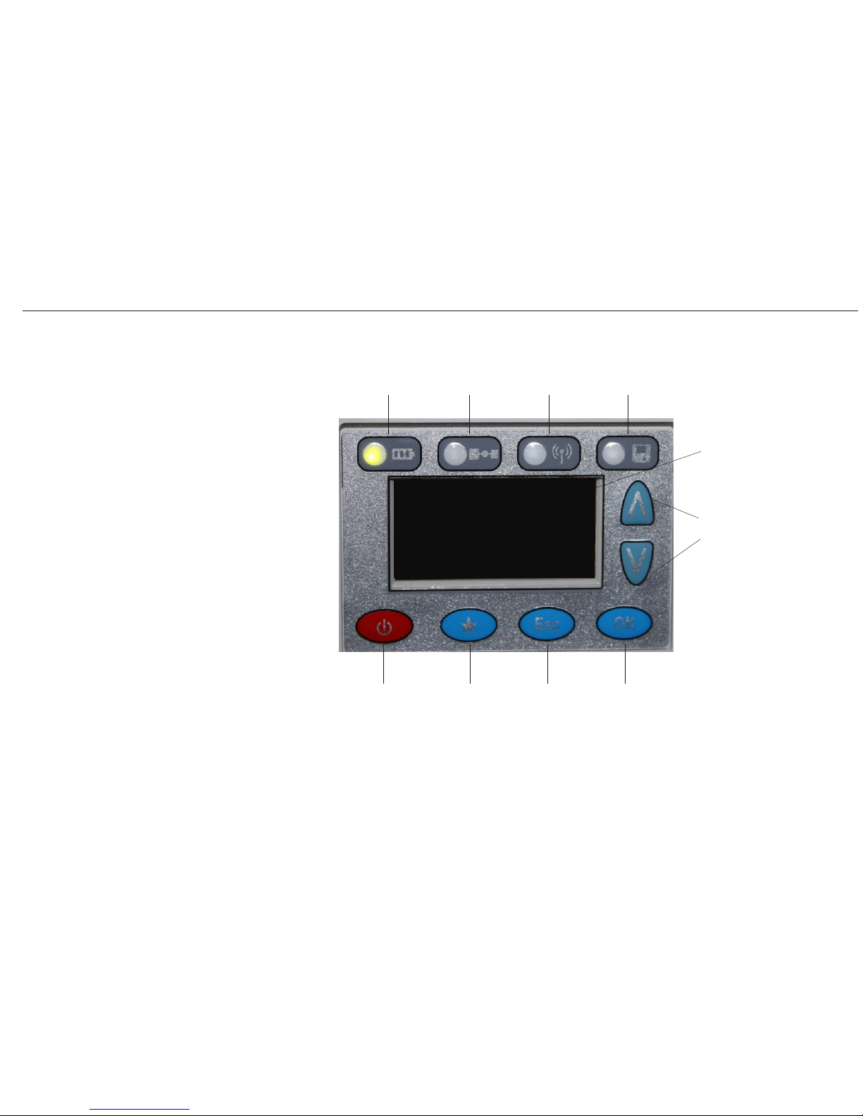
A20 User Manual
OLED Screen
4.2 Displayed Panel and Keyboard
18
BAT SAT
LINK
REC
OLED
Up
Down
ENT
ESCHot Button
PWR
Page 30

Two ways are supported in battery supplied: inner Li-Ion battery or external storage battery.
While using the inner Li-Ion battery mode, capacity of battery would be displayed on the
screen by real-time detection. Charging time for Li-Ion battery should normally be less
A20 User Manual
Working time for A20 is more than 10 hours due to its high capacity chargable Li-Ion battery.
(but actual using time mayhave certain difference because of different environments)
A20 can be supported by external storage, the cable for connecting A20 and PC is standard
in A20 equipment list.
4.3 Battery
4.3.1 Ways of Battery Supplied
4.3.2 Supplied by Inner Li-Ion Battery
4.3.3 Supplied by External Storage
than 6 hours.
19
Page 31
5 Receiver Operation
5.1 Buttons
5.1.1
Power (red)
Function:
1 Turn on/off
Turn on
1)Confirm that A20 is at shutdown state.
2)Press ,then loosen it.
3)Start screen would be displayed on the screen of A20.
4)You can hear the voice while turning on A20.
5)Light(BATT) is on and light(GPS) is blinking.
6)Finish.
A20 User Manual
Turn off
1)Comfirm that A20 is at working state.
2)Press for about 3 seconds unless you hear the voice while the information lossen
the power button, the receiver will be closed ,then lossen button.
3)The screen and lights on it would all be closed.
4)Finish.
20
Page 32
5.1.2
Hot button
Function: 1 Start base station(including coordinate setting) according to last base station
settings.
2 Gain current coordinate instead of last coordinate of base station to set it
according to last link settings.
3 Start rover station according to last rover station setting.
4 Static state.(REC light is blinking instead of LINK light.)
Start:
1)Comfirm that A20 is not at the static state.
2)Comfirm that at least 4 satellites are tracked.(That is to say the GPS light is blinking
green continuously at least 4 times.
3)Press , then choose the item that you want to set by , then press .
4)Wait for a moment, you will see the blue light is blinking, indicating that data link
A20 User Manual
is successful (send or receiver), start surveying.
the item (base or rover) to achieve the result of your operating by the next time turning on
Notice:
If A20 is restored to factory setting, then you should turn off receiver after you have started
the receiver.
21
OKOK
Page 33
5.1.3
Esc
Function:
1)Cancle without setting.
2)Return to the previous menu.
5.1.4
Enter
Function:
1)Comfirm the settings.
2)Go to the next menu.
5.1.5
Up and down.
1)Up or forward.
2)Down or backward.
A20 User Manual
Notice:
In order to avoid misoperating, you should press the button for about 1 second to achieve
your choice. If the item you want to choose is not the next item (e.g. 3 or 4 items after the
cursor
s current position), then you can press without stop until the cursor switch to the
item you want.
22
OKOK
EscEsc
Page 34
A20 User Manual
5.2 LED Indicating Lights
5.2.1
Battery (green)
Function: Power Indicator.
1)>60%, green light is on without blinking.
2)40% ~60%, flash one time for every second.
3)20% ~40%, flash two times for every second.
4)10% ~20%, flash four times for every second.
5.2.2
Satellite (green or red)
Function: Display the number of satellites tracked by A20.
1)While blinking in red, indicating that A20 is searching the signals of satellites.
2)While blinking in both red and green, the times that the light blinks in green shows the
number of satellites tracked by A20.
5)<10%, A20 speaks to you.
5.2.3
Link (green)
Function: Differential Signal Indicator.
1)OFF: no signals transferring.
2)Blink regularly: normally sending or receiving signals.
3)Blink unregularly: unreliable in difference link.
23
Page 35
5.2.4
Record (green)
Function: Static working mode.
1)OFF: no static surveying.
2)Blinking regularly: Static surveying, the speed of blinking is the setting interval
5.3 Displayed Menu
5.3.1 Start Screen
A20 User Manual
recording.
24
Page 36
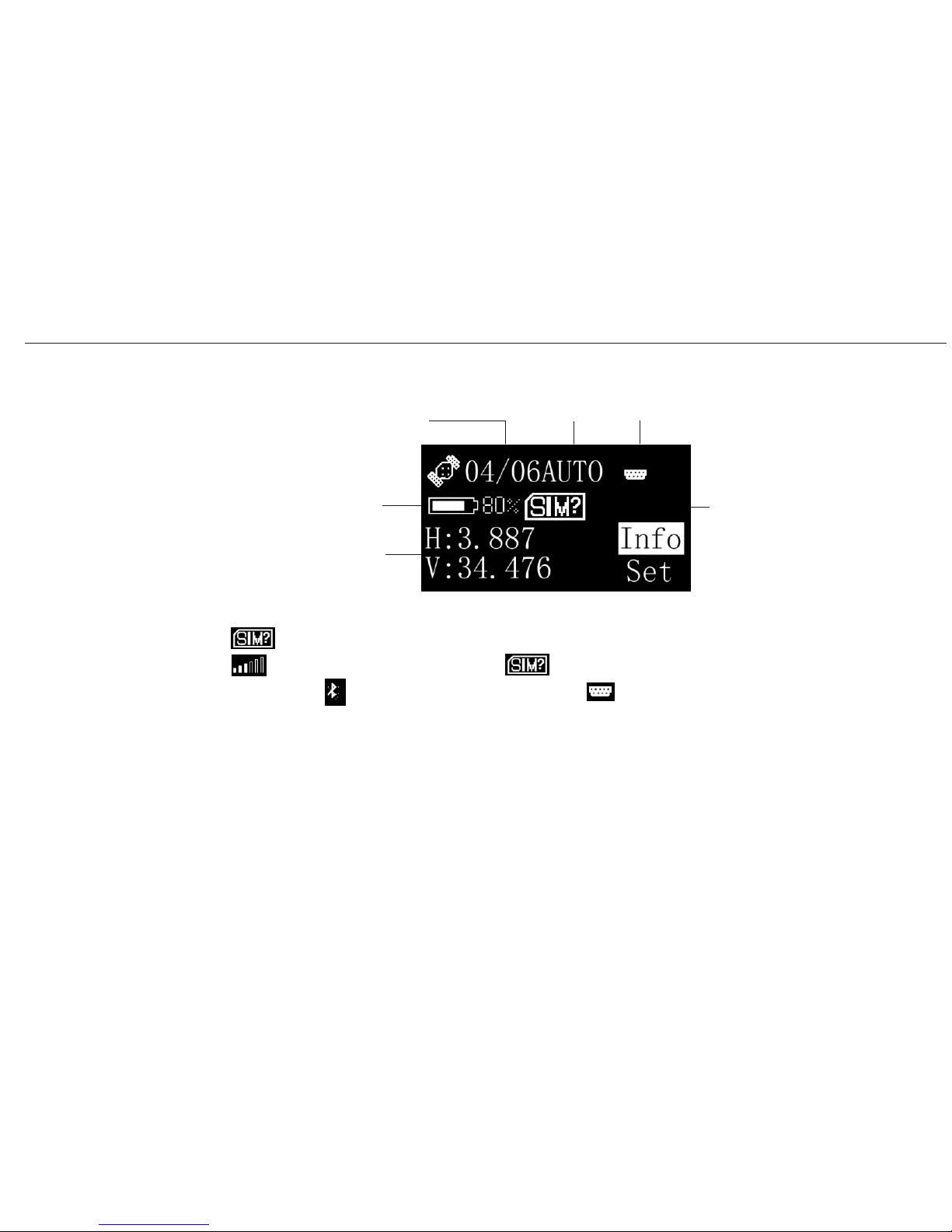
5.3.2 Main Interface
number of satellites
state of A20
COM/bluetooth
battery indicator
current accuracy
SIM card Info
indicates that SIM card is not in the receiver. If SIM card is put into the receiver,
would be displayed instead of . If receiver is connected to the controller by
bluetooth, would be displayed instead of which is the COM port symbol.
A20 User Manual
25
Page 37
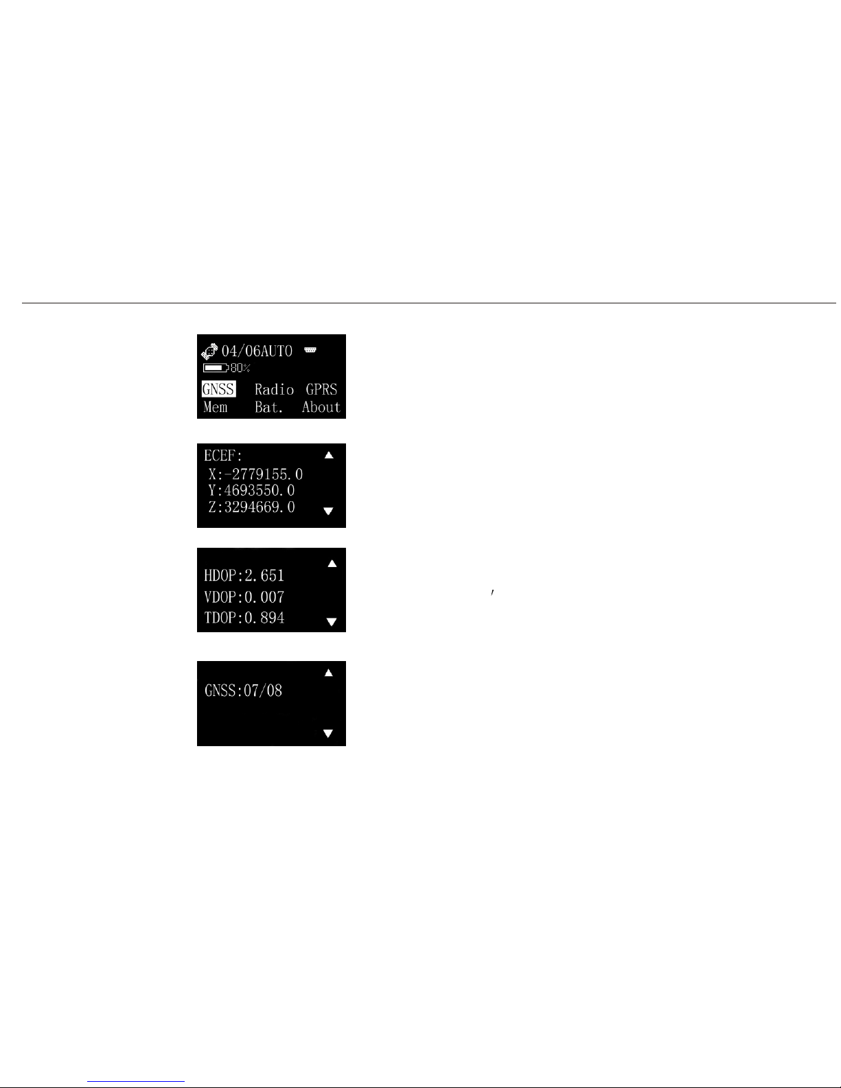
5.3.3 Menus in A20
Select Info. at the main interface, you will see the options like GNSS,
Radio, GPRS, Mem, Bat. and about.
Select GNSS, you will see the followed 3 interfaces. Switch them
Coordinate
Quality of satellites
by up or down arrow.
signals
Number of satellites tracked
A20 User Manual
Operating
Menu (1)
Info menu
Info/GNSS/P1
Info/GNSS/P2
Info/GNSS/P3
26
Page 38
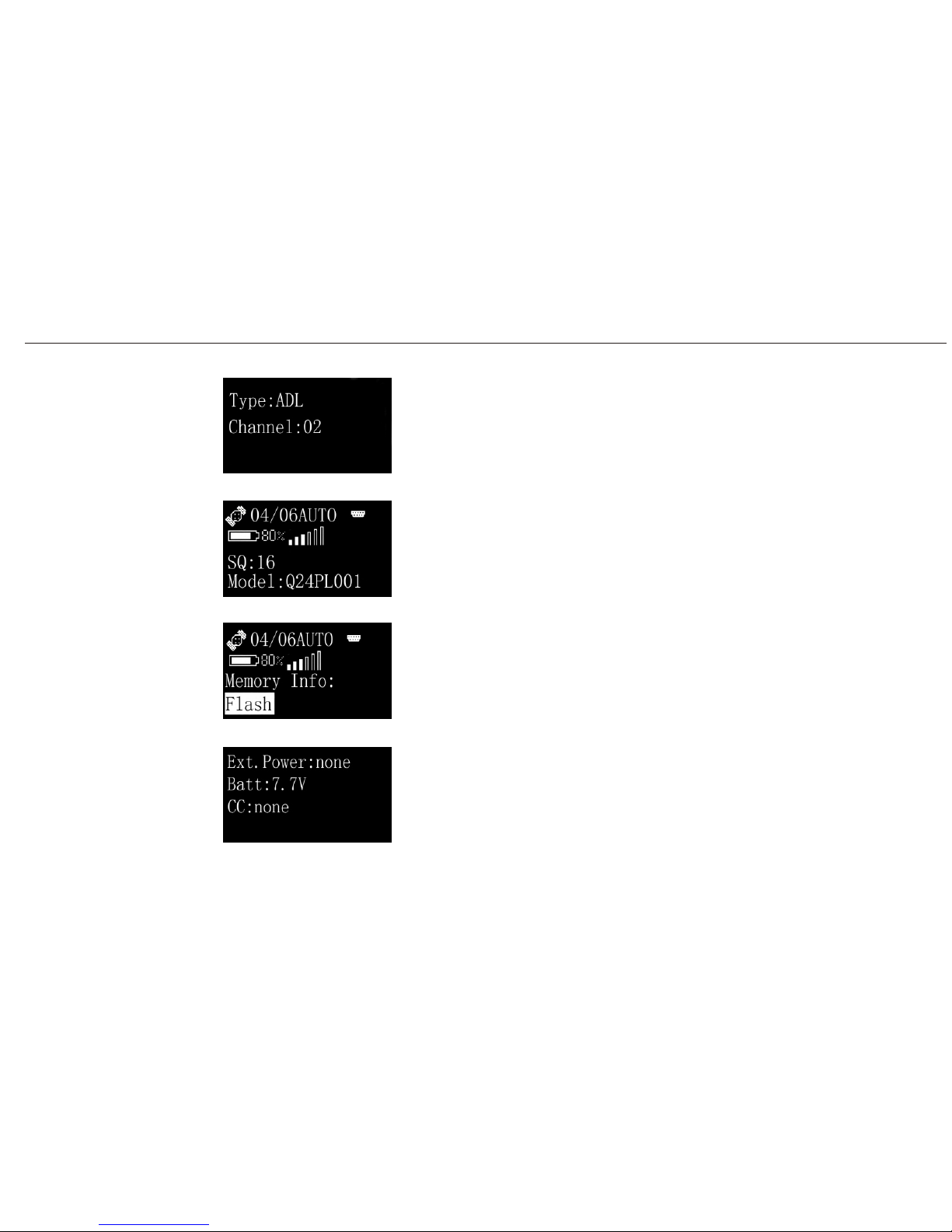
Select Radio, you will see the model and channel of radio.
Select GPRS, you will see the model and signal of GPRS.
Select Mem, you will see the Info. of memory.
Select Bat. , you will see the Info. of battery.
A20 User Manual
Operating
Menu (2)
Info/Radio
Info/GPRS
Info/Mem
Info/Bat.
27
Page 39
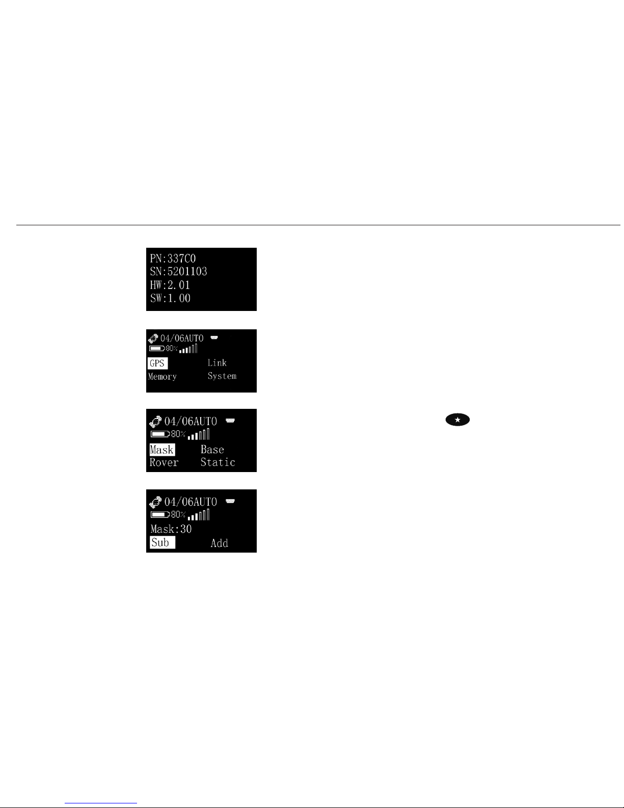
Select About, you will see the Info. of A20 such as PN, SN, edition
of software and hardware.
At the main interface, if you choose Set, you will see the setting
options for A20 such as GPS, Link, Memory and System.
Choose GPS, you will see four options for your setting such as Mask,
Base, Rover, Static.
Select Mask, here you can set the mask of A20.
A20 User Manual
Operating
Menu (3)
Info/About
Set menu
Set/GPS (same function as hot button )
Set/GPS/Mask
28
Page 40
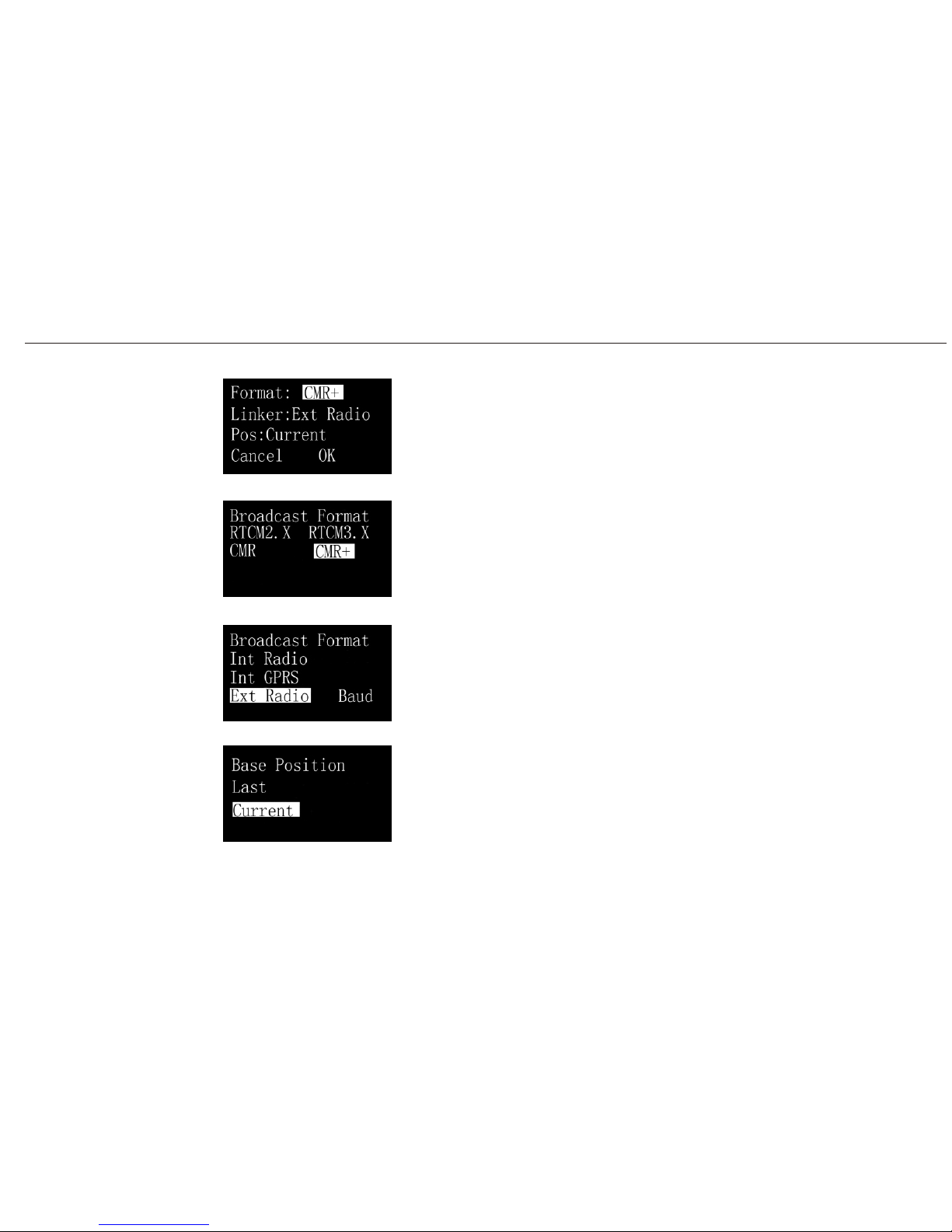
If you choose base, then you have many options for your base setting
such as Format, Linker and Position.
In the Format column, you can choose the most suitable format for
your surveying.
In the Linker column, you can choose the module of different linkers.
In the Pos. column, you can choose the coordinate of base position.
If the base has not moved, you can choose Last for the position of
base. Instead, you can choose Current for the position of base. But
be sure to do the coordinate converting because the accuracy of base
in current mode is 10m by AUTO state.
A20 User Manual
Operating
Menu (4)
Set/GPS/Base
Set/GPS/Base/Format
Set/GPS/Base/Linker
Set/GPS/Base/Pos
29
Page 41
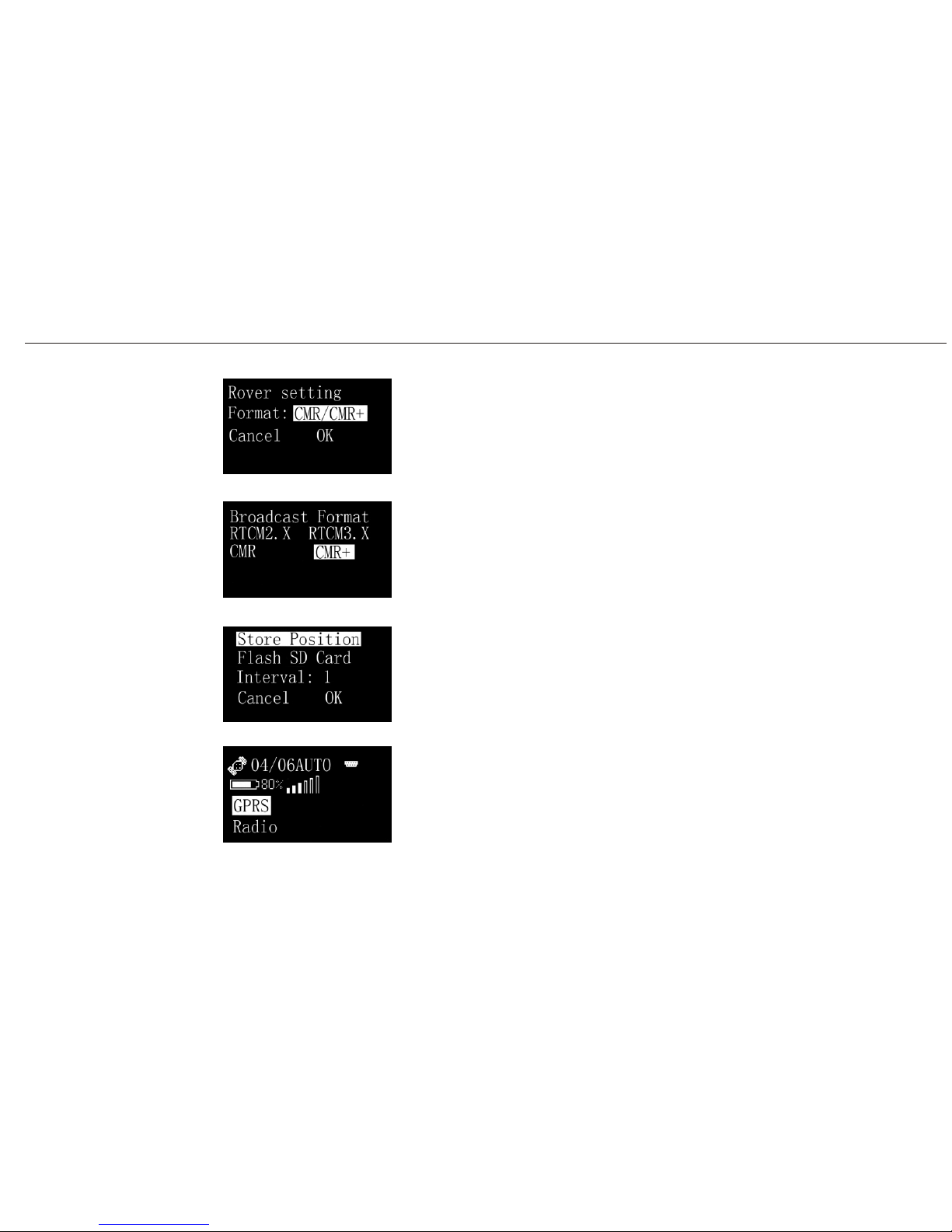
Choose Rover for your rover setting.
At the rover setting menu, you can select the format e.g. CMR etc.
If you choose Static, then 2 options for your setting such as Store
position and Interval. Two ways are available for your menory,
NAND flash and SD card.
If you choose link, then you would have two ways for your data
transferring.(GPRS and Radio)
A20 User Manual
Operating
Menu (5)
Set/GPS/Rover
Set/GPS/Rover/Format
Set/GPS/Static
Set/Link
30
Page 42
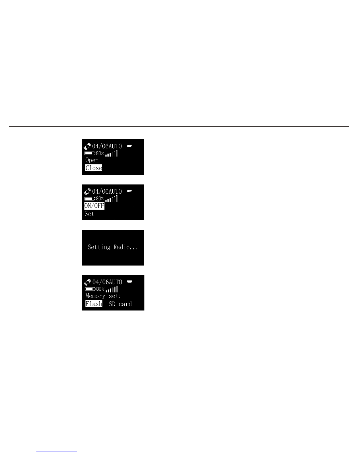
You can either Open or Close the GPRS linking.
This is the Radio(inner radio) setting interface.
Select Set, you would see the Setting Radio procedure.
You can also choose Memory to set it for storage medium.
(Flash or SD card)
A20 User Manual
Operating
Menu (6)
Set/Link/GPRS
Set/Link/Radio
Set/Link/Radio/Set
Set/Memory
31
Page 43
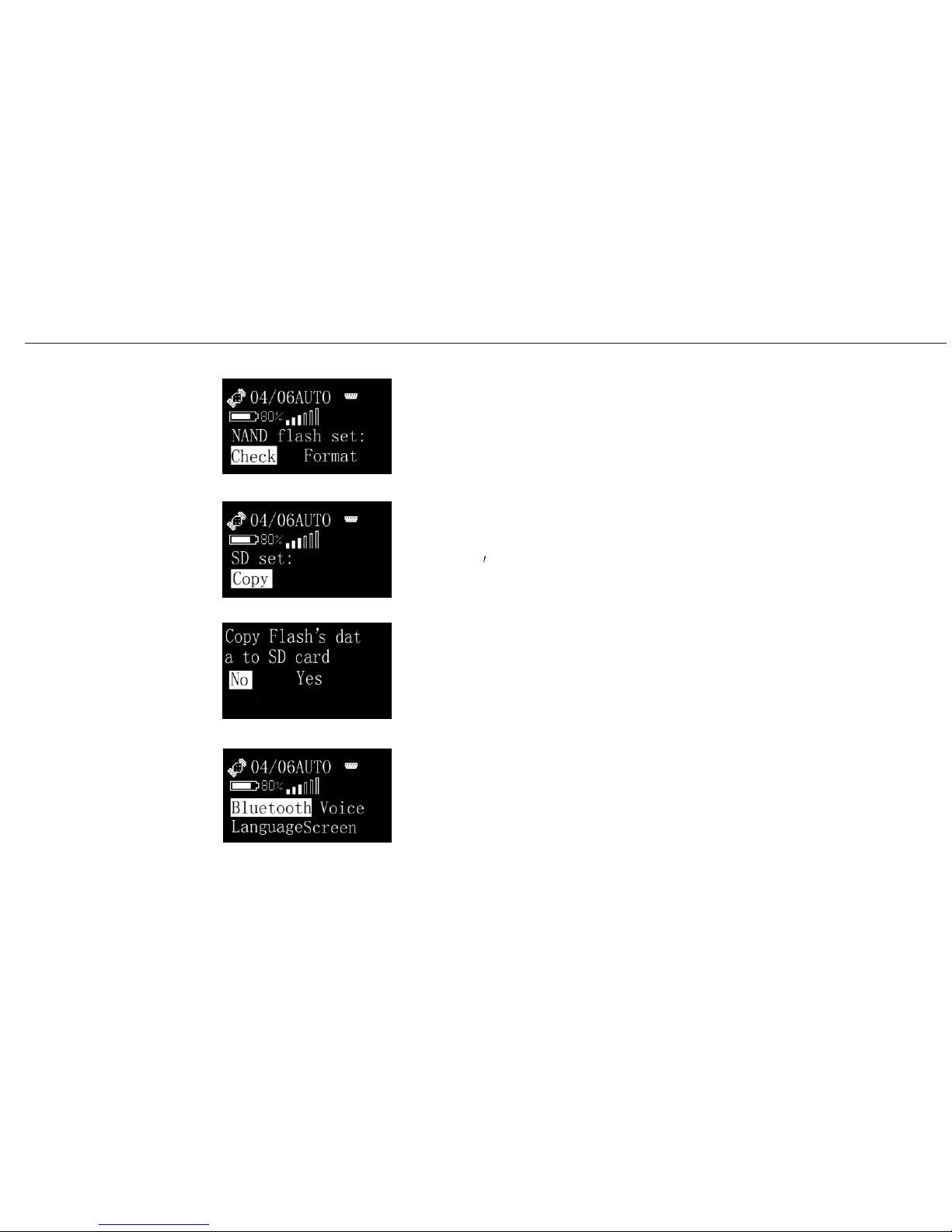
You can Check or Format NAND Flash.
If you choose SD card as memory, then you would be mentioned to
copy Flash
s data to SD card.
This is the copying procedure.
In the System menu, you have 4 options to set.
Bluetooth, Voice, Language and Screen.
A20 User Manual
Operating
Menu (7)
Set/Memory/Flash
Set/Memory/SD card
Set/Memory/SD card/Copy
Set/System
32
Page 44
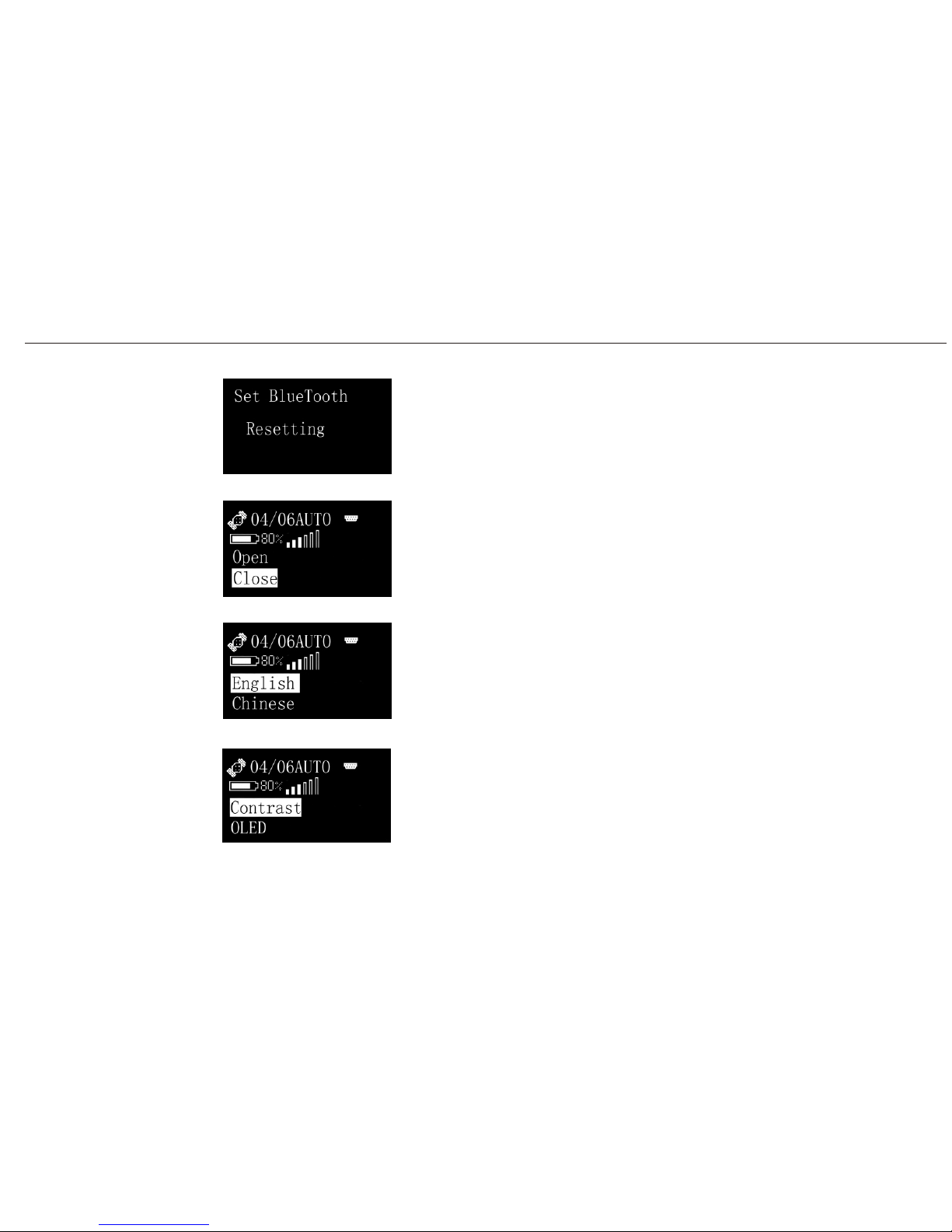
This is the Bluetooth Resetting procedure.
Here you can Open or Close the Voice.
Two options are available for language.
Screen to set Contrast and OLED.
A20 User Manual
Operating
Menu (8)
Set/System/Bluetooth
Set/System/Voice
Set/System/Language
Set/System/Screen
33
Page 45
A20 User Manual
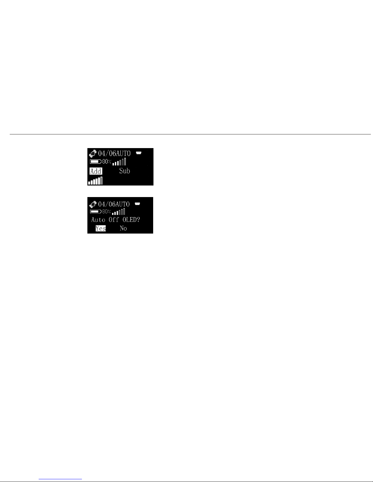
Choose Add or Sub to set the contrast of the screen.
This is power saving mode by choosing OLED, then you would be
asked whether auto off OLED or not. If you choose Yes, the screen
would be Off automatically after 1 minute without affecting your
Operating
Menu (9)
Set/System/Screen/Contrast
Set/System/Screen/OLED
surveying job.
34
Page 46

6 Static Surveying
A20 also has static surveying function, which includes outdoors surveying and office
6.1 Process
1) Fix A20 on tripod.
2) Measure the height of A20.
3) Turn on A20 while more than 4 satellites are tracked by this instrument, then start the
static surveying from the buttons of A20 screen.
4) It is important to record the surveying time, SN of A20,height of A20, etc. on a notebook
5) When outdoors surveying is over, turn off A20.
Notice:
Normally, it is better to record the static data on SD card.
6.2 Data Downloading and Format Converting
1) Connecting A20 and PC for data downloading.
2) File name given should according to the notes of outdoors surveying made by yourself.
SN of A20, surveying time and point name should all be indicated in the file name for
your easy distinction. For example, A20, the detailed information is,A200000086(SN
A20 User Manual
35
while this receiver is doing the static surveying.
working.
Page 47

surveying at 11am to 12am on CPI0027. So then we can give its name as 0027086B which
is different from 0023086A,although we use the same receiver to do the job.(The front 4
3) Convert these data to RINEX format and input the height of A20. You can finish this by
the software FOIFGNSS shown below.
numbers are point name, the later numbers are SN of receiver, the last capital letter is
can give its name as 0023086A. Further more, still this receiver for the second time
A20 User Manual
36
of receiver) for the first time surveying at 9am to 10am on CPI0023(point name), so we
surveying time.)
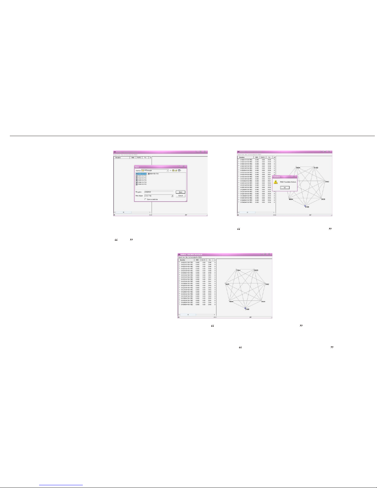
4) Click Import raw files for translated to RINEX , choose the files that need to be
converted.(These files are downloaded from receivers.) This software can convert as
much as 16 files at the same time.
5) Choose the files that you want to convert, then click Open . The converted files are
saved at the same path as your original files on your PC.
Page 48
A20 User Manual
37
7) When you have seen the window information RINEX Translation finished , then
press OK , you can see the network and baselines for your static surveying.
Detailed pictures are shown below,
8) Using FOIF post processing software FGO Geomatic Office 2008 to do the office
Detailed ways are shown in the user manual of FOIF Geomatics office 2008 .
work.
Page 49

6.3 Ways of Outdoors Working for Static Surveying
1) Surveyors should give a general understanding about their surveying district e.g. point
position, difficulties of making point and also includes the economic level, culture
custom, traffic situation etc. at that place.
2) Ephemeris forecast: Good surveying opportunities should depend on the surveying
position and the latest satellite ephemeris. The satellite ephemeris includes many aspects
e.g. visibility of satellites, satellite constellation, PDOP etc. If big building is beside the
A20 User Manual
38
point, then you should give a conclude on whether this big object would influence the
effects of static surveyings on that point.
3) Give a detailed surveying precedure on the paper.
4) Outdoors surveying: Comply with the surveying procedure and related receiver manual
to lead your job.
5) Data transferring: Check the consistency between outdoors notes making and the files in
the receiver by PC.
6) Process baselines to determine the accuracy of your surveying thus leading your next
working plan.
7) Finish working if there has no problem in step 6) and then print your adjusted results
report.
Page 50

6.4 GPS Network
6.4.1 Network Designing
1) The baselines should be closed. Single baseline is not accepted in the designing.
2) It is not right to say that the more the baselines, the better the results are. Three baselines
for one point is suitable for the reliability of network.
3) For getting the higher accuracy of the point, one point for two times surveying is suggested.
4) In order to convert GPS system to your local coordinate system, you should have at least
3 to 5 higher accuracy known point that are equally spread in the survey district for your
good coordinate converting. At the same time, if you want to get your good elevation of
A20 User Manual
39
the surveying points, then you should have certain leveling points for your research on
the elevation of your surveying district.
5) Considering the convenience of static surveying, it is suggested for you to give your
points in the wild place where you are easy-going.
Page 51
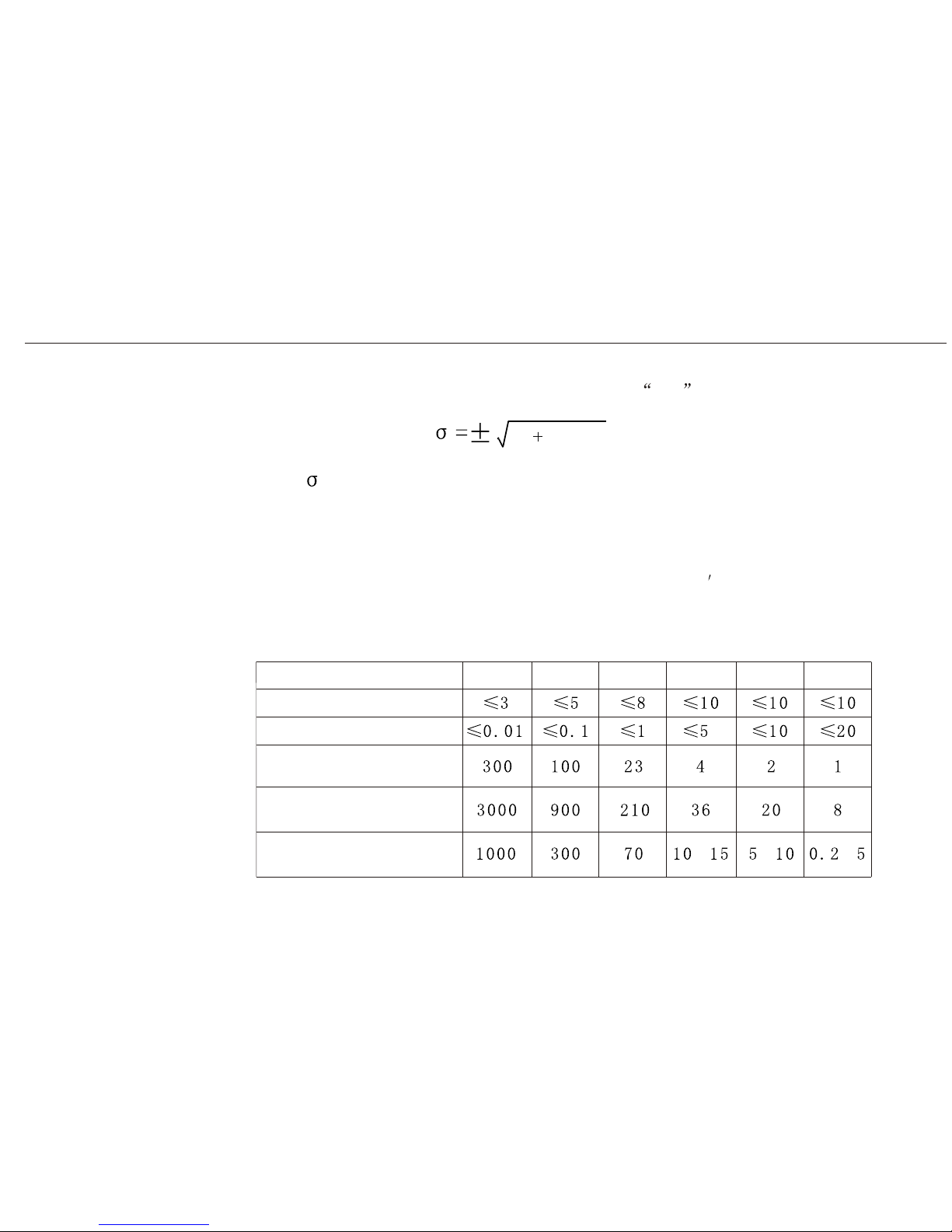
6.4.2 Accuracy Standard in Static Surveying
Accuracy standard in static surveying is judged by the rms of distance in the adjacent
two points.
22
)*( dba +
: rms (mm)
a
b
d
: fixed error (mm)
: scale factor (ppm) : distance (km)
The surveying accuracy for GPS is divided into 6 levels by Surveying Standard for GPS
published in 2001 (AA, A, B, C, D, E). AA, A, B are for country
s GPS control surveying.
Level C is mainly in engineering surveying of big or middle cities. D and E are for control
surveying in middle or small cities
A20 User Manual
40
Minimum distance for
Maximum distance for
Average distance for
Items
AA
A
B
C
D
E
Fixed error:a (mm)
Scale factor: b(ppm)
adjacent two points (km)
adjacent two points(km)
adjacent two points(km)
~ ~~
Page 52

A20 User Manual
41
6.4.3 GPS Network
There are many kinds of GPS network designing such as tracking, alternately observation,
Tracking: Several receivers fixing at the certain points for a long time observation (such
as 1 year without stop), which is suitable for level AA control survey or perma-
Alternately observation: Several receivers fixing at the points of certain district, they also
need long time surveying (several days), after this procedure, change the receivers
to the other points of this district, then use the same surveying way. This mean can
eliminate the influence of SA. It is suitable for the GPS network survey of level A
Multi-base: While several receivers are fixing at the base points (like CORS) with long time
surveying, then we can use other rovers working in this net simultaneously. It is
suitable for level C and D survey.
Single-base: Use one receiver fixing at the base point working continuously, then use rovers
to do the surveying job around base point. These rovers do not need synchron.
As a rover fix at one point, one baseline is formed. Several rovers then can form
many baselines which have the same base point like a star. It is suitable for level
D and E survey.
Normal: This way is just the general way for customers. You just follow the manual and do not
multi-base, single-base, normal.
nent monitoring survey.
and B survey.
Page 53

A20 User Manual
42
simultaneously. This moment, one polygon is formed by these receivers. After the first
surveying time is over, move these receivers to other points doing the same surveying job
(another polygon is formed by the second time surveying) but make sure that the two
polygons should have common side. The whole GPS network is formed by these polygons.
6.4.4 Shapes of GPS Network
Depend on different applications, shapes of GPS network can be divided into several types:
Radial network, Point connecting network, Side connecting network, Polygon connecting
network and Mixed connecting network.
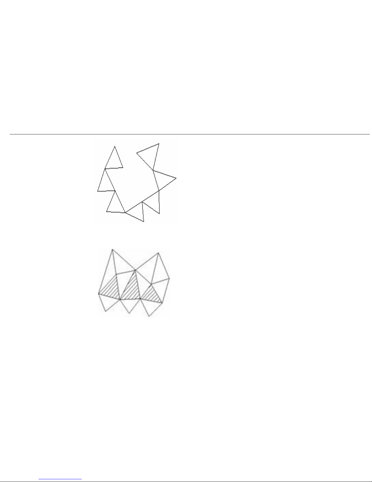
Radial network
Radial network is a simple geomatic figure, but it is not
easy to check the accuracy because all the sides of that
network are not closed. The advantages for this type is:
only need 2 receivers, which is regarded as an easy-working,
fast-tracking way. It is widely used in low precision
engineering surveying, cadastra survey, mapping and so on.
fixing on points to do the static surveying for a certain while (usually 40-60 minutes)
need to have many professional knowledge. Detailed way is, using 3 or more receivers
It is suitable for level C and D survey.
Page 54
A20 User Manual
43
Point connecting network
Point connecting network is defined as a figure by connect-
ing two adjacent shapes by only one common point. The
advantages for this type is high efficiency, fast extending,
but it also can not confirm the high precision surveying. So
it is not suggested in precise working.
Side connecting network
Side connecting network is defined as a figure by connect
ing two adjacent shapes by their common side. It is as same
as normal GPS network designing shown in the last para-
graph and is widely used in the surveying field because of
On the left is 3 receivers working simultaneously in the
Point connecting network.
its high precision.
Page 55

A20 User Manual
44
Polygon connecting network
Polygon connecting network is defined as a figure connect-
ing the two adjacent shapes by at least 3 common points.
So this network at least needs 4 receivers. It is better than side
connecting network in accuracy but not working time. So it is
only suggested for high precision control surveying.
Mixed connecting network
Because every type of network has its own disadvantage, so we can use Mixed connecting
network which can combine the advantages of these types to achieve higher efficiency
working but lower investment both in time and money.
Mixed connecting network is also the common type in doing the surveying job.
6.4.5 Principles of GPS Network Designing
Principles for GPS network designing include 3 parts, point position, reliability and
accuracy.
Page 56

A20 User Manual
45
Point position
1)Widely place is suggested because of good satellites signals, big buildings are not
allowed at the range of 10~ 15
in elevation mask.
2)Keep 200m away from high power WiFi object, e.g. radio, powerline etc.
3)It is better to be removed from the large water area, high building etc. to avoid or reduce
the effects of multipath.
4)The place for point position should be easy-going and also steady for further applications.
Reliability
1)Longer surveying time.
2)Repeated station setting is suggested.
3)Comfirm that one point should be involved at least 3 baselines.
4)The sides for every part of the network should not exceed 6.
Precision
1)Synchronous surveying is suggested in the adjacent points.
2)GPS network designing is suggested.
3)The sides for every part of network should not exceed 6.
4)High precision EDM instrument is recommended to use together with GPS receivers.
5)Leveling points should be equally spread in the district for better elevation fitting.
6)Surveying time (times) could be added appropriately for higher precision surveying.
7)Known points should be equally spread in the district for better precision surveying.
Page 57
A20 User Manual
46
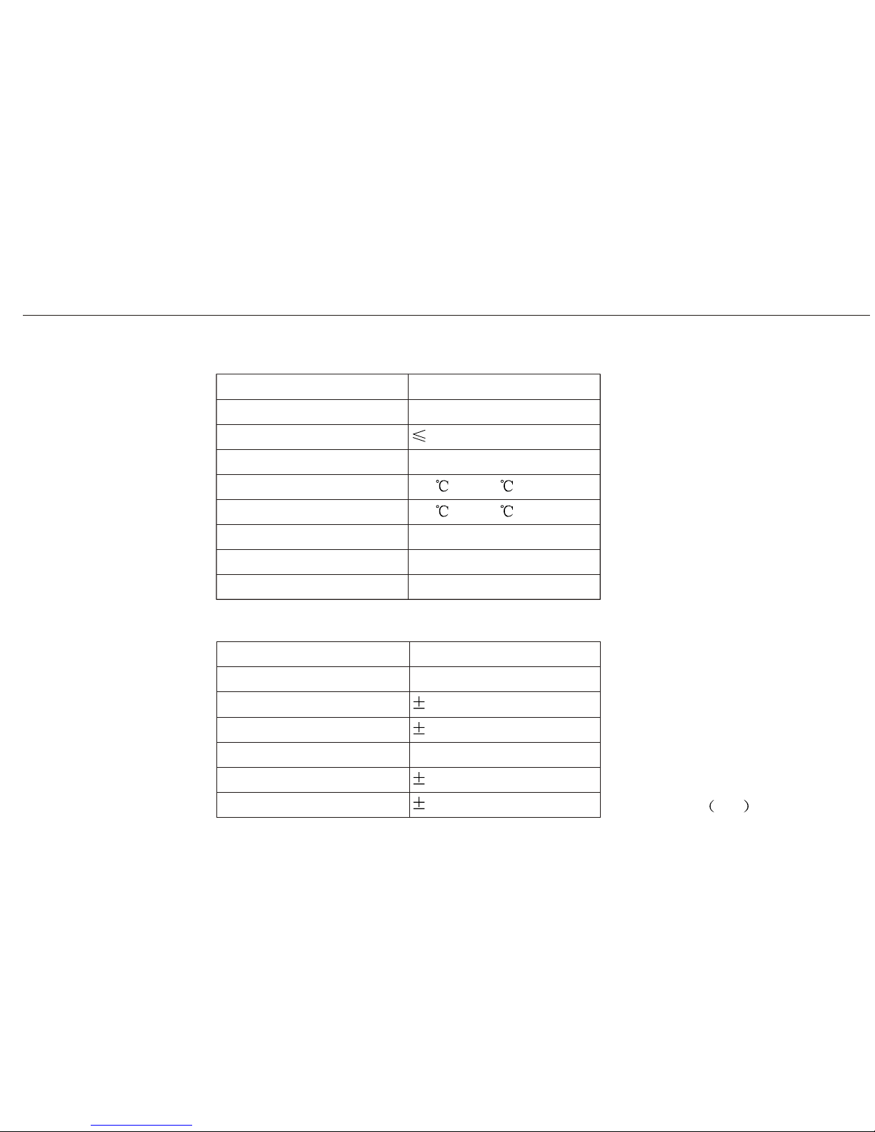
7 Specifications
7.1 Physical Specifications
Feature
Specification
Size 228*204*95mm
Weight:with battery
1.7kg
Operating time
Operating temperature
Storage temperature
Humidity
Water/Dust proof
Drops
>10 hours
-30 to +65
-40 to +75
Up to 100%
IP67,IEC529
2M pole drop
7.2 Positioning Specifications
D:distance Km
Feature
Specification
Postprocessing
Horizontal
Vertical
Real-time(RMS)
Horizontal
V ertical
2.5mm+1ppm*D
5mm+1ppm*D
10mm+1ppm*D
20mm+1ppm*D
Page 58

A20 User Manual
47
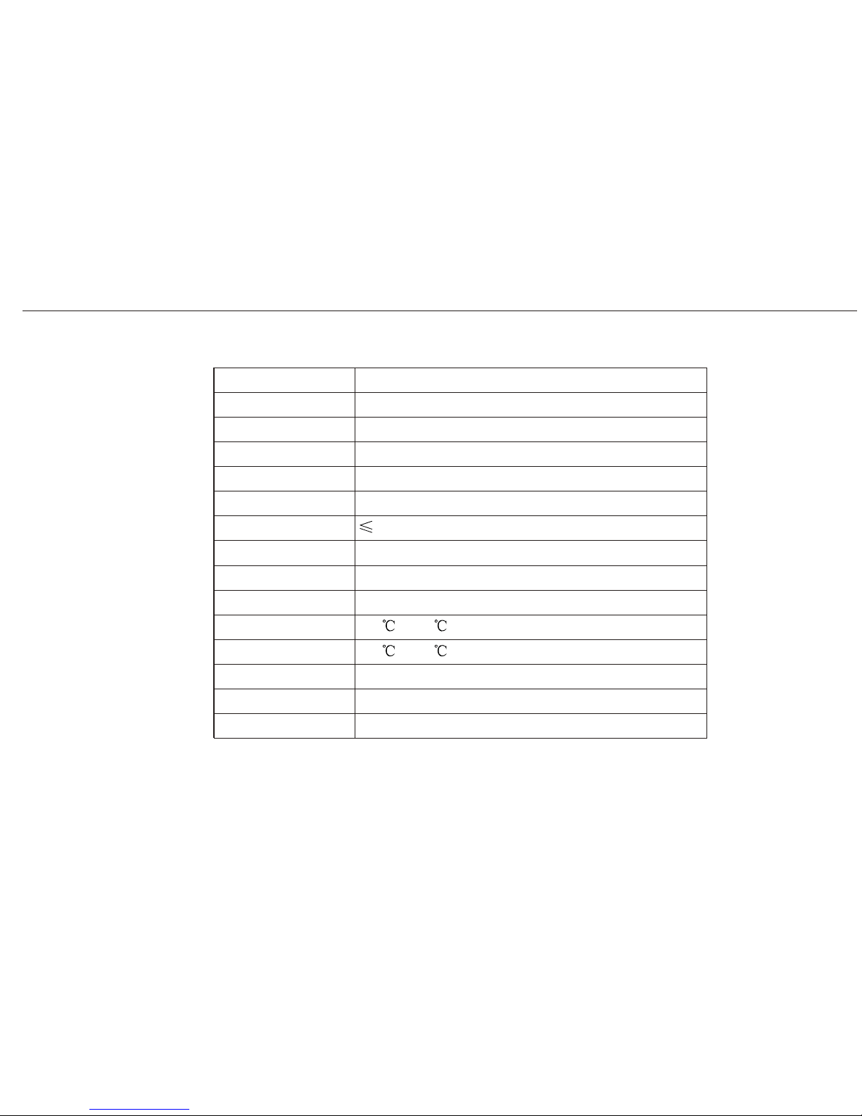
7.3 Technical Specifications
Feature
Specification
Tracking
Communication
Data formats
GPRS
Internal memory
Radio
RS232,Bluetooth
RTCM, CMR, CMR+, NMEA-0183
128MB
UHF 390MHz ~ 470MHz
54 channels, GPS 14L1,14L2,
GLONASS 12L1,12L2,2SBAS
Support GPRS
Page 59
A20 User Manual
48
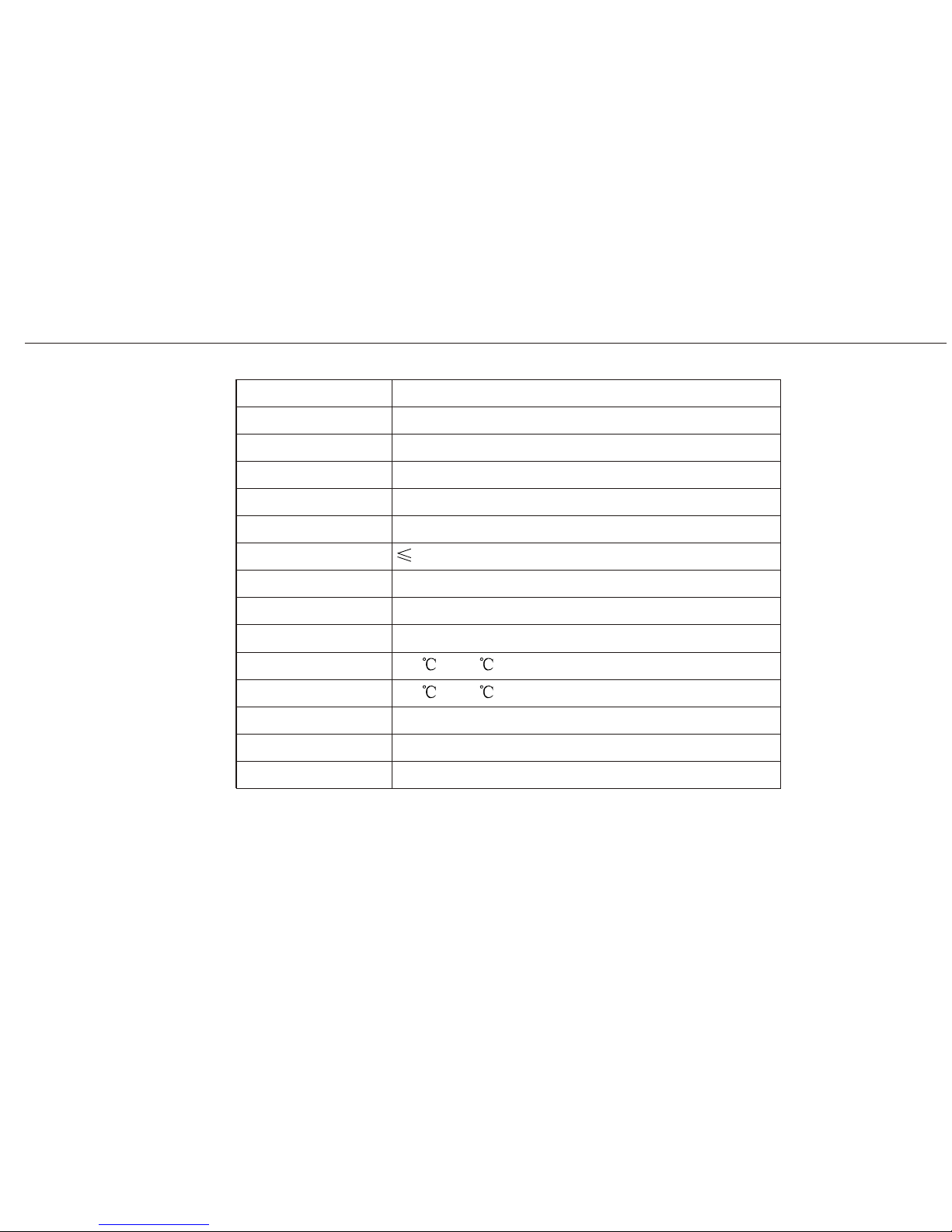
7.4 Technical Specifications for Controller
7.4.1 Getac PS236
Feature
Specification
CPU
Operation system
Communication
Working distance
I/O
Dimensions
Weight
Operating temp
Storage temp
Humidity
Water/Dust
Drops
Memory
Display
PXA310 806MHz, 32bit RISC CPU
3.5 in.VGA full colour touch screen, llumination
Microsoft Windows Mobile 6.1
128MB, extend SD card
Integrated bluetooth and RS232
10m (for bluetooth)
USB/RS232
178*89*30mm
0.5kg (Include battery)
-40 ~+70
95%
IP65, IEC529
1.52m (5ft) drops to polished concrete
-30 ~+60
Page 60
A20 User Manual
49
7.4.2 Getac PS535E (optional)
Feature
Specification
CPU
Operation system
Communication
Working distance
I/O
Dimensions
Weight
Operating temp
Storage temp
Humidity
Water/Dust
Drops
Memory
Display
Samsung2440 400MHz,CPU
3.5 in.VGA full colour touch screen, llumination
Microsoft Windows Mobile 5
2GB, extend SD card
Integrated bluetooth and USB
10m (for bluetooth)
USB
144.25*82.25*29.3mm
0.3kg (Include battery)
-30 ~+70
95%
IP54
1.52m (5ft) drops to polished concrete
-20 ~+60
Page 61

SUZHOU FOIF CO., LTD.
ADD 18 Tong Yuan Road, Suzhou 215006, P.R. China
TEL: +86 512 65224904
FAX: +86 512 65220619
Http://www.foif.com.cn
E-mail: [email protected]
 Loading...