

Page 1

SHZ-80
VP-1500
VP-2500
Order code: FOG07
Order code: FOG21
Order code: FOG22
Page 2
WARNING
FOR YOUR OWN SAFETY, PLEASE READ THIS USER MANUAL CAREFULLY
BEFORE YOUR INITIAL START-UP!
CAUTION!
Keep this equipment away from rain,
moisture and liquids.
SAFETY INSTRUCTIONS
Every person involved with the installation, operation & maintenance of this
equipment should:
- Be competent
- Follow the instructions of this manual
CAUTION! TAKE CARE USING THIS EQUIPMENT!
HIGH VOLTAGE-RISK OF ELECTRIC SHOCK!!
Before your initial start-up, please make sure that there is no damage caused
during transportation. Should there be any, consult your dealer and do not use
the equipment.
To maintain the equipment in good working condition and to ensure safe operation, it is necessary
for the user to follow the safety instructions and warning notes written in this manual.
Please note that damages caused by user modications to this equipment are not
subject to warranty.
Page 3
IMPORTANT:
The manufacturer will not accept liability for any resulting damages caused by the
non-observance of this manual or any unauthorised modication to the equipment.
• Never let the power-cable come into contact with other cables. Handle the power-cable
and all mains voltage connections with particular caution!
• Never remove warning or informative labels from the equipment.
• Do not open the equipment and do not modify the equipment.
• Only use the equipment indoors.
• Do not expose to ammable sources or gases.
• Always disconnect the power from the mains when equipment is not in use or before
cleaning! Only handle the power-cable by the plug. Never pull out the plug by pulling the
power-cable.
• Make sure that the available voltage is between 220v/240v.
• Make sure that the power-cable is never crimped or damaged. Check the equipment and
the power-cable periodically.
• If the equipment is dropped or damaged, disconnect the mains power supply immediately.
Have a qualied engineer inspect the equipment before operating again.
• If the equipment has been exposed to drastic temperature uctuation (e.g. after
transportation), do not switch it on immediately. The arising condensation might damage
the equipment. Leave the equipment switched off until it has reached room temperature.
• If your product fails to function correctly, discontinue use immediately. Pack the unit
securely (preferably in the original packing material), and return it to your Prolight dealer
for service.
• Only use fuses of same type and rating.
• Repairs, servicing and power connection must only be carried out by a qualied
technician. THIS UNIT CONTAINS NO USER SERVICEABLE PARTS.
• WARRANTY: One year from date of purchase.
OPERATING DETERMINATIONS
If this equipment is operated in any other way, than those described in this manual,
the product may suffer damage and the warranty becomes void.
Incorrect operation may lead to danger e.g. short-circuit, burns, electric shocks etc.
Do not endanger your own safety and the safety of others!
Incorrect installation or use can cause serious damage to people and property.
Before lling the unit disconnect the mains. Never ll with hot liquids.
Only use high quality, water based smoke uid recommended by the manufacturer. Other smoke uids
may cause clogging and void the warranty.
Always make sure there is sufcient smoke uid in the tank. Operating this smoke machine without
smoke uid will cause damage to the pump as well as over heating of the heater.
Operate the unit only after you have familiarized yourself with its functions, Do not permit operation by
persons not qualied for operating the unit and always drain the tank and use the original packaging if the
unit is to be transported.
Page 4
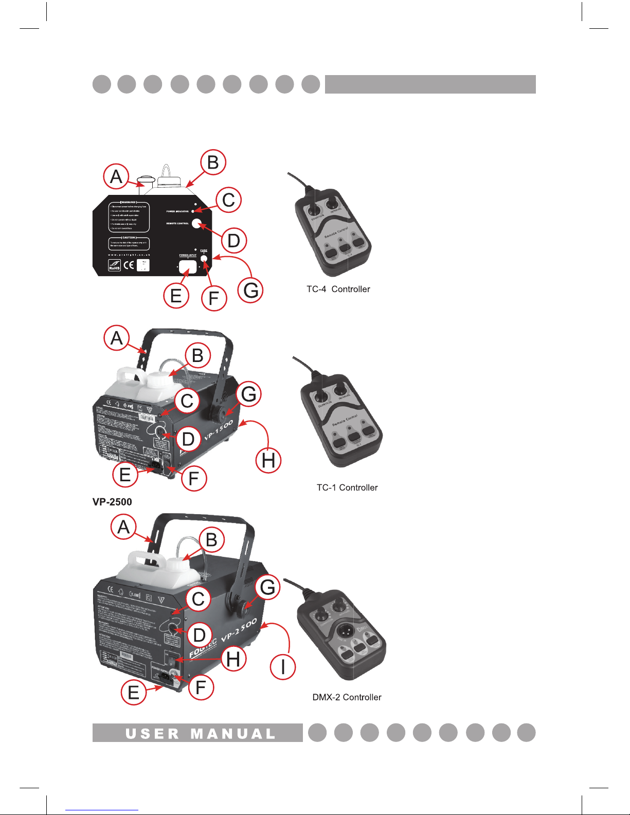
Fog machines:
SHZ-80
VP-1500
VP-2500
VP-2500
Identi cation:
A, Handle
B, Fog uid container
C, Indicator lamp
D, Remote socket
E, IEC power socket
F, Fuse
G, Low uid indicator (front)
Identi cation:
A, Bracket
B, Fog uid container
C, Indicator lamp
D, Remote socket
E, IEC power socket
F, Fuse
G, Bracket knob
H, Power switch
I, Low uid indicator (front)
Identi cation:
A, Bracket
B, Fog uid container
C, Indicator lamp
D, Remote socket
E, IEC power socket
F, Fuse
G, Bracket knob
H, Low uid indicator (front)
O V E R V I E W
Page 5
STARTING OPERATION
The uid tank of the unit needs to be lled with smoke/haze uid before switching on.
Always disconnect it from the mains supply as uid could be spilled.
Only use quality smoke/haze uids recommended by your dealer. We recommend high quality
smoke/haze uids. You must not use substances which are classied as
“DANGEROUS WORKING MATERIALS” or “FLAMMABLE FLUIDS”.
If uid should get inside the main housing, disconnect the unit from the mains immediately and
consult a technician.
INSTALLATION
Install the unit in a well-ventilated area. Use in an insufciently ventilated room can lead to the
condensation of the smoke uid. The resulting slippery surface can cause accidents. Keep a
minimum distance of 20cm around the unit.
Furthermore do not orientate the output nozzle directly in the direction of the audience’s eyes. In
order to create the best effect, there should be a distance between the unit and the audience of at
least 1.5M.
Only install the smoke machine on re resistant, scratch resistant and water resistant surfaces.
Please make sure that the installation angle does not exceed 15˚.
This unit is constructed for a free standing or hanging installation. If the unit is to be installed
overhead, please follow the safety instructions below:
RIGGING INSTALLATION
The installation has to be built and constructed in a way that it can hold 10 times the weight of the
unit(s) to be installed for 1 hour without any deformation.
The unit must always be secured with a secondary safety attachment, e.g. an appropriate catch
net or safety wire. The secondary safety attachment must be constructed in a way that no part of
the installed unit can fall down if the main attachment fails.
When rigging, derigging or servicing, do not allow personnel to be directly underneath the unit.
DANGER OF FIRE!
When installing the unit, make sure there is no highly ammable
material (decoration articles etc) within a minimum distance of 0.5M
O P E R AT I O N
Page 6
The operator must always make sure that the safety-relating and machine-technical installations
are approved by an expert before operation for the rst time and after any further changes
are made.
The operator has to make sure that the safety-relating and machine-technical installations are
approved by an expert after every four years in the form of an acceptance test.
The operator has to make sure that the safety-relating and machine-technical installations are
approved by a qualied person once a year.
PROCEDURE:
When hanging, the unit must not be installed in areas where persons may walk by or be seated.
IMPORTANT! OVERHEAD RIGGING REQUIRES EXTENSIVE EXPERIENCE, including (but not
limited to) calculating working load limits, installation materials being used, and periodic safety
inspection of all installation materials and the unit. If you are not qualied, do not attempt the
installation yourself, but instead use a professional structural rigger. Improper installation can
result in bodily injury and or damage to property.
The unit has to be installed out of the reach of people.
CAUTION: Units in overhead installations may cause severe injuries when falling! If you have
doubts concerning the safety of a possible installation, do not install the unit.
Mount the unit with the bracket to your hanging system using an appropriate clamp or bolt.
For overhead use, always install a safety wire which can hold at least 12 times the weight of the
unit. You must only use safety wires with link screw caps.
The maximum drop distance must never exceed 20cm.
A safety wire which has already held the strain of a fallen item or which is defective must not be
used again.
Adjust the desired installation angle via the mounting bracket and tighten the screws.
DANGER TO LIFE!
Before operation for the rst time, the
installation has to be approved by an expert!
R I G G I N G
Page 7
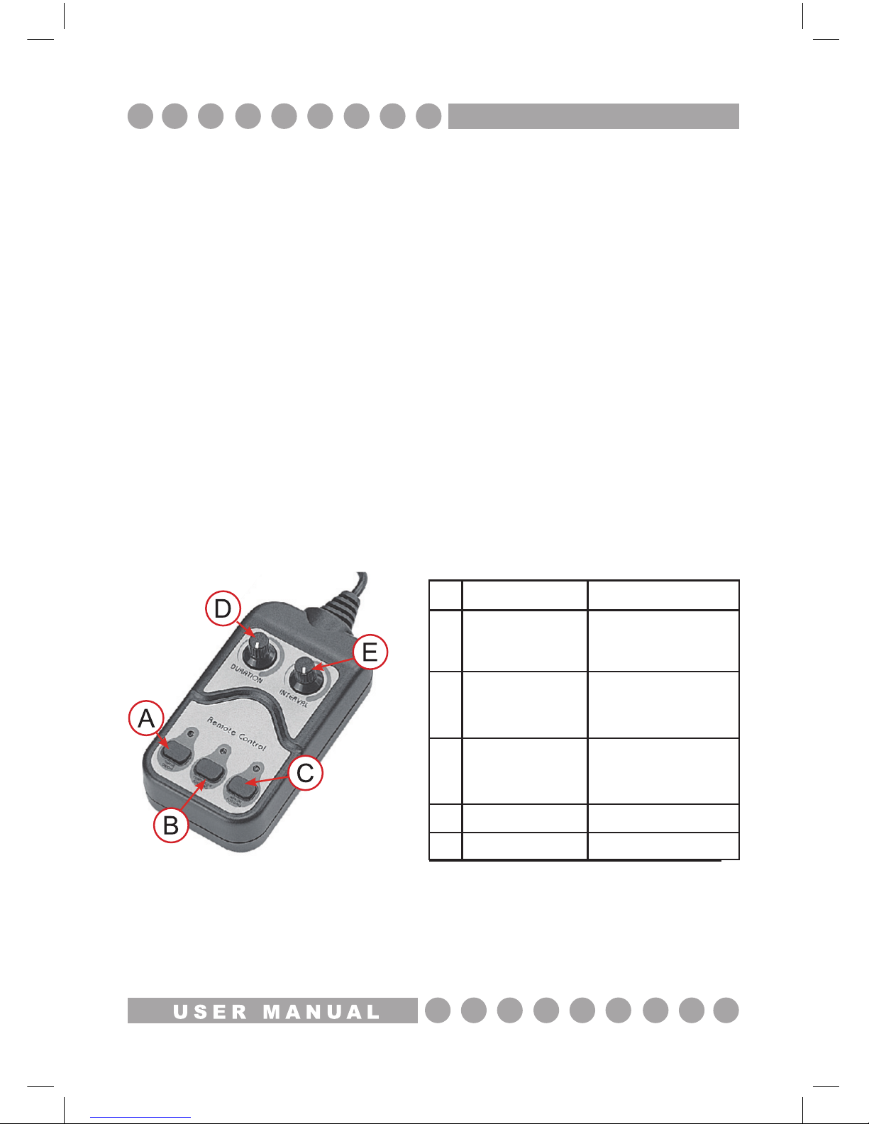
TC-1/TC-4 Controller
The TC-1 is suitable for the VP-1500 and the TC-4 is suitable for the SHZ-80 The operation is
as follows:
1, When the “MANUAL FOGGING” Green LED is OFF, this means that the fog/haze machine is
heating up. When the Green LED illuminates, the fog/haze machine has heated up and is ready
for use.
2, When the “TIMERS” and “CONTINUOUS” buttons are pressed OFF; the fogging duration
can be adjusted by turning the “DURATION” knob.
The “INTERVAL” knob will adjust the amount of time in between every fog output.
3, When the “CONTINUOUS” button is pressed ON, the Red LED will light illuminate, the
machine will now emit fog continuously until the Green LED goes OFF (indicating the fogger/
hazer is heating up again) , The “TIMERS” and “MANUAL” buttons are ineffective in this mode.
4, When the “TIMERS” button is pressed ON and the “CONTINUOUS” button is pressed OFF,
the machine can be controlled manually by pressing the “MANUAL” button.
Note: Before removing or replacing the remote control unit, disconnect the power cable.
TC-1 - TC-4 Controller
Function Instruction
Timers On/Off
Continuous
Fogging
Manual
Fogging
Duration
Interval
Press this button and
the timer of the interval
output will stop and the
red LED will illuminate.
Press this button and the
fog machine will emit fog
continuously and the
red LED will illuminate.
Press this button and it allows
the operation to be controlled
manually.
0.5s ~ 10s +/- 1s
9s ~ 280s +/- 20s
A
B
C
D
E
C O N T R O L L E R S
Page 8
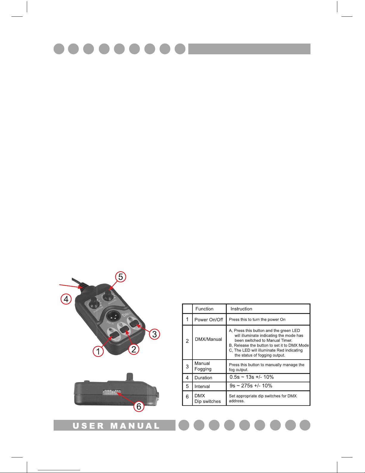
DMX-2 controller appendix
The DMX-2 is suitable for the VP-2500, the operations are as follows:
1, When the “MANUAL FOGGING” Green LED is OFF, this means that the fog/haze machine is
heating up. When the Green LED illuminates, the fog/haze machine has heated up and is ready
for use.
2, When the “POWER ON/OFF” button is pressed (no LED illuminated) the machine will emit fog
continuously until the Green “MANUAL FOGGING” LED goes off, indicating the machine is
heating up again..
3, When the “DMX/MANUAL” button is pressed ON the green LED will light up, now you can
control fogging manually. The “DURATION” control knob is used to adjust the length time the fog
is emitted while the “INTERVAL” control knob is used to decide the mean time between
outputting the fog.
Note: The functions of the Duration and Interval only work under the Manual Timer mode.
6, When the “DMX/MANUAL” button is pressed OFF, the timer function is now controlled via the
DMX output. The DMX-2 has two channels:
Channel 1: To adjust the duration
Channel 2: To adjust the Interval
For setting the DMX address please refer to the DMX chart overleaf.
7, The LED above the “DMX/MANUAL” button has a dual colour LED (red and green).
When it is illuminated Green this indicates the operation mode of the button.
When it is Red this indicated the status of fogging
NOTE: Manual Fogging mode overrides DMX Mode.
C O N T R O L L E R S
Page 9
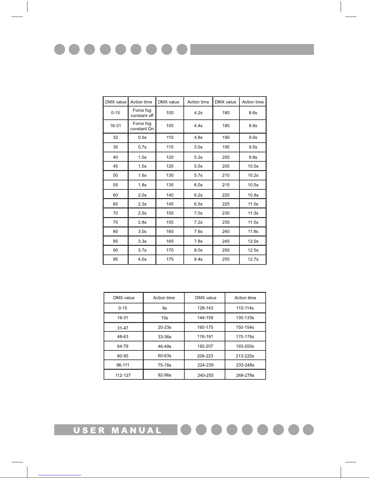
DMX Charts
CH 1: Duration (time deviation: 10%)
CH 2: Interval (Time deviation: 10%)
D M X C H A R T S
Page 10
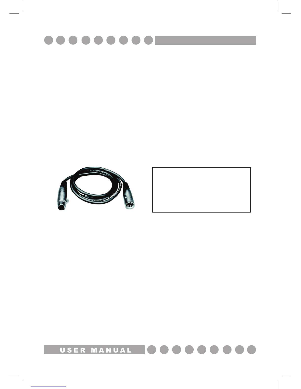
DMX-512:
• DMX (Digital Multiplex) is a universal protocol used as a form of communication between
intelligent xtures and controllers. A DMX controller sends DMX data instructions form the
controller to the xture. DMX data is sent as serial data that travels from xture to xture via the DATA
“IN” and DATA “OUT” XLR terminals located on all DMX xtures (most controllers only have a data “out”
terminal).
DATA Cable (DMX cable) requirements (for DMX operation):
• The Fogtec VP-2500 can be controlled via DMX-512 protocol. The DMX address is set on the back of
the unit. Your unit and your DMX controller require a standard 3-pin XLR connector for data input/output
(gure 1).
Figure 1
Also remember that DMX cable must be daisy chained and cannot be split.
Further DMX cables can be purchased from
all good sound and lighting suppliers or
Prolight dealers.
Please quote:
CABL10 – 2M
CABL11 – 5M
CABL12 – 10M
D M X S E T U P
Page 11
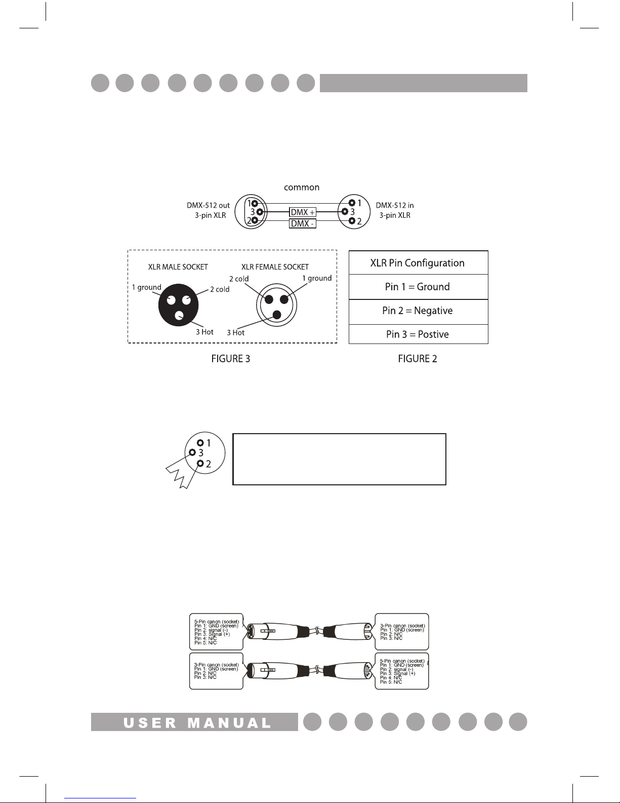
Notice:
• Be sure to follow gures 2 & 3 when making your own cables. Do not connect the cable’s shield
conductor to the ground lug or allow the shield conductor to come in contact with the XLR’s outer casing.
Grounding the shield could cause a short circuit and erratic behaviour.
Special Note: Line termination:
• When longer runs of cable are used, you may need to use a terminator on the last unit to
avoid erratic behaviour.
Using a cable terminator (part number CABL90) will decrease the possibilities of
erratic behaviour.
5-Pin XLR DMX Connectors:
• Some manufactures use 5-Pin XLR connectors for data transmission in place of 3-pin. 5-Pin
XLR xtures may be implemented in a 3-pin XLR DMX line. When inserting standard 5-Pin
XLR connectors in to a 3-pin line a cable adaptor must be used. The Chart below details the
correct cable conversion.
Termination reduces signal transmission problems
and interferance. it is always advisable to connect a
DMX terminal, (resistance 120 Ohm 1/4 W) between
pin 2 (DMX-) and pin 3 (DMX+) of the last fixture.
D M X S E T U P
Page 12
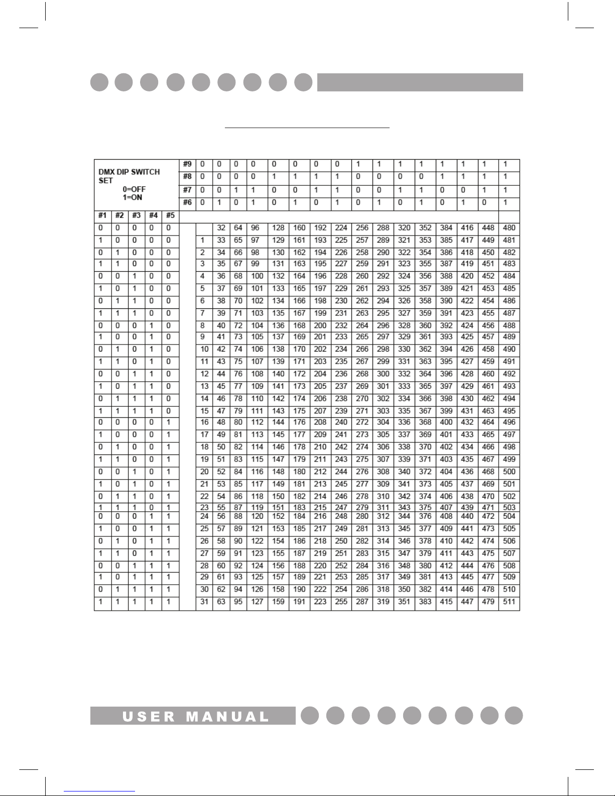
DMX Dip Switch Quick Reference Chart
Dip Switch Position
D I P S W I T C H C H A R T
Page 13
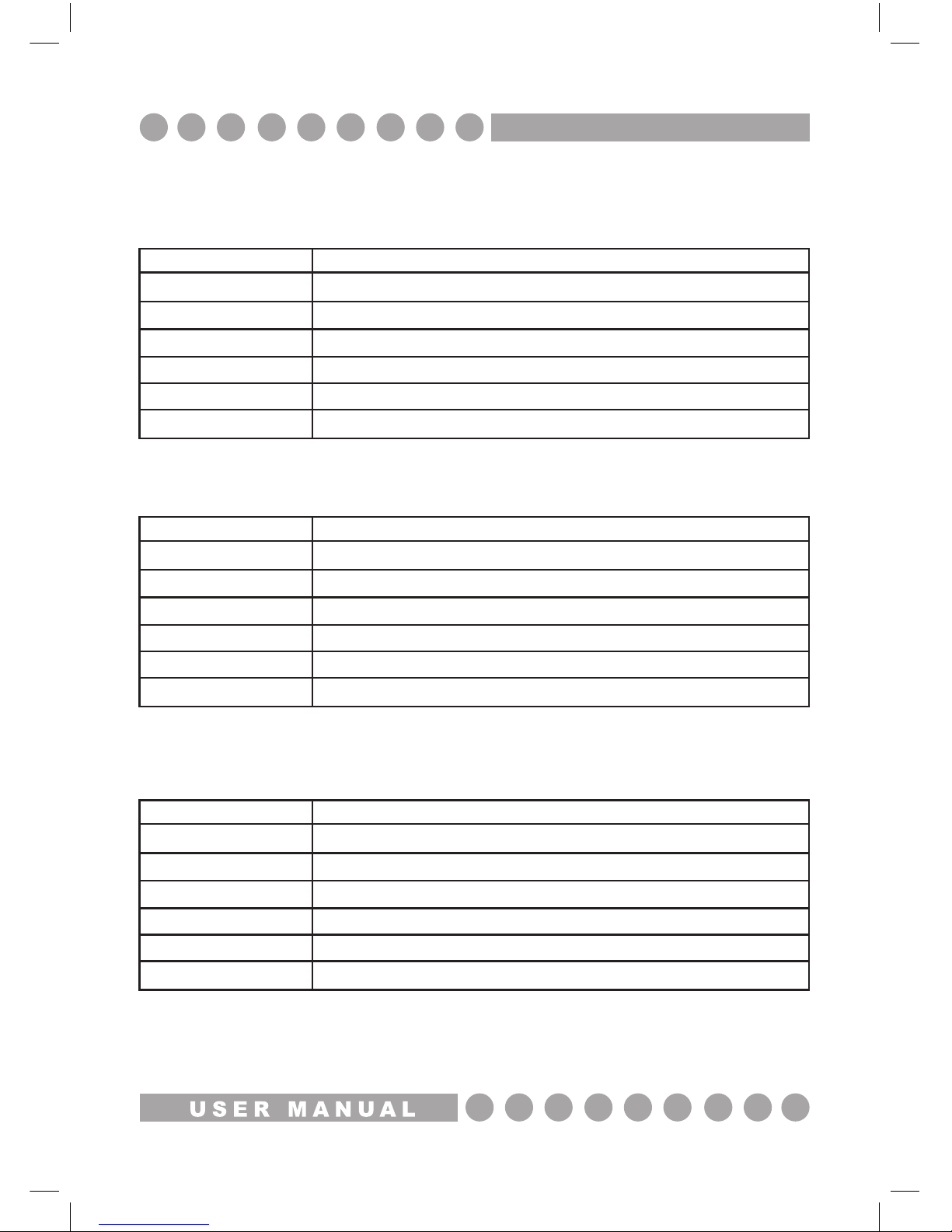
TECHNICAL SPECIFICATIONS
SHZ-80
VP-1500
VP-2500
Smoke output
Warm up time
Tank capacity
Power consumption
Power supply
Dimensions
Weight
1.500 cu.ft per minute
approx. 4 min
2 L
800W
240V
526 x 207 x 173mm
7.6Kgs
Smoke output
Warm up time
Tank capacity
Power consumption
Power supply
Dimensions
Weight
14,000 cu.ft per minute
approx. 8 min
2.5 L
1500W
240V
300 x 220 x 160mm
6.1Kgs
Smoke output
Warm up time
Tank capacity
Power consumption
Power supply
Dimensions
Weight
21,000 cu.ft per minute
approx. 8 min
5 L
2500W
240V
435 x 280 x 290mm
10.5Kgs
S P E C I F I C AT I O N S
Page 14

Page 15

Page 16

w w w . p r o l i g h t . c o . u k
 Loading...