

Page 1
English
E 167 GB
ISSUE 6 : 02/2003
QUADRA
493 9021
493 9023
493 9031
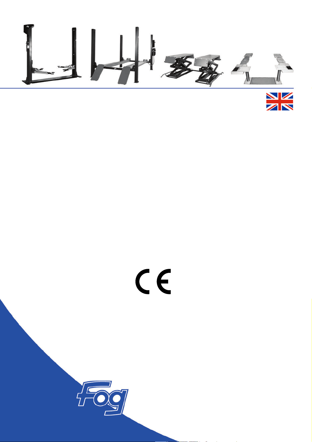
VEHICLE LIFT
4 COLUMNS 3,5 TONNE
(AUXILIARY LIFT 3 TONNE)
Installation
Operation
Maintenance
Page 2

493 9021
493 9031
QUADRA
CONTENTS
HEALTH AND SAFETY PRECAUTIONS ............................................................................................................... 3
WARNINGS, CAUTIONS AND NOTES ............................................................................................................. 3
INSTALLATION ................................................................................................................................................ 6
Location and layout, Floor Specification
ASSEMBLING THE SUPERSTRUCTURE ............................................................................................................... 8
Identification of main components
Preparing the cross member
Component position
Platform level adjustment
Column adjustment
Motor column assembly
Fitting the wire ropes
Fitting the ladder racks
Fitting the hydraulic hose and electrical connections
CONNECTING TO THE ELECTRICITY SUPPLY .................................................................................................. 15
COMMISSIONING THE PUMP ....................................................................................................................... 15
Fitting accessories
Adjusting the level of the platform
Adjusting the wire ropes
Fitting and adjusting the Tie rods
Checking the column adjustment
Checking the latches
Checking the rocker arm retaining system
Checking the safety brake cam
Checking the wire rope safety switches
Checking the adjustment of the wire rope safety switches
Checking the obstruction/wire rope failure sensor
Checking the ladder latching
Checking the ram safety valve
COMMISSIONING THE AUXILIARY LIFT .......................................................................................................... 21
OPERATION .................................................................................................................................................. 22
Positioning the vehicle, Raising the platform, Lowering the platform
RAISING & LOWERING THE AUXILIARY PLATFORMS (493 9031) ...................................................................... 23
“LOWER” CONTROL...................................................................................................................................... 23
Changing the position of the lever
RAM SAFETY VALVE ....................................................................................................................................... 24
Check and adjustments, Thread torque
LOWER THE PLATFORM AND AUXILIARY WITHOUT ELECTRICAL POWER ......................................................... 24
MAINTENANCE ............................................................................................................................................ 26
General, Monthly, Annual lift test
OVERLOAD TESTS .......................................................................................................................................... 27
FAULT FINDING ............................................................................................................................................ 28
TECHNICAL SPECIFICATION .......................................................................................................................... 36
ADD-ON FOR 493 9021 ................................................................................................................................. 37
ADD-ON FOR 493 9031 ................................................................................................................................. 44
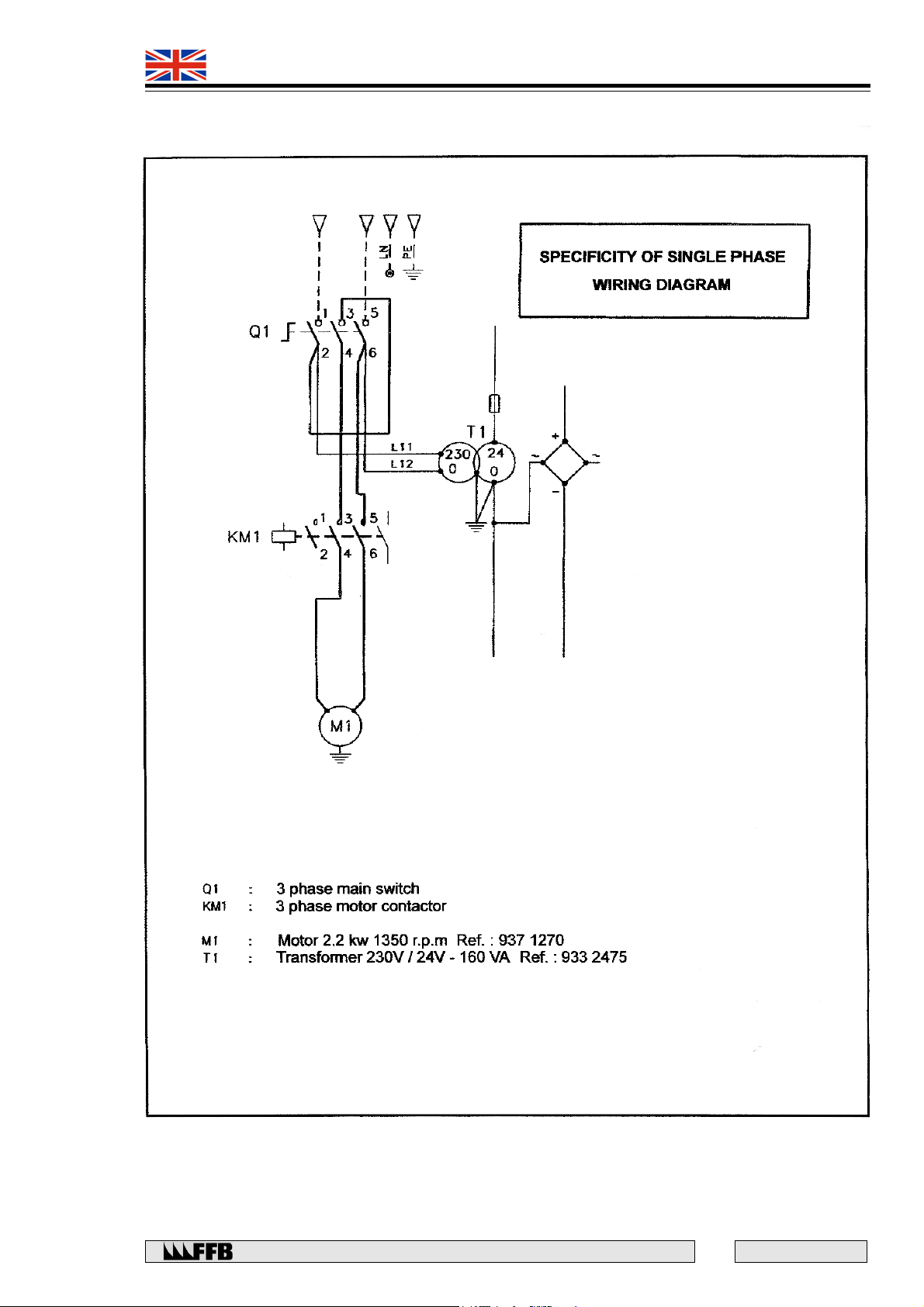
SPECIFICITY OF SINGLE PHASE WIRING DIAGRAM ........................................................................................ 55
PROCEDURE ADJUSTMENT OF THE FLOW CONTROL VALVE (POWER UNIT HPI) ............................................... 56
WARRANTY RETURN FORM .......................................................................................................... 57
DECLARATION OF CONFORMITY .................................................................................................................. 59
E 167 - GB - 6
2
Rue du Pré Neuf - 58440 MYENNES FRANCE
Page 3
493 9021
493 9031
QUADRA
I HEALTH AND SAFETY PRECAUTIONS
In order to comply with your responsibilities under the Health and Safety at Work Act 1974, it is essential
that the Quadra and any optional accessories are sited, installed, operated, and maintained by *competent
persons in accordance with the instructions in this manual.
* A competent person should be a minimum of 18 years of age and have a minimum
qualification of NVQ 3 (or an equivalent qualification) and / or experience within their
own field of responsibility, e.g. installation engineering, automobile engineering etc.
It is important that all persons installing, operating or maintaining the Quadra and
optional accessories must also be familiar with the layout of the equipment, safety
precautions and vehicle lifting points. Appropriate training will be required,
prior
to
installing, using or maintaining the lift
WARNINGS, CAUTIONS AND NOTES
‘WARNING’ is used in the text of this manual to identify specific hazards which can cause injury or death.
‘CAUTION’ is used in the text of this manual to identify incorrect procedures which can cause damage to the
Quadra.
‘NOTE’ is used in the text of this manual to draw attention to specific points of importance.
WARNING SYMBOLS
WARNING
READ THIS
MANUAL
BEFORE USE
ELECTRICAL
DANGER
230V OR 400V
WARNING
OR
CAUTION
Rue du Pré Neuf - 58440 MYENNES FRANCE
3
E 167 - GB - 6
Page 4

493 9021
493 9031
QUADRA
E 167 - GB - 6
CE IDENTIFICATION PLATE
4
Rue du Pré Neuf - 58440 MYENNES FRANCE
Page 5

493 9021
493 9031
Changes to this manual are as shown below. Revised or additional issues of this manual are available
from F.F.B. S.A. Rue du Pré Neuf 58440 MYENNES - FRANCE.
Minor changes are indicated by the use of a broad line adjacent to the affected text.
PUBLICATION ISSUE CHANGES TEXT AFFECTED
26/08/97 Artwork Layout
05/99 2 euro
12/01 3 Modifications of the references in all the doc.
05/02 4 Specificity of single phase wiring diagram and Procedure
07/02 5 Suppression of the paragraph “Checking the upper limit
QUADRA
493 9001 --> 493 9021; 493 9003 --> 493 9023
493 9011 --> 493 9031 + insertion of additives 493 9021
& 493 9031.
adjustment of the flow control valve added, CE identification
plate updated, modifications of Fig. 7 p.17, Fig. 19 p.27,
Fig. 19, 20 and 21 p.37, and suppression of the paragraph
“Re-fitting the lever” p. 42 and of the Fig. 20 p. 43.
switch” p. 34, some modifications p. 36 and more precise
wiring diagram p. 2 of the additive 493 9031.
02/03 6 Warranty return form now included and EC declaration of
conformity updated.
MODEL NO:
SERIAL NO:
DATE OF INSTALLATION: .............................................
DATE OF LOAD TESTS: .............................................
INSTALLED BY: .............................................
Rue du Pré Neuf - 58440 MYENNES FRANCE
5
E 167 - GB - 6
Page 6
493 9021
493 9031
QUADRA
INSTALLATION
Location and site layout
This lift should be installed so that:
• It is sheltered from the elements.
• There is sufficient headroom.
• The “motor column” that houses the power-pack, control box etc. is positioned at the rear
on the left-hand side.
• A three-phase power supply is available nearby (400 V, 1.85 kW). This must have fused
circuit protection. NOTE: With 400 V, a neutral conductor is not required to operate the
lift, but it will allow any accessories requiring a 230 V supply e.g. lighting to be fitted.
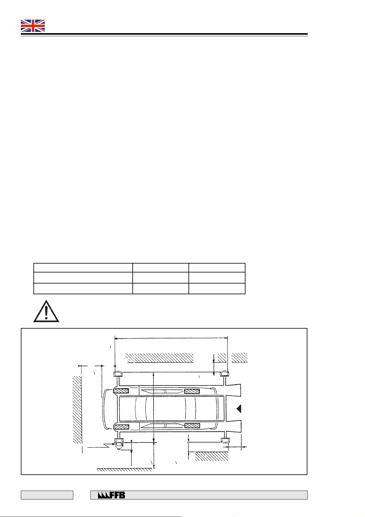
• The front or rear of the vehicle must not come into contact with walls, doors or any
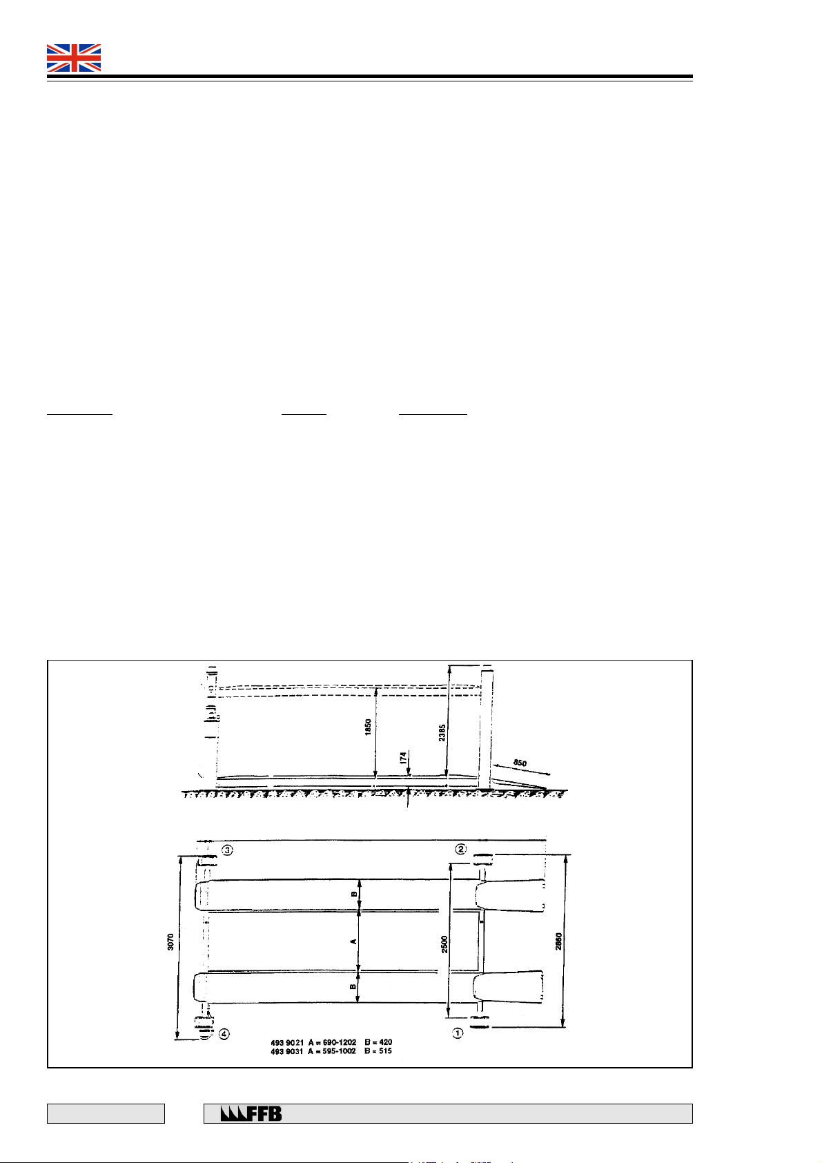
other obstructions, and all minimum safety clearances must be observed (Fig. 1).
Floor Specification
With regard to the area on which the four column base plates are to be positioned :
• The floor must be on a common horizontal plane (within +/- 4mm) including that up to
2000mm in front of the cross-member(s) so that vehicles with restricted ground clearance
can drive onto the platform. A slight downward slope towards the front of the lift is
acceptable, provided that it is compensated for by placing shims under the columns.
• The pads must be constructed from C:30 concrete extending over a minimum area of
800 x 650 mm and at least 160mm thick, excluding the thickness of any screed or paving that
may be added. In the case of an existing floor, check its suitability with qualified person
e.g. structural engineer, architect etc.
Where the lift is to be installed on an upper storey, the floor should be able to withstand the stresses given
below. This should be checked by a qualified person e.g. structural engineer, architect etc.
493 9021 493 9031
Uniformly distributed loading 242 kg/m
Point loading 1.6 kg/cm
2
2
266 kg/m
1.8 kg/cm
2
2
CAUTION: THE OVERLOAD FIGURES GIVEN ABOVE DO NOT TAKE INTO
ACCOUNT ANY DYNAMIC OR STATIC OVERLOAD TESTS OR THE PARKING
OF A VEHICLE UNDER A LOADED PLATFORM.
4430
~
( 950)
required
if access
>800
Depending on
vehicule
2784
>650 or 800
ACCESS
Fig. 1
E 167 - GB - 6
Power
supply
required
if access
> 1040
6
Rue du Pré Neuf - 58440 MYENNES FRANCE
>650 or 800
800
Page 7
493 9021
493 9031
QUADRA
Electrical supply
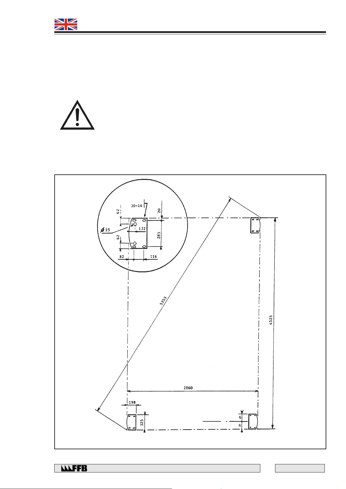
Provision may be made for a conduit in the floor (minimum 20mm internal diameter) which exits either
outside the base plate or in the column through the 25mm diameter hole (Fig. 2).
Columns
The columns are secured to the concrete pads with the anchor bolts supplied.
CAUTION: IF THE FLOOR IS SCREEDED OR TILED, THE LENGTH OF THE
ANCHOR BOLTS SHOULD BE INCREASED PROPORTIONALLY - CUSTOMER
RESPONSIBILITY.
Floor Plan
Mark clearly around the outside contour of the column base plates. (See Fig. 2)
Elongated
hole
(Theoretical)
Fig. 2
Cross-member axis
Rue du Pré Neuf - 58440 MYENNES FRANCE
7
E 167 - GB - 6
Page 8
493 9021
493 9031
QUADRA
ASSEMBLING THE SUPERSTRUCTURE
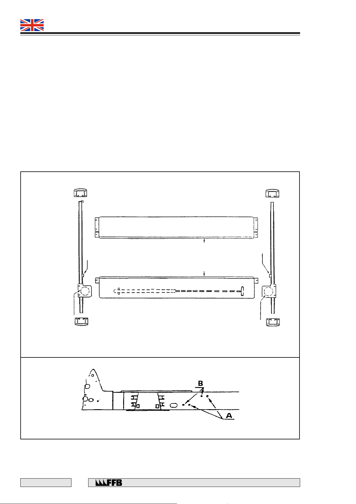
Identification of the main components
Unpack the component parts and identify them in accordance with Fig. 3.
The motor column (4) has several holes on its main face as well as the identification and instruction plates.
Columns 1, 2 and 3 are all similar, but the one that has a large vertical ‘Fog’ logo must be positioned on
the ‘drive on’ side on the left.
Preparing the cross members
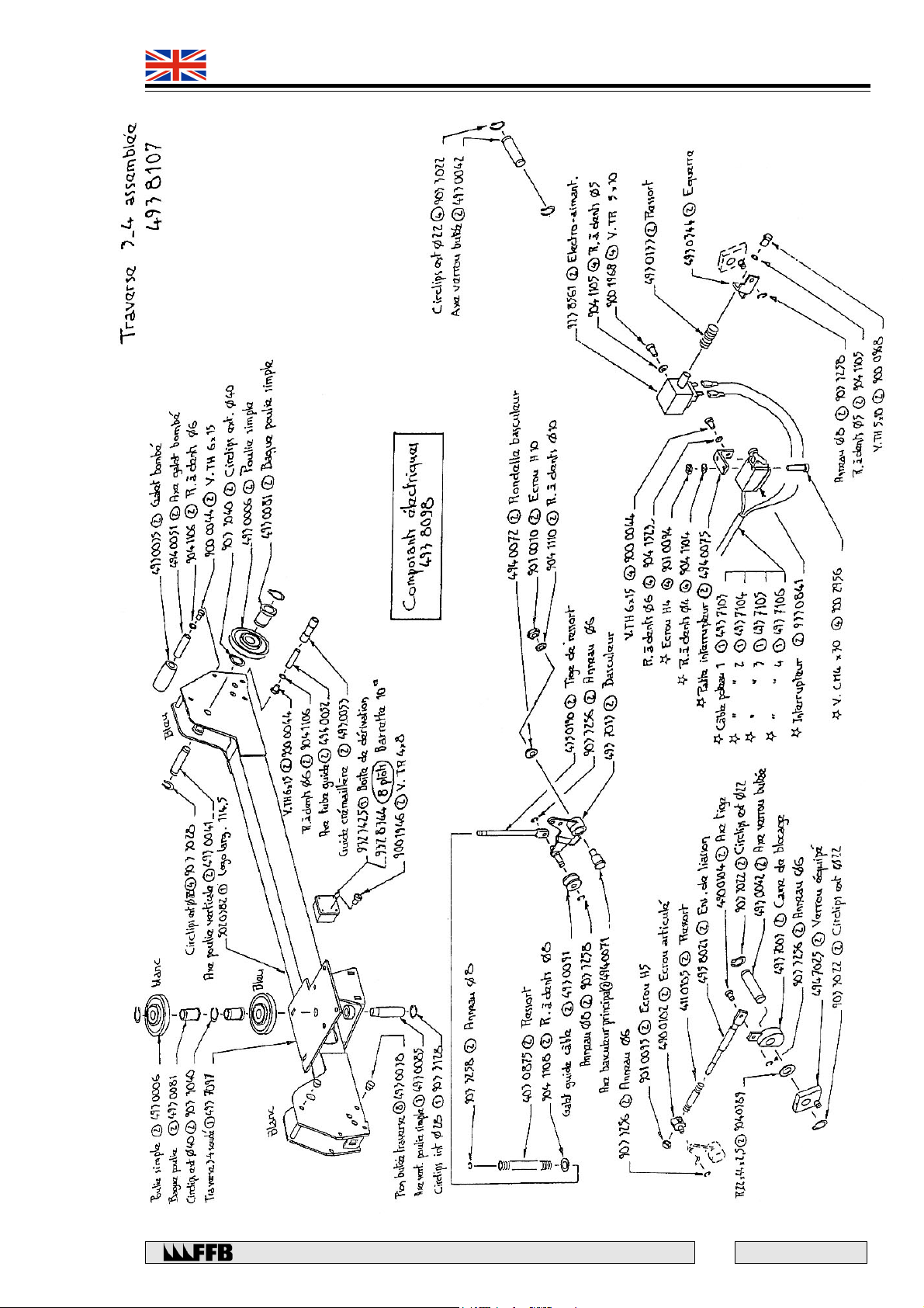
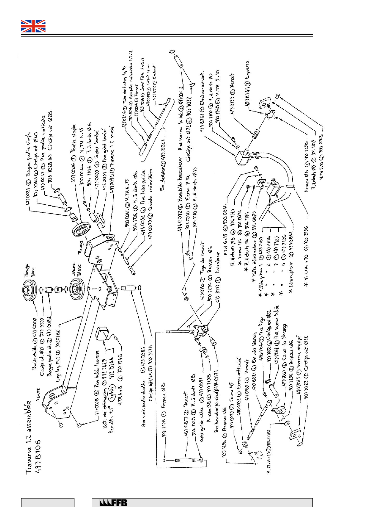
Position the junction boxes correctly according to the type of lift (see Fig.4):
• in holes (A) for lift 493 9021
• in holes (B) for lift 493 9031
Horizontal gusset
with single pulley
Fig. 3
COLUMN 3
Junction
box
CROSS-MEMBER 3 - 4
COLUMN 4
(motor)
ADJUSTABLE
TRACK
FIXED
TRACK
Wheel-guides
Horizontal gusset
with single pulley
COLUMN 2
Junction
box
CROSS-MEMBER 1 - 2
COLUMN 1
Fig. 4
E 167 - GB - 6
8
Rue du Pré Neuf - 58440 MYENNES FRANCE
Page 9

493 9021
493 9031
QUADRA
Component position
Position on the floor plan all of the components that make up the lift, in the following order:
• Cross-members: Place a suitable support under the cross-members, and under the horizontal gusset.
• Columns: Engage the columns as far as possible onto the vertical cheek-plates of the cross
members and position them correctly on the floor, move the cross-members if necessary.
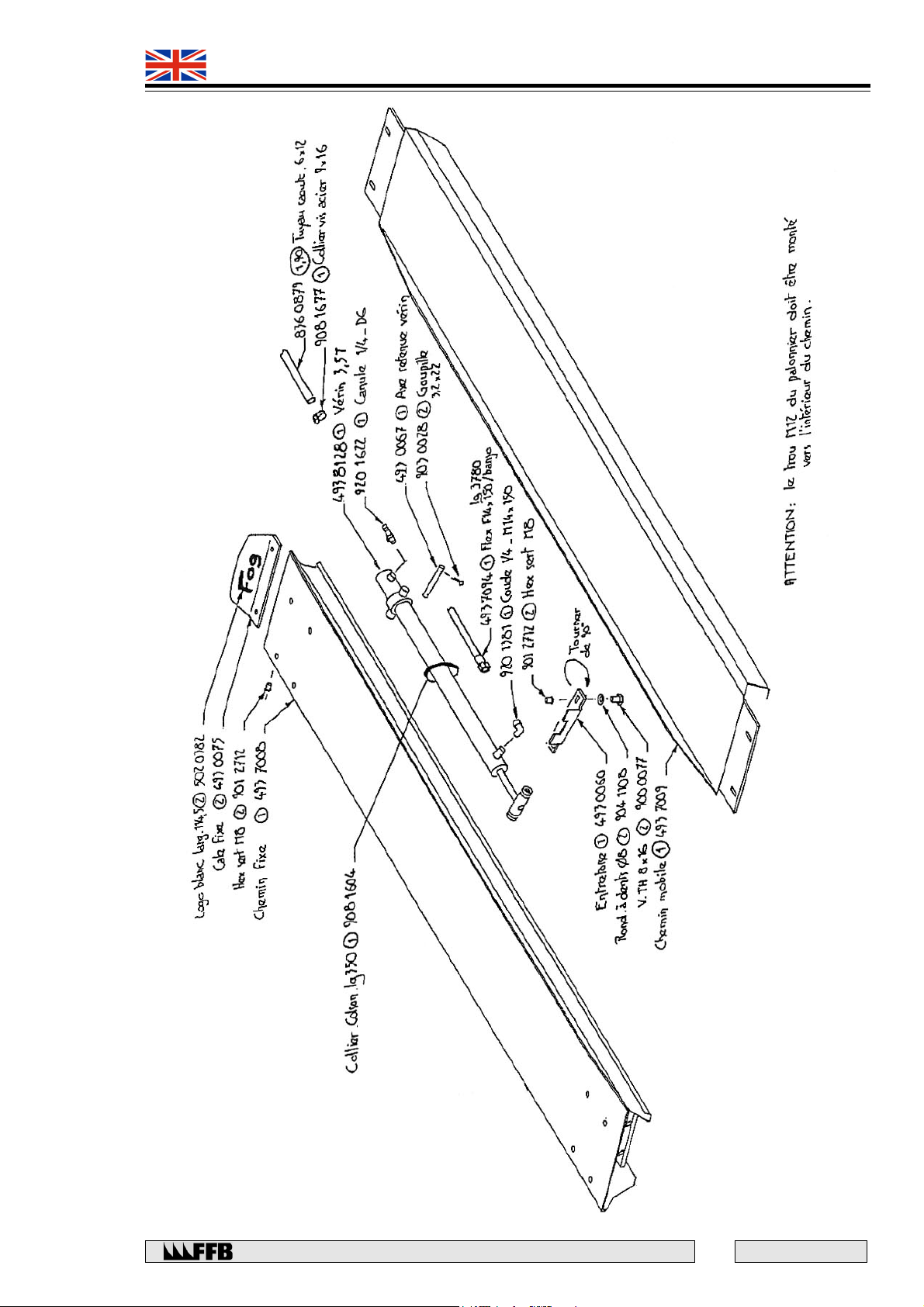
• Fixed track: Place the fixed track on the cross-member horizontal gussets, with its wheel guide
flange facing inwards. Locate the connecting screws (Fig. 5) but do not tighten them. Pay
attention to the position of the wire rope guide screws.
• Adjustable track: Place the adjustable track on the cross-members as far as possible from the
fixed track and with its wheel guide flange facing inwards. Move the ends of the crossmembers so the track can fit in-between them in order to give 2 to 3 mm clearance between
the cross-member beam and the bosses at each end (Fig. 6). Tighten the connecting screws to
secure the horizontal gusset onto the fixed track.
Platform level adjustment
Adjusting the amount of shims under the cross-members. To ensure that the platform is level. This can be
verified as follows:
• laterally, using a spirit-level on the cross-members.
• longitudinally, using a spirit-level in the centre of the track.
Column adjustment
Measure and compare the distances between the column base plates and the ends of the cross-members.
A difference of 15 mm can be accommodated by adjusting the ladder rack in the column. If the difference
is greater than this, the lowest column(s) should be raised by placing shims under the base plate(s) or by
using the lifting screws.
Maintain the position of the base plate on the floor plan, then check each column in succession as follows:
• Whether it is vertical, using a plumb-line. If not, place shims under the base plate or adjust the
lifting screws.
• Whether it is square, using a rule placed on the main inside face of the column and sighting
the column opposite.
• Whether there is clearance of 1mm between the roller on the end of the cross-member and
the inside of the column (Fig. 14).
Rue du Pré Neuf - 58440 MYENNES FRANCE
9
E 167 - GB - 6
Page 10
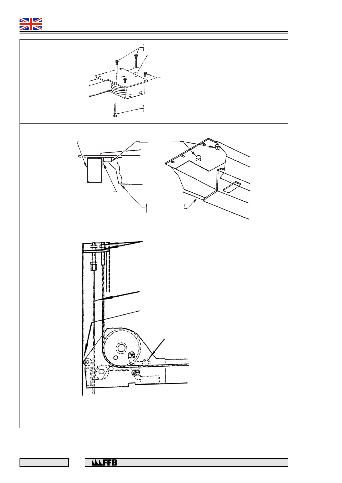
Fig. 5
493 9021
493 9031
QUADRA
TOP CABLE
GUIDE
SCREW M12 X 20
BOTTOM CABLE
GUIDE
Fig. 6
CROSS-MEMBER
Clearance: 2 to 3 mm
BOSS
ADJUSTABLE
TRACK
NUT M 20
LADDER RACK
Fig. 14
E 167 - GB - 6
10
Approx. 1 mm clearance
(only with cross-member in
bottom position)
ROLLER
Rue du Pré Neuf - 58440 MYENNES FRANCE
Page 11

493 9021
493 9031
QUADRA
Anchoring the columns
Drill the holes for the anchor bolts using the base plates as templates. Ensure that the columns are as vertical
as possible and concentric in relation to the base plate holes in order to allow column adjustment. If drilling
cannot be completed with the column in place, trace the position of the holes on the floor as accurately as
possible, remove the column and its shims, noting their positions.
Fit a large washer in position under the bolt head, locate the anchor bolts in position and tighten them.
Before anchoring the motor column, ensure all the necessary parts are fitted. Check the column adjustments
(verticality, squareness and 1mm clearance), alter the shims if necessary.
Motor column assembly
While it is more convenient to assemble the motor column when it is positioned at bench height, it is also
possible to do this with the column in an upright position, secured to the ground (See Fig. 7).
CAUTION: THE MOTOR COLUMN ASSEMBLY WILL NOT STAND UPRIGHT BY
ITSELF. THE RESERVOIR FOR THE MOTOR PUMP UNIT IS MADE OF PLASTIC.
• Attach the control panel mounting plate using four TH M8 x 16 screws and serrated lock washers.
• Attach the power-pack using four TH 8 x 16 screws and serrated lock washers between the 'U' bracket
and the column and four M8 x 20 screws, serrated lock washers and M8 nuts between the motor and
the 'U' brackets).
• Position the motor coupling links as appropriate and connect the cable, route it to the left of the motor.
• Attach the upper limit switch to its bracket using two C M4 x 25 screws and serrated lock washers.
Fit the bracket to the top of column on the inside with two TH M6 x 10 screws and serrated lock washers.
• Feed the cable through the column and connect it onto the control panel.
Fitting the wire ropes
• Bring the platform to rest on the latches at about 1000 mm from the floor, by alternately raising each
cross-member 2 or 3 slots, using a crane, jack or a lever engaged in one slot of the ladder rack and a
wooden block inserted between the lever and the bottom of the vertical cheek plate.
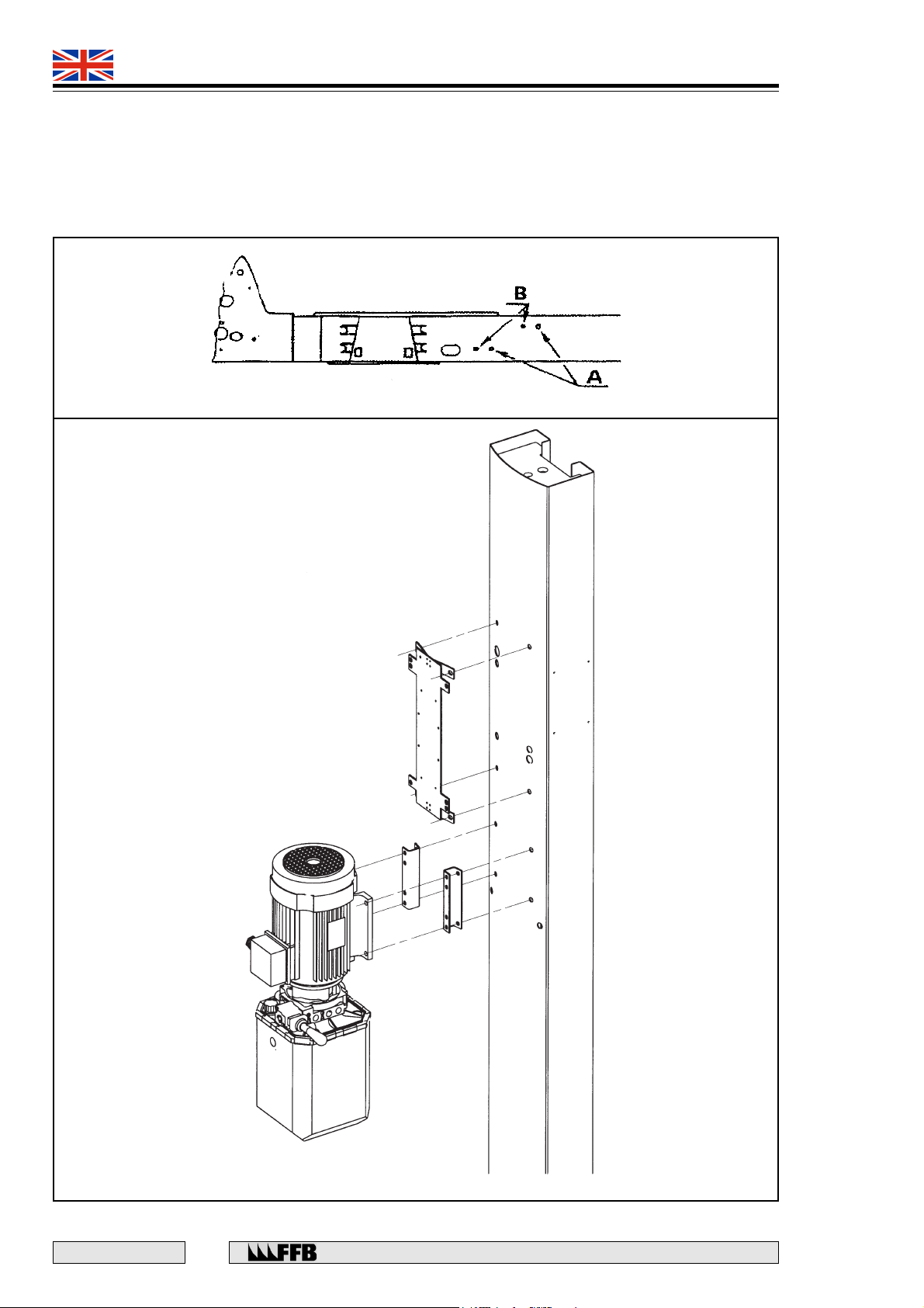
• At each end of the fixed track, remove the wire rope guide screws (Fig. 4).
• Unwind the wire ropes over a clean floor, they have a steel core and must not be subjected to any
kinking or bending during their installation. The ends of the wire ropes are colour-coded and should
be threaded over pulley grooves of the same colour as the rope.
Insert the following into the rectangular aperture on the cross-member beam 1-2:
• The loop of the white and yellow wire ropes to the left of the twin pulleys and then route it over the
crossbar, so that the yellow wire rope (the shortest) is uppermost.
• The end of the white wire rope to the right of the twin pulleys and then bring it along the track and out
through the rectangular aperture in the side of the cross-member 3-4.
• The loop of the red and blue wire ropes to the right of the twin pulleys and then route it over the crossbar
so that the red wire rope (the shortest) is uppermost.
• The end of the blue wire rope to the left of the twin pulleys and then in a similar way as the white wire
rope and out through the other end of the track.
• Attach the nylon roller by its shoulder screw onto the end of the crossbar, on the side of the red and blue
wire ropes (inner side of the platform).
• Remove the vertical pulleys from cross-member 1-2 and then feed the end of the red and yellow wire
ropes in through the beam until they reach their respective columns. Ensure that the wire ropes are
correctly positioned in the grooves of the twin pulleys and replace the three wire rope guide screws.
Rue du Pré Neuf - 58440 MYENNES FRANCE
11
E 167 - GB - 6
Page 12
493 9021
493 9031
QUADRA
At each end of the cross-member, feed the wire rope under the sensing roller which should always be kept
in the upper position, then insert it into the groove of the vertical pulley and then insert the end of each wire
rope through the top of the column, fit the shoulder collar and the two nuts.
In a similar way, route the white and blue wire ropes in cross-member 3-4 and fit them to their respective
columns.
Fig. 4
Fig. 7
E 167 - GB - 6
12
Rue du Pré Neuf - 58440 MYENNES FRANCE
Page 13

493 9021
493 9031
QUADRA
Fitting the ladder racks
CAUTION: UNDER NO CIRCUMSTANCES SHOULD THE LADDER RACKS BE
PAINTED. IF NECESSARY, CLEAN THEM, SCRAPE OFF ANY EXCESS RUST
AND THEN COAT WITH THICK OIL.
The top of the platform must not be more than 300mm from the ground, when fitting the ladder racks.
On each column:
• Raise the wire rope sensing roller and retain in elevated position.
• Insert the ladder rack into the vertical cheek plate of the cross-member.
• Insert a stud bolt into the top of the column, screw a M16 locknut onto its lowest end, before
screwing it fully into the ladder rack. Then lock the nut into position.
• Fit the shoulder screw through the ladder rack then into the threaded hole at the base of the
column.
• Screw an M16 nut onto the top end of the bolt until the ladder rack no longer rests on the
shoulder screw at the bottom of the column, then add an M16 locknut.
Fitting the hydraulic hose and electrical connections - 493 9021
• Connect the high pressure hose onto the ram, forming a large loop around the horizontal
pulleys.
• Connect the oil return hose onto the ram.
• Bring the coiled electrical cable into the cross-member.
• Fit the conduit entry fittings at each end and fit them onto their respective brackets.
• Thread the two hoses and the electrical cable through the conduit.
• Attach the conduit support lug onto the track using two M8 x 16 screws with serrated lock
washers.
• Connect both the high pressure hoses and oil return hose onto the power-pack.
• Fix the conduit support lug onto the power-pack using a screw and serrated lock washer.
• Connect the electrical cable onto the mounting plate.
• Check that the circuit breaker has been set correctly as follows:
6.3 A in 400 V
10 A in 230 V
• Connect the two junction boxes mounted on the cross-members, using the designated cable.
Rue du Pré Neuf - 58440 MYENNES FRANCE
13
E 167 - GB - 6
Page 14
493 9021
493 9031
QUADRA
Fitting the hydraulic hose and electrical connections - 493 9031
• Connect the high pressure hose onto the auxiliary lifting ram in the adjustable track. The oil
return hose must be attached as soon as the auxiliary unit is mounted in position.
• Route the hoses into the chain and secure the chain along the cross-member using two M6 x 16
screws with serrated washers. Fit the angle bracket using two M8 x 16 screws with serrated
lock washers.
• Fit the inversion valve angle bracket onto the track using three M8 x 16 screws with serrated
lock washers.
• Connect the conduit and glands onto these two angle brackets.
• Connect the electrical cables into the junction boxes on the cross-members.
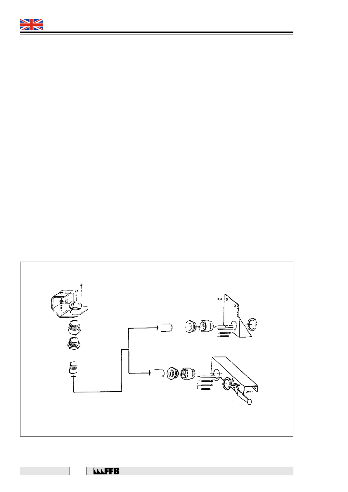
• Connect the HP hoses according to Fig. 11.
• Thread the HP and oil return hoses together with the electrical cable into the conduit and
connect them onto the power-pack.
• Fit the conduit angle bracket onto the power-pack using one M8 x 16 screw with serrated lock
washers.
• Connect the electrical cables onto the control panel.
• Check the settings of the circuit breaker are as follows:
6.3 A for 400 V
10 A for 230 V
LIFT 493 9021
LIFT 493 9031
Fig. 11
E 167 - GB - 6
14
Rue du Pré Neuf - 58440 MYENNES FRANCE
Page 15
493 9021
493 9031
QUADRA
CONNECTING TO THE ELECTRICITY SUPPLY
IMPORTANT: THE ELECTRICAL SUPPLY MUST CONFORM WITH THE
CURRENT EDITION OF THE IEE REGULATIONS.
The rating [SIZE] of the supply control fuses should be as follows:
- 230 V Three phase 10 A aM
- 400 V Three phase 6 A aM
The conductor section for the supply should be as follows:
VOLTAGE LENGTH OF LINE CONDUCTOR CROSS-SECTION
400 V less than 100 m 1.5 mm
100 to 150 m 2.5 mm
230 V less than 35 m 1.5 mm
35 to 55 m 2.5 mm
2
2
2
2
• Check that the transformer voltage and the circuit breaker rating and its settings all correspond
to the voltage. Connect the electrical supply to the control panel.
• Check that the fuse-holder mounted on the terminal block carries the correct fuse.
• Check the direction of rotation of the motor: rotate the circuit breaker to position 1, then observe
the direction of rotation of the motor fan by briefly rotating the control knob towards RAISE.
If the fan does not turn in a clockwise direction, isolate the electrical supply. Interchange two of
the phases in the electrical supply and re-check.
COMMISSIONING THE PUMP
Fill the pump unit reservoir with the correct grade of oil as follows:
493 9021 8 litres of S.A.E.: 10W30, 10W40 oil or hydraulic oil Ref. 4939031
493 9031 8 litres of hydraulic oil - ONLY USE that supplied with the lift (Ref. 256 8011)
Engler viscosity at 20 C : 4 to 4.5
NOTE: An extra two litres of oil will be required after the rams have been bled.
Tension the wire ropes by turning the control knob towards 'RAISE', checking regularly that none of the wire
ropes have slipped out of the pulley grooves. Raise the platform by about 100mm and check the following:
• That none of the wire ropes are fouling a metal part or an electrical cable.
• That the latches retract simultaneously when the control knob is turned towards 'LOWER'.
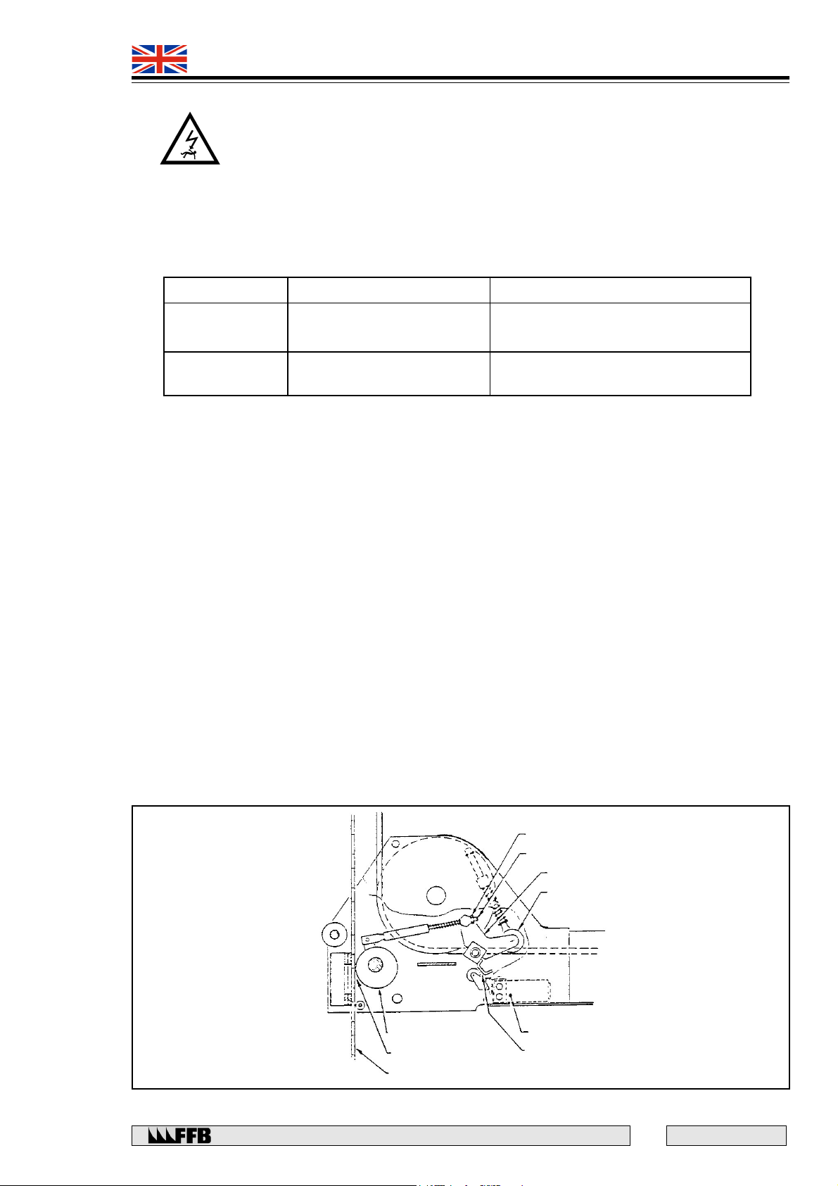
• At each end of the cross-member, check that there is clearance of between the limit switch roller
and the rocker arm cam (Fig. 12).
LOCKNUT
LOCKNUT
RETAINING ROD
RETAINING ROD
ROCKER
ROCKER
ROLLER
ROLLER
SWITCH
SWITCH
Clearance: 0 to 0.5 mm
Clearance: 0 to 0.5 mm
15
E 167 - GB - 6
Fig. 12
CAM
CAM
Clearance:1.2 to1.5 mm
Clearance: 1.2 to 1.5 mm
LADDER RACK
LADDER RACK
Rue du Pré Neuf - 58440 MYENNES FRANCE
Page 16
493 9021
493 9031
QUADRA
Fitting accessories
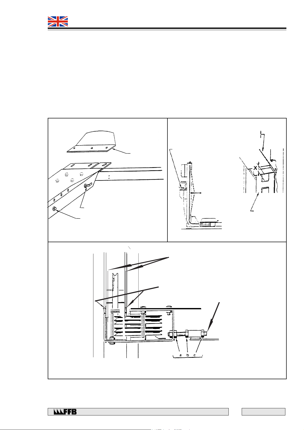
• Fit the blanking (inspection) plate to the end of each cross-member in the (fixed track) axis.
• Hang the access ramps onto the end of the tracks on the 'drive on' side, and then insert the
retaining rod into the hooks and locate and fit the split pins in position.
• Attach the end stops onto the tracks at the opposite end to the drive on direction. (Fig. 19).
• Fit the blanking plates onto the tracks.
Adjusting the level of the platform
Rest the platform on the latches at about 500mm from the ground and fully slacken the wire ropes by
operating the ‘LOWER’ lever for a short period, after the platform comes to a stop.
By adjusting the nuts on the ladder suspension stud bolts, check that the platform is level:
• laterally, using a spirit level on each of the cross-members
• longitudinally using a spirit level in the centre of a track
CAUTION: WHEN ADJUSTING THE NUTS ON THE LADDER SUSPENSION
BOLTS, CHECK THAT THE RETAINING SCREW ON THE LOWER END OF THE
LADDER RACK IS NOT CLAMPED IN ITS ELONGATED HOLE AND THAT THE
WIRE ROPE IS KEPT SLACK, IF NECESSARY, OPERATE THE ‘LOWER’ LEVER
FOR A MOMENT.
Adjusting the wire ropes
This adjustment is necessary in order to:
• prevent one or more of the wire rope safety switches from operating when the platform is in its
lowest position.
• allow the latches to be engaged simultaneously, by eliminating any stretch in the wire ropes
under load. NOTE: a long wire rope should be shortened more than a short one to
compensate for 'elastic' stretch.
CAUTION: WHEN ADJUSTING A WIRE ROPE NUT, ALWAYS HOLD THE END
OF THE WIRE ROPE FERRULE TO PREVENT THE ROPE TWISTING.
• Lower the platform to the ground. Release the button that unlocks the latches and then the
‘LOWER’ lever, after having pulled on the wire rope in column 4 (Fig. 13) so that the ram is
fully extended.
• Adjust each wire rope end in turn until a measurement of 62 +/- 2 mm is obtained between the
bottom of the cross-member cheek plate and the top of the column base plate. A clearance of
7 to 10 mm is to be obtained between the bottom of the cheek plate and the lower column stop
(1 turn of the nut = 2 mm).
• Position a vehicle weighing approx. 2,500 kg on the platform and raise it to eye level, leaving
it suspended on the wire ropes.
• Measure the dimension 'X' (See Fig. 13) for each column and identify the highest cross-member
end in relation to the ladder slots.
• Raise the other ends by turning the nut on the wire rope end fitting until they are brought
to the same level as the highest end (1 turn of the nut = 2 mm).
• Fit a and fully tighten locknut onto each wire rope.
• Fit the column covers in position.
E 167 - GB - 6
16
Rue du Pré Neuf - 58440 MYENNES FRANCE
Page 17
493 9021
T
493 9031
QUADRA
Fitting and adjusting the tie rods
Raise the platform, without letting it rest on its latches. At each end of the fixed track:
• Insert the threaded rods into the tubes located in the track (Fig. 15).
• Screw two M12 nuts (a) and (b) onto the rod.
• Position an M12 nut in the cross-member cheek plate. Tighten the M12 nut (a) fully against
the bracket.
• Screw a M12 nut (c) onto the other end.
• Adjust nuts (b) and (c) until the flanges of the vertical cheek plate are parallel in the column
and tighten them fully.
Cross member
vertical gusset
FIXED END-STOP
2 WAY VALVE
for levelling
SOLENOID
Emergency lowering
Fig. 19 Fig. 13
CHEEKPLATE FLANGE
CHEEKPLATE FLANGE
PLASTIC STUD
PLASTIC STUD
‘LOWER’ Lever
Ladder
Fig. 15
NUT M 12
Rue du Pré Neuf - 58440 MYENNES FRANCE
NUT M 12
TIE BOL
THE BOLT
17
E 167 - GB - 6
Page 18

493 9021
493 9031
QUADRA
Checking the column adjustment
Raise the unloaded platform to 300mm from the ground, suspended by the wire ropes.
Check the following:
• That each column is square, using a rule placed firmly on the outer surface, and which is then
used to sight the opposite column.
• That each column is centred on its cross-member cheek plate to prevent excessive friction on the
plastic studs on the column aperture.
• That the clearance between each cross-member and column is between 1 to 3 mm.
• That each column is vertical, by means of a plumb line. In order to eliminate any clearance
between cross-members when the platform is in its operating position, the distance between the
tops of the columns of one particular cross-member must be slightly less (5 to 15 mm).
NOTE: If a cross-member is too tight between columns, an unladen platform could jam when
being lowered, causing the wire rope to slacken and the latches to engage in the ladders.
If necessary, adjust the position or the vertical plane of one or more columns, by placing shims under the
base plate and adjusting one or more of the tie-rods under the ends of the fixed track.
Check inside the columns with the platform at three different heights e.g. low, medium, high, that the ladder
edges do not rub on the inner surfaces of the cheek plate flanges.
Checking the latches
With the platform raised and suspended on the wire ropes, check at each end of the cross-members that the
latch operates freely without sticking. If necessary, identify the cause of the problem and rectify (e.g. rust,
using too thick an oil to lubricate it, latching solenoid sticking due to ingress of dirt etc.)
Checking the rocker arm retaining system
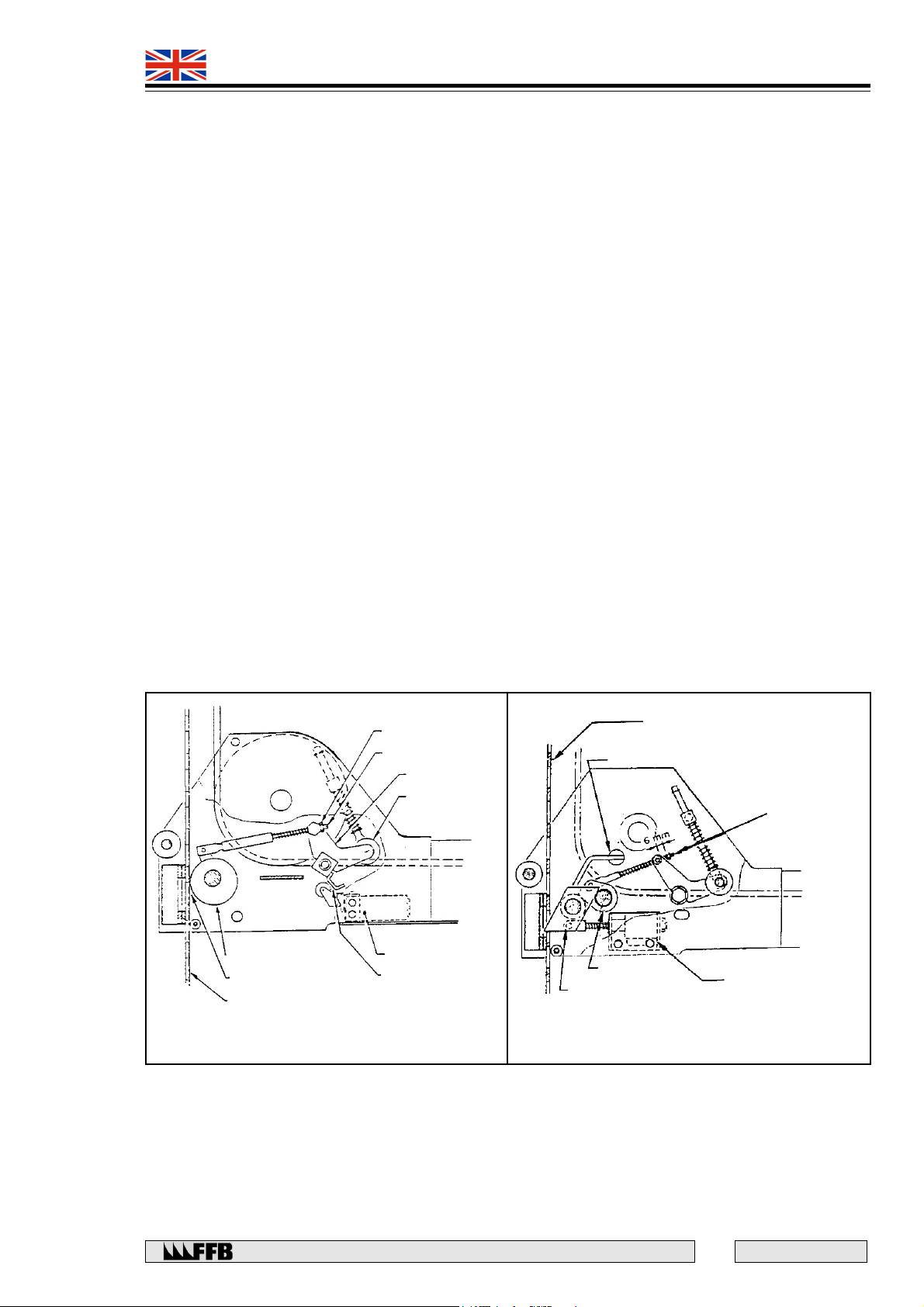
With the unloaded platform raised and suspended on the wire ropes, proceed as follows at each crossmember end:
• Pull on the retaining rod to check that the bush turns freely.
• Check the rod clearance (Fig. 17). This clearance must be 6 mm. Correct if necessary by
adjusting the stop nut on the end of the rod.
Checking the safety brake cam
With the unloaded platform raised and suspended on the wire ropes, proceed as follows at each cross-member
end:
• Measure the clearance between the cam and the ladder rack. This should be between 1.2
and 1.5 mm. If necessary, release the locknut and adjust the cam retaining rod (See Fig. 12)
and check that the cam turns freely.
Checking the wire rope safety switches
The tension of each platform suspension wire rope is monitored at each end of the cross-member by a
sensing roller mounted on a rocker arm.
If one of the wire ropes becomes slack because of an obstacle under the platform or a broken wire rope, the
corresponding rocker arm pivots and activates the first contact on the switch which in turn causes the latches
to become engaged, thereby stopping the platform. The second contact is also activated and this prevents
the platform from being raised again.
If, when the platform is being lowered onto the latches, these do not engage in the same ladder slots on the
same horizontal plane, or if one of the latches engages unintentionally when the lift is being lowered, the
supporting latch retaining system restricts the rotation of the rocker arm in such a way, that only the first
electrical contact on the switch is actuated. This causes the other latches to engage.
NOTE: It is still possible to raise the platform again in order to re-adjust the platform so that it is level.
E 167 - GB - 6
18
Rue du Pré Neuf - 58440 MYENNES FRANCE
Page 19
493 9021
mm
493 9031
QUADRA
Checking the adjustment of the wire rope safety switch
With the unladen platform raised and suspended on the wire ropes, check at each cross-member end that
there is a clearance of approx. 0 to 0.5 mm between the switch roller and the cam that is part of the sensor.
If necessary, adjust the position of the switch in order to obtain this clearance (Fig. 12).
Checking the obstruction/wire rope failure sensor
• Place an obstruction under one end of a cross-member.
• Lower the platform until the latches fall back against the ladders and the lift stops.
• Check that it is no longer possible to operate the RAISE control. If necessary, check the switch
position and electrical circuit.
• In order to free the obstruction, raise the sensing roller, then whilst keeping it raised, rotate the
control knob towards RAISE, until this obstruction can be removed.
• Repeat this sequence for all of the cross-member ends.
Checking the ladder latching
With the unloaded platform raised and suspended on the wire ropes, check each cross-member end as
follows:
• Disconnect one conductor from the latch solenoid and then start to lower the platform until the
latches fall back against the ladders and the platform is stopped. The latter must occur before
there is a 100 mm maximum offset between the heights of the cross-member ends. Ensure that
this is correct and check that the ‘RAISE’ command is still possible.
If the results of one of these tests are not satisfactory, bring the platform back to level, suspended on the wire
ropes and then check the 6 mm clearance of the retaining rod (see Fig. 17), as well as the switch position
and electrical circuit.
Reconnect the solenoid and then check another end.
LOCKNUT
LOCKNUT
RETAINING ROD
RETAINING ROD
ROCKER
ROCKER
ROLLER
ROLLER
LADDER RACK
VISUAL FLAG
RETAINING
ROD
SWITCH
CAM
CAM
Clearance: 1.2 to
Clearance: 1.2 to 1.5 mm
1.5 mm
LADDER RACK
LADDER RACK
SWITCH
Clearance: 0 to
Clearance: 0 to 0.5
0.5 mm
RING
LATCH
ELECTROMAGNET
Fig. 12
Fig. 17
Rue du Pré Neuf - 58440 MYENNES FRANCE
19
E 167 - GB - 6
Page 20
493 9021
493 9031
QUADRA
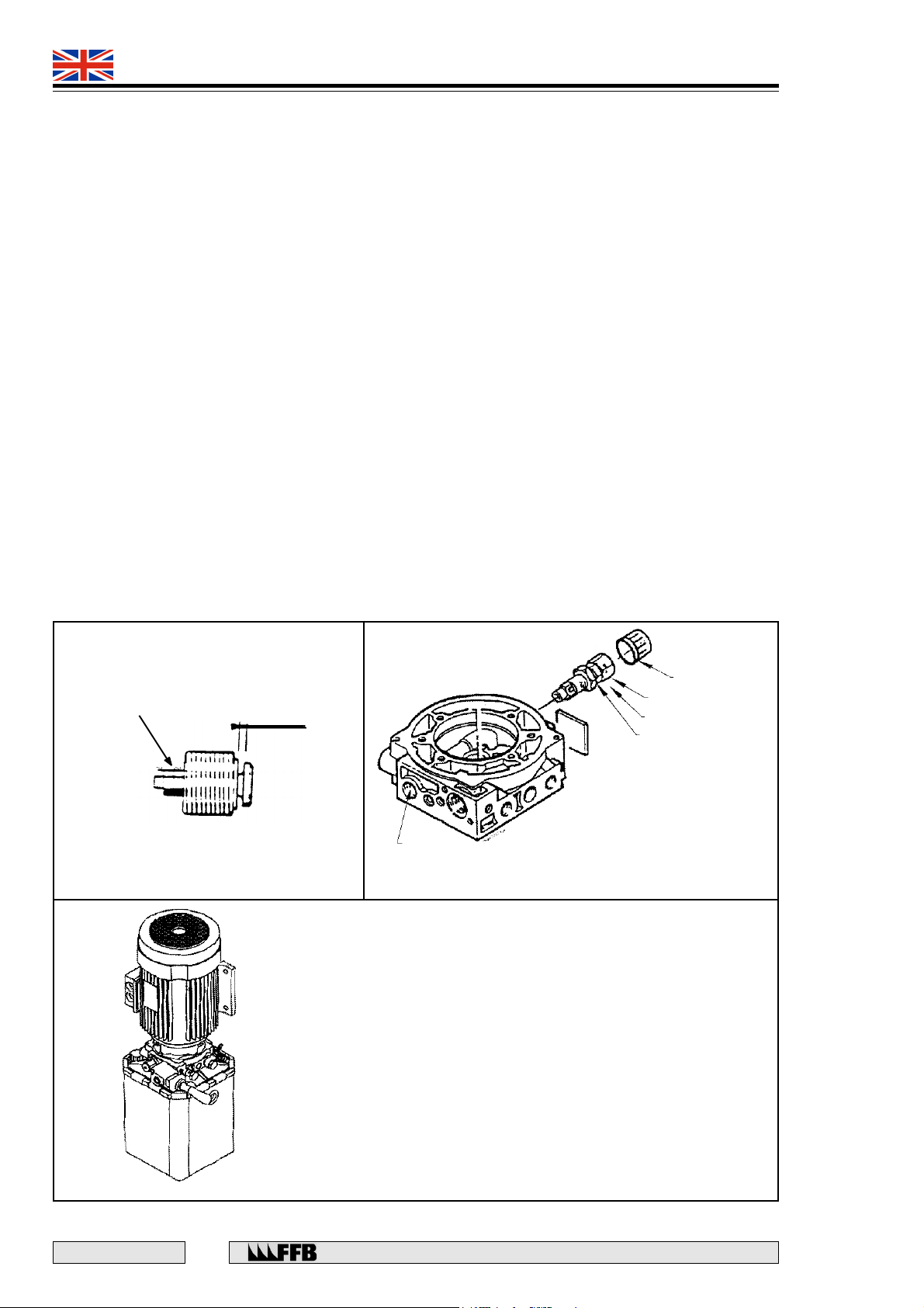
Checking the ram safety valve
Should a hose fail, this valve stops the lift from lowering by locking up the fluid in the ram. Correct operation
of this valve is depends on the correct oil grade/viscosity, it should be checked whether the oil is of the
correct grade before carrying out this test. If it is too cold, fully raise the loaded platform a few times.
In order to check the valve setting:
• Place a FOUR Tonne load onto the platform and then raise it.
• Slowly move the ‘LOWER’ lever and mark its position as soon as the valve operates (about 3/4
of the way).
• Raise the platform again to its uppermost position.
• Move the ‘LOWER’ lever until it is brought slightly in front of the previously marked position so
that the valve is not made to function. Record the time it takes to lower the platform fully. This
should be between 23-26 secs.
• If it is necessary to adjust its setting, refer to Fig. 16.
NOTE: This valve must function with a load of 300 kg on the platform. The bursting of a hose can be
simulated by opening a valve that has been fitted between the hose and the power-pack.
Lubrication
Lubricate as following parts:
• The platform load bearing wire ropes with the special grease supplied.
• The cam, latch and wire rope sensor pins.
Fit the cheek plate covers onto the cross-member ends.
Adjusting
nuts
Fig. 16
0.5 mm
Pressure
gauge port
Fig. 20
A hydraulic power pack includes :
4 920 1604 14,4 x 18,1,5 copper seal
2 920 1613 M14 x 150 hollow bolt
1 920 1625 D6 Banjo adapter
1 937 1268 Motor 1,8 Kw / 2750 r.p.m
1 942 0067 Hyd Pump unit HPI 2cc
1 993 4109 120 x 180 Plastic pocket
1 Procedure adjustment limiting device
(See at the end of the document)
Fig. 21
Tamper-proof
Cap
Cap nut
Adjustment screw
Locknut
Replacement tamper-proof cap
Part No. 9420081
E 167 - GB - 6
20
Rue du Pré Neuf - 58440 MYENNES FRANCE
Page 21
493 9021
493 9031
QUADRA
COMMISSIONING THE AUXILIARY LIFT
• Turn the handle on the three way valve to ‘AUXILIARY’.
• In the enclosure (X5), put a link wire between terminals 8 and 9 in order to deactivate the
photo cell.
• Rotate the control knob towards RAISE so that the drive ram fills with oil.
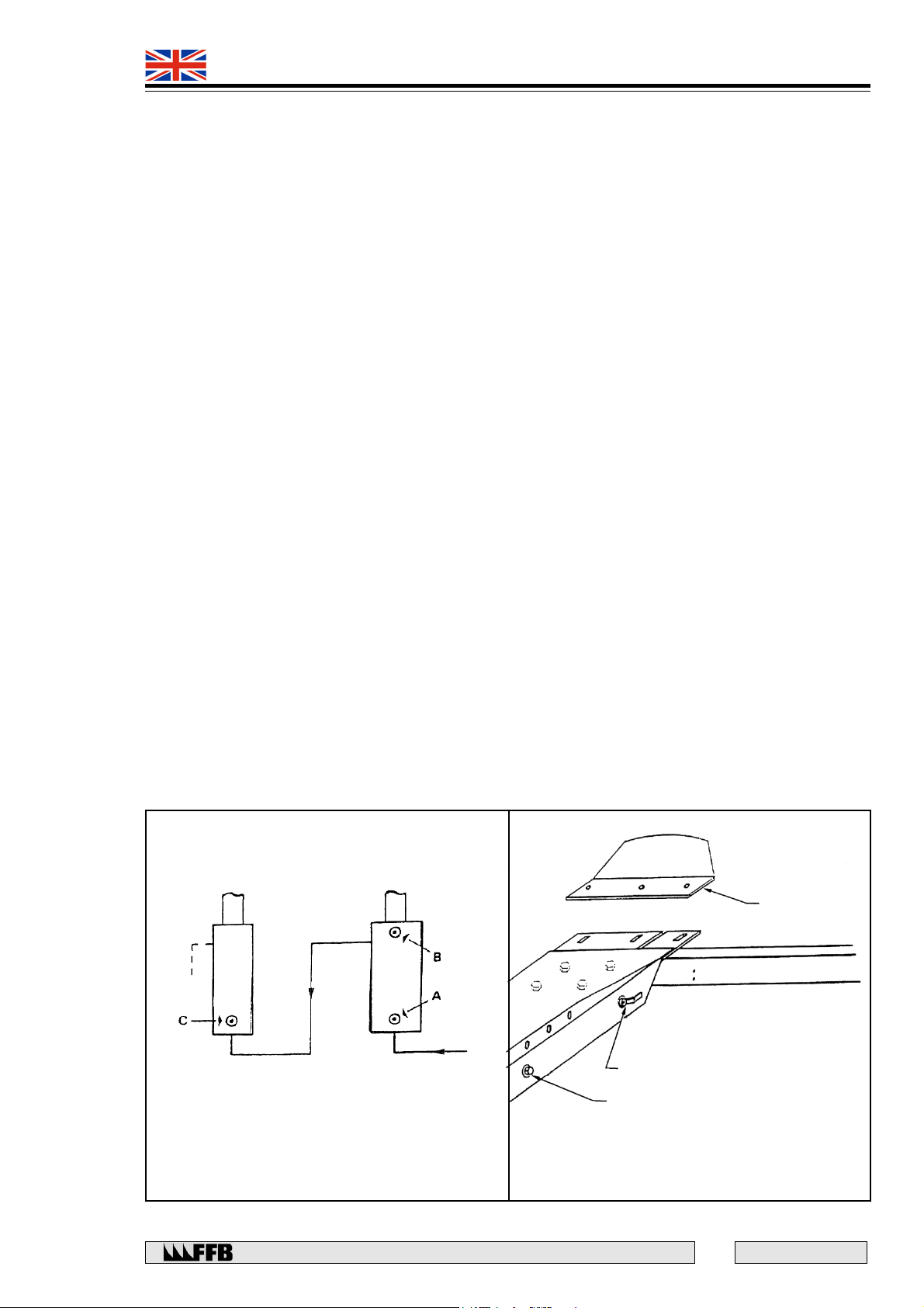
• Open bleed screw (A Fig. 18) on the drive ram to expell any air in the system, when this is
completed re-tighten the bleed screw and check for leaks.
• Open the two way valve located on the inside of the fixed track (Fig. 19).
• Rotate the control knob towards RAISE, so that the slave ram fills with oil.
• Connect the oil return hose onto the ram.
• As above, open the two bleed screws (B) and (C), on the rams, to expell any air in the system,
when this is completed, re-tighten them and check for leaks. Operate the system, to fully extend
the slave ram.
• Close the two way valve again on the inside of the fixed track and lower the platform by
rotating the control knob to LOWER and opening the bypass valve.
• At about 150mm from the track upper surface, the auxiliary will stop lowering and the buzzer
will sound.
• Release the rotary control knob and activate it again in order to start lowering the auxiliary
again.
• Raise and lower the auxiliary several times and check if the two platforms are at the same
height (a slight offset under load is acceptable).
If correction is necessary, this can be achieved by increasing or decreasing the spare oil
capacity between the two rams by means of the two way valve.
• Adjust the light beam of the photo cell onto the reflector (taking into account a slight offset
under load).
• Remove the link (8 - 9) wire in (X5).
NOTE: The buzzer sounds as soon as the auxiliary lift reaches its lower limit switch.
It is also normal for it to operate whilst the lift is lowering.
SLAVE DRIVE
Fig. 18
Rue du Pré Neuf - 58440 MYENNES FRANCE
Fig. 19
2 WAY VALVE
for levelling
SOLENOID
Emergency lowering
21
FIXED END-STOP
E 167 - GB - 6
Page 22

493 9021
493 9031
QUADRA
OPERATION
Safety instructions
(The following information must be displayed on a label on the control column)
• The danger zone is the area around and including the lift. This can be defined by a 50mm wide
450 yellow/black line or self-adhesive tape, a minimum of 600mm around the outer edges of the lift
column bases and access ramps.
• The tracks and floor within the danger zone must always be kept perfectly clean.
• The vehicle must be effectively secured using chocks if applicable.
• Ensure that the vehicle is structurally able to be lifted at points specified by the vehicle manufacturer.
• Only authorised competent persons can use the lift.
• The operating instructions should be referred to, particularly in the case of a breakdown.
• The operator must ensure that the displacement area (danger zone) for the lift and the load, is clear
of any personnel tools and equipment before the lift is operated.
• The operator must ensure that the methods used for lifting the vehicle comply with the requirements of
the vehicle manufacturer and does not present any risks. The operator must also check that the
vehicle is correctly and securely positioned and structurally suitable to be lifted on the points
specified by the vehicle manufacturer.
• The operator must stop the lift after the platform has risen about 250mm and re-check the vehicle
stability, lifting points/security etc. before continuing to raise the platform to the desired height.
• The operator must supervise the entire lifting operation and is responsible for safety of the lift and
the load, each time the lift is operated.
• Do not enter the displacement area (danger zone) when the lift is operated.
• Check that the latches are engaged in the ladder racks before going beneath the platform.
DO NOT WORK UNDER AN UNLATCHED PLATFORM.
• It is forbidden for persons to ride on the platforms.
• Do not carry out any work to a vehicle that may cause it to become unstable, slide or fall from the
platforms i.e. remove heavy components or apply an undue force.
• Keep all children and animals away from the displacement area (danger zone).
• During prolonged shut-down periods (e.g. nights, weekends, holidays) it is advisable to turn on the
emergency stop switch housed in the electrical enclosure (position 0). The switch can be locked in
this position, in order to prevent the lift from being used by non-competent persons.
• The use of personal protective equipment e.g. gloves, goggles etc. may be necessary when working
within the danger zone.
Positioning the vehicle
• Position the vehicle and check that the track width corresponds to the track of the vehicle.
• Drive the vehicle onto the platform and secure it using chocks placed on both sides of at least one
wheel (see ‘Accessories’).
Raising the platform
• Set the three way valve to ‘LIFT’ (493 9031).
• If necessary, turn off the emergency stop switch (position I).
• Rotate the control knob towards ‘RAISE’. Hold it there, until the platform is at the desired height.
• Actuate the ‘LOWER’ lever so that the latches engage in the ladder slots; only release it when the
platform is secured. If the platform starts to tilt, due to a latch not being able to engage in the
ladder, raise the platform and then lower it again.
E 167 - GB - 6
22
Rue du Pré Neuf - 58440 MYENNES FRANCE
Page 23
493 9021
493 9031
QUADRA
Lowering the platform
• Check that there are no personnel, tools or equipment in the danger zone.
• Raise the platform 20-30mm to allow the latches to be released.
• Turn the control knob towards ‘LOWER’ and whilst holding it there, progressively operate the
‘LOWER’ lever. NOTE: Whilst the platform is being lowered, it is normal for the buzzer to be heard
if the auxiliary is in its bottom position.
Stopping the platform before the reaching the floor.
• Release the control knob and then the lever when the platform is latched.
Ensure the platforms have latched correctly if required (See above).
Stopping the platform at ground level.
• Wait for the platform to come to rest before releasing the control knob and the lever.
NOTE: If, whilst being lowered, the platform comes to rest without the latches being engaged in the ladder
slots - the lower ever has been operated ‘excessively’ causing the ram safety valve to operate. If this
happens, raise the platform for a few seconds and then recommence lowering the platform by operating the
lever more moderately, so that this problem is not repeated. If this locking occurs when the platform is at its
highest point and cannot be raised any further, remove the upper limit switch so that it does not operate.
CAUTION: WHEN THE PLATFORM COMES TO REST AT FLOOR LEVEL, THE LATCHES
SHOULD NOT ENGAGE WITH THE LADDER RACK (BEFORE THE BUTTON IS RELEASED).
WIRE ROPES THAT ARE INCORRECTLY ADJUSTED MAY ALLOW THE SAFETY SWITCHES
IN THE CROSS-MEMBERS TO OPERATE. IF THIS HAPPENS, THE WIRE ROPES MUST BE
CORRECTLY ADJUSTED BEFORE POSSIBLE TO RAISE THE PLATFORM.
RAISING THE AUXILIARY PLATFORMS (493 9031)
• Ensure that the vehicle is ‘structurally suitable’ to be lifted at the points recommended by the vehicle
manufacturer.
• Set the three way valve to ‘AUXILIARY’.
• Insert the rubber blocks between the auxiliary plate and the vehicle body. (See ‘Safety Precautions’)
• Turn the control knob towards ‘RAISE’ and hold it there until the desired height is reached.
IMPORTANT: If the motor does not operate, check that the upper limit switch has not been actuated by the
platform. Similarly the upper limit switch of the auxiliary lift prevents the platform from being raised.
LOWERING THE AUXILIARY PLATFORMS (493 9031)
• Check that there the danger zone is clear of personnel, tools and equipment.
• Check that there are no obstructions or tools are left under the auxiliary platform.
• Turn the control knob towards ‘LOWER’. Whilst holding it there, progressively operate the
‘LOWER’ lever. The lift stops 150mm from the bottom and the buzzer operates.
• Release the control knob and check that it is safe to lower the platform completely.
• Continue lowering.
‘LOWER’ CONTROL
Changing the position of the lever
After being in use for some time, the end of the ‘LOWER’ lever may start to touch the motor. In order to change
its position, ensure that the needle is locked in place on its seat, unscrew the lever a few turns then turn it to the
correct position, then re-screw and firmly tighten the lever in position.
CAUTION: CHECK THAT THERE IS CLEARANCE OF 1 TO 2 MM BETWEEN THE
UPPER END OF THE SPRING TUBE AND THE SUPPORT, WHEN THE NEEDLE IS
LOCKED ONTO ITS SEAT.
Rue du Pré Neuf - 58440 MYENNES FRANCE
23
E 167 - GB - 6
Page 24
493 9021
493 9031
QUADRA
RAM SAFETY VALVE
This valve is located in the hydraulic supply in the base of each of the rams. Should the supply hose rupture,
the valve stops the platform from being lowered by trapping the oil in the ram.
NOTE: If the valve in the slave ram is operated (in the right-hand track), the solenoid valve causes the lefthand track to be brought to rest (this solenoid is controlled by the photoelectric control sensor).
Before replacing this valve, check the following:
• Poor adjustment of the flow rate controller causing the platform being lowered too quickly.
• An incorrect grade of oil has been used.
Check and adjustments
• Raise the platform half-way.
• Unscrew the hose and its connector see following warning.
WARNING: CARE SHOULD BE TAKEN DUE TO THE RESIDUAL OIL PRESSURE
IN THE RAMS. THE APPROPRIATE PERSONAL PROTECTIVE EQUIPMENT E.G.
GLOVES AND GOGGLES SHOULD BE WORN.
• Unscrew the valve using a special tool (Ref. 150031).
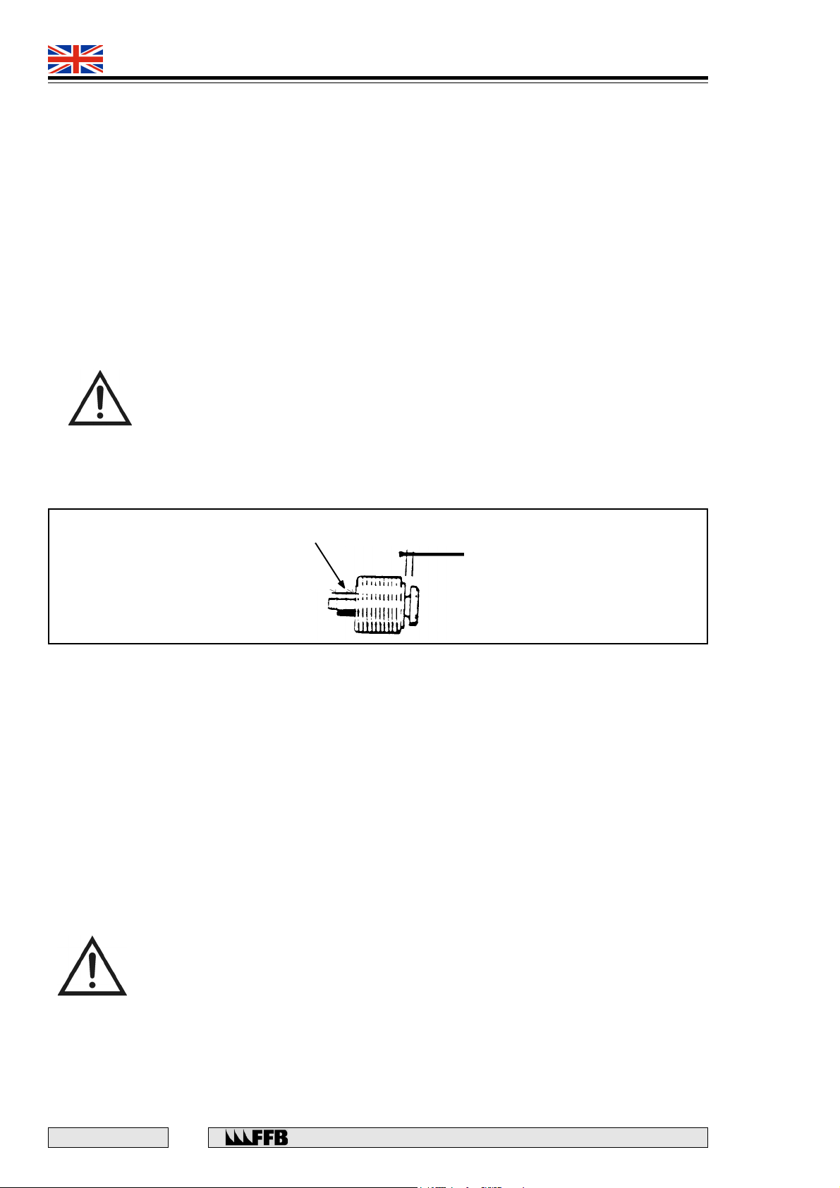
• Check that the clearance is 0.5 mm. If necessary, adjust the nuts to obtain this clearance (Fig. 16).
• Replace the valve in the ram, screw it in fully and then re-fit the hose and its connector.
Adjusting
nuts
0.5 mm
Fig. 16
Thread torque
• The inside screws of the banjo connector must be tightened to a torque of 3 to 4 m/kg.
• Whenever the parts are re-assembled, it is important to always replace the copper seals.
LOWERING THE PLATFORM without electrical power
If the electrical supply has been interrupted, it is still possible to lower the platform by proceeding as follows:
• Remove the upper and lower covers on the vertical cross-member cheek plates.
• Raise one cross-member end with a crane or a jack until it is possible to manually extract the latch
from the ladder slot.
• Use steel wire to keep the latch retracted. Raise the sensing roller in order to unlock the cam (check
it) and whilst keeping it raised, re-lower the cross-member end. Repeat this procedure for the other
cross-member ends.
• Operate the ‘LOWER’ lever moderately so as not to cause the safety valve to function again.
CAUTION: STOP LOWERING THE PLATFORM IMMEDIATELY IF A CROSS-MEMBER
END, STOPS MOVING BECAUSE THE SAFETY BRAKE CAM HAS OPERATED.
If the safety brake cam of one of the cross-member ends is actuated, lift the end using a shop crane or a jack,
and then manually lift the wire rope sensing roller. Unlock the cam and lower the cross-member whilst keeping
the sensing roller raised. As soon as the platform reaches the ground, drive the vehicle off and at each end of
the cross-member, release the latches and re-fit the cheek plate covers.
E 167 - GB - 6
24
Rue du Pré Neuf - 58440 MYENNES FRANCE
Page 25
493 9021
493 9031
QUADRA
LOWERING THE AUXILIARY (493 9031) platforms without electrical power
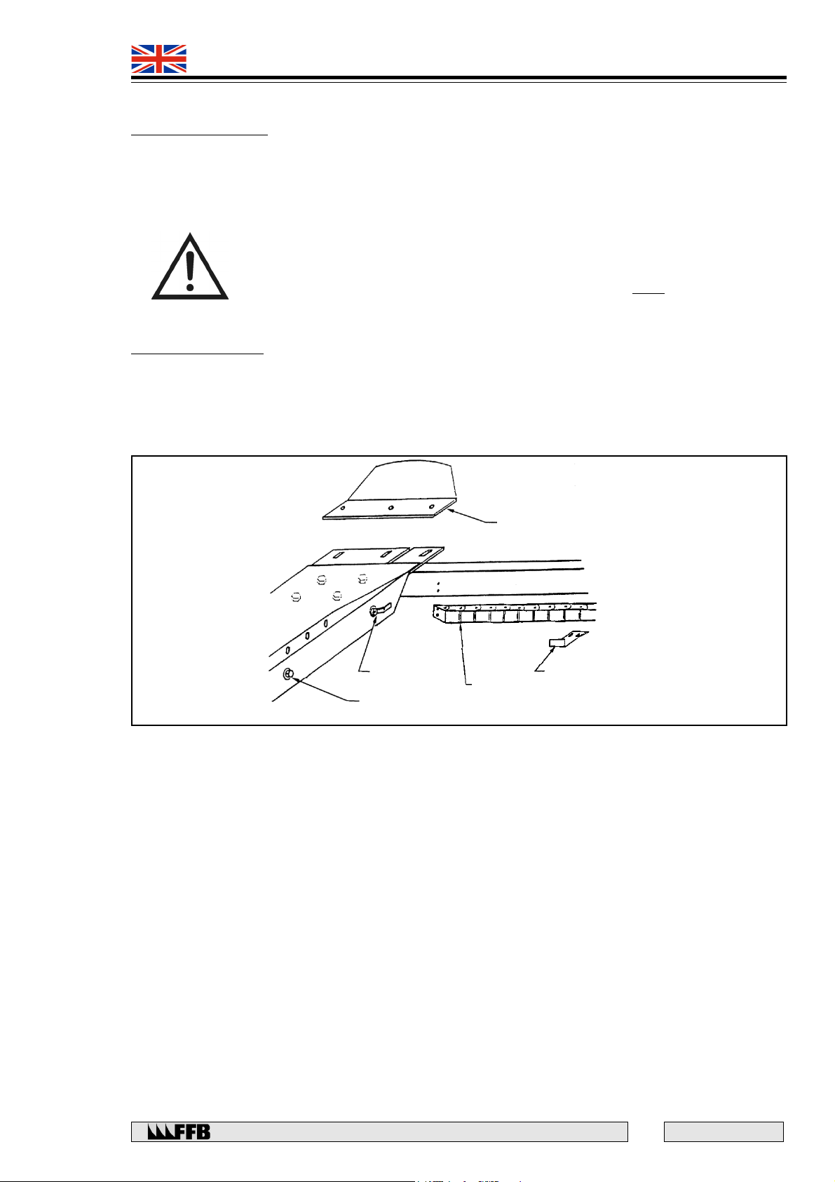
HYDAC solenoid valve
• On the inside of the fixed track there is a manual control for the oil solenoid valve for the auxiliary
(Fig. 19).
• Insert a 4 mm diameter pin into the end of the solenoid core.
• Using a large screwdriver to push on the pin, pull out the core and hold it locked in this position.
DANGER: CHECK THAT THERE ARE NO PERSONNEL, TOOLS OR EQUIPMENT
IN THE DANGER AREA, AS THE BUZZER WHICH NORMALLY SOUNDS TO
WARN OF THE RISK OF HANDS BEING TRAPPED, WILL NOT OPERATE.
• Remove the screwdriver and the pin.
EV HPI Solenoid valve
• Using a 6 x 4 Allen key, remove the screw situated on the end of the solenoid core through the 25
mm diameter hole on the inside of the fixed track.
• Replace the screw and tighten it to a torque of 0.3 m/kg.
Fig. 19
2 WAY VALVE
for levelling
SOLENOID
Emergency lowering
FIXED END-STOP
SUPPORT LUG
CHAIN
Rue du Pré Neuf - 58440 MYENNES FRANCE
25
E 167 - GB - 6
Page 26
493 9021
493 9031
QUADRA
MAINTENANCE
General
The lift and suspension parts (wire ropes) and safety systems must be examined at least every six months by
an authorised competent person More frequent checks will be necessary if the lift is continual use.
The lift must be thoroughly examined following any major repair or modification involving its main components.
These tests and examinations must only be carried out by an authorised competent person. The result and
date of this test or examination as well as the name, occupation and address of the person who has carried
it out, must be recorded in a log or notebook that includes the identification details of the lift.
Monthly Maintenance (or three-monthly if the lift is used infrequently)
• With the platform on the ground, check the oil level, or once a year, drain the oil reservoir.
Use the following types of oil:
- 493 9031 (including auxiliary lift)
Only use hydraulic oil ref. 256 8011, 5 litres Engler viscosity = 4 to 5 degrees at 20° C.
- 493 9021 (without auxiliary lift) hydraulic or engine oil S.A.E. 10 W 30.
• Lubricate the cam, latch and wire rope sensor pins with a light oil.
• Clean the platform suspension wire ropes. Check that no wire rope has come out of the pulley
grooves and inspect each rope over its entire length.
NOTE: a thin or frayed wire rope must be replaced.
• Check that there are lock nuts on the wire rope end fittings. Using the appropriate personal
protective equipment e.g. gloves, generously grease the wire ropes with the recommended
grease.
Annual lift test
Check the wire rope adjustment as follows:
• Place the unloaded platform in its bottom position and ensure that no cross-member end is
resting and causing mechanical wear on the column base plate. (NOTE: The distance between
the bottom of the cheek plate and the top of the base plate must at least 60 mm).
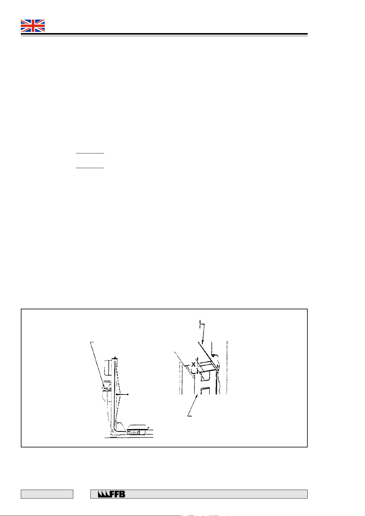
• Position a vehicle weighing between 1500 kg and 2200 kg on the platform. Raise the
platform to eye-level, suspended on the wire ropes and check that dimension X (Fig. 13) is
more or less the same for all four columns. If necessary, adjust the wire ropes.
Cross member
vertical gusset
‘LOWER’ Lever
Fig. 13
E 167 - GB - 6
26
Ladder
Rue du Pré Neuf - 58440 MYENNES FRANCE
Page 27

493 9021
493 9031
QUADRA
• Check the columns and the tie-rods under the ends of the fixed track.
• Replace the plastic studs that guide the vertical cross-member cheek plates into the columns, if
they are worn.
• Clean and wipe dry the ladders, then rub them with an oiled rag to protect them from rust.
• Check torque setting of the column anchor bolts.
• Check that the platform is level.
CAUTION: IT IS IMPERATIVE THAT THE WIRE ROPE IS READJUSTED WHENEVER A
MAINTENANCE OPERATION IS CARRIED OUT ON A LADDER RACK.
• Check the pulleys for wear.
• Turn the control knob towards ‘RAISE’ until the wire ropes are taut and then check that none of
the wire ropes have come out of their pulleys.
Check the following on the power-pack unit:
• The tension and condition of the return spring for the LOWER lever. If it is weakened or has
deteriorated, its return will no longer be automatic. If necessary, re-tension or replace the spring.
• The presence of a lead seal on the pressure relief valve. If necessary check its settings.
• In each cross-member end, raise the wire rope sensing roller using a hook to check that it turns
freely and does not have any flats.
Check whether the following parts of the rope safety system are operating correctly:
• The rocker retaining system and adjustment.
• The latches and cams together with their adjustment.
• The wire rope safety switches.
• The upper limit switch.
• The setting and operation of ram safety valve.
Check the following:
• Condition of the flexible conduit.
• Condition and operation of the access ramps.
• Condition and cleanliness of the tracks.
Check that the following are available:
• Moveable chocks (for securing the vehicle onto the platform).
• Safety sign notice.
• Maximum lift load notice.
Lift 493 9031
• Check that the auxiliary lift is level.
• Check that the photocell is adjusted and operates correctly.
• Check the condition of the auxiliary lifting pads.
OVERLOAD TESTS
The European Machinery Directive requires that all lifts are tested under dynamic (+10%) and static (+25%)
overload conditions prior to their commissioning. These tests must be carried out only an authorised
competent person. The result and date of these tests as well as the name, occupation and address of the
person who has carried them out, must be recorded in a log or notebook that includes the identification
details of the lift.
CAUTION: DURING THESE TESTS, THE SETTING OF THE PRESSURE RELIEF
VALVE SHOULD BE ALTERED FOR THE DYNAMIC TEST AND THEN RE-SET.
THE LIFT MUST NOT BE OPERATED DURING THE STATIC TEST.
Rue du Pré Neuf - 58440 MYENNES FRANCE
27
E 167 - GB - 6
Page 28
493 9021
493 9031
QUADRA
FAULT FINDING
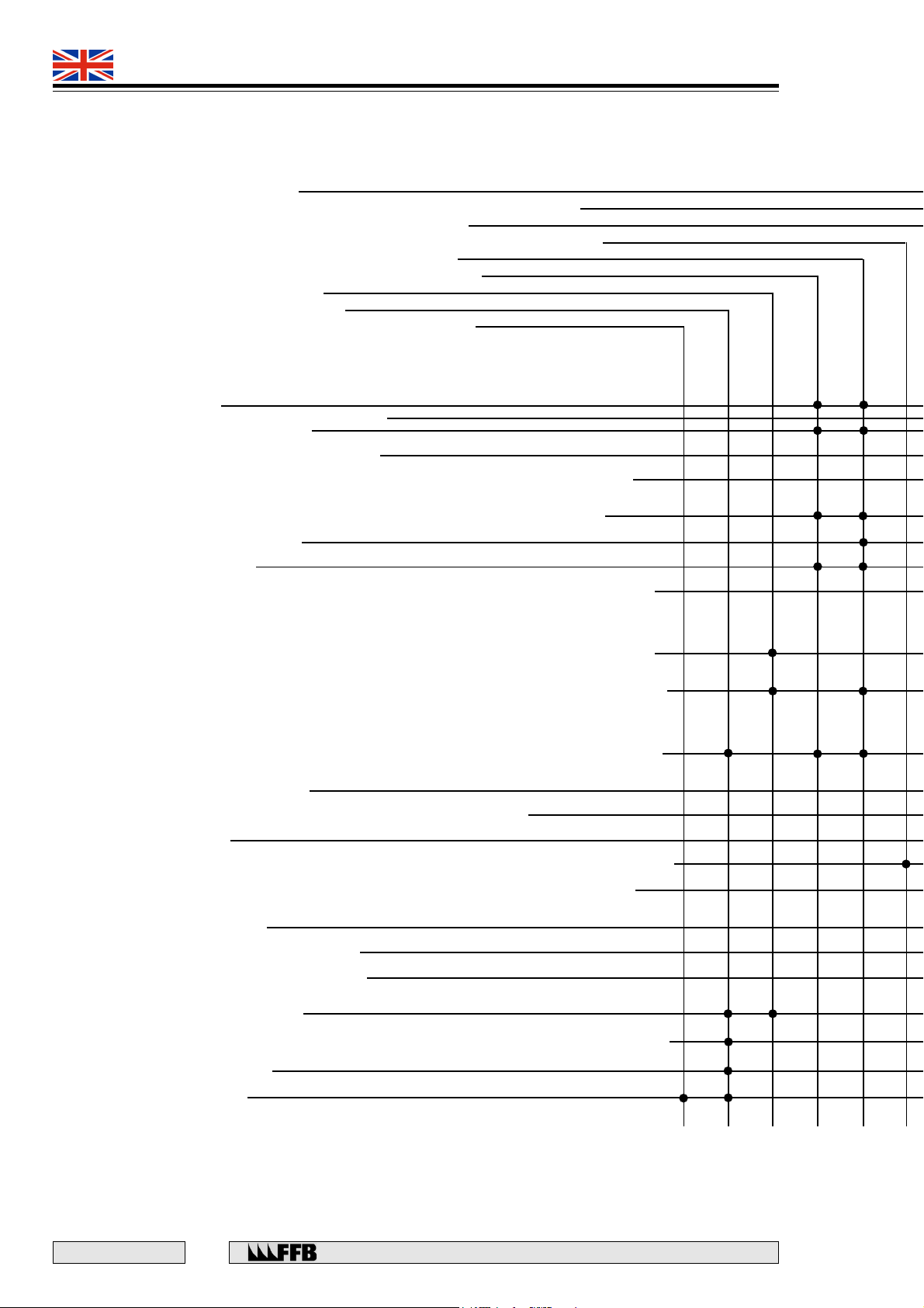
FAULTS
On turning the control knob towards ‘RAISE’:
• The pump does not operate
• The pump works but the platform or the auxiliary raises slowly or not at all
• The platform or the auxiliary does not lift to its full height
• An unusual sound occurs when the deck or the auxiliary reaches its upper limit
• When the deck is being lowered, it stops unexpectedly
• When the auxiliary is being lowered, it stops unexpectedly
• Unable to start to lower the deck
• Unable to start to lower the auxiliary
• When the auxiliary is being lowered, it moves very slowly
CAUSES
1) No electricity supply to the lift due to
2) Tripping of the motor circuit breaker (emergency stop)
3) The platform is at ground level and poor adjustment of the wire ropes has allowed the rocker arm to
activate the safety switch.
4) The ‘LOWER’ lever has been moved too far which has caused the ram safety valve to function.
5) Failure of a platform support wire rope
6) Failure of the ram supply hose
7) The platform is resting on its latches. One or more of the wire rope safety switches have been activated
due to poor adjustment of the rocker retaining system clearance and the clearance of the switch.
8) A latch will not unlock and the functioning of the electrical safety device has caused the other latches to
fall back against the ladder racks.
9) An obstruction under the platform or the safety brake cam on one of the cross-member ends unexpectedly
operates.
10) A component in the electrical circuit is faulty (e.g. fuse, transformer, contactor coil, switch) or one of the
conductors is disconnected or poorly connected.
11) The vehicle is too heavy (unusual noise)
12) Due to work on the power supply line, the pump rotates in the wrong direction.
13) Lack of oil in the reservoir.
14) the upper limit switch has not been actuated by the cam fixed on the cross-member cheek plate or is faulty.
15) Poor sealing of the 'LOWER’ valve (lack of tension in the lever return spring, damage to its seat or
its needle).
16) The pressure relief valve is faulty.
17) The geared pump in the motor pump unit is worn.
18) The lift or auxiliary deck has reached its upper limit.
- a power cut
- the position of the emergency stop button
- damage to a fuse or the line
19) The three-way valve is poorly positioned
20) The cell is faulty or the beam is not returned due to an obstruction or the reflector is damaged or missing.
21) the solenoid valve does not work.
22) Hydraulic oil grade incorrect
E 167 - GB - 6
28
Rue du Pré Neuf - 58440 MYENNES FRANCE
Page 29
493 9021
493 9031
QUADRA
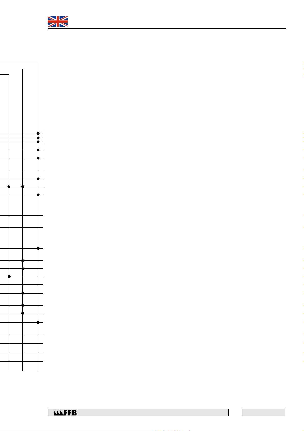
REMEDIAL MEASURES
A) Check and if necessary consult a competent person. To lower the platform without electrical power, refer to page opposite.
B) The electrical supply must be checked by a competent person.
C) If necessary, unload the platform and check that none of the cross-member ends are resting against the column base plates.
If necessary, adjust the nuts on the wire rope end fittings until the cross-member end is lifted, and then adjust the wire ropes.
D) Briefly raise the platform and then lower it again more slowly so as not to repeat this problem. Check and adjust its setting.
E) Check. If necessary, call F.F.B. Service Department for a replacement.
F) Check and remedy.
G) Examine each cross-member end. If the retaining system clearance and switch clearance are non-existent, lift the sensing roller so
that it no longer actuates the safety switch. Then, with it still up, operate the control knob towards RAISE, until the wire ropes are taut.
If the pump does not work, the breakdown is not due to this fault but to the next one (10). So as not to repeat this incident, adjust the
retaining system clearance and the switch clearance.
H) Raise the platform in order to release the latches from the ladder racks and check that they are working correctly. If necessary
check the control circuit and replace the faulty latch solenoid.
I) Check and identify the cross-member end that is not resting on its latch, then lift its sensing roller so that it no longer actuates the
safety switch. With it still elevated, operate the control knob towards RAISE until the obstruction can be removed or the sound of the
ladder rack dropping back can be heard (cam unlocking). If this incident is not due to an obstruction and happens frequently, check
the condition of the ladder rack, the squareness of the column and the adjustment of the cam.
J) Contact the F.F.B. Service Department.
K) Check the weight of the vehicle and if necessary, test with a lighter one.
L) Check in a clockwise direction watching the motor fan. If incorrect contact the F.F.B. Service Department.
M) Lower the platform back down and check the oil level. If this is not correct, top up with more oil.
N) Check and remedy the fault.
O) Check and remedy the fault.
P) This valve is factory set for replacement contact the F.F.B. Service Department.
Q) Check the pressure and the time taken to raise the platform: replace it if necessary.
R) Lower the platform or the auxiliary slightly.
NOTE: the auxiliary upper limit switch prevents the platform from being raised and vice versa.
S) Correctly position the three-way valve on the platform or auxiliary lift.
T) Adjust the photo cell or replace it. Re-adjust the level using the two-way valve.
U) Check its power supply. Lower the vehicle using the method to lower the auxiliary without electrical power.
V) Check the viscosity. Important this must be hydraulic oil 4 to 5 - Engler at 20° C.
Rue du Pré Neuf - 58440 MYENNES FRANCE
29
E 167 - GB - 6
Page 30
493 9021
493 9031
QUADRA
E 167 - GB - 6
30
Rue du Pré Neuf - 58440 MYENNES FRANCE
Page 31
493 9021
493 9031
QUADRA
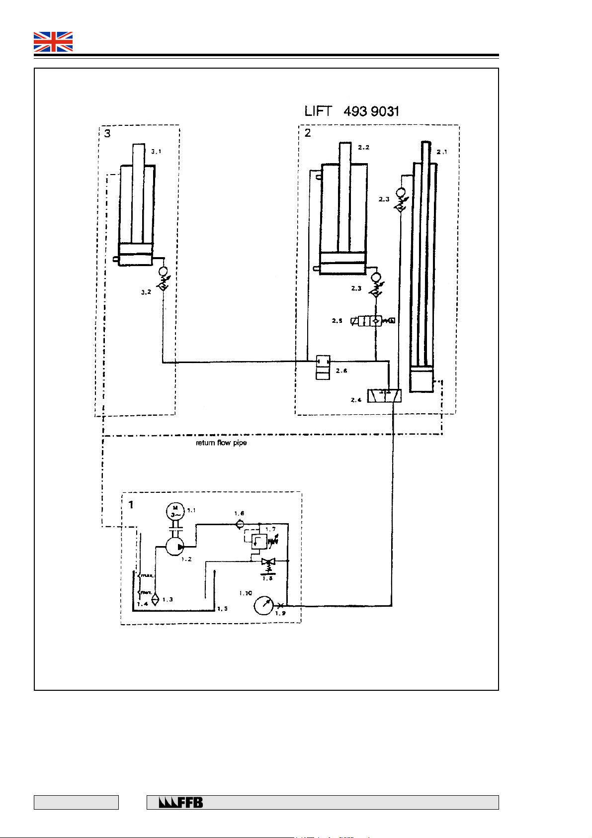
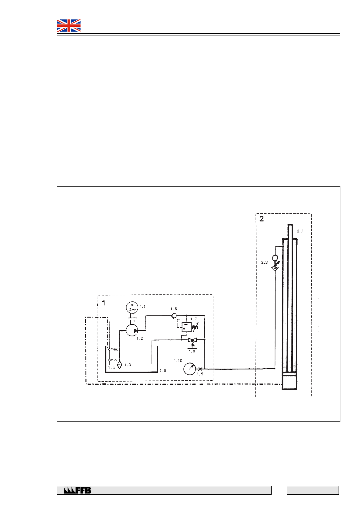
1. POWER PACK UNIT
1.1 Motor
1.2 Pump
1.3 Suction filter
1.4 Oil dipstick
1.5 Oil reservoir
1.6 Non-return valve
1.7 Pressure relief valve
1.8 ‘LOWER’ control
1.9 Gauge connector
1.10 Control gauge
LIFT 493 9021
2 - FIXED TRACK
2.1 Deck platform ram
2.2 Auxiliary emission ram
2.3 Safety valve - Hose failure
2.4 Three-way valve
2.5 Solenoid valve
2.6 Two-way valve
3. ADJUSTABLE TRACK
3.1 Auxiliary slave ram
3.2 Safety valve - pipework rupture
Rue du Pré Neuf - 58440 MYENNES FRANCE
31
E 167 - GB - 6
Page 32
493 9021
493 9031
QUADRA
E 167 - GB - 6
32
Rue du Pré Neuf - 58440 MYENNES FRANCE
Page 33
493 9021
493 9031
QUADRA
Rue du Pré Neuf - 58440 MYENNES FRANCE
33
E 167 - GB - 6
Page 34
493 9021
493 9031
QUADRA
E 167 - GB - 6
34
Rue du Pré Neuf - 58440 MYENNES FRANCE
Page 35
493 9021
493 9031
QUADRA
Rue du Pré Neuf - 58440 MYENNES FRANCE
35
E 167 - GB - 6
Page 36
493 9021
493 9031
QUADRA
TECHNICAL SPECIFICATION
Load capacity (platform) 3500 kg
Load capacity (auxiliary) 3000 kg
'Raise' time approx. 35 secs
'Lower' time 28 secs minimum
Hydraulic Circuit
Capacity 10 litres
Oil type hydraulic oil 256 8011
Engler viscosity at 20°C = 5
Max. working pressure 250 bar
Electrical Supply
Voltage 400 V 3 phase+earth (Can also be changed to 230V three phase)
Power 1.85 KW
Weight
493 9021 655 kg
493 9031 1015 kg
Weight of the Individual Component Parts
Description Weight (kg) Dimensions (mm)
Set of columns 150 2360 x 570 x 390
Set of cross-members 145 2800 x 350 x 320
Set of ramps 50 1040 x 450 x 130
Set of tracks :
493 9021 250 4400 x 440 x 250
493 9031 610 4400 x 520 x 470
Accessories 60 720 x 540 x 430
Maximum platform capacity 3500 kg
Minimum wheelbase 2.50 m
Minimum track 1.5 m
Load distribution 2/5 - 3/5
Equipment lifting strap capacity 1000 kg (minimum)
E 167 - GB - 6
36
Rue du Pré Neuf - 58440 MYENNES FRANCE
Page 37
493 9021
493 9031
QUADRA
ADD-ON STD Type 493 9021
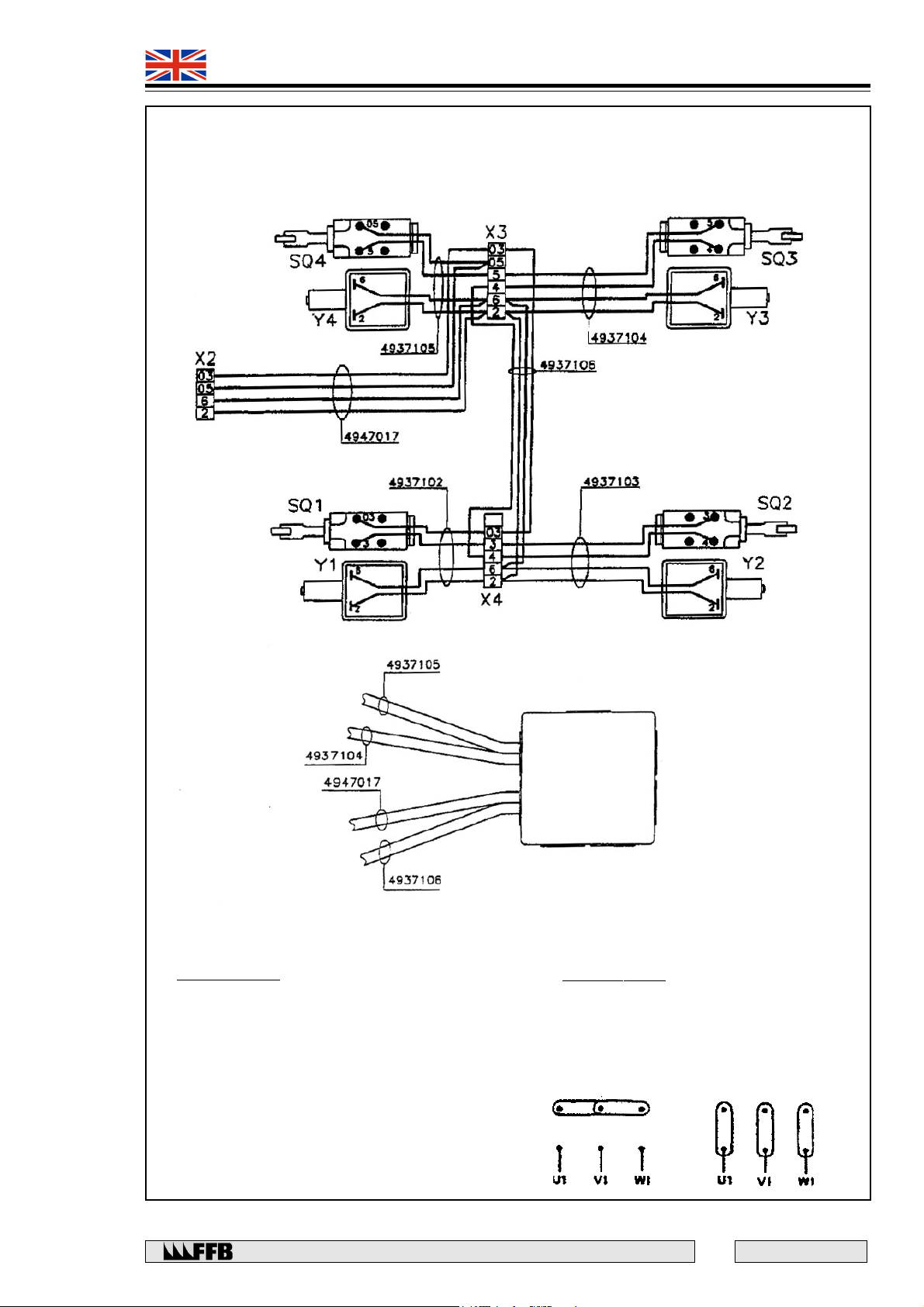
Wiring diagram
Post n° 4
(with motor)
Post n° 3
Post n° 1
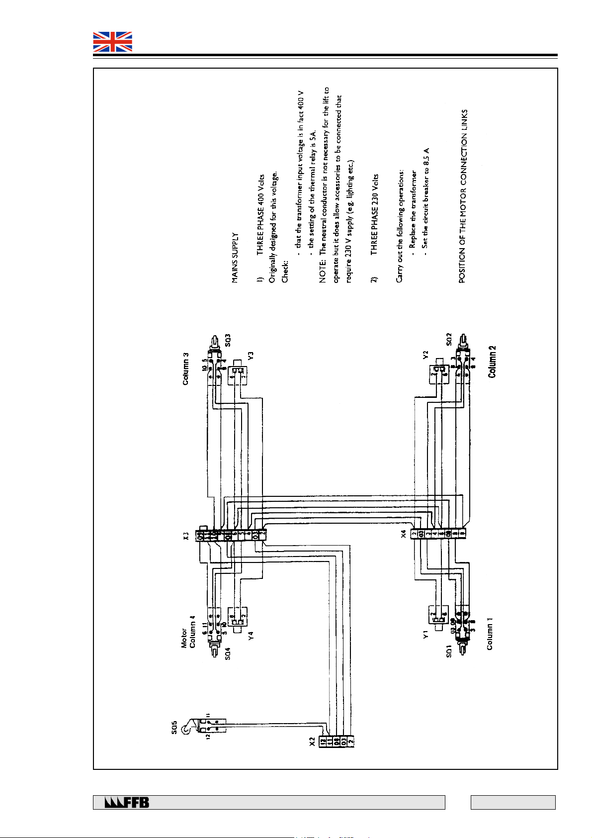
POWER SUPPLY :
1) 3 phases 400V :
- The lift can be directly wired.
- No modification required.
- Check the input voltage of the transformer which
must be 400V.
NOTA : The neutral wire is not necessary for the lift
itself. However, it is necessary for 230V accessories
(lighting kits, wheel alignement device, ...)
Post n° 2
2) 3 phases 230V :
- Make the following adjustments.
- Change the transformer.
- Change the position of the electric coupling
6 terminals of the motor as follow :
400 Volts 230 Volts
Rue du Pré Neuf - 58440 MYENNES FRANCE
37
E 167 - GB - 6
Page 38
493 9021
493 9031
QUADRA
ADD-ON STD Type 493 9021
Lift 493 9021
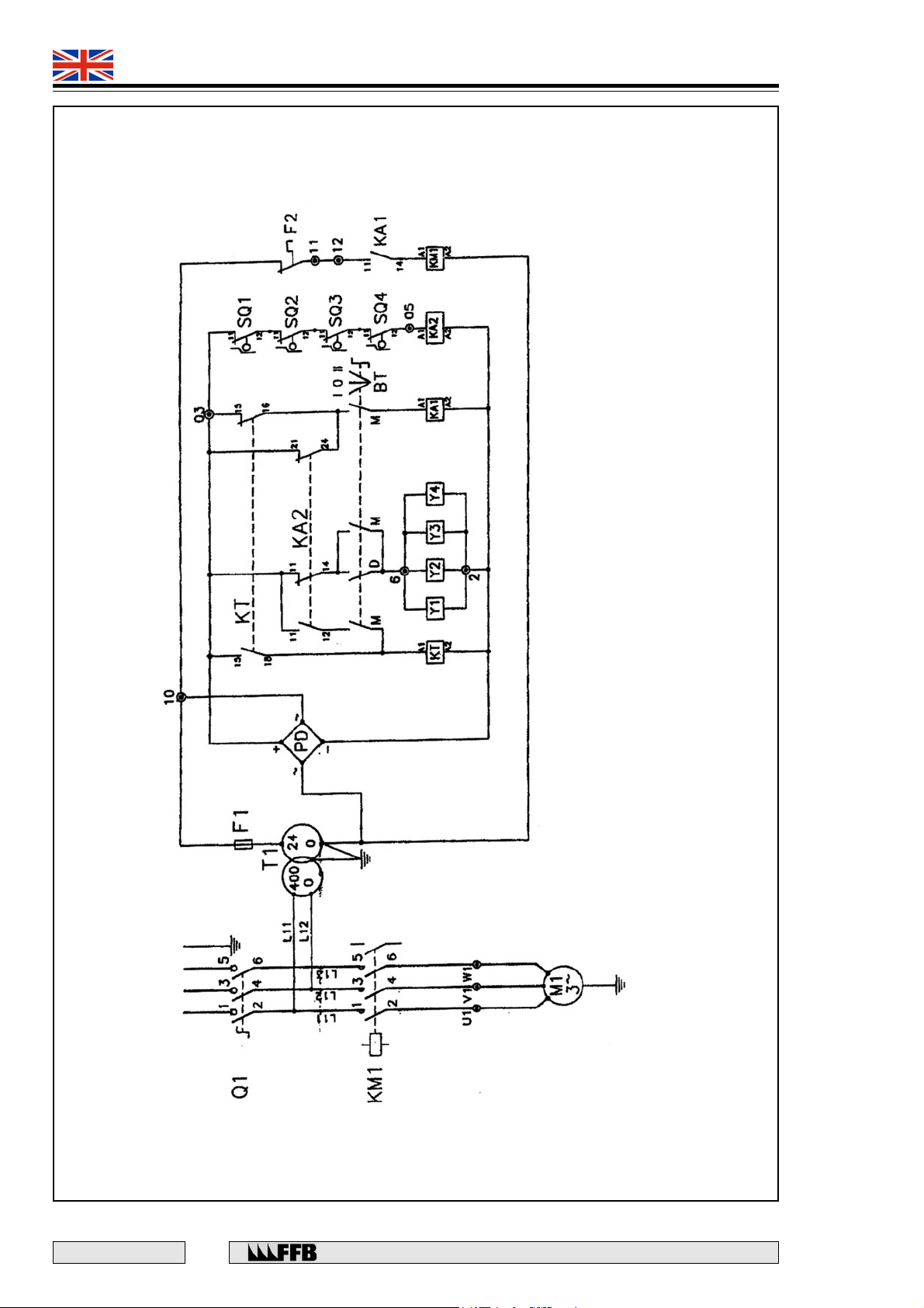
Electric wiring diagram
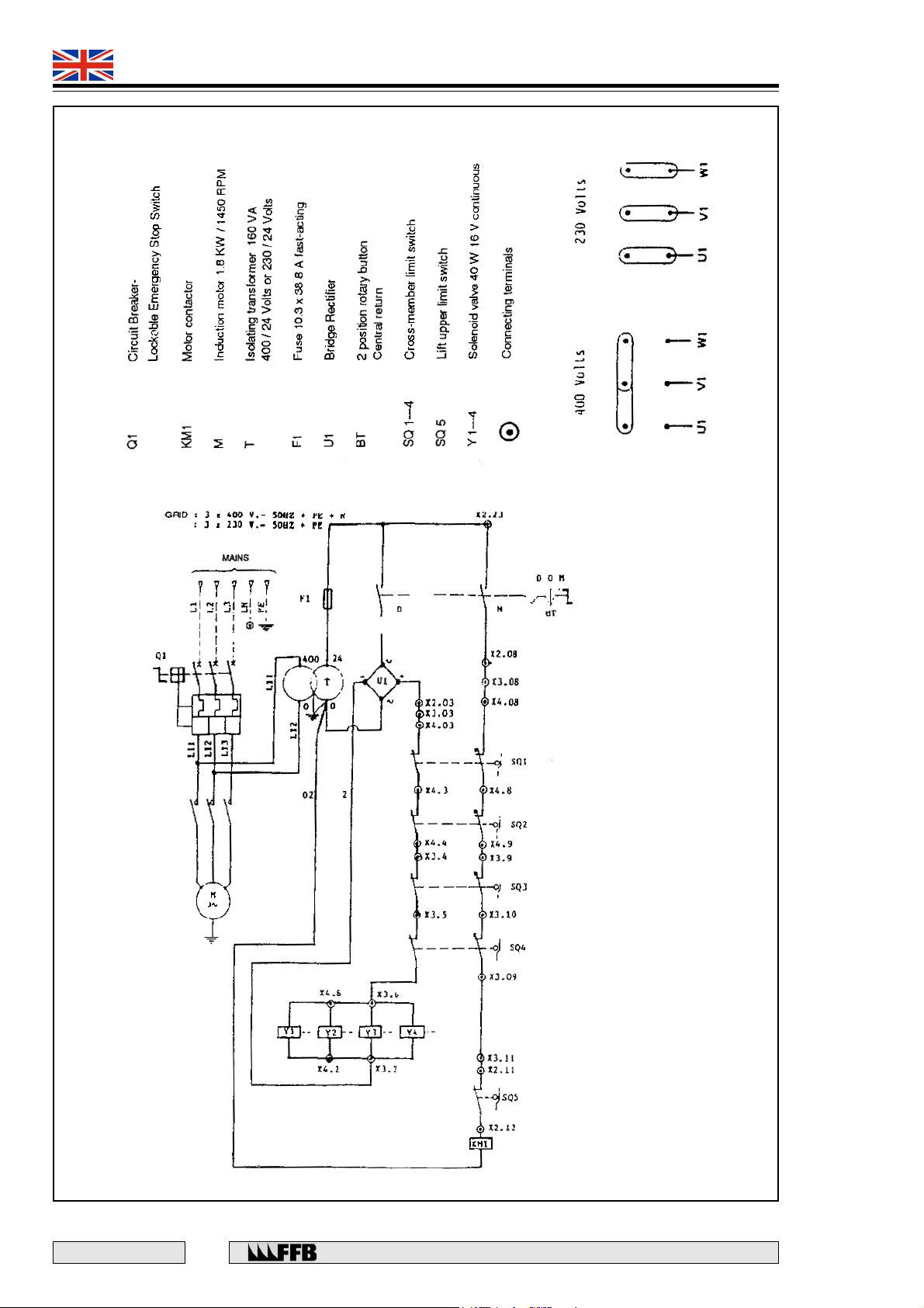
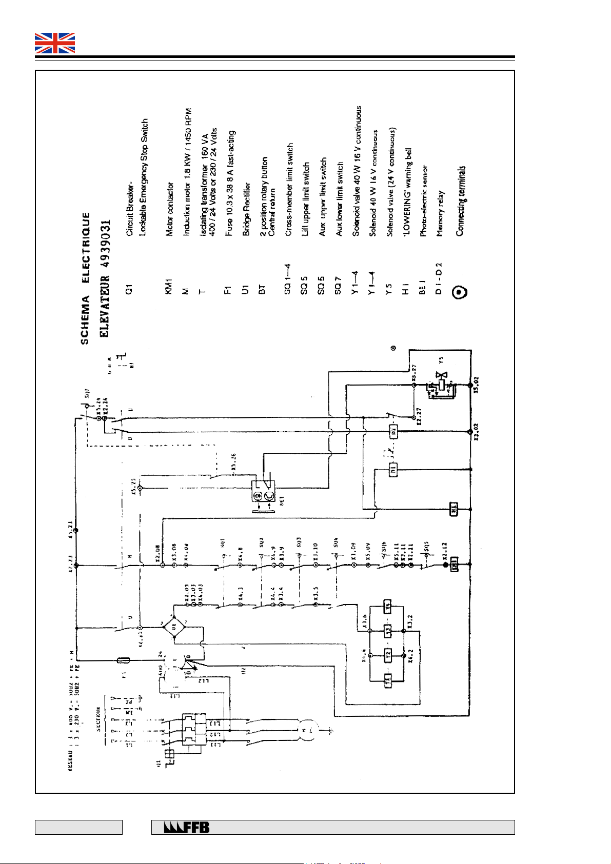
KT : Timing relay 3 sec. (switch-on delayed)
Y1...Y4 : Electric solenoid 40W 16V (direct current)
SQ1...SQ4 : Cable break / loosening detector switch
KA1 : Auxiliary relay 24V d.c. (ascent)
KA2 : Cable break detectors relay 24V- d.c.-2 reversers
(automatic return to "O")
Q1 : 3 phase main switch
KM1 : 3 phase motor switch
M1 : Motor 1,8 Kw / 2850 rpm
T1 : Transformer 400V / 24V - 160 VA
F1 : Fuse 10A Am (slow)
PD : Diode bridge
BT : Ascent/ Descent Button
F2 : Motor overheating safety switch (Qty : 2)
E 167 - GB - 6
Power supply 400V
as required by laws in force
38
Rue du Pré Neuf - 58440 MYENNES FRANCE
Page 39
493 9021
493 9031
QUADRA
ADD-ON STD Type 493 9021
Rue du Pré Neuf - 58440 MYENNES FRANCE
39
E 167 - GB - 6
Page 40
493 9021
493 9031
QUADRA
ADD-ON STD Type 493 9021
E 167 - GB - 6
40
Rue du Pré Neuf - 58440 MYENNES FRANCE
Page 41
493 9021
493 9031
QUADRA
ADD-ON STD Type 493 9021
Rue du Pré Neuf - 58440 MYENNES FRANCE
41
E 167 - GB - 6
Page 42
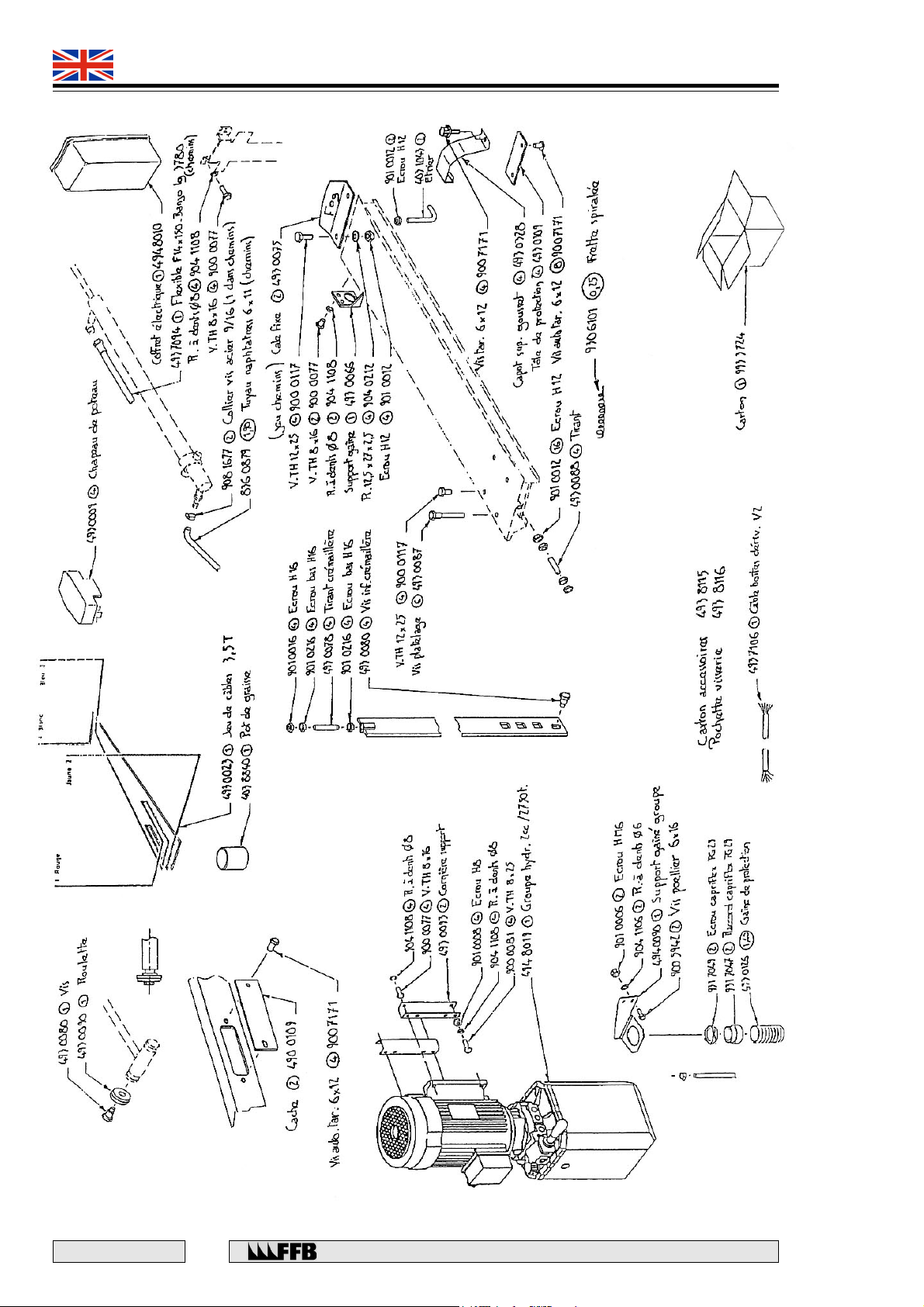
493 9021
493 9031
QUADRA
ADD-ON STD Type 493 9021
E 167 - GB - 6
42
Rue du Pré Neuf - 58440 MYENNES FRANCE
Page 43
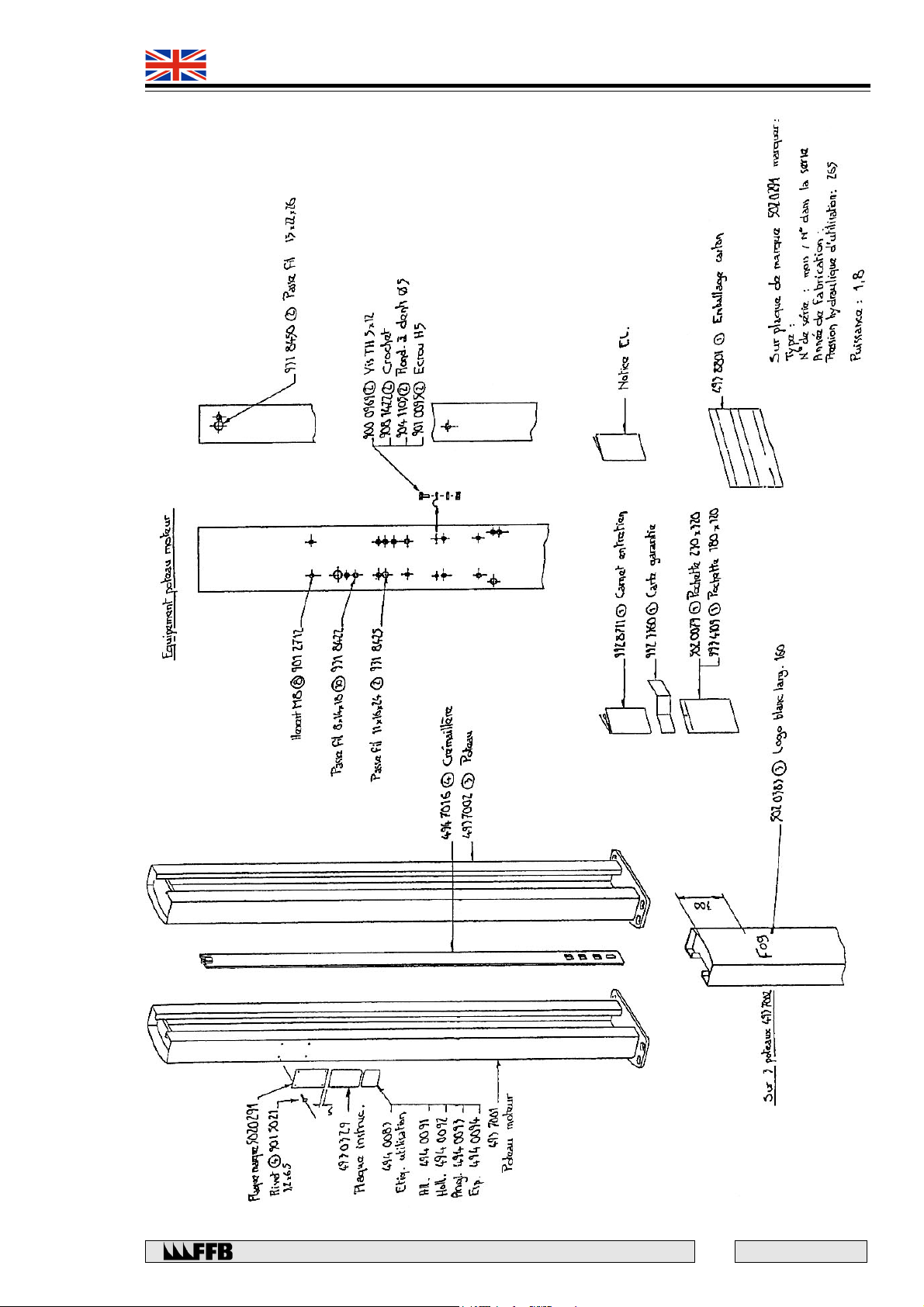
493 9021
493 9031
QUADRA
ADD-ON STD Type 493 9021
Rue du Pré Neuf - 58440 MYENNES FRANCE
43
E 167 - GB - 6
Page 44
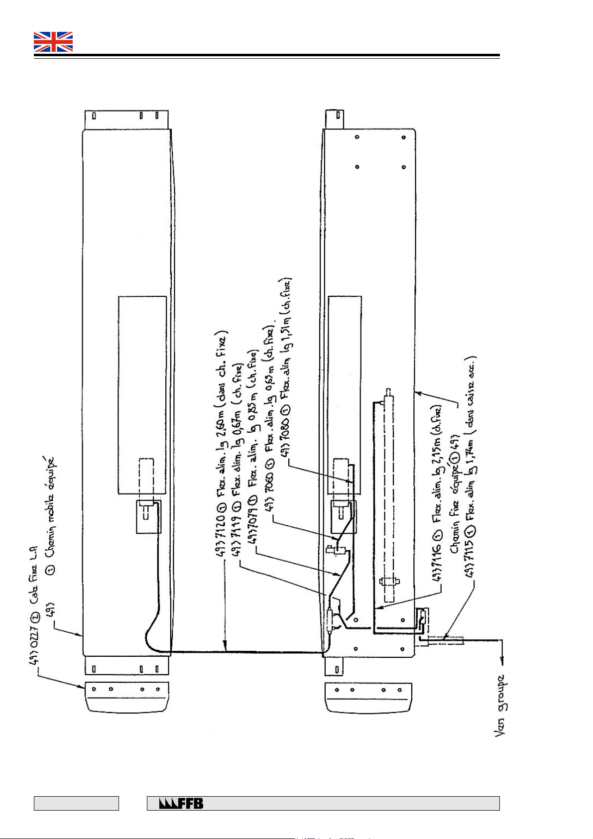
493 9021
493 9031
QUADRA
ADD-ON Aux. Type 493 9031
E 167 - GB - 6
44
Rue du Pré Neuf - 58440 MYENNES FRANCE
Page 45
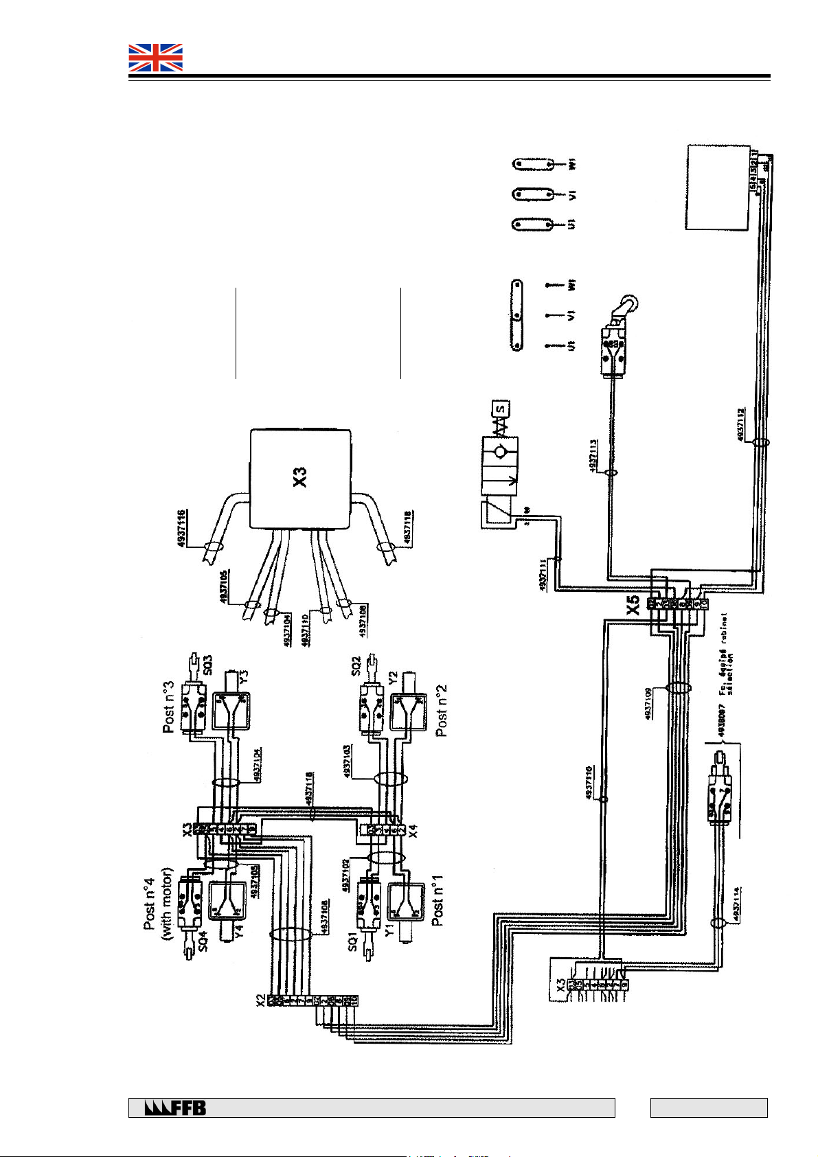
493 9021
493 9031
QUADRA
ADD-ON Aux. Type 493 9031
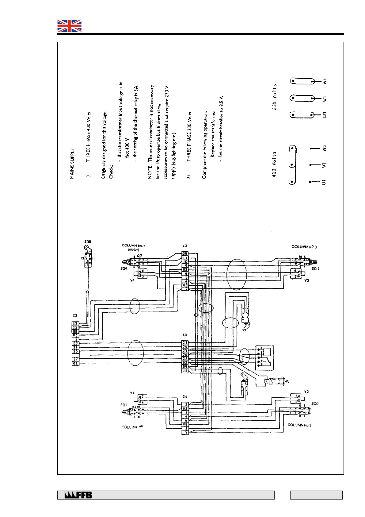
230 Volts
400 Volts
POWER SUPPLY :
3 phases 400V :
1)
- The lift can be directly wired.
- No modification required.
- Check the input voltage of the transformer
which must be 400V.
NOTA : The neutral wire is not necessary
for the lift itself. However, it is necessary
for 230V accessories (lighting kits,
3 phases 230V :
wheel alignement device, ...)
2)
Wiring diagram 493 9031
- Make the following adjustments.
- Change the transformer.
- Change the position of the electric
coupling 6 terminals of the motor as follow :
Rue du Pré Neuf - 58440 MYENNES FRANCE
45
E 167 - GB - 6
Page 46
493 9021
493 9031
QUADRA
ADD-ON Aux. Type 493 9031
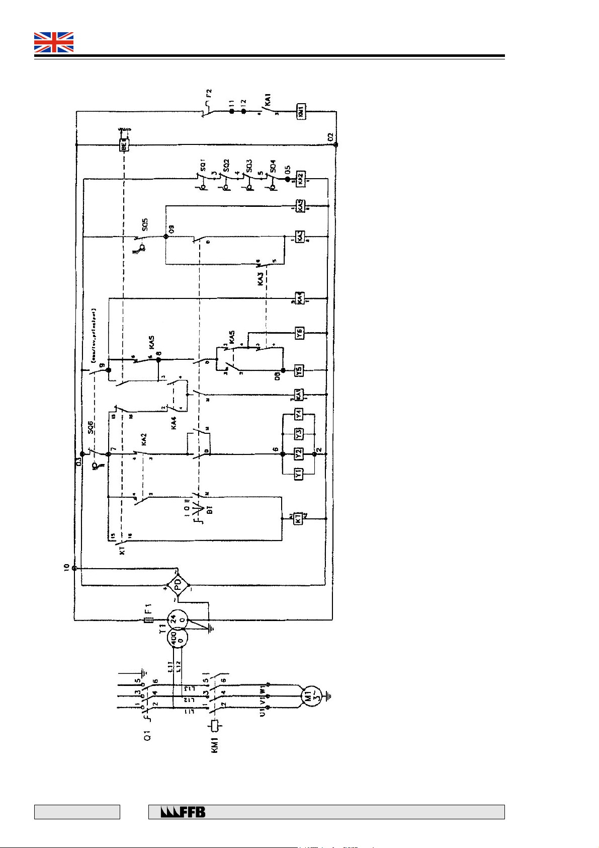
Wiring diagram lift 493 9031
Y1...Y4 : Solenoid magnet 40W - 16V d.c.
Y5 : Solenoid valve oil for lowering wheel free lift 24V d.c.
Y6 : Sounder 24V d.c.
SQ1...SQ4 : Cable break / loosening detector switch 1NF (normaly closed)
SQ5 : Bottom limit detector (auxiliary lift) 1NO (normaly open)
SQ6 : Selection main (auxiliary lift) detector 1NF - 1NO
BE1 : Photocell 1 reverser (adjustment L-ON)
Ascent : 1NO - Descent : 2NO / 1NF
E 167 - GB - 6
Power supply 400V
as required by laws in force
46
Rue du Pré Neuf - 58440 MYENNES FRANCE
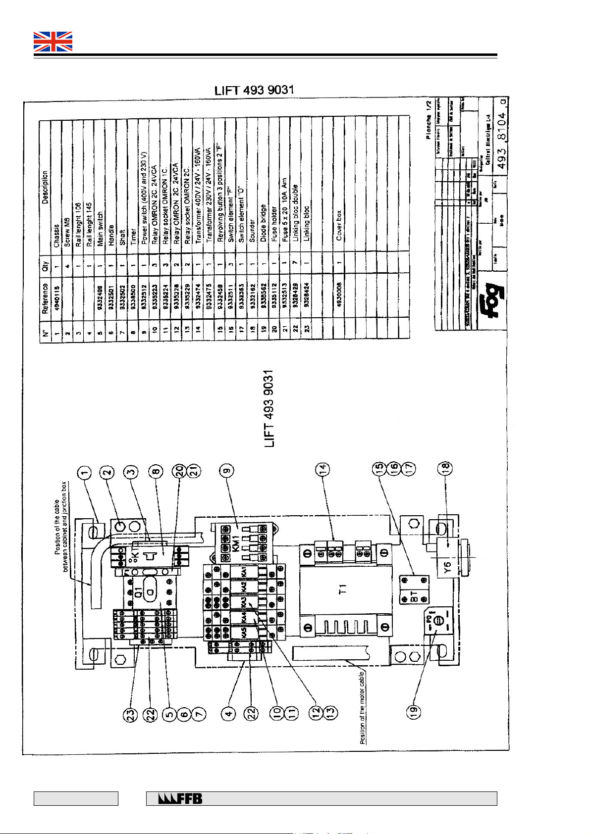
Q1 : 3-ways main switch
KM1 : 3-ways motor switch 24V a.c.
M1 : Motor 1,8 Kw 2850 rpm
T1 : Transformer 400V / 24V - 160 VA
F1 : Fuse 10A Am (slow)
PD : Diode bridge 10A
BT : Ascent/ Descent Button (automatic return to "O")
F2 : Motor overheating switch (Qty : 2)
KT : Timing relay 3 sec. (switch-on delayed)
KA1 : Auxiliary relay ascent 24V d.c. - reverser
KA2 : Auxiliary relay (cable break) 24V d.c. - reverser
KA3 : Auxiliary relay (upholding) 24V d.c. - 2 reversers
KA4 : Auxiliary relay (selection) 24V d.c. - 1 reverser
KA5 : Auxiliary relay (bottom limit switch) 24V d.c. - 2 reversers
Page 47
493 9021
493 9031
QUADRA
ADD-ON Aux. Type 493 9031
Rue du Pré Neuf - 58440 MYENNES FRANCE
47
E 167 - GB - 6
Page 48
493 9021
493 9031
QUADRA
ADD-ON Aux. Type 493 9031
E 167 - GB - 6
48
Rue du Pré Neuf - 58440 MYENNES FRANCE
Page 49
493 9021
493 9031
QUADRA
ADD-ON Aux. Type 493 9031
Rue du Pré Neuf - 58440 MYENNES FRANCE
49
E 167 - GB - 6
Page 50
493 9021
493 9031
QUADRA
ADD-ON Aux. Type 493 9031
E 167 - GB - 6
50
Rue du Pré Neuf - 58440 MYENNES FRANCE
Page 51
493 9021
493 9031
QUADRA
ADD-ON Aux. Type 493 9031
Rue du Pré Neuf - 58440 MYENNES FRANCE
51
E 167 - GB - 6
Page 52
493 9021
493 9031
QUADRA
ADD-ON Aux. Type 493 9031
E 167 - GB - 6
52
Rue du Pré Neuf - 58440 MYENNES FRANCE
Page 53
493 9021
493 9031
QUADRA
ADD-ON Aux. Type 493 9031
Rue du Pré Neuf - 58440 MYENNES FRANCE
53
E 167 - GB - 6
Page 54
493 9021
493 9031
QUADRA
ADD-ON Aux. Type 493 9031
E 167 - GB - 6
54
Rue du Pré Neuf - 58440 MYENNES FRANCE
Page 55
493 9021
493 9031
QUADRA
Rue du Pré Neuf - 58440 MYENNES FRANCE
55
E 167 - GB - 6
Page 56
493 9021
493 9031
QUADRA
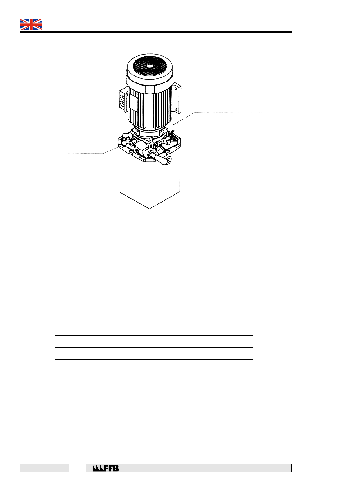
Adjustment of the flow control valve (Power unit HPI)
Flow control valve
(located on the back side)
Pressure
gauge outlet
To adjust the flow control valve, proceed as follows :
- Remove the cap.
- Remove the cap nut.
- Release the lock nut.
- Operate the adjusting screw (6 mm hexagon key), see table.
- Adjust with pressure gauge: raise the lift at the top limit stop and operate
the screw to modify the pressure.
NOTA : To increase the pressure turn the screw clockwise (CW).
After test, reset the initial adjustment.
Initial
adjustment
Adjustment for
dynamic test
Lift 3T STD 265 bars 285 bars
Lift 3T (Aux.) 290 bars 310 bars
Lift 3,5T STD 265 bars 285 bars
Lift 3,5T (Aux.) 290 bars 310 bars
Lift 4T 245 bars 265 bars
Lift 5T 240 bars 270 bars
NOTA : The power unit is delivered for an initial adjustment of 245 bars.
IMPORTANT : Put a new cap after each intervention on the flow control valve
(Ref. : 942 0081).
E 167 - GB - 6
56
Rue du Pré Neuf - 58440 MYENNES FRANCE
Page 57
493 9021
493 9031
QUADRA
Guarantee
F.F.B. CONTRACT GUARANTEE
Your F.F.B. equipment is guaranteed against any operating defects resulting from material or design faults
under the following conditions:
The operating defect must appear within a period of one year from when the equipment specified in the
order is first made available for use. The guarantee is excluded if the material or design fault is the
purchaser’s responsibility or if the operating defect results from work carried out on the equipment without
our authorisation. The same applies if any of the components used by the purchaser are not original F.F.B.
spares, if the operating defect stems from normal wear and tear on the equipment or from negligent or
insufficient maintenance or stocking on the part of the purchaser, if the operating defect results from poor
installation or if the operating defect is the result of a
control.
Under the guarantee, we will replace or repair, free of charge, the items or materials identified by our
technical department as being faulty. Any parts or accessories obtained from external sources and
bearing a proper brandname, are included under our guarantee only to the same extent as the
guarantee given by the suppliers of these items.
The repair, modification or replacement of any parts or equipment during the guarantee period cannot
result in the length of the guarantee being extended.
If, under the terms of the guarantee, the equipment must be returned to F.F.B., it must be suitably
packaged. The application of the guarantee cannot, under any circumstances, give rise to damages or
interest being claimed. The F.F.B. contract guarantee is in addition to the statutory guarantee against
hidden defects provided under current legislation.
force majeure
or any other occurrence outside of our
For any claims made under the terms of the F.F.B. guarantee, the guarantee slip duly completed by your
distributor will be required, or failing that, proof of purchase of the equipment concerned.
GUARANTEE
REF N°
DATE OF PURCHASE
PURCHASED BY
SOLD BY
SERIAL N°
GUARANTEE
REF N°
DATE OF PURCHASE
PURCHASED BY
SOLD BY
SERIAL N°
Distributor’s stamp
PART TO BE RETAINED
Rue du Pré Neuf - 58440 MYENNES FRANCE
COUPON TO BE RETURNED WITHIN 15 DAYS TO :
Distributor’s stamp
Export Department
58440 MYENNES - FRANCE
F.F.B.
Rue du Pré Neuf
57
E 167 - GB - 6
Page 58

493 9021
493 9031
QUADRA
E 167 - GB - 6
58
Rue du Pré Neuf - 58440 MYENNES FRANCE
Page 59

493 9021
493 9031
QUADRA
DECLARATION DE CONFORMITE
EC Declaration of conformity
EG-Konformitätserklärung
F.F.B.
S.A.
Rue du Pré-Neuf
58440 Myennes (France)
Tel. 03 86 39 50 50
Fax 03 86 39 50 60
dé clare e n a pplication de la directive 89/392/CEE modifiée e n dernie r lie u par la directive 98/37/CEE
que la machine décrite :
declares according to the 89/392/EEC Direc tive lastly amended by 98/37/EEC Direc tive that the machinery
describ ed :
erk lärt gemäss der Richtlinie 89/392/EWG, geändert durch Richtlinie 98/37/EW G an letzter Stelle, dass der
beschriebene Apparat :
ELEVATEUR à 4 COLONNES à prise sous roues, électrohydraulique
Four post lif t, electrohydraulical,
Vier-Saülen Hebebühne, elek trohydraulisch
Identifica ti on comme rcia le : QUADRA
Commercial name, Geschäftsname
Capacité :
Capacity, Tragfähigk eit
Type :
Typ
4939001A-4939002A-4939003A-4939004A-4939005A-4939011A-4939012A-4939013A-4939014A
4939015-4939021-4939022-4939023-4939024-4939025-4939031-4939032-4939033-4939034-4939035
4939036-4939037-4939038-4939039
3,5 tonnes
493 90 - -
Numéro de série :
Serial numb er, Fabrik -Nr
est conforme à l'exemplaire qui a reçu l'attestation d'examen de type numéro :
délivrée par :
U T A C
Union Te chnique de l'Automobile , du Motocycle e t du Cycle
Autodrome de Linas - Montlhé ry
91310 Monthléry (France)
conforms to the machinery example of t he EC Type examination Certific ate number :
which has been issued b y UTAC.
übereinstimmt mit derjenigen Maschine für die eine EG Typ Abnahmeb escheinigung Nr :
durch UTAC durchgeführt wurde.
Date :
Date, Datum
31 juillet 2001
Olivier GAC
Responsable Qualité
69.150X.0061.03.00
69.150X.0061.03.00
69.150X.0061.03.00
Rue du Pré Neuf - 58440 MYENNES FRANCE
59
E 167 - GB - 6
Page 60
 Loading...