

Page 1

User Guide
FFFA001523-01
www.focusrite.com
Page 2

CONTENTS
About this User Guide .........................................................3
Box Contents ................................................................3
INTRODUCTION ................................................................4
INSTALLATION GUIDE ...........................................................5
RedNet X2P Connections and Features...........................................5
Top Panel ..............................................................5
LCD Display ............................................................7
Rear Panel .............................................................9
Physical Characteristics ......................................................10
Power Requirements.........................................................10
REDNET X2P OPERATION .......................................................11
First Use and Firmware Updates ...............................................11
Digital Clocking .............................................................11
Pull Up and Pull Down Operation...............................................11
Front Panel Lockout .........................................................12
OTHER REDNET SYSTEM COMPONENTS ..........................................13
REDNET CONTROL 2 ...........................................................13
ID (Identification) ............................................................13
Reverse ID .................................................................13
Tools Menu .................................................................14
APPENDICES .................................................................16
1 – Connector Pinouts........................................................16
Ethernet Connectors (Dante) .............................................16
XLR Connectors ........................................................16
1/4” Jack Connector ....................................................16
2 – Air information...........................................................17
PERFORMANCE AND SPECIFICATIONS............................................ 18
Focusrite RedNet Warranty and Service .........................................21
Registering Your Product .....................................................21
Customer Support and Unit Servicing ...........................................21
Troubleshooting ............................................................21
2
Page 3

About this User Guide
This user guide applies to the RedNet X2P Dante interface and mic preamp with stereo line &
headphone monitoring. It provides information about installing and using the unit, and how it can be
connected into your system.
A RedNet System User Guide is also available from the RedNet product pages of the Focusrite
website. The guide provides a detailed explanation of the RedNet system concept, that will help you
achieve a thorough understanding of its capabilities. We recommend that all users, including those
already experienced in digital audio networking, take the time to read through the System User
Guide so that they are fully aware of all the possibilities that RedNet and its software have to offer.
Should either User Guide not provide the information you need, be sure to consult:
https://pro.focusrite.com/technical-support, which contains a comprehensive collection of common
technical support queries.
Dante® and Audinate® are registered trademark of Audinate Pty Ltd.
Box Contents
• RedNet X2P unit
• Ethernet cable
• Locking DC power supply
• Safety information cut sheet
• RedNet Getting Started Guide
• Product Registration Card – please follow the instructions on the card as it provides links to:
RedNet Control
RedNet PCIe drivers (included with RedNet Control download)
Audinate Dante Controller (installed with RedNet Control)
Dante Virtual Soundcard (DVS) Token and download instructions
3
Page 4

INTRODUCTION
Thank you for purchasing the Focusrite RedNet X2P.
RedNet X2P incorporates two local Red Evolution mic/line/instrument preamp channels, plus two
channels of premium D-A conversion for Dante audio-over-IP signals, to provide a stereo monitoring
unit, featuring separate headphone and line outputs.
Local analogue input is via two Combo connectors on the rear panel, providing Mic/Line input on
balanced XLR, or instrument input on standard 1/4” jack. Separate controls for gain, +48V phantom
power, polarity inversion, high-pass filter and Air mode, plus a control for the Network/Local Mix,
are included on the front panel. The input encoders can function independently or be linked together,
and the channels are sent to the outputs as either stereo or mono-summed.
RedNet X2P includes two line-output XLRs plus a stereo TRS 1/4” jack socket. It provides highquality digital to analogue conversion for accurate monitoring on loudspeakers or headphones and
is designed to drive high or low impedance headphones at high levels with significant audio output
power. Separate volume control knobs are provided for Headphone and Line output levels, the latter
featuring buttons for mute and Input Mix, with associated LEDs.
An LCD display on the front panel provides: status information about the device and preamp controls,
level metering plus network flags and lock information.
The compact unit, mounted in an enclosure based around a sturdy road-worthy aluminium extrusion,
is fitted with non-slip feet and can either sit securely on a flat surface or be mounted on top of a mic
stand using the 3/8” BSW threaded bush incorporated in the base.
Dual locking etherCON connectors are included on the rear-panel to connect to the network and to
daisy-chain to additional network devices.
The unit is powered via Power over Ethernet (PoE) or via the locking rear-panel barrel connector and
included DC power supply. Each PSU’s status can be monitored remotely over the network and on
the LCD display.
Tailored for all environments, each unit features two network ports, PoE and DC power options,
rugged construction with latching connectors, remote control and remote monitoring – RedNet X2P
is the perfect portable break-out solution for analogue monitoring from a Dante network.
4
Page 5

INSTALLATION GUIDE
RedNet X2P Connections and Features
Top Panel
4
3
6
1
2
5
1. Headphone Level Pot
Controls the volume level sent to the stereo headphone jack.
2. Local Input Gain Encoders
Independent gain controls for the Local inputs on Combo connectors 1 and 2.
Either encoder’s control can be applied to both channels using the LINK function; see next page.
3. Local Input Function Switches
Two sets of function switches for Local Inputs 1 and 2:
• 48V – Enables 48V phantom power on the XLR input.
• Ø (Phase) – Enables phase reverse
• HPF – Enables 80Hz high pass filter
• AIR – Changes the input characteristics to Air mode. See page 17 for further information
7
8
9
4. Input Mix Pot
Adjusts the level balance between the Network and the Local input signals. The mix signal
can be smoothly varied between fully Network and fully Local using the pot. This mix signal is
always sent to the headphone socket.
5. Headphone Socket
Standard 1/4” stereo jack for headphones.
6. Line Output Level Pot
Controls the volume level sent to the Line Output XLRs.
5
Page 6

Top Panel . . . Continued
7. Input Mix Switch
Press to send the combined Network/Local mix signal to the Line Output XLRs. When not
active the Line Outputs will receive the Network signal only.
7
8
9
Press-and-hold for 1.5 seconds to display the Line/Headphone output signals on the LCD
display’s level meters. The signals will be visible while the switch remains pressed.
8. Mute Switch
Press to mute the Line output XLRs. Power-up state is congurable from the Tools menu.
Press and hold for 1.5 seconds to activate the Reverse ID function which will highlight the
device in RedNet Control. Reverse ID will be active while the switch remains pressed.
9. Link Switch
Press to combine the Local Input Gain encoders so they affect both channels. When Link is
active, changing the level of either encoder will alter both channels by the same amount. Any
existing offset between the two channels will be maintained.
Note that the action of the link switch will be modied if the “Auto” option is selected from the Tools menu. In
this mode, the Line and Headphone outputs will switch between Stereo (Link on), and Mono-Summed (Link
off) – where each Local input becomes a mono source feeding both the Left & Right outputs.
Press-and-hold for 1.5 seconds to activate Front Panel Lockout. See page 12 for full description
of Lockout options.
6
Page 7
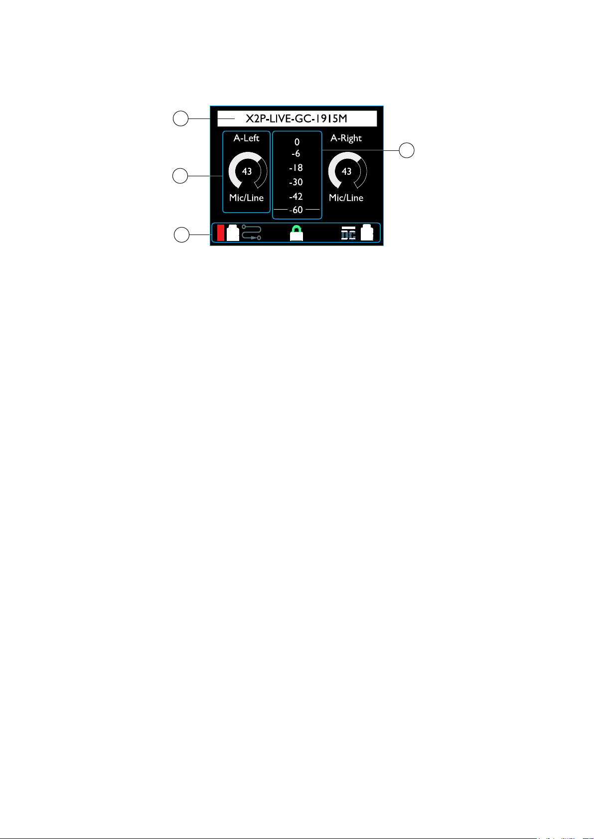
LCD Display
1. Status Bar
Shows the name of the device as given in RedNet Control or Dante Controller – updated
automatically. Names longer than the display will be truncated with “…”
The display will also show confirmation of any lock actions. Messages will be displayed for 3
seconds before returning to the device name:
1
3
2
4
• “Preamps Locked” – Appears when the preamp controls are locked on the device
• “Line Output Locked” – Appears when Line outputs are locked on the device
• “Preamps/Line Out Locked” – Appears when both options are locked on the device
2. Preamp Control & Status
Shows the following information for both Local input preamp channels:
• Channel name – Live update from RedNet Control or Dante Controller
• Gain control icon – Shows level control position and gain value, 0–68dB in 1dB steps
• Input type – Mic / Line or Instrument
3. Level Meter
Shows signal level, after gain control and input function, for preamp inputs 1 and 2. LED
colours represent the following signal levels in dBFS:
Red: 0dB
Yellow: -6dB
Green: -18dB
Green: -30dB
Green: -42dB
Green: -60dB
7
Page 8

LCD Display . . . Continued
4. Status Icons
Each icon can be off (black) or illuminated as follows:
Dante signal level in dB:
4
Red: 0dB
Yellow: -6dB
Green: -42dB
Black: <-42dB
Locked – Illuminates if unit is successfully locked to the network
Preamp Lock – Illuminates if any of the lock states is active. The icon will flash if locked
controls are modified. See page 12 for full description of Lock functions
DC power input – Illuminates if power is being received from the external DC supply
PoE power input – Illuminates if DC power is being received via the Ethernet cable
Device routing:
Two receive channels are routed
One receive channel is routed
No receive channels are routed
8
Page 9

Rear Panel
13 4 52
1. Network Port 1 / Primary Power Input*
RJ45 [etherCON] connector for the Dante network. Use standard Cat 5e or Cat 6 network
cables to connect RedNet X2P to an Ethernet network switch.
Power over Ethernet (PoE) can be used to power the RedNet X2P. Connect an appropriately
powered Ethernet cable to network port 1.
2. Network Port 2
Second RJ45 [etherCON] network port which can be used to daisy-chain additional devices.
This port does not accept PoE input and does not pass power out.
This port cannot be used as the secondary connection on redundant networks – network ports 1 and 2 always
function as a 2-port switch.
3. Secondary Power Input*
DC input with locking connector for use where Power-over-Ethernet (PoE) is not available.
Can be used in conjunction with PoE.
When both power supplies are available PoE will be the default supply.
4. Line Out XLRs
Two balanced output channels which can, for example, be used for monitor loudspeakers.
(Passive speakers will require external amplification). Software selectable +18 / +24 dBu
maximum output level.
5. Local Analogue inputs
Combo connectors for Local Mic/Line or Instrument inputs. Balanced XLR for Mic/Line
sources, mono TS jack for instrument input; automatic detection of input type. +48V phantom
power will be disabled when a 1/4” TS jack is inserted.
*For health and safety reasons, do not power-up RedNet X2P while monitoring through headphones.
Refer to the Appendix on page 16 for the connector pinouts.
9
Page 10

Physical Characteristics
140mm / 5.5”
47.5mm / 1.9”
104mm / 4.1”
RedNet X2P dimensions are illustrated in the diagram above.
RedNet X2P weighs 1.04 kg and is equipped with rubber feet for desktop mounting. The baseplate
includes a female 3/8” BSW thread so the unit can be mounted on a microphone stand.
A Kensington Lock slot is located in the left side panel allowing a user to secure the device.
RedNet X2P generates little significant heat and is cooled by natural convection.
Note. The maximum operating environmental temperature is 45°C / 113°F.
Power Requirements
RedNet X2P can be powered from two separate sources: Power-over-Ethernet (PoE) or DC input via
external mains supply.
Standard PoE requirements are: 37.0–57.0 V @ 1–2 A (approx.) – as supplied by many suitably equipped
switches and external PoE injectors. Note that PoE can only be accepted at Network Port 1 and that
power is not transmitted as an output on Network Port 2.
PoE injectors used should be Gigabit capable.
To use the 12V DC input, connect the external plugtop PSU supplied to an adjacent mains outlet.
Only use the DC PSU supplied with RedNet X2P. Use of other external supplies may affect performance or could
damage the unit.
When both PoE and external DC supplies are connected, PoE becomes the default supply.
The power consumption of the RedNet X2P is: DC supply: 13.32 W, PoE: 11.0 W
Please note that there are no fuses in RedNet X2P, or other user-replaceable components of any
type. Please refer all servicing issues to the Customer Support Team (see “Customer Support and
Unit Servicing” on page 21).
10
Page 11

REDNET X2P OPERATION
First Use and Firmware Updates
Your RedNet X2P may require a firmware update* when it is first installed and switched on. Firmware
updates are initiated and handled automatically by the RedNet Control application.
*It is important that the rmware update procedure is not interrupted – either by switching off power to the
RedNet X2P or the computer on which RedNet Control is running, or by disconnecting either from the network.
From time to time Focusrite will release RedNet firmware updates within new versions of RedNet
Control. We recommend keeping all RedNet units up to date with the latest firmware version supplied
with each new version of RedNet Control.
The RedNet Control application will automatically inform the user if there is a rmware update available.
Digital Clocking
Each RedNet X2P will automatically lock to a valid Network Master via its Dante connection.
Alternatively, if a Network Master is not already present, the unit can be chosen as the Network
Master by the user.
Pull Up and Pull Down Operation
RedNet X2P is able to operate at a specified pull up or pull down percentage as selected in the Dante
Controller application (Dante Ultimo capability):
• 44.1 kHz
• 48 kHz
• 88.2 kHz
• 96 kHz
• Pull Up/Down:
° -4%
° -0.1%
° 0%
° +0.1%
° +4.1667%
11
Page 12

Operation . . . Continued
Front Panel Lockout
The front panel controls can be locked to prevent accidental modification; three lockout modes are
available: ‘Preamp Control ’, ‘Line Out Control’ and both modes together. Note that when Lockout
is active, only the front panel controls are disabled – control changes over the network will still be
possible.
Lockout can be activated and deactivated from the Tools menu, or by pressing the front panel LINK
switch for more than 1.5 seconds. The lockout mode is selected using the Tools menu. See page 14.
Preamp Control – The following controls will be disabled:
• Input Level encoders
• +48V
• Phase
• HPF
• AIR
• Link – This does not disable Front Panel Lockout (>1.5s)
Line Out Control – The following controls will be disabled:
• Line Output Level pot
• Network/Local Mix pot – Headphone levels can still be adjusted
• Mute – This does not disable Reverse ID (>1.5s)
• Input Mix
Notes:
- If level pots are moved whilst Line Out Control Lockout is active, the pot will need to be returned to its pre-lockout
position before new level changes will take effect. (This prevents sudden jumps in output level.)
- Front Panel Lockout will continue after a reboot and/or power-cycle.
- If a user tries to control a locked switch on the Front Panel, the ‘‘Locked” icon on the LCD will ash 5 times.
- If a user tries to control a locked pot on the Front Panel, the ‘‘Locked” icon on the LCD will ash whilst the control is
adjusted and for approximately 2.5s afterwards.
12
Page 13

OTHER REDNET SYSTEM COMPONENTS
The RedNet hardware range includes various types of I/O interface and the PCIe/ PCIeR digital audio
interface cards which are installed in the system’s host computer or in a chassis. All the I/O units
can be considered as “Break-Out” (and/or “Break-In”) boxes to/from the network, and all are built
in mains-powered, 19” rackmount housings, unless otherwise stated. There are also three software
items, RedNet Control (see below), Dante Controller and Dante Virtual Soundcard.
REDNET CONTROL 2
RedNet Control 2 is Focusrite’s customisable software application for controlling and configuring
RedNet and Red-range interfaces. A graphical representation of each device shows its control levels
and function settings, signal meters, as well as critical status indicators for power supplies, clock
status and the primary/secondary network connections.
A maximum of four RedNet Control sessions can run a single RedNet X2P at any one time. The plugin will
indicate if the maximum number of available sessions has been reached.
The RedNet Control GUI for the RedNet X2P unit is shown below.
The image shows the input preamp channels’ gain and function settings, level meters for inputs and
outputs plus the power and network status indicators. Please refer to the section ‘Device Control’
in the RedNet Control Operator’s Manual for full details of operation and setup using the software.
PoE power input – Illuminates if DC power is being received via the Ethernet cable.
DC supply power input – Illuminates if power is being received from the external DC supply.
Locked – Unit is successfully locked to the network (changes to the red cross if not locked).
Network Master – Illuminates if the unit is the network master.
ID (Identification)
Clicking on the ID icon will identify the physical device being controlled by flashing its front panel
“+48V”, “HPF”, “Phase”, “Air” and “Link” switch LEDs for a period of 10s.
The ID state can be cancelled by pressing any of the front panel switches during the 10 second period. Once
cancelled, the switches then return to their normal function.
Reverse ID
A Reverse ID request from a RedNet X2P unit will flash the black background in the device GUI.
13
Page 14

Tools Menu
Clicking on the Tools icon will bring up the System Settings window:
Output Line Level Setup – Sets the analogue Line output level at 0dBFS:
• +18dBu
• +24dBu (factory default setting)
Power-up Options – On/Off state (factory default is Enabled).
• Mute Line Output – On/Off state (factory default is Enabled).
• Disable +48V – On/Off state. When enabled, Local input 1 and 2’s phantom power settings
will be restored to their previous state on power-up.
Attenuation (Headphone) – The headphone output volume can be attenuated to match different
headphone sensitivities. Available settings are:
• 0dB
• 6dB
• 12dB (factory default setting)
Preferred Master – On/Off state.
MIDI Channel Select – Select the MIDI channel, “Off”, “1” – “16”, to which the unit will respond.
14
Page 15

Tools Menu . . . Continued
Notes:
- The default is “Off”
- 16 channels are available, allowing a maximum of 16 independent RedNet X2P control paths
- Two devices should not be set to the same MIDI channel
- MIDI channel selection is saved with the computer, not the device. Therefore, when controlling the same unit from a
different computer, the MIDI channel allocation may no longer be the same
For more information, please download the MIDI Control User Guide from www.focusrite.com
Input Mix Mono/Stereo – Assigns the operating mode for the Local preamp inputs:
• ‘Auto’ – The mode is determined by the Link switch setting:
° Link switch, On: Stereo
° Link switch, Off: Mono-Summed
• Stereo (Always)
• Mono Summed (Always)
Front Panel Lockout – On/Off state.
Front Panel Lockout Options – Selects which controls are affected when Lockout is active:
• Preamp Control
• Line Out Control
15
Page 16

APPENDICES
1
8
1 – Connector Pinouts
Ethernet Connectors (Dante)
Connector type: RJ-45 (EtherCON) receptacle
Applies to: NETWORK 1 & 2
XLR Connectors
Connector type: XLR(M)-3 receptacle
Applies to: Line Output 1 & 2
Connector type: XLR Combo
XLR Applies to: Mic/Line Input 1 & 2
1/4” Jack Applies to: Instrument Input 1 & 2
Pin Cat 6 Core PoE A PoE B
1 White + Orange DC+
2 Orange DC+
3 White + Green DC4 Blue DC+
5 White + Blue DC+
6 Green DC7 White + Brown DC8 Brown DC-
PoE information only applicable to Network port 1
Pin Signal
1 Screen
2 Hot (+ve)
3 Cold (–ve)
Pin Signal
1 Screen
2 Hot (+ve)
3 Cold (–ve)
T (Tip) Instrument In
S (Sleeve) Ground
1/4” Jack Connector
Connector type: Stereo receptacle
Applies to: Headphone Output
Pin Signal
Tip Right
Ring Left
Sleeve Ground
16
Page 17

Appendices
2 – Air information
Air is the name we give to the sonic signature of the classic transformer ISA Preamp. Our customers
first coined this name as a simple description of the effect the ISA preamp added to their sound
recordings. The three most significant attributes of the transformer design that create the “Air”
effect are:
• Microphone interaction, created by the unique input impedance of the transformer coupling with
the microphone output impedance.
• Clarity, created by the low distortion and high linearity of the transformer and preamp design.
• Frequency response tilt created by the transformer resonance resulting in an emphasis in the
higher frequency content of the sound.
Engaging the Air switches the impedance of the preamp, and enables the “transformer resonance
effect”, giving your microphone recordings the air and clarity of an ISA transformer-based mic pre
recording.
17
Page 18

PERFORMANCE AND SPECIFICATIONS
Microphone / Line Inputs
ll measurements taken at maximum gain, unless otherwise stated, RS = 150Ω
Gain Range 0 to 68 dB in 1 dB steps
Maximum Input Level >+24 dBu, minimum gain
Input Impedance 6.2 kΩ, electronically balanced | Air Mode: 2.2 kΩ
Signal-to-Noise Ratio -120 dB ‘A’-Weighted (typical), minimum gain
Frequency Response 20 Hz – 35 kHz ±0.1dB | Air Mode: 2dB boost at 10 kHz and -2 dB at 20 kHz (ref. 1 kHz)
THD + N -103 dB (0.0007%) @ -1 dBFS
HPF -3 dB @ 80 Hz, 12 dB/octave
EIN <-130 dBu ‘A’-Weighted (typical)
Instrument Inputs
ll measurements taken at maximum gain, unless otherwise stated, RS = 600Ω
Gain Range 0 to 68 dB in 1 dB steps
Maximum Input Level >+15 dBu
Input Impedance 2 MΩ
Signal-to-Noise Ratio -118 dB ‘A’-Weighted
Frequency Response 20 Hz – 35 kHz ±0.1 dB | Air Mode: 2dB boost at 10 kHz and -2 dB at 20 kHz (ref. 1 kHz)
THD + N <-100dB (0.001%) @ -1 dBFS, 16 dB gain
HPF -3 dB @ 80 Hz, 12 dB/octave
Line Level Outputs
All measurements taken at +24dBu reference level, maximum gain, RL = 100kΩ
0 dBFS Reference Level +18 or +24 dBu, switchable
Frequency Response 20 Hz – 35 kHz ±0.1dB
THD + N <-104 dB (0.0006%) at -1 dBFS
Dynamic Range 120 dB ‘A’-weighted (typical), 20 Hz - 20 kHz
18
Page 19

Performance and Specifications . . . Continued
Headphone Output
All measurements taken at +19dBm reference level, maximum gain, RL = 600Ω
0 dBFS Reference Level >+19 dBm
Frequency Response 20 Hz – 20 kHz ±0.2 dB
THD + N <-103 dB (0.0007%) at -1 dBFS
Dynamic Range 117 dB ‘A’-weighted (typical), 20 Hz - 20 kHz
Output Impedance 5Ω
Headphone Impedance 32Ω – 600Ω
Digital Performance
Supported sample rates 44.1 / 48 / 88.2 / 96 kHz (-4% / -0.1% / +0.1% / +4.167%) at 24 bit
Clock Sources Internal or from Dante Network Master
Connectivity
Front Panel
Headphone 1/4” stereo Jack socket
Rear Panel
Mic/Line/Instrument
Input
Line Output
Network
PSU (PoE and DC)
2 x Locking Combo XLR
2 x XLR-3 male
2 x etherCON, also compatible with standard RJ45 connectors
1 x PoE (Network Port 1) Input and 1 x DC 12V Locking Barrel Input Connector
19
Page 20

Performance and Specifications . . . Continued
Top Panel Indicators / Controls
LCD Screen Combined display for Status and Metering
Encoders 2 x Encoders: Local Inputs 1 & 2
Pots 3 x Pots: Headphone Output, Line Output, Network/Local Mix
Switches
11 x Switches with LEDs: 2 x 48V, 2 x Ø, 2 x HPF, 2 x “AIR”, Link (combines Input encoder
function), Mute (Mutes Line Out), Input Mix (sends Mix signal to the Line Outputs)
Dimensions
Height (Chassis Only) 47.5mm / 1.87”
Width 140mm / 5.51”
Depth (Chassis Only) 104mm / 4.09”
Weight
Weight
1.04 kg
Power
Power over Ethernet
(PoE)
DC Power Supply
Consumption
Complies with IEEE 802.3af class 0 Power-over-Ethernet standard
PoE A or PoE B compatible.
1 x 12 V 1.2 A DC power supply
PoE: 11 W; DC: 13.32 W when using supplied DC PSU
Environmental
Operating Temperature
45°C / 113°F Maximum ambient operating temperature
20
Page 21

Focusrite RedNet Warranty and Service
All Focusrite products are built to the highest standards and should provide reliable performance
for many years, subject to reasonable care, use, transportation and storage.
Very many of the products returned under warranty are found not to exhibit any fault at all. To
avoid unnecessary inconvenience to you in terms of returning the product please contact Focusrite
support.
In the event of a Manufacturing Defect becoming evident in a product within 12 months from the date
of the original purchase Focusrite will ensure that the product is repaired or replaced free of charge.
A Manufacturing Defect is defined as a defect in the performance of the product as described and
published by Focusrite. A Manufacturing Defect does not include damage caused by post-purchase
transportation, storage or careless handling, nor damage caused by misuse.
Whilst this warranty is provided by Focusrite the warranty obligations are fulfilled by the distributor
responsible for the country in which you purchased the product.
In the event that you need to contact the distributor regarding a warranty issue, or an out-of-warranty
chargeable repair, please visit: www.focusrite.com/distributors
The distributor will then advise you of the appropriate procedure for resolving the warranty issue.
In every case it will be necessary to provide a copy of the original invoice or store receipt to the
distributor. In the event that you are unable to provide proof of purchase directly then you should
contact the reseller from whom you purchased the product and attempt to obtain proof of purchase
from them.
Please do note that if you purchase a Focusrite product outside your country of residence or business
you will not be entitled to ask your local Focusrite distributor to honour this limited warranty,
although you may request an out-of-warranty chargeable repair.
This limited warranty is offered solely to products purchased from an Authorised Focusrite Reseller
(defined as a reseller which has purchased the product directly from Focusrite Audio Engineering
Limited in the UK, or one of its Authorised Distributors outside the UK). This Warranty is in addition
to your statutory rights in the country of purchase.
Registering Your Product
For access to Dante Virtual Soundcard, please register your product at: www.focusrite.com/register
Customer Support and Unit Servicing
You can contact our dedicated RedNet Customer Support team free of charge:
Email: focusriteprosupport@focusrite.com
Phone (UK): +44 (0)1494 836 384
Phone (USA): +1 (310) 450 8494
Troubleshooting
If you are experiencing problems with your RedNet X2P, we recommend that in the first instance, you
visit our Support Answerbase at: https://pro.focusrite.com/technical-support
21
 Loading...