

Page 1
User Guide
Mode d’emploi
Bedienungsanleitung
FA0540-01
www.focusrite.com
Page 2

English
IMPORTANT SAFETY INSTRUCTIONS
1. Read these instructions.
2. Keep these instructions.
3. Heed all warnings.
4. Follow all instructions.
5. Do not use this apparatus with water.
6. Clean only with dry cloth.
7. Install in accordance with the manufacturer’s instructions.
8. Do not install near any heat sources such as radiators, heat registers, stoves, or other apparatus (including amplifiers)
that produce heat.
9. Do not defeat the safety purpose of the polarized or grounding-type plug. A polarized plug has two blades with
one wider than the other. A grounding type plug has two blades and a third grounding prong. The wide blade or the
third prong are provided for your safety. If the provided plug does not fit into your outlet, consult an electrician for
replacement of the obsolete outlet.
10. Protect the power cord from being walked on or pinched particularly at plugs, convenience receptacles, and the point
where they exit from the apparatus.
11. Only use attachments/accessories specified by the manufacturer.
12. Use only with the cart, stand, tripod, bracket, or table specified by the manufacturer, or sold with the apparatus. When a
cart is used, use caution when moving the cart/apparatus combination to avoid injury from tip-over.
13. Unplug this apparatus during lightning storms or when unused for long periods of time.
14. Refer all servicing to qualified service personnel. Servicing is required when the apparatus has been damaged in any
way, such as power-supply cord or plug is damaged, liquid has been spilled or objects have fallen into the apparatus, the
apparatus has been exposed to rain or moisture, does not operate normally, or has been dropped.
15. No naked flames, such as lighted candles, should be placed on the apparatus.
WARNING: To reduce the risk of fire or electric shock, do not expose this apparatus to rain or moisture.
It is important that the apparatus shall not be exposed to dripping or splashing and that no objects filled with liquids, such as
vases shall be placed on the apparatus.
• Do not expose this apparatus to drips or splashes.
• Do not place any objects filled with liquids, such as vases, on the apparatus.
• Do not install this apparatus in a confined space such as a bookcase or similar unit.
• Slots and openings in the cabinet are provided for ventilation and to ensure reliable operation of the product and to
protect it from overheating. Please ensure adequate space around the apparatus for sufficient ventilation. Ventilation
should not be impeded by covering the ventilation openings with items such as newspapers, tablecloths curtains etc.
• The apparatus draws nominal non-operating power from the AC outlet with its POWER switch in the off position.
• The apparatus should be located close enough to the AC outlet so that you can easily grasp the power cord plug at any
time.
• An apparatus with Class 1 construction shall be connected to an AC outlet with a protective grounding connection.
• The MAINS plug or the appliance coupler is used as the disconnect device. Either device shall remain readily operable
when the apparatus is installed for use.
• No naked flames, such as lighted candles, should be placed on the apparatus.
WARNING: Excessive sound pressure levels from earphones and headphones can cause hearing loss.
The exclamation point within an equilateral triangle is intended to
alert the user to the presence of important operating and maintenance
(servicing) instructions in the literature accompanying the appliance.
CAUTION: TO REDUCE THE RISK OF ELECTRIC SHOCK, DO NOT REMOVE
COVER (OR BACK). NO USER-SERVICEABLE PARTS INSIDE.
REFER SERVICING TO QUALIFIED SERVICE PERSONNEL.
The lightning flash with arrowhead symbol, within equilateral triangle,
is intended to alert the user to the presence of uninsulated “dangerous
voltage” within the product’s enclosure that may be of sufficient magnitude
to constitute a risk of electric shock to persons.
GB This equipment must be earthed by the power cord
FIN Laite on liitettävä suojamaadoituskoskettimilla varustettuun pistorasiaan
NOR Apparatet må kun tilkoples jordet stikkontakt
SWE Apparaten skall ansultas till jordat uttag
2
Page 3

ENVIRONMENTAL DECLARATION
Compliance Information Statement: Declaration of Compliance procedure
Product Identification: Focusrite ISA Two
Responsible party: American Music and Sound
Address: 5304 Derry Avenue #C
Agoura Hills,
CA 91301
Telephone: 800-994-4984
This device complies with part 15 of the FCC Rules. Operation is subject to the following two conditions: (1) This device may not cause
harmful interference, and (2) this device must accept any interference received, including interference that may cause undesired
operation.
For USA
To the User:
1. Do not modify this unit! This product, when installed as indicated in the instructions contained in
this manual, meets FCC requirements. Modifications not expressly approved by Focusrite may void your
authority, granted by the FCC, to use this product.
2. Important: This product satisfies FCC regulations when high quality shielded cables are used to connect
with other equipment. Failure to use high quality shielded cables or to follow the installation instructions
within this manual may cause magnetic interference with appliances such as radios and televisions and
void your FCC authorization to use this product in the USA.
English
3. Note: This equipment has been tested and found to comply with the limits for a Class B digital device,
pursuant to part 15 of the FCC Rules. These limits are designed to provide reasonable protection against
harmful interference in a residential installation. This equipment generates, uses and can radiate radio
frequency energy and, if not installed and used in accordance with the instructions, may cause harmful
interference to radio communications. However, there is no guarantee that interference will not occur in a
particular installation. If this equipment does cause harmful interference to radio or television reception,
which can be determined by turning the equipment off and on, the user is encouraged to try to correct the
interference by one or more of the following measures:
• Reorient or relocate the receiving antenna.
• Increase the separation between the equipment and receiver.
• Connect the equipment into an outlet on a circuit different from that to which the receiver
is connected.
• Consult the dealer or an experienced radio/TV technician for help.
For Canada
To the User:
This Class B digital apparatus complies with Canadian ICES-003.
Cet appareil numérique de la classe B est conforme à la norme NMB-003 du Canada.
RoHS Notice
Focusrite Audio Engineering Limited has conformed and [its/this] product[s] conform[s], where applicable, to the European Union’s
Directive 2002/95/EC on Restrictions of Hazardous Substances (RoHS) as well as the following sections of California law which refer to
RoHS, namely sections 25214.10, 25214.10.2, and 58012, Health and Safety Code; Section 42475.2, Public Resources Code.
3
Page 4

English
TABLE OF CONTENTS
IMPORTANT SAFETY INSTRUCTIONS .............................................. 2
TABLE OF CONTENTS ........................................................... 4
OVERVIEW..................................................................... 5
Introduction .................................................................5
Features . . . . . . . . . . . . . . . . . . . . . . . . . . . . . . . . . . . . . . . . . . . . . . . . . . . . . . . . . . . . . . . . . . . . 5
Box Contents ................................................................5
GETTING STARTED AND POWERING UP ............................................6
HARDWARE FEATURES.......................................................... 7
Front Panel..................................................................7
Front Panel Sections ..........................................................7
Rear Panel .................................................................10
Rear Panel Sections .........................................................10
APPLICATIONS ................................................................12
Switchable Impedance: In Depth Explanation ....................................12
EXAMPLE OF USAGE ...........................................................14
SPECIFICATIONS .............................................................. 15
Performance Specifications ...................................................15
Physical and Electrical Characteristics..........................................17
WARRANTY...................................................................18
ACCURACY ...................................................................18
COPYRIGHT .................................................................. 18
4
Page 5

OVERVIEW
Introduction
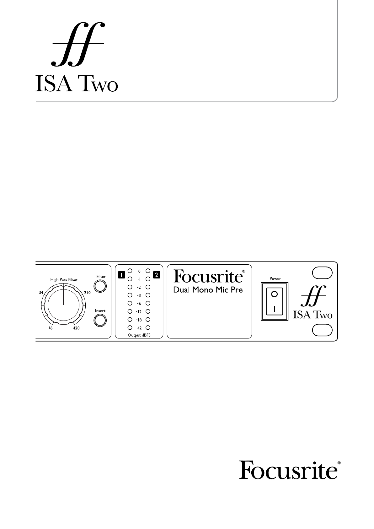
The ISA Two provides two of Focusrite’s prestigious transformer-based microphone preamps. It
features the same classic circuitry and renowned audio quality found in the original at a new level
of affordability. With selectable input impedance, direct instrument inputs and insert points, the ISA
Two creates the perfect front end for the discerning recording professional.
First introduced in 1985, the ISA microphone preamp holds a reputation for outstanding transparency
along with subtle warmth contributed by transformer core saturation. The addition of a variable
impedance circuit allows ISA users to perfectly match the preamp with any microphone, or to use
different settings creatively to shape the sound of the microphone. Unchanged for decades, the ISA
microphone preamp topology offers incredible clarity and the signature Focusrite sound that makes
it the top choice among many audio professionals today.
Features
• Two ISA series transformer-based preamps
• Selectable input impedance
• Two front panel instrument inputs
• Dedicated analogue insert points
English
• Variable high pass filter
Box Contents
• ISA Two
• IEC Power cable
• Printed User Guide in English, French and German
5
Page 6

English
GETTING STARTED AND POWERING UP
The ISA Two is a high quality two-channel preamplifier, which can be used to record microphone,
line-level and instrument sources. Microphones and line-level sources are connected at the rear
panel, whilst instruments are plugged directly into the front panel. The front panel also has gain
controls and other controls such as phantom power and input impedance selection. LED peak meters
are provided, with a calibration control at the rear panel, to ensure a suitable signal level is achieved.
An on-off switch on the front panel applies power to the unit, providing the supplied IEC mains lead is
connected to the socket on the rear. Please make sure that the ISA Two is turned on before powering
any devices connected to the outputs.
The IEC mains lead supplied with the unit should have the correct moulded plug for your country.
The wiring colour code used is:
Live Neutral Earth
For units shipped to the USA, Canada, Taiwan and Japan: Black White Green
For units shipped to any other country: Brown Blue Green and Yellow
6
Page 7

HARDWARE FEATURES
Front Panel
English
3 86
1 10 1112 7 2 4 95
3 86
1 107 2 4 95
1. Input switch: selects the input source (mic, line or instrument)
2. Gain control: sets the gain of the input signal in stepped values of 10 dB
3. 30-60 switch: selects the range of the Gain control (0 to +30 dB, or +30 to +60 dB). The default
range is 0 to +30 dB
4. Trim control: allows an additional 20 dB of gain to be applied to a mic/line-level signal, or can
be used as a gain control for the Instrument Inputs
5. Phantom power switch: supplies +48 V to the corresponding mic input on the rear panel
6. Z In switch: sets the mic input impedance to 600 Ω (Low), 1.4 kΩ (ISA 110), 2.4 kΩ (Med) or
6.8 kΩ (High)
7. Phase switch: inverts the phase of the signal
8. Filter switch: activates a high pass filter (HPF)
9. Filter control: selects the frequency of the high pass filter between 16 Hz-420 Hz
10. Insert: allows the signal to be sent to additional external processors (via the send and return
connectors on the rear panel) prior to the output
11. Peak LED meters: show the main output levels in dBFS
12. Instrument Inputs: for connecting high impedance instruments such as guitars
Front Panel Sections
Input (1)
Pressing Input steps through each of the three inputs, as indicated by the corresponding LEDs.
When the Mic LED is lit, the microphone input is active. An XLR input for a microphone, as well as
3-pole (TRS) ¼” inputs for line-level sources, can be found on the rear panel. A 2-pole (TS) ¼” input
for an instrument (DI) is available on the front panel.
Mic input gain (2)
With the mic input selected, the user has access to the full gain range in 10 dB steps from 0 dB to
+60 dB. The range of operation of the gain control is determined by the setting of the mic gain range
switch (3) - see following page:
7
Page 8

English
Mode 1: Mic Gain Range 0-30
With the 30-60 switch (3) off, the stepped Gain control operates over a gain range of 0 dB to +30
dB, the gain setting being indicated on the front panel by the outer arc of numbers around the Gain
control.
Mode 2: Mic Gain Range 30-60
With the 30-60 switch (3) on (illuminated), the stepped gain dial operates over a gain range of +30 dB
to +60 dB, the gain setting being indicated on the front panel by the outer arc of numbers around the
gain knob. An additional 20 dB of gain can be applied to the signal after the mic/line stepped gain
control using the Trim control (4). (See Trim control text below for a full explanation).
Line Input Gain (2)
With the line input selected, the user has access to gain settings from –20 dB to +10 dB in 10 dB
steps, indicated on the front panel by the inner arc of numbers around the stepped gain knob. The
30-60 switch (3) is inactive when the line input is selected. An additional 20 dB of gain can be applied
to the signal after the stepped mic/line gain using the Trim control (4). (See the Trim control text
below for a full explanation.)
Trim - Mic or Line Modes (4)
The Trim control provides additional gain of up to +20 dB when mic or line inputs are selected. The
level of trim chosen is indicated on the front panel by the inner arc of numbers around the trim
knob. The additional 20 dB of gain that can be applied to the mic or line signal is very useful for two
reasons:
• When high gain is required - using trim in conjunction with a mic gain of +60 dB gives a
maximum available gain of +80 dB, making it very useful for getting good digital recording
levels from very low output dynamic and ribbon microphones.
• Gain adjustment during recording - when small amounts of gain adjustment are needed to
correct performance level variations during recording, use the Trim control rather than the
stepped mic/line Gain control, as switching the 10 dB gain steps would be too intrusive. It is
therefore good practice to apply some trim before using the 10 dB stepped gain control to find
the optimum recording level so that the Trim control can be used to gently add or reduce gain
later, if so required.
Trim - Inst Input Mode (4)
The Trim control provides variable gain of +10 dB to +40 dB when instrument mode is selected. The
level of trim chosen is indicated on the front panel by the outer arc of numbers around the Trim
control. Please note that the stepped Gain control (2) is not active in instrument mode, and gain is
only provided by the Trim control.
+48V (5)
Pressing the +48V switch (illuminated when active) provides phantom power, as required by
condenser microphones, at the rear panel XLR microphone connector. If you are unsure whether
your microphone requires phantom power, refer to its handbook, as it is possible to damage some
microphones (most notably ribbon microphones) by applying phantom power to them.
8
Page 9

Z In - Input Impedance (6)
Pressing the Z In switch steps through each of the four transformer preamp input impedance values,
as indicated by the corresponding LEDs. By selecting different values for the impedance of the ISA
Two transformer input (mic or line), the performance of both the ISA Two preamp and the microphone
connected can be tailored to set the desired level and frequency response.
The impedance values are as follows:
• Low – 600 Ω
• ISA 110 – 1.4 kΩ
• Med – 2.4 kΩ
• High – 6.8 kΩ
Phase (7)
Pressing the Phase switch (illuminated when active) inverts the phase of the selected input to correct
phase problems when using multiple microphones, or when incorrect wiring polarity has occurred.
Filter (8)
Pressing the Filter switch (illuminated when active) makes the high pass filter active in the audio
path. This is useful for removing any unwanted bass caused by proximity effect or rumble.
English
High Pass Filter Control (9)
The high pass filter is adjustable between 16 Hz and 420 Hz, with an 18 dB/octave roll-off.
Insert (10)
Pressing the Insert switch (illuminated when active) routes the insert return socket to the output
instead of the direct mic, line or instrument signal. The input signal is permanently routed to the
insert send output on the rear panel. Insert allows the input signal to be routed to other hardware
for processing before returning back into the ISA Two.
Metering (11)
ISA Two’s two front panel LED meters display the peak level at the output, after any insert processors,
and are calibrated to meter the dBFS scale.
Calibration
The LED meters can be calibrated using the PEAK METER CALIBRATION control on the rear panel
(see the Rear Panel diagram for the exact location) enabling the 0 dBFS point on the LED meters to
correspond with that on an external A/D converter. The meters are calibrated in the following way:
LED Meters
To calibrate the LED meters, use the rear panel PEAK METER CALIBRATION control. With the control
in the default central (‘detented’) position, 0 dBFS is equivalent to an analogue audio level of +22 dBu.
Rotating the control in either direction sets a new value for 0 dBFS from +16 dBu (fully anticlockwise)
to +24 dBu (fully clockwise). When performing a factory reset, the peak meter calibration control
must be in the central (‘detented’) position.
9
Page 10

English
Rear Panel
3
157 24
36
1. MIC INPUT (female XLR)
2. LINE INPUT (3-pole ¼”- TRS)
3. Insert SEND: sends the main mic/line/inst input for additional signal processing (3-pole ¼”TRS)
4. Insert RETURN: for externally processed signals - the Insert switch (10) on the front panel
should be active when in use (3-pole ¼”- TRS)
5. OUTPUT: the main mic/line/inst input signal, or the return signal when active, as selected by
the input switch on the front panel (male XLR)
6. PEAK METER CALIBRATION: allows calibration of the peak meters (see Metering for details)
7. Mains IEC connector
15 24
Rear Panel Sections
Analogue Inputs
The MIC INPUT and LINE INPUT can be used to connect an analogue source to the ISA Two. Phantom
power can be applied to the MIC INPUT connector by enabling the +48V switch. Note that phantom
power can be applied to the connector whether or not a microphone is connected, and is not recalled
after a power cycle. If you are unsure whether your microphone requires phantom power, refer to
its handbook. It is possible to damage some microphones (most notably ribbon microphones) by
providing phantom power to them.
Line-level signals use a balanced jack connector. Once connected, set the Input switch on the front
panel to Line.
Analogue Outputs
The analogue outputs at the rear of ISA Two use male XLR connectors.
Insert
The two insert connectors are for sending the selected signal to an external processor, such as a
compressor, and returning the processed signal back into the ISA Two. Connect SEND to the input of
the external processor and RETURN to the output of the processor, preferably with balanced cables
as both connectors are ¼” 3-pole TRS jacks. Make sure that the Insert switch is activated on the
front panel if using the insert facility.
10
Page 11

Setting a Microphone Level
To record a microphone signal using the ISA Two:
1. Using an XLR cable connect the microphone to one of the MIC INPUTS on the rear panel.
2. Select Mic as the input source using the Input switch.
3. If required, activate phantom power using the +48V switch. If you are unsure whether your
microphone requires phantom power, refer to its handbook. It is possible to damage some
microphones (most notably ribbon microphones) by providing phantom power to them.
4. Set the gain of the microphone using the Gain and Trim controls on the front panel while
observing the LED meter. The stepped gain sets the level in 10 dB steps, with Trim providing
a further 20 dB. If the level is too low, use the 30-60 switch to increase the gain range.
5. Use the Z In switch to adjust the input impedance (see “Mic Preamp Input Impedance” on
page 12 for details).
6. Activate the Phase and Filter switches if required.
7. The microphone signal will then be sent to the corresponding rear panel OUTPUT connector.
Setting a Line-level Signal
To record a line-level signal with the ISA Two:
1. Connect the line-level signal, using a ¼” 3-pole TRS jack cable, to one of the rear panel LINE
INPUTS.
English
2. Select Line as the input source using the front panel Input switch.
3. Set the gain of the line-level signal using the Gain and Trim controls on the front panel while
observing the LED meter. The stepped gain sets the level in 10 dB steps, with Trim providing
a further 20 dB. The 30-60 switch does not affect the line input.
4. The line-level signal signal will then be sent to the corresponding rear panel OUTPUT
connector.
Using the Instrument Input
To record a guitar, bass or other similar instrument with the ISA Two:
1. Plug the instrument directly into one of the Instrument Inputs on the front panel.
2. Select Inst as the input source using the front panel Input switch.
3. Set the gain of the instrument using the Trim control and observing the LED meter.
4. The instrument signal will then be sent to the corresponding rear panel OUTPUT connector.
11
Page 12

English
APPLICATIONS
Mic Preamp Input Impedance
A major element of the sound of a mic preamp is related to the interaction between the specific
microphone being used and the type of mic preamp circuit it is connected to. This interaction primarily
affects the level and frequency response of the microphone, as follows:
Level
A professional microphone tends to have a low output impedance and so more level can be achieved
with this type of microphone by selecting the higher impedance positions of the ISA Two mic preamp.
Frequency response
Microphones with defined presence peaks and tailored frequency responses can be further
‘enhanced’ by choosing different impedance settings. Choosing higher input impedance values will
tend to emphasise the high frequency response of the microphone connected, allowing you to get
improved ambient information and high-end clarity, even from average-performance microphones.
Various microphone/ISA Two preamp impedance combinations can be tried to achieve the appropriate
amount of colouration for the instrument or voice being recorded. To understand how to use the
impedance selection creatively, it may be useful to read the following section on how the microphone
output impedance and the mic preamp input impedance interact.
Switchable Impedance: In Depth Explanation
Dynamic moving coil and condenser microphones
Almost all professional dynamic and condenser microphones are designed to have a relatively low
nominal output impedance of between 150 Ω and 300 Ω at 1 kHz. Microphones are designed to have
such low output impedances because the following advantages result:
• They are less susceptible to noise pickup
• They can drive long cables without high frequency roll-off due to cable capacitance
The side effect of having such a low output impedance is that the mic preamp input impedance has
a major effect on the output level of the microphone. Low preamp impedance loads the microphone
output voltage, and emphasises any variation of mic output impedance with frequency. Matching the
mic preamp input impedance to the microphone output impedance (e.g., making a preamp input
impedance 200 Ω to match a 200 Ω microphone) still reduces the microphone output and signal-tonoise ratio by 6 dB, which is undesirable.
To minimise microphone loading, and to maximise signal-to-noise ratio, preamps have traditionally
been designed to have an input impedance about ten times greater than the average microphone,
around 1.2 kΩ to 2 kΩ. (The original Focusrite ISA 110 preamp design followed this convention and
has an input impedance of 1.4 kΩ at 1 kHz.) Input impedance settings greater than 2 kΩ tend to
make the frequency-related variations of microphone outputs less significant than at low impedance
settings. Therefore high input impedance settings yield a microphone performance that is flatter
in the low and mid frequency areas and boosted in the high frequency area when compared to low
impedance settings.
Ribbon microphones
The impedance of a ribbon microphone is worthy of special mention, as this type of microphone is
affected enormously by mic preamp impedance. The ribbon impedance within this type of microphone
is incredibly low, around 0.2 Ω, and requires an output transformer to convert the extremely low
12
Page 13

voltage it can generate into a signal capable of being amplified by a mic preamp. The ribbon
microphone output transformer typically has a ratio of around 1:30 (primary: secondary) to increase
the ribbon voltage to a useful level, and this transformer ratio also has the effect of increasing the
output impedance of the mic to around 200 Ω at 1 kHz. This transformer impedance, however, varies
greatly with frequency - it can almost double at some frequencies (known as the resonance point)
and tends to roll off to very small values at low and high frequencies.
Therefore, as with the dynamic and condenser microphones, the mic preamp input impedance has
an effect on the signal levels and frequency response of the ribbon microphone output transformer,
and thus the ‘sound quality’ of the microphone. It is recommended that a mic preamp connected to
a ribbon microphone should have an input impedance of at least 5 times the nominal microphone
impedance.
For a ribbon microphone impedance of 30 Ω to 120 Ω, the input impedance of 600 Ω (Low) will work
fine. For 120 Ω to 200 Ω ribbon microphones, the input impedance setting of 1.4 kΩ (ISA 110) is
recommended.
Impedance Setting Quick Guide
In general, the following selections will yield these results:
High mic preamp impedance settings
• will generate more overall level
English
• will tend to make the low- and mid-frequency response of the microphone flatter
• will improve the high-frequency response of the microphone
Low mic preamp impedance settings
• will reduce the microphone output level
• will tend to emphasise the low- and mid-frequency presence peaks and resonant points of
the microphone
13
Page 14
English
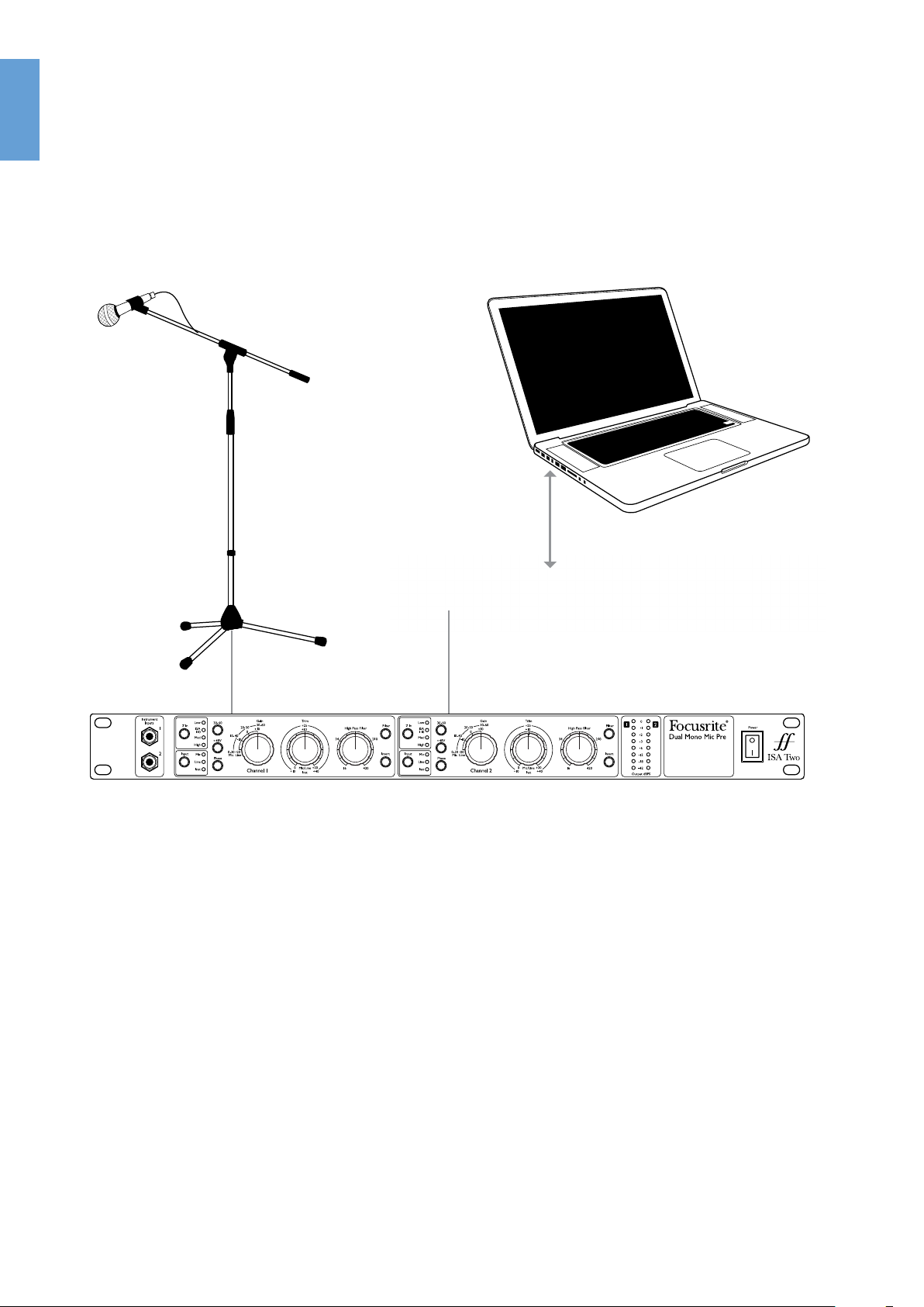
EXAMPLE OF USAGE
Recording an analogue vocal signal to a DAW
14
Page 15

SPECIFICATIONS
Performance Specifications
Maximum Input and Output Levels
+24 dBu with a THD+N < 0.01% at 1kHz measured with 0 dBu input
Maximum Output Level
level, with 150 Ω source impedance and 22Hz/22kHz band-pass
filter
English
Maximum Microphone
Transformer Input Level
Mic Input Response
Gain range
Input Impedance
EIN
(Equivalent Input Noise)
Noise
+7 dBu with a THD+N < 0.7% at 1kHz measured at 0 dB of gain with
150 Ω source impedance and 22Hz/22kHz band-pass filter
0 dB to +60 dB in 10 dB steps, plus 0 dB to +20 dB continuously
variable trim
Low = 600 Ω
Switched Impedance setting
Equivalent Input Impedance at 1 kHz
Measured at 60 dB of gain with 150 Ω
source impedance and 22 Hz-22 kHz
band pass filter
Noise at output with unity gain (0 dB)
and 22 Hz-22 kHz band pass filter
ISA 110 = 1.4 kΩ
Med = 2.4 kΩ
High = 6.8 kΩ
-127 dB
-97 dBu
Signal-to-Noise Ratio
Total Harmonic Distortion
+ Noise
Measured with 150 Ω source impedance
and 22 Hz-22 kHz band pass filter
Measured with a -20 dBu input signal at
+30 dB of gain and with a 22 Hz-22 kHz
band pass filter
121 dB relative to max
output +24 dBu
< 0.0007% at 1 kHz
15
Page 16

English
Frequency Response
At minimum gain (0 dB)
At maximum gain (+60 dB)
-0.5 dB at 10 Hz,
-1 dB at 135 kHz, relative
to 1 kHz
-6 dB at 10 Hz,
-1 dB at 115 kHz, relative
to 1 kHz
CMRR (Common Mode
Rejection Ratio)
Crosstalk Channel to
Channel
-94 dB for mic input at 60 Hz for max. output = +24 dBu
-91 dB for mic input at 10 kHz for max. output = +24 dBu
Mic input, with I/P = 0 dBu, gain = 0 dB @ 1 kHz input to channel A,
channel B output = -85 dB
Line Input Response
Gain Range
Input Impedance 10 kΩ from 10 Hz to 200 kHz
Noise
Signal-to-Noise Ratio
-20 dB to +10 dB in 10 dB steps, plus 0 dB to +20 dB continuously
variable trim
Noise at main output with gain at unity
(0 dB) measured with 50 Ω source
impedance and a 22Hz - 22 kHz band
pass filter
Measured with 50 Ω source impedance
and a 22 Hz-22 kHz band pass filter
-97 dBu
121 dB relative to max
output +24 dBu
Total Harmonic Distortion
+ Noise
Frequency Response At unity gain (0 dB)
Crosstalk Channel to
Channel
Measured with a 0 dBu input signal,
+10 dB of gain and a 22 Hz-22 kHz band
pass filter
Line input, with I/P = 0 dBu, gain = 0dB
@ 1 kHz input to channel A
16
< 0.002% at 1 kHz
-0.3 dB at 10 Hz,
-1 dB at 80 kHz, relative
to 1 kHz
Channel B output
= -91 dB
Page 17

Instrument Input Response
Gain Range +10 dB to +40 dB continuously variable trim
Input Impedance > 2 MΩ
English
Noise
Frequency Response
Measured with 22 Hz-22 kHz
band pass filter
At minimum gain (+10 dB)
At maximum gain (+40 dB)
Minimum gain (+10 dB) = -95 dBu
-0.1 dB at 10 Hz,
-1 dB at 115 kHz, relative to 1 kHz
-2.5 dB at 10 Hz,
-1 dB at 110 kHz, relative to 1 kHz
High Pass Filter
Roll-Off 18 dB per octave (3 pole filter)
Frequency Range Continuously variable from 16 Hz to 420 Hz (-3 dB)
Physical and Electrical Characteristics
Weight and Dimensions
W x D x H 480 mm x 280 mm x 44 mm
Weight 3.7 kg
17
Page 18

English
WARRANTY
All Focusrite products are covered by a warranty against manufacturing defects in material
or craftsmanship for a period of one year from the date of purchase. Focusrite in the UK, or its
authorised distributors worldwide, will do their best to ensure that any fault is remedied as quickly
as possible. This warranty is in addition to your statutory rights.
This warranty does not cover any of the following:
Carriage to and from the dealer or factory for inspection or repair
Labour charge if repaired other than by the distributor in the country of purchase or Focusrite in
the UK
Consequential loss or damage, direct or indirect, of any kind, however caused
Any damage or faults caused by abuse, negligence, improper operation, storage or maintenance
If a product is faulty, please first contact the dealer from which the product was purchased. If the
product is to be shipped back, please ensure that it is packed correctly, preferably in the original
packing materials. We will do our best to remedy the fault as quickly as possible.
Please help us to serve you better by registering online at http://www.focusrite.com. Thank you.
ACCURACY
Whilst every effort has been made to ensure the accuracy and content of this manual, Focusrite
Audio Engineering Ltd., makes no representations or warranties regarding the contents.
COPYRIGHT
Copyright 2011 Focusrite Audio Engineering Limited. All rights reserved. No part of this manual may
be reproduced, photocopied, stored on a retrieval system, transmitted or passed to a third party by
any means or in any form without the express prior consent of Focusrite Audio Engineering Limited.
18
Page 19

Mode d’emploi
www.focusrite.com
Page 20

INSTRUCTIONS DE SÉCURITÉ IMPORTANTES
Français
1. Lisez ces instructions.
2. Conservez ces instructions.
3. Tenez compte de tous les avertissements.
4. Suivez toutes les instructions.
5. N'utilisez pas cet appareil avec de l'eau à proximité.
6. Nettoyez-le uniquement avec un chiffon sec.
7. Ne l'installez pas près de sources de chaleur telles que des radiateurs, bouches de chauffage,
poêles ou autres appareils (y compris des amplificateurs) produisant de la chaleur.
8. Évitez de marcher sur le cordon d'alimentation et de le pincer, en particulier au niveau des
fiches, des prises secteur, et du point de sortie de l'appareil.
9. N'utilisez que des fixations/accessoires spécifiés par le fabricant.
10. Utilisez-le uniquement avec le chariot, socle, trépied, support ou table spécifié par le fabricant
ou vendu avec l'appareil. Si un chariot est utilisé, faites attention à ne pas être blessé par un
renversement lors du déplacement de l'ensemble chariot/appareil.
11. Débranchez cet appareil en cas d'orage ou de non utilisation prolongée.
12. Confiez toute réparation à des techniciens de maintenance qualifiés. Une réparation est
nécessaire si l'appareil a été endommagé d'une quelconque façon, par exemple si le cordon
ou la fiche d'alimentation est endommagé, si du liquide a été renversé sur l'appareil ou si
des objets sont tombés dedans, si l'appareil a été exposé à la pluie ou à l'humidité, s'il ne
fonctionne pas normalement, ou s'il est tombé.
13. Aucune source de flamme nue, comme une bougie allumée, ne doit être placée sur l'appareil.
AVERTISSEMENT : des niveaux de pression sonore excessifs dans les écouteurs ou dans le casque
peuvent entraîner une perte auditive.
ATTENTION : POUR RÉDUIRE LE RISQUE D'ÉLECTROCUTION, NE
RETIREZ PAS LE CAPOT (OU L'ARRIÈRE). AUCUNE PIÈCE INTERNE N'EST
RÉPARABLE PAR L'UTILISATEUR.
CONFIEZ TOUTE RÉPARATION À UN SERVICE APRÈS-VENTE QUALIFIÉ.
Le symbole d'éclair à tête de flèche dans un triangle équilatéral sert
à prévenir l'utilisateur de la présence dans l'enceinte du produit d'une
"tension dangereuse" non isolée d'une grandeur suffisante pour
constituer un risque d'électrocution pour les personnes.
Le point d'exclamation dans un triangle équilatéral sert à prévenir
l'utilisateur de la présence d'instructions importantes de fonctionnement
et de maintenance (entretien) dans les documents accompagnant
l'appareil.
20
Page 21

DÉCLARATION ENVIRONNEMENTALE
Pour le Canada
À destination de l’utilisateur :
This Class B digital apparatus complies with Canadian ICES-003.
Cet appareil numérique de la classe B est conforme à la norme NMB-003 du Canada.
Avis RoHS
Focusrite Audio Engineering Limited s'est conformé, ainsi que ce produit s'il y a lieu, à la directive 2002/95/EC de l'Union Européenne
sur la restriction de l'utilisation de certaines substances dangereuses ou RoHS (Restrictions of Hazardous Substances).
Français
21
Page 22

TABLE DES MATIÈRES
Français
INSTRUCTIONS DE SÉCURITÉ IMPORTANTES . . . . . . . . . . . . . . . . . . . . . . . . . . . . . . . . . . . . . . 21
TABLE DES MATIÈRES..........................................................22
GÉNÉRALITÉS ................................................................23
Introduction ................................................................23
Caractéristiques ............................................................23
Contenu de l’emballage ......................................................23
PRISE EN MAIN ET MISE SOUS TENSION..........................................24
DESCRIPTION DE L'APPAREIL ...................................................25
Face avant .................................................................25
Sections de la face avant......................................................25
Face arrière ................................................................28
Sections de la face arrière ....................................................28
APPLICATIONS ................................................................30
Impédance commutable : explication détaillée ...................................30
EXEMPLE D'UTILISATION.......................................................32
CARACTÉRISTIQUES TECHNIQUES ...............................................33
Performances ..............................................................33
Caractéristiques physiques et électriques .......................................35
GARANTIE.................................................................... 35
EXACTITUDE DES INFORMATIONS................................................35
COPYRIGHT .................................................................. 35
22
Page 23

GÉNÉRALITÉS
Introduction
L'ISA Two intègre deux des prestigieux préamplis microphone à transformateur de Focusrite. Il
bénéficie du circuit classique et de la qualité audio réputée de l'original mais en étant plus abordable.
Avec une impédance d'entrée réglable, des entrées directe pour instrument et des points d'insertion,
l'ISA Two est le frontal parfait pour le professionnel de l'enregistrement exigeant.
Sorti en 1985, le préampli microphone ISA possède une réputation de transparence hors du commun
associée à une délicate chaleur apportée par la saturation du cœur transformateur. L'ajout d'un
circuit à impédance variable permet aux utilisateurs de l'ISA de parfaitement adapter le préampli
à tout microphone ou d'utiliser des réglages différents de façon créative pour façonner le son du
microphone. Inchangée depuis des décennies, la topologie du préampli microphone ISA offre une
clarté incroyable et le son estampillé Focusrite qui en font aujourd'hui le premier choix de nombreux
professionnels de l'audio.
Caractéristiques
• Deux préamplis à transformateur de la gamme ISA
• Impédance d'entrée réglable
• Deux entrées instrument en face avant
Français
• Points d'insertion analogique dédiés
• Filtre passe-haut variable
• Indicateurs de niveau précis à DEL pour les deux canaux
Contenu de l’emballage
• ISA Two
• Câble d'alimentation IEC
• Mode d'emploi imprimé en anglais, français et allemand
23
Page 24

PRISE EN MAIN ET MISE SOUS TENSION
Français
L’ISA Two est un préamplificateur de haute qualité à deux canaux qui peut servir à enregistrer des
microphones, des sources de niveau ligne et des instruments. Les microphones et sources de niveau
ligne se connectent en face arrière, tandis que les instruments se branchent directement en face
avant. La face avant possède aussi des commandes de gain et aussi d'autres commandes telles que
la sélection d'alimentation fantôme et d'impédance d'entrée. Des crête-mètres à DEL sont inclus,
avec une commande decalibrage en face arrière, pour assurer l'obtention d'un niveau de signal
convenable.
Un interrupteur à deux positions fournit l’alimentation à l’unité, à condition bien sûr que le câble
d’alimentation électrique IEC soit connecté à l’entrée électrique en face arrière. Veuillez vous assurer
que l’ISA Two est sous tension avant d’allumer tout appareil relié à ses sorties.
Le câble d’alimentation électrique IEC fourni avec l’unité doit posséder la prise moulée adaptée à
votre pays. Le code couleur du câblage est le suivant :
Phase Neutre Terre
Pour les unités livrées aux USA, au Canada, à Taiwan et
au Japon :
Pour les unités livrées dans tous les autres pays : Marron Bleu Vert et jaune
Noir Blanc Vert
24
Page 25

DESCRIPTION DE L'APPAREIL
Face avant
3 86
1 10 1112 7 2 4 95
3 86
1 107 2 4 95
1. Sélecteur d'entrée : sélectionne la source d'entrée (micro [MIC], ligne [LINE] ou instrument
[INST])
2. Commande de gain : sélectionne le gain du signal d’entrée par paliers de 10 dB
3. Sélecteur 30-60 : sélectionne la plage de gain de la commande Gain (0 à 30 dB ou 30 à 60 dB).
La plage par défaut est 0 à 30 dB
4. Commande Trim : permet d'appliquer un gain supplémentaire de 20 dB à un signal de niveau
micro/ligne, ou peut servir de commande de gain pour les entrées instrument
5. Interrupteur d'alimentation fantôme : fournit +48 V à l'entrée micro de la face arrière
6. Sélecteur Z In : règle l'impédance de l'entrée micro sur 600 Ω (Low), 1,4 kΩ (ISA 110), 2,4 kΩ
(Med) ou 6,8 kΩ (High)
7. Inverseur de phase : inverse la phase du signal
Français
8. Commutateur de filtre : active un filtre passe-haut (HPF)
9. Commande de filtre : sélectionne la fréquence du filtre passe-haut dans la plage 16 Hz 420 Hz
10. Insert : permet au signal d'être envoyé à des processeurs externes supplémentaires (via les
connecteurs de départ et retour de la face arrière) avant la sortie
11. Crête-mètres à DEL : affichent les niveaux des niveaux générales en dBFS
12. Entrées instrument : pour brancher des instruments à haute impédance tels que des guitares
Sections de la face avant
Entrée (1)
Presser Input passe en revue les trois entrées, comme indiqué par les DEL correspondantes. Quand
la DEL Mic est allumée, c'est l'entrée microphone qui est active. Une entrée XLR pour microphone
ainsi que des entrées jack 6,35 mm 3 points (TRS) pour les sources de niveau ligne se trouvent en
face arrière. Une entrée jack 6,35 mm 2 points (TS) pour instrument (DI) est disponible en face avant.
Gain d’entrée micro (2)
Avec l’entrée micro (Mic) sélectionnée, l’utilisateur a accès à la totalité de la plage de gain par paliers
de 10 dB, de 0 à +60 dB. La plage de fonctionnement de la commande de gain est déterminée par le
réglage du sélecteur de plage de gain de micro (3) – voir page suivante :
25
Page 26

Français
Mode 1 : plage de gain de micro 0-30
Avec le commutateur 30-60 (3) non enclenché, le sélecteur de gain à paliers fonctionne sur une
plage de 0 à +30 dB, le niveau de gain choisi étant indiqué en face avant par l’arc extérieur de valeurs
autour de la commande Gain.
Mode 2 : plage de gain de micro 30-60
Avec le commutateur 30-60 (3) enclenché (allumé), le sélecteur de gain à paliers fonctionne sur une
plage de 30 à 60 dB, le niveau de gain choisi étant indiqué en face avant par l’arc extérieur de valeurs
autour de la commande Gain. Un gain supplémentaire de 20 dB peut être appliqué au signal après
le bouton de gain micro/ligne à paliers à l'aide de la commande Trim (4) (voir le paragraphe sur la
commande Trim ci-dessous pour une explication complète).
Gain d’entrée ligne (2)
Avec l’entrée ligne (Line) sélectionnée, l’utilisateur a accès à des réglages de gain allant de –20
à +10 dB par paliers de 10 dB, indiqués en face avant par l’arc intérieur de valeurs autour de la
commande de gain à paliers. Le sélecteur 30-60 (3) est inactif quand l'entrée ligne est sélectionnée.
Un gain supplémentaire de 20 dB peut être appliqué au signal après le bouton de gain micro/ligne à
l'aide du bouton (Trim ) (voir le paragraphe sur la commande Trim ci-dessous pour une explication
complète).
Trim - Modes Mic ou Line (4)
La commande Trim fournit un gain supplémentaire pouvant atteindre +20 dB quand les entrées
micro ou ligne sont sélectionnées. Le niveau de compensation (Trim) choisi est indiqué en face avant
par l'arc de graduation interne entourant le bouton Trim. Le gain supplémentaire de 20 dB qui peut
être appliqué au signal micro ou ligne est très utile pour deux raisons :
• Quand un gain élevé est requis
L’emploi de la commande Trim en conjonction avec le gain de micro de 60 dB donne au total
jusqu’à 80 dB de gain, ce qui est très utile pour obtenir de bons niveaux d’enregistrement
numérique à partir d’une dynamique de sortie très basse et de microphones à ruban.
• Réglage de gain durant l’enregistrement
Quand de petits réglages de gain sont nécessaires pour corriger des variations de niveau
d’interprétation durant un enregistrement, utilisez la commande Trim plutôt que le sélecteur
de gain micro/ligne à paliers, car passer d’un palier de gain à un autre éloigné de 10 dB
serait beaucoup trop audible. Il est par conséquent conseillé d’appliquer un peu de gain avec
la commande Trim avant d’utiliser le sélecteur de gain par paliers de 10 dB afin de trouver
le niveau d’enregistrement optimal pour que la commande Trim puisse ensuite servir à
délicatement augmenter ou réduire le gain si nécessaire.
Trim - Mode d'entrée Inst (4)
La commande Trim procure un gain variable de +10 dB à +40 dB quand le mode instrument est
sélectionné. Le niveau de compensation (Trim) choisi est indiqué en face avant par l'arc de graduation
externe entourant le bouton Trim. Veuillez notez que la commande de gain par paliers (2) n'est pas
active en mode instrument et que le gain n'est géré que par la commande Trim.
+48V (5)
Presser le commutateur +48V (allumé quand il est activé) fournit une alimentation fantôme
convenant aux microphones à condensateur par le connecteur XLR de microphone en face arrière.
Si vous n’êtes pas sûr que votre microphone ait besoin d’une alimentation fantôme, référez-vous
à son manuel car il est possible d’endommager certains microphones (surtout les microphones à
ruban) si on leur envoie une alimentation fantôme.
26
Page 27

Z In - Impédance d'entrée (6)
Presser le commutateur Z In fait passer en revue les quatre valeurs d’impédance du préampli
transformateur, comme indiqué par les DEL correspondantes. En sélectionnant différentes valeurs
pour l’impédance de l’entrée du transformateur de l’ISA Two, les performances du préampli de
l’ISA Two et du microphone connecté peuvent être adaptées afin obtenir le niveau et la réponse en
fréquence désirés.
Les valeurs d’impédance sont les suivantes :
• Low – 600 Ω
• ISA 110 – 1,4 kΩ
• Med – 2,4 kΩ
• High – 6,8 kΩ
Phase (7)
Presser le commutateur Phase (allumé quand il est activé) inverse la phase de l’entrée sélectionnée
pour corriger les problèmes de phase lors de l’emploi de plusieurs microphones ou en cas de polarité
incorrecte due au câblage.
Filter (8)
Presser le commutateur Filter (allumé quand il est activé) active le filtre passe-haut sur le trajet
audio. C’est utile pour supprimer les graves indésirables causés par un effet de proximité ou un
grondement.
Français
Commande High Pass Filter (9)
Elle règle le filtre passe-haut entre 16 Hz et 420 Hz, avec une pente de 18 dB/octave.
Insert (10)
Presser le commutateur Insert (allumé quand il est activé) envoie à la sortie la prise de retour d'insert
plutôt que le signal direct de micro, ligne ou instrument. Le signal entrant est en permanence routé
vers la sortie de départ d'insert en face arrière. L'insert permet au signal entrant d'être envoyé à un
autre équipement pour traitement avant retour dans l'ISA Two.
Mesure de niveau (11)
Les deux indicateurs de niveau à DEL de la face avant de l'ISA Two affichent le niveau crête des
signaux de l'entrée sélectionnée (avec le sélecteur Input) et sont calibrés pour une graduation dBFS.
Calibrage
Les indicateurs de niveau à DEL peuvent être calibrés à l'aide de la commande PEAK METER
CALIBRATION de la face arrière (voir la section Face arrière pour son emplacement exact) permettant
au point 0 dBFS des indicateurs de niveau à DEL de correspondre avec celui d'un convertisseur A/N
externe. Les indicateurs de niveau se calibrent de la façon suivante :
Indicateurs de niveau
Pour calibrer les indicateurs de niveau, utilisez la commande PEAK METER CALIBRATION de la
face arrière. Avec la commande en position centrale par défaut ("sur le cran"), 0 dBFS correspond à
un niveau audio analogique de +22 dBu. Tourner la commande dans l'une ou l'autre des directions
établit une nouvelle valeur pour le 0 dBFS, allant d'un équivalent +16 dBu (à fond dans le sens antihoraire) à +24 dBu (à fond dans le sens horaire).
27
Page 28

Face arrière
Français
3
157 24
36
1. MIC INPUT (XLR femelle) : entrée micro
2. LINE INPUT (jack 6,35 mm 3 points [TRS]) : entrée ligne
3. SEND : départ de l'entrée micro/ligne/instrument pour un traitement supplémentaire du
signal (jack 6,35 mm 3 points [TRS])
4. RETURN : pour recevoir les signaux traités en externe – le commutateur Insert (10) de la face
avant doit être enclenché pour utiliser cette prise (jack 6,35 mm 3 points [TRS])
5. OUTPUT : sortie générale du signal d'entrée micro/ligne/instrument comme choisi par le
sélecteur d'entrée de la face avant (XLR mâle)
6. PEAK METER CALIBRATION : permet le calibrage des crête-mètres (voir Mesure de niveau
pour des détails)
7. Connecteur d'alimentation électrique IEC
15 24
Sections de la face arrière
Entrées analogiques
Les entrées MIC INPUT et LINE INPUT peuvent servir à brancher une source analogique à l'ISA
Two. Une alimentation fantôme peut être fournie au connecteur MIC INPUT en enclenchant le
commutateur +48V (5). Notez que l'alimentation fantôme peut être fournie au connecteur, qu'un
microphone soit ou non connecté. Si vous n'êtes pas sûr que votre microphone nécessite une
alimentation fantôme, référez-vous à son mode d'emploi. Il est possible d'endommager certains
microphones (plus particulièrement les microphones à ruban) en leur fournissant une alimentation
fantôme.
Les signaux de niveau ligne utilisent un connecteur jack symétrique. Une fois la connexion faite,
réglez le sélecteur Input (1) de la face avant sur Line.
Sorties analogiques
Les sorties analogiques à l'arrière de l'ISA Two utilisent des connecteurs XLR mâles.
Insert
Les deux connecteurs d'insert servent à envoyer (Send) le signal sélectionné à un processeur externe,
tel qu'un compresseur, et à recevoir en retour (Return) dans l'ISA Two le signal traité. Reliez SEND à
l'entrée du processeur externe et RETURN à la sortie du processeur, de préférence avec des câbles
symétriques car les deux connecteurs sont des jacks 6,35 mm 3 points (TRS). Assurez-vous que le
commutateur Insert (10) est activé en face avant si vous utilisez cette possibilité d'insertion.
28
Page 29

Réglage d'un niveau de microphone
Pour enregistrer un signal de microphone avec l'ISA Two :
1. Avec un câble XLR, branchez le microphone à l'entrée MIC INPUT de la face arrière.
2. Sélectionnez Mic comme source d'entrée avec le sélecteur Input (1).
3. Si nécessaire, activez l'alimentation fantôme avec le commutateur +48V (5) Si vous n'êtes
pas sûr que votre microphone nécessite une alimentation fantôme, référez-vous à son mode
d'emploi. Il est possible d'endommager certains microphones (plus particulièrement les
microphones à ruban) en leur fournissant une alimentation fantôme.
4. Réglez le gain du microphone avec les commandes Gain (2) et Trim (4) de la face avant tout en
surveillant l'indicateur de niveau à DEL. Le gain à paliers règle le niveau par paliers de 10 dB
tandis que Trim fournit 20 dB supplémentaires. Si le niveau est trop bas, utilisez le sélecteur
30-60 (3) pour augmenter la plage de gain.
5. Utilisez le sélecteur Z In pour régler l'impédance d'entrée (voir “Impédance d’entrée du
préampli micro” en page 30 pour des détails).
6. Activez les commutateurs Phase (7) et Filter (8) si nécessaire.
7. Le signal de microphone sera alors envoyé au connecteur de sortie OUTPUT de la face arrière.
Réglage d'un signal de niveau ligne
Pour enregistrer un signal de niveau ligne avec l'ISA Two :
Français
1. Faites entrer le signal de niveau ligne à l'aide d'un câble jack 6,35 mm 3 points (TRS) dans le
connecteur d'entrée LINE INPUT de la face arrière.
2. Sélectionnez Line comme source d'entrée à l'aide du sélecteur Input de la face avant (1).
3. Réglez le gain du signal de niveau ligne avec les commandes Gain (2) et Trim (4) de la face
avant tout en surveillant l'indicateur de niveau à DEL. Le gain à paliers règle le niveau par
paliers de 10 dB tandis que Trim fournit 20 dB supplémentaires.
4. Le signal de niveau ligne sera alors envoyé au connecteur de sortie OUTPUT de la face arrière.
Emploi de l'entrée instrument
Pour enregistrer une guitare, une basse ou autre instrument similaire avec l'ISA Two :
1. Branchez directement l'instrument dans la prise Instrument Inputs (12) de la face avant.
2. Sélectionnez Inst comme source d'entrée à l'aide du sélecteur Input de la face avant (1).
3. Réglez le gain de l'instrument à l'aide de la commande Trim (4) et en surveillant l'indicateur
de niveau à DEL.
4. Le signal de l'instrument sera alors envoyé au connecteur de sortie OUTPUT de la face arrière.
29
Page 30

APPLICATIONS
Français
Impédance d’entrée du préampli micro
Un élément majeur du son d’un préampli micro est l’interaction entre le microphone utilisé et le
type de circuit de préampli micro auquel il est connecté. Cette interaction affecte principalement le
niveau et la réponse en fréquence du microphone, comme suit :
Niveau
Un microphone professionnel tend à avoir une basse impédance de sortie et donc un niveau plus
élevé peut être obtenu avec ce type de microphone en sélectionnant les positions à plus haute
impédance du préampli micro ISA Two.
Réponse en fréquence
Les microphones ayant des crêtes de présence définies et des réponses en fréquence ajustées
peuvent être encore améliorés par le choix de réglages d'impédance différents. Choisir des valeurs
d’impédance élevées tend à accentuer la réponse des hautes fréquences du microphone connecté,
ce qui vous permet d’obtenir plus d’informations d’ambiance et de clarté dans les aigus, même
à partir de microphones aux performances moyennes. Diverses combinaisons d’impédances de
microphone/préampli ISA Two peuvent être essayées afin d’obtenir la coloration appropriée pour
l’instrument ou la voix à enregistrer. Pour comprendre comment utiliser créativement la sélection
d’impédance, il peut être utile de lire la section suivante sur l’interaction entre l’impédance de sortie
du microphone et l’impédance d’entrée du préampli micro.
Impédance commutable : explication détaillée
Microphones dynamiques à bobine mobile et microphones à condensateur
Quasiment tous les microphones professionnels dynamiques et à condensateur sont conçus pour
avoir une impédance de sortie nominale relativement basse entre 150 Ω et 300 Ω à 1 kHz. Les
microphones sont ainsi conçus en raison des avantages que cela procure :
• Ils sont ainsi moins susceptibles de capter du bruit
• Ils peuvent utiliser de long câbles sans perte des hautes fréquences due à la capacitance du
câble
L’inconvénient d’une impédance de sortie basse est que l’impédance d’entrée du préampli micro a
un effet majeur sur le niveau de sortie du microphone. L'impédance basse du préampli charge la
tension de sortie du microphone, et accentue toute variation d'impédance de sortie du microphone
avec la fréquence. Adapter l'impédance d'entrée du préampli micro à l’impédance de sortie du
microphone (par ex. en réglant l’impédance d’entrée du préampli à 200 Ω pour correspondre à un
microphone à 200 Ω) réduit encore la sortie du microphone et le rapport signal/bruit de 6 dB, ce qui
n’est pas souhaitable.
Afin de minimiser la charge du microphone et pour maximiser le rapport signal/bruit, les préamplis
sont traditionnellement conçus pour avoir une impédance d’entrée environ dix fois plus grande que
celle d’un microphone moyen, entre 1,2 kΩ et 2 kΩ (la conception d'origine du préampli ISA110
Focusrite suivait cette convention avec une impédance d’entrée de 1,4 kΩ à 1 kHz). Les réglages
d’impédance d’entrée supérieurs à 2 kΩ tendent à rendre les variations de sortie de microphone
liées à la fréquence moins significatives qu’à basse impédance. Par conséquent les réglages élevés
d’impédance entraînent des performances de microphone plus plates dans les fréquences basses et
moyennes et renforcées dans les hautes fréquences par rapport aux réglages de basse impédance.
30
Page 31

Microphones à ruban
L’impédance d’un microphone à ruban mérite une mention particulière, car ce type de microphone
est énormément affecté par l’impédance du préampli micro. L’impédance du ruban dans ce type de
microphone est incroyablement basse, autour de 0,2 Ω, et nécessite un transformateur de sortie
pour convertir la tension extrêmement basse produite en un signal pouvant être amplifié par un
préampli. Le transformateur de sortie d’un microphone à ruban nécessite un rapport d’environ
1:30 (primaire : secondaire) pour faire monter la tension du ruban à un niveau exploitable, et ce
rapport du transformateur a aussi pour effet d’augmenter l’impédance de sortie du micro à environ
200 Ω à 1 kHz. Cette impédance de transformateur varie toutefois beaucoup avec la fréquence – elle
peut quasiment doubler pour certaines fréquences (appelées “fréquences de résonance”) et tend à
décliner jusqu’à de très faibles valeurs pour les fréquences basses et hautes.
Par conséquent, comme pour les microphones dynamiques et à condensateur, l’impédance d’entrée
du préampli micro a un impact énorme sur le niveau et la réponse en fréquence des signaux d’un
transformateur de sortie de microphone à ruban, et donc sur la “qualité sonore” du microphone.
Il est recommandé qu’un préampli micro connecté à un microphone à ruban ait une impédance
d’entrée au moins 5 fois supérieure à l’impédance nominale du microphone.
Pour un microphone à ruban d’impédance comprise entre 30 Ω et 120 Ω, l'impédance d'entrée de
600 Ω (Low) conviendra bien. Pour les microphones à ruban d’impédance comprise entre 120 Ω et
200 Ω, le réglage d'impédance d’entrée de 1,4 kΩ (ISA110) est recommandé.
Guide rapide de réglage de l'impédance
En général, les sélections suivantes auront pour résultat :
Français
Des réglages élevés de l’impédance du préampli micro
• donneront plus de niveau
• tendront à rendre plus plate la réponse du microphone pour les fréquences basses et
moyennes
• augmenteront la réponse du microphone pour les hautes fréquences.
Des réglages bas de l’impédance du préampli micro
• réduiront le niveau de sortie du microphone
• tendront à accentuer les crêtes de présence des fréquences basses et moyennes et les
fréquences de résonance du microphone
31
Page 32

EXEMPLE D'UTILISATION
Français
Enregistrement d'un signal de voix analogique dans une station de travail audio numérique
32
Page 33

CARACTÉRISTIQUES TECHNIQUES
Performances
Niveaux d’entrée et de sortie maximums
+24dBu avec un THD+N < 0.01% à 1kHz mesuré pour 0dBu de
Niveau de sortie maximal
Niveau d’entrée
maximum du
transformateur du
microphone
niveau en entrée, avec 150 Ω en impédance de source et 22Hz/22kHz
de filtre passe-bande
+7dBu avec un THD+N < 0.7% à 1kHz mesuré pour 0dB de gain avec
150 Ω source impedance en impédance de source et 22Hz/22kHz de
filtre passe-bande
Réponse de l'entrée micro
Plage de gain
Impédance d’entrée
0 dB à +60 dB par paliers de 10 dB, plus ajustement (Trim) variable
en continu de 0 dB à +20 dB
Sélection de réglage d'impédance
Impédance d'entrée équivalente à 1 kHz
Français
Low = 600 Ω
ISA110 = 1,4 kΩ
Med = 2,4 kΩ
High = 6,8 kΩ
EIN
(bruit équivalent rapporté
en entrée)
Bruit
Rapport signal/bruit
Distorsion harmonique
totale
Réponse en fréquence
Mesuré avec 60 dB de gain et une
impédance source de 150 Ω,
22 Hz-22 kHz
Mesuré au gain unitaire avec
impédance source de 150 Ω,
22 Hz-22 kHz
Mesuré avec impédance source de
150 Ω, 22 Hz-22 kHz
Mesurée avec une entrée à -20 dBu,
+30 dB de gain et impédance source de
150 Ω, 22 Hz-22 kHz
Au gain minimal
Au gain maximal (60 dB)
-127 dB
-97 dB
121 dB par rapport à la
sortie max. de +24 dBu
< 0,0007% à 1 kHz
-0,5 dBr à 10 Hz,
-1 dBr à 135 kHz
-6 dBr à 10 Hz,
-1 dBr à 115 kHz
33
Page 34

Français
CMRR (taux de réjection
de mode commun)
Diaphonie entre canaux
Réponse d'entrée ligne
= 98 dB (canal 1, 1 kHz, gain maximal avec entrée à +24 dBu)
Avec entrée de 10 dB à 1 kHz sur le canal A,
sortie du canal B = 104 dBrA
Avec entrée de 10 dB à 10 kHz sur le canal A,
sortie du canal B = 84 dBrA
Plage de gain
Impédance d’entrée 10 kΩ, de 10 Hz à 200 kHz
Bruit
Rapport signal/bruit
Distorsion harmonique
totale
Réponse en fréquence Au gain unitaire
-20 dB à +10 dB par paliers de 10 dB, plus ajustement (Trim)
variable en continu de 0 dB à +20 dB
Mesuré au gain unitaire avec
impédance source de 50 Ω,
22 Hz-22 kHz
Mesuré avec impédance source de 50 Ω,
22 Hz-22 kHz
Mesurée avec une entrée à 0 dBu, +10
dB de gain et impédance source de
50 Ω, 22 Hz-22 kHz
-97 dBu
121 dB par rapport à la
sortie max. de +24 dBu
< 0,002% à 1 kHz
-0,3 dBr à 10 Hz,
-1 dBr à 80 kHz
Réponse d'entrée instrument
Bruit +10 dB à +40 dB, ajustement (Trim) variable en continu
Plage de gain
Réponse en fréquence
34
Mesurée avec impédance
source de 150 Ω, 22 Hz-22 kHz
À +10 dBu -0,1 dBr à 10 Hz, -1 dBr à 115 kHz
À +40 dBu -2,5 dBr à 10 Hz, -1 dBr à 110 kHz
Gain minimal : -95 dBu
Page 35

Caractéristiques physiques et électriques
Poids et dimensions
L x H x P 480 mm x 280 mm x 44 mm
Poids 3,7 kg
GARANTIE
Tous les produits Focusrite sont couverts par une garantie contre les défauts de pièces et de
fabrication pour une période d'un an à compter de la date d'achat. Focusrite au Royaume-Uni ou ses
distributeurs agréés dans le monde feront de leur mieux pour veiller à solutionner toute défaillance
aussi rapidement que possible. Cette garantie vient en complément de vos droits légaux.
Cette garantie ne couvre pas :
Le transport vers ou depuis le revendeur ou l'usine pour inspection ou réparation.
Les frais de réparation si la réparation n'est pas faite par le distributeur du pays d'achat ou Focusrite
au Royaume-Uni.
Les pertes ou dommages collatéraux, directs ou indirects de quelque sorte que ce soit, qu'elle qu'en
soit la cause.
Les dommages ou pannes causés par de mauvais traitements, la négligence, une utilisation, un
stockage ou une maintenance inadaptés.
Si un produit est défaillant, veuillez d'abord contacter le revendeur chez qui il a été acheté. Si le
produit doit être renvoyé, veuillez vous assurer qu'il est bien emballé, de préférence dans son
emballage d'origine. Nous ferons de notre mieux pour remédier à la panne aussi rapidement que
possible.
Français
Veuillez nous aider à mieux vous servir en vous enregistrant en ligne sur http://www.focusrite.com.
Merci.
EXACTITUDE DES INFORMATIONS
Malgré tous les efforts apportés à la réalisation de ce mode d’emploi, Focusrite Audio Engineering
Ltd. ne garantit pas l’exactitude de son contenu.
COPYRIGHT
Copyright 2011 Focusrite Audio Engineering Limited. Tous droits réservés. Aucune partie de ce mode
d’emploi ne peut être reproduite, photocopiée, stockée sur un système d’archivage, transmise ou
donnée à une tierce partie par quelque moyen ou sous quelque forme que ce soit sans l’autorisation
expresse préalable de Focusrite Audio Engineering Limited.
35
Page 36

Bedienungsanleitung
www.focusrite.com
Page 37

WICHTIGE SICHERHEITSHINWEISE
1. Lesen Sie diese Anleitung.
2. Bewahren Sie diese Anleitung auf.
3. Beachten Sie alle Warnungen.
4. Befolgen Sie alle Anweisungen.
5. Betreiben Sie dieses Gerät nicht in unmittelbarer Nähe von Wasser.
6. Verwenden Sie zum Reinigen des Geräts ausschließlich ein trockenes Tuch.
7. Stellen Sie das Gerät nicht in der Nähe von Wärmequellen wie Heizlüftern, Wärmespeichern,
Öfen oder anderen Wärme produzierenden Geräten (inklusive Verstärkern) auf.
8. Treten Sie nicht auf das Kabel, knicken Sie es nicht und behandeln Sie Stecker und Buchsen
besonders vorsichtig.
9. Verwenden Sie nur vom Hersteller empfohlene Erweiterungen/Zubehörteile.
10. Verwenden Sie nur Rollwagen, Ständer, Stative, Montageklammern oder Tische, die den
Anforderungen des Herstellers entsprechen oder die zum Lieferumfang des Geräts gehören.
Seien Sie beim Transport auf Rollwägen vorsichtig, um Verletzungen durch verrutschende
oder fallende Gegenstände zu vermeiden.
Deutsch
11. Ziehen Sie den Netzstecker des Geräts bei Gewitter und wenn Sie das Gerät längere Zeit nicht
verwenden.
12. Lassen Sie alle Wartungsarbeiten von qualifiziertem Fachpersonal ausführen. Der ServiceFall tritt ein, wenn z.B. Netzkabel oder -stecker beschädigt sind, wenn Flüssigkeiten oder
Fremdkörper in das Gehäuse gelangt sind, das Gerät Regen oder Feuchtigkeit ausgesetzt
war, das Gerät nicht ordnungsgemäß funktioniert oder fallen gelassen bzw. anderweitig
beschädigt wurde.
13. Stellen Sie keine offenen Flammen wie z.B. brennende Kerzen auf das Gerät.
ACHTUNG: UM STROMSCHLÄGE ZU VERHINDERN, ÖFFNEN SIE NIEMALS DAS GEHÄUSE (ODER DIE RÜCKSEITE). KEINE VOM ANWENDER
TAUSCHBAREN BAUTEILE IM GERÄT
LASSEN SIE ALLE WARTUNGSARBEITEN VON QUALIFIZIERTEM FACHPERSONAL AUSFÜHREN.
Das Blitzsymbol innerhalb eines gleichseitigen Dreiecks soll den
Anwender auf nicht isolierte Leitungen und Kontakte im Geräteinneren
hinweisen, an denen hohe Spannungen anliegen, die im Fall einer
Berührung zu lebensgefährlichen Stromschlägen führen können.
Das Ausrufezeichen im Dreieck-Symbol verweist auf wichtige
Bedienungs-, Sicherheits- und Wartungshinweise in der beiliegenden
Bedienungsanleitung.
WARNUNG: Extreme Lautstärkepegel auf Ohr- und Kopfhörern können zu Hörverlusten führen.
37
Page 38

Deutsch
UMWELTERKLÄRUNG
Informationen zur Einhaltung: Erklärung zur Einhaltung des Verfahrens
Produkt: Focusrite ISA Two
Verantwortlich: American Music and Sound
Adresse: 5304 Derry Avenue #C
Agoura Hills,
CA 91301
Telefon: +001 800-994-4984
Dieses Gerät entspricht den Anforderungen in Abschnitt 15 der FCC. Für den Betrieb müssen zwei Forderungen erfüllt sein: (1) Das
Gerät darf keine störenden Interferenzen verursachen, und (2) das Gerät muss alle externen Interferenzen akzeptieren, auch wenn
diese eine unerwünschte Beeinflussung des Betriebs verursachen.
Für Anwender in den USA:
Lieber Anwender:
1. Nehmen Sie keine Modifikationen an dem Gerät vor! Dieses Gerät entspricht den FCC-Richtlinien,
wenn es den Anweisungen im Handbuch entsprechend installiert und benutzt wird. Änderungen, die ohne
ausdrückliche Erlaubnis von Focusrite vorgenommen werden, können die Genehmigung der FCC zum
Betrieb dieses Geräts aufheben.
2. Wichtig: Dieses Produkt erfüllt die FCC-Richtlinien, wenn hochwertige geschirmte Leitungen zum
Anschluss an andere Geräte verwendet werden. Bei Nichtverwendung von geschirmten Kabeln oder
Missachtung der Installationshinweise in diesem Handbuch können magnetische Einstreuungen bei
Geräten wie Radios und Fernsehern auftreten und die Genehmigung der FCC zum Betrieb dieses Geräts in
den USA aufheben.
3. Anmerkung: Dieses Gerät wurde getestet und entspricht den Grenzwerten digitaler Geräte der Klasse
B gemäß Abschnitt 15 der FCC-Bestimmungen. Diese Grenzwerte bieten ausreichenden Schutz gegen
Interferenzen bei der Installation in Wohnräumen. Dieses Gerät erzeugt und nutzt hochfrequente Energie
und kann sie ausstrahlen. Wenn es nicht nach den Anweisungen des Herstellers aufgestellt und betrieben
wird, können Störungen im Radio-/Fernsehempfang auftreten. In einzelnen Fällen können auch bei korrekter
Installation Einstreuungen auftreten. Wenn dieses Gerät Störungen des Funk- oder Fernsehempfangs
verursachen sollte, was durch Ein- und Ausschalten des Geräts überprüft werden kann, empfiehlt sich die
Behebung der Störung durch eine oder mehrere der folgenden Maßnahmen:
• Richten Sie die Empfangsantenne neu aus oder stellen Sie diese an anderer Stelle auf.
• Vergrößern Sie den Abstand zwischen dem Gerät und dem Empfänger.
• Schließen Sie das Gerät an einen anderen Stromkreis an,
mit dem der Empfänger nicht verbunden ist.
• Wenden Sie sich im Zweifelsfall an einen erfahrenen Radio-/Fernsehtechniker.
Für Anwender in Kanada:
Lieber Anwender:
Dieses Digitalgerät der Klasse B entspricht der ICES-003 für Kanada.
Cet appareil numérique de la classe B est conforme à la norme NMB-003 du Canada.
Hinweis zur RoHS-Konformität
Focusrite Audio Engineering Limited arbeitet, wo anwendbar, gemäß den in der EU-Richtlinie 2002/95/EC festgelegten Bestimmungen
zur Beschränkung der Verwendung gefährlicher Stoffe (RoHS) sowie den entsprechenden Abschnitten der Gesetzgebung Kaliforniens,
namentlich den Abschnitten 25214.10, 25214.10.2 sowie 58012 des Health and Safety Code und Abschnitt 42475.2 des Public Resources
Code.
38
Page 39

INHALTSVERZEICHNIS
WICHTIGE SICHERHEITSHINWEISE ..............................................37
INHALTSVERZEICHNIS .........................................................38
ÜBERBLICK...................................................................40
Einleitung ..................................................................40
Merkmale..................................................................40
Lieferumfang ...............................................................40
INBETRIEBNAHME UND EINSCHALTEN ...........................................41
HARDWARE-MERKMALE .......................................................42
Frontseite ..................................................................42
Beschreibung der Frontseite ..................................................42
Rückseite ..................................................................45
Beschreibung der Rückseite ..................................................45
ANWENDUNGEN ..............................................................47
Deutsch
Umschaltbare Impedanz im Detail .............................................47
ANWENDUNGSBEISPIEL ....................................................... 49
TECHNISCHE DATEN ..........................................................50
Technische Spezifikationen ...................................................50
Physikalische und elektrische Merkmale ........................................52
GARANTIE.................................................................... 52
RICHTIGKEIT .................................................................52
COPYRIGHT .................................................................. 52
39
Page 40

Deutsch
ÜBERBLICK
Einleitung
Der ISA Two verfügt über zwei der begehrten Übertrager-basierten Mikrofonvorverstärker von
Focusrite. Er bietet dasselbe klassische Schaltungsdesign sowie die bekannte Audioqualität
des Originals zu einem nie da gewesenen Preis. Dank der wählbaren Eingangsimpedanz, der
Direkteingänge für Instrumente sowie der Einschleifpunkte präsentiert sich der ISA Two als ideales
Front End für anspruchsvolle Toningenieure.
Seit seiner Vorstellung im Jahr 1985 ist der ISA-Mikrofonvorverstärker für seine herausragende
Transparenz, gepaart mit der subtil-warmen Sättigung seiner Übertrager, berühmt. Durch die
variable Umschaltung der Eingangsimpedanz können ISA-Anwender ihren Vorverstärker an jedes
beliebige Mikrofon anpassen oder den Mikrofonklang über die verschiedenen Einstellungen gezielt
formen. Die seit Jahrzehnten etablierte Topologie des ISA-Mikrofonvorverstärkers sorgt für ein
unglaublich sauberes Signal sowie den Focusrite-typischen Sound, der diesen Vorverstärker für
viele professionelle Toningenieure zur ersten Wahl macht.
Merkmale
• Zwei Übertrager-basierte Vorverstärker der ISA-Serie
• Schaltbare Eingangsimpedanz
• Zwei Instrumenten-Eingänge auf der Vorderseite
• Dedizierte analoge Einschleifpunkte (Inserts)
• Variabler Hochpass-Filter
• Präzise LED Meter für beide Kanäle
Lieferumfang
• ISA Two
• Kaltgerätenetzkabel
• Gedrucktes Handbuch in Englisch, Französisch und Deutsch
40
Page 41

INBETRIEBNAHME UND EINSCHALTEN
Der ISA Two ist ein hochwertiger zweikanaliger Vorverstärker für die Aufnahme von Mikrofon-,
Line- und Instrumenten-Quellen. Mikrofone und Line-Quellen werden auf der Rückseite verkabelt,
während Sie Instrumente direkt auf der Frontseite anschließen. Auf der Vorderseite finden Sie zudem
die Gain-Regler sowie andere Bedienelemente, z.B. für die Phantomspeisung oder die Auswahl der
Eingangsimpedanz. Die integrierten LED Peak Meter können über einen Kalibrierungsregler auf der
Rückseite auf einen geeigneten Signalpegel angepasst werden.
Über einen Ein-/Aus-Schalter an der Frontseite wird das Gerät eingeschaltet, sofern die rückseitige
Netzbuchse über das mitgelieferte Kaltgerätekabel mit einer Steckdose verbunden ist. Vergewissern
Sie sich, dass der ISA Two eingeschaltet ist, bevor Sie weitere Geräte einschalten, die an seinen
Ausgängen angeschlossen sind.
Das mit dem Gerät ausgelieferte Kaltgerätenetzkabel verfügt über einen für Ihr Land ausgelegten
Stecker. Die Farbkodierung der Kabel ist wie folgt:
Deutsch
Phase Null-
Leiter
Für Geräte, die nach USA, Kanada, Taiwan und Japan
geliefert werden:
Für Geräte, die in alle anderen Länder geliefert werden: Braun Blau Grün und Gelb
Schwarz Weiß Grün
Schutzleiter
41
Page 42

HARDWARE-MERKMALE
Frontseite
Deutsch
3 86
1 10 1112 7 2 4 95
3 86
1 107 2 4 95
1. Input-Schalter: dient zur Auswahl der Eingangsquelle (Mic, Line und Instrument)
2. Gain-Regler: steuert das Eingangssignal in Schritten von 10 dB aus
3. 30-60-Schalter: dient zur Auswahl des Aussteuerungsbereichs für den Gain-Regler (0 bis 30
dB oder 30 bis 60 dB). Die Voreinstellung ist 0 bis 30 dB.
4. Trim-Regler: erlaubt eine Verstärkung des Mic-/Line-Signals um weitere 20 dB oder dient
als Gain-Regler für den zugehörigen Instrument-Eingang
5. Schalter für Phantomspeisung: legt +48 V am Mikrofoneingang auf der Rückseite an
6. Schalter Z In: schaltet die Mikrofon-Eingangsimpedanz zwischen 600 Ω (Low),
1,4 kΩ (ISA 110), 2,4 kΩ (Med) und 6,8 kΩ (High) um
7. Phase-Schalter: kehrt die Signalphase um
8. Filter-Schalter: aktiviert einen Hochpass-Filter (HPF)
9. Filter-Regler: dient zur Frequenzauswahl für den Hochpass-Filter im Bereich von 16 Hz - 420
Hz
10. Insert: erlaubt es, das Signal (über die Send- und Return-Anschlüsse auf der Rückseite) vor
dem Ausgang auf einen externen Signalprozessor zu speisen
11. Peak LED Meter: zeigt den Hauptausgangspegel in dBFS an
12. Instrument-Eingänge: dienen zum Anschluss hochohmiger Instrumente wie z.B. Gitarren
Beschreibung der Frontseite
Input (1)
Über Input schalten Sie zwischen den drei Eingängen um: Die Auswahl wird über die entsprechende
LED angezeigt. Wenn z.B. die LED Mic leuchtet, ist der Mikrofoneingang aktiv. Auf der Geräterückseite
befinden sich XLR-Eingänge für Mikrofone sowie dreipolige 6,3 mm (TRS) Klinkeneingänge für
Quellen mit Line-Pegel. Ein zweipoliger (TS) 6,3 mm Eingang für Instrumente (DI) steht auf der
Frontseite zur Verfügung.
Mic Input Gain (2)
Wenn der Mikrofoneingang angewählt ist, erfolgt die Anpassung in 10 dB Schritten im Gain-Bereich
von 0 dB bis +60 dB. Der Regelbereich des Gain-Reglers ist von der Stellung des Schalters für den
Mic-Gain-Bereich (3) abhängig – siehe nächste Seite:
42
Page 43

Modus 1: Mic-Gain-Bereich 0-30
Wenn der Schalter 30-60 (3) inaktiv ist, arbeitet der gestufte Gain-Regler in einem Regelbereich
von 0 dB bis +30 dB: Die Gain-Einstellung wird auf dem äußeren Wertering um den Gain-Regler
dargestellt.
Modus 2: Mic-Gain-Bereich 30-60
Wenn der Schalter 30-60 (3) aktiv ist (leuchtet), arbeitet der gestufte Gain-Regler in einem
Regelbereich von 30 dB bis 60 dB: Die Gain-Einstellung wird ebenfalls auf dem äußeren Wertering
um den Gain-Regler dargestellt. Über den Regler Trim (4) kann das Mikrofonsignal hinter dem
gestuften Gain-Regler um weitere 20 dB angehoben werden (für eine detaillierte Beschreibung
lesen Sie den Abschnitt zum Trim-Regler weiter unten).
Line Input Gain (2)
Wenn der Line-Eingang angewählt ist, erfolgt die Anpassung im Gain-Bereich von -20 dB bis +10
dB in 10 dB Schritten: Die Gain-Einstellung wird auf dem inneren Wertering um den Gain-Regler
dargestellt. Der Schalter 30-60 (3) ist inaktiv, wenn der Line-Eingang gewählt wurde. Über den Regler
Trim (4) kann das Line-Signal hinter dem gestuften Gain um weitere 20 dB angehoben werden (für
eine detaillierte Beschreibung lesen Sie den nächsten Abschnitt zum Trim-Regler).
Trim - Mic- oder Line-Modus (4)
Wenn der Mic- oder Line-Eingang angewählt ist, erlaubt der Trim-Regler eine zusätzliche Verstärkung
von bis zu +20 dB. Der Trim-Pegel wird auf dem inneren Wertering um den Trim-Regler auf der
Fronseite dargestellt. Die zusätzliche Gain-Reserve von 20 dB für den Mic- oder Line-Eingang ist für
zwei Anwendungen sehr hilfreich:
Deutsch
• Wenn High Gain benötigt wird
• In Kombination mit dem Mic Gain von 60 dB ergibt sich eine maximale Verstärkung von 80 dB:
So erzielen Sie auch bei sehr ausgangsschwachen dynamischen oder Bändchen-Mikrofonen
einen sehr guten digitalen Aufnahmepegel.
• Gain-Anpassung während der Aufnahme
• Wenn Sie minimale Schwankungen im Eingangspegel während der Aufnahme korrigieren
möchten, verwenden Sie dazu den Trim-Regler: Die 10 dB Gain-Schritte des gestuften
Gain-Reglers wären in diesem Fall zu ungenau und extrem. In der Praxis empfiehlt es sich
daher, den Trim bereits etwas anzuheben, bevor Sie den optimalen Aufnahmepegel über den
gestuften 10 dB Gain-Regler suchen: So können Sie den eingestellten Gain-Wert zu jeder Zeit
bequem mit dem Trim-Regler anheben oder absenken.
Trim - Inst-Input-Modus (4)
Im Instrument-Modus erlaubt der Regler Trim eine variable Gain-Anpassung von +10 dB bis +40 dB.
Der Trim-Pegel wird auf dem äußeren Wertering um den Trim-Regler auf der Fronseite dargestellt.
Beachten Sie bitte, dass der gestufte Gain-Regler (2) im Instrument-Modus inaktiv ist und die
Verstärkung nur über den Trim-Regler eingestellt wird.
+48V (5)
Durch Drücken des Schalters +48V (leuchtet, wenn er aktiv ist) wird die für Kondensatormikrofone
benötigte Phantomspeisung am rückseitigen Mikrofon-Anschluss (XLR) angelegt. Wenn Sie sich
nicht sicher sind, ob Ihr Mikrofon Phantomspeisung benötigt, sehen Sie bitte im zugehörigen
Handbuch nach, da einige Mikrofone (insbesondere Bändchenmikrofone) durch das Anlegen der
Phantomspeisung beschädigt werden können.
43
Page 44

Z In - Eingangsimpedanz (6)
Durch Drücken des Schalters Z In wechseln Sie zwischen den vier Übertrager-Impedanzwerten
für den Vorverstärker, was über die entsprechenden LEDs dargestellt wird. Durch Auswahl eines
anderen Impedanzwerts für den Übertrager-Eingang des ISA Two lässt sich der Vorverstärker
optimal auf das gewählte Mikrofon abstimmen, um den gewünschten Pegel und Frequenzgang zu
erzielen.
Folgende Impedanzwerte stehen zur Verfügung:
Deutsch
• Low – 600 Ω
• ISA 110 – 1,4 kΩ
• Med – 2,4 kΩ
• High – 6,8 kΩ
Phase (7)
Durch Drücken des Schalters Phase (leuchtet, wenn er aktiv ist) invertieren Sie die Phase im
jeweiligen Eingang, um Phasenprobleme bei der Mehrfachmikrofonierung oder eine Fehlbelegung
des Anschlusskabels zu kompensieren.
Filter (8)
Durch Drücken des Schalters Filter (leuchtet, wenn er aktiv ist) aktivieren Sie den HochpassFilter im Signalfluss. Mit seiner Hilfe lassen sich unerwünschte Bassfrequenzen durch
Nahbesprechungseffekte oder tieffrequentes Dröhnen eliminieren.
Regler High Pass Filter (9)
Der Hochpass-Filter ist im Bereich von 16 Hz bis 420 Hz einstellbar und bietet eine Flankensteilheit
von 18 dB/Oktave.
Insert (10)
Durch Drücken des Schalters Insert (leuchtet, wenn er aktiv ist) routen Sie das Signal der InsertReturn-Buchse anstelle des internen Mikrofon-, Line- oder Instrumentensignals auf den Ausgang. Das
Eingangssignal liegt immer am Insert-Send-Ausgang auf der Rückseite an. Insert erlaubt es, das
Eingangssignal zur Bearbeitung auf eine andere Hardware zu speisen und anschließend wieder in
den ISA Two zurückzuführen.
Metering (11)
Die beiden LED Meter auf der Frontseite des ISA Two stellen den Spitzenpegel des (über den InputSchalter) gewählten Eingangssignals dar und sind auf die dBFS-Norm kalibriert.
Kalibrierung
Die LED Meter können mit dem Regler PEAK METER CALIBRATION auf der Rückseite kalibriert
werden (siehe Beschreibung der Rückseite), um den Bezugswert 0 dBFS der LED Meter mit einem
externen A/D-Wandler abzugleichen. Die Meter werden folgendermaßen kalibriert:
LED Meter
Zur Kalibrierung der LED Meter verwenden Sie den rückseitigen Regler PEAK METER CALIBRATION.
In der mittigen („eingerasteten“) Stellung des Reglers entspricht 0 dBFS einem analogen Audiopegel
von +22 dBu. Durch Drehen des Reglers verändern Sie den Bezugswert für 0 dBFS im Bereich von
+16 dBu (im Linksanschlag des Reglers) bis +24 dBu (im Rechtsanschlag des Reglers).
44
Page 45

Rückseite
3
157 24
36
15 24
1. MIC INPUT (XLR weiblich)
2. LINE INPUT (6,3 mm TRS-Klinke, dreipolig)
3. Insert SEND: gibt das Signal des Mic/Line/Inst-Eingangs zur Bearbeitung an einen externen
Signalprozessor aus (6,3 mm TRS-Klinke, dreipolig)
4. Insert RETURN: zum Anschluss extern bearbeiteter Signale. Die Return-Buchse wird über
den Insert-Schalter (10) auf der Frontseite aktiviert (6,3-mm-TRS-Klinke, dreipolig).
5. OUTPUT: gibt das Signal des mit dem Input-Schalter auf der Front gewählten Mic/Line/InstEingangs aus (XLR, männlich)
6. PEAK METER CALIBRATION: ermöglicht eine Kalibrierung der Peak Meter (Einzelheiten im
Abschnitt „Metering“)
7. Kaltgerätebuchse
Deutsch
Beschreibung der Rückseite
Analoge Eingänge
Der MIC INPUT und der LINE INPUT können zum Anschluss analoger Quellen am ISA Two benutzt
werden. Der Anschluss MIC INPUT kann über den Schalter +48V (5) mit Phantomspeisung beschaltet
werden. Beachten Sie, dass die Phantomspeisung unabhängig von der Belegung der Buchse mit
einem Mikrofon jederzeit angelegt werden kann. Wenn Sie sich nicht sicher sind, ob Ihr Mikrofon
Phantomspeisung benötigt, sehen Sie bitte im zugehörigen Handbuch nach. Einige Mikrofone
(insbesondere Bändchenmikrofone) können durch das Anlegen der Phantomspeisung beschädigt
werden.
Line-Signale nutzen eine symmetrische Anschlussbuchse. Nach dem Anschließen wählen Sie mit
dem Schalter Input (1) auf der Frontseite den Line-Eingang an.
Analoge Ausgänge
Die analogen Ausgänge auf der Rückseite des ISA Two sind als männliche XLR-Anschlüsse
ausgeführt.
Insert
Über die zwei Insert-Anschlüsse geben Sie das Signal an einen externen Prozessor wie einen
Kompressor aus und führen das bearbeitete Signal wieder in den ISA Two zurück. Verbinden Sie
den SEND mit dem Eingang und den RETURN mit dem Ausgang des externen Prozessors, wobei
Sie idealerweise symmetrische Kabel verwenden, da beide Anschlüsse als dreipolige 6,3 mm TRSBuchsen ausgeführt sind. Um den Insert zu verwenden, stellen Sie sicher, dass der Schalter Insert
(10) auf der Frontseite aktiviert ist.
45
Page 46

Deutsch
Einstellen des Mikrofonpegels
So nehmen Sie ein Mikrofonsignal über den ISA Two auf:
1. Schließen Sie das Mikrofon über ein XLR-Kabel am MIC INPUT auf der Rückseite an.
2. Wählen Sie Mic über den Input-Schalter (1) als Eingangsquelle aus.
3. Aktivieren Sie die Phantomspeisung bei Bedarf über den Schalter +48V (5). Wenn Sie sich
nicht sicher sind, ob Ihr Mikrofon Phantomspeisung benötigt, sehen Sie bitte im zugehörigen
Handbuch nach. Einige Mikrofone (insbesondere Bändchenmikrofone) können durch das
Anlegen der Phantomspeisung beschädigt werden.
4. Nehmen Sie die Anpassung für das Mikrofon über die Regler Gain (2) und Trim (4) auf der
Frontseite vor und beobachten Sie dabei das LED Meter. Das gestufte Gain erlaubt eine
Pegelanpassung in 10 dB Schritten, während Trim weitere 20 dB liefert. Wenn der Pegel zu
gering ist, heben Sie den Gain-Bereich mit dem Schalter 30-60 (3) an.
5. Über den Schalter Z In passen Sie die Eingangsimpedanz an (Einzelheiten dazu im Abschnitt
„Eingangsimpedanz des Mikrofonvorverstärkers“ auf Seite <?>).
6. Aktivieren Sie die Schalter Phase (7) und Filter (8) nach Bedarf.
7. Das Mikrofonsignal wird nun über den rückseitigen Anschluss OUTPUT ausgegeben.
Einstellen eines Signals mit Line-Pegel
So nehmen Sie ein Line-Signal über den ISA Two auf:
1. Schließen Sie das Line-Signal mit einem dreipoligen 6,3 mm TRS-Klinkenkabel am Anschluss
LINE INPUT auf der Rückseite an.
2. Wählen Sie Line über den Input-Schalter (1) als Eingangsquelle aus.
3. Nehmen Sie die Anpassung für das Mikrofon über die Regler Gain (2) und Trim (4) auf der
Frontseite vor und beobachten Sie dabei das LED Meter. Das gestufte Gain erlaubt eine
Pegelanpassung in 10 dB Schritten, während Trim weitere 20 dB liefert.
4. Das Line-Signal wird nun über den rückseitigen Anschluss OUTPUT ausgegeben.
Einsatz des Instrument-Eingangs
So nehmen Sie eine Gitarre, einen Bass oder ein ähnliches Instrument mit dem ISA Two auf:
1. Schließen Sie das Instrument direkt an einem der Instrument Inputs (12) auf der Frontseite
an.
2. Wählen Sie Inst über den Input-Schalter (1) als Eingangsquelle aus.
3. Nehmen Sie die Anpassung für das Instrument über den Regler Trim (4) vor und beobachten
Sie dabei das LED Meter.
4. Das Instrumentensignal wird nun über den rückseitigen Anschluss OUTPUT ausgegeben.
46
Page 47

ANWENDUNGEN
Eingangsimpedanz des Mikrofonvorverstärkers
Entscheidend für den Klang eines Mikrofonvorverstärkers ist das Zusammenspiel zwischen dem
jeweils verwendeten Mikrofon und der Vorverstärkerschaltung. Diese Faktoren wirken sich in erster
Linie auf den Pegel und den Frequenzgang des Mikrofons aus:
Pegel
Um mit professionellen Mikrofonen, die eine eher geringe Ausgangsimpedanz bieten, höhere Pegel
zu erreichen, wählen Sie am ISA Two einen der beiden höheren Impedanzwerte.
Frequenzgang
Bei Mikrofonen mit ausgeprägten Präsenzspitzen und einem ungleichmäßigen Frequenzgang
lassen sich die Klangeigenschaften durch Ändern der Impedanz-Einstellung verbessern. Bei
höheren Eingangsimpedanzen werden die oberen Frequenzanteile des angeschlossenen Mikrofons
betont, so dass Sie auch mit durchschnittlichen Mikrofonen eine verbesserte Raumabbildung und
Transparenz erzielen. Probieren Sie verschiedene Mikrofone und Impedanzeinstellungen am ISA
Two aus, um die passende Klangfarbe für die aufgenommenen Instrumente oder Stimmen zu finden.
Um zu verstehen, wie Sie die Impedanzauswahl kreativ nutzen können, lesen Sie den folgenden
Abschnitt über die Wechselwirkungen zwischen der Ausgangsimpedanz des Mikrofons und der
Eingangsimpedanz des Mikrofonvorverstärkers.
Deutsch
Umschaltbare Impedanz im Detail
Dynamische Mikrofone und Kondensatormikrofone
Fast alle dynamischen und Kondensatormikrofone im professionellen Bereich haben eine relativ
niedrige nominale Ausgangsimpedanz zwischen 150 Ω und 300 Ω, gemessen bei 1 kHz. Die Vorteile
von Mikrofonen mit niedriger Ausgangsimpedanz sind:
• Sie sind weniger anfällig gegenüber Störgeräuschen.
• Sie können mit langen Kabeln betrieben werden, ohne dass die Kapazität des Kabels die
Höhen bedämpft.
Andererseits führt die geringe Ausgangsimpedanz dazu, dass der Ausgangspegel des Mikrofons
ganz wesentlich von der Eingangsimpedanz des Mikrofonvorverstärkers abhängt. Eine niedrige
Impedanz des Vorverstärkers verringert die Ausgangsspannung des Mikrofons und betont
dabei die frequenzbezogenen Unregelmäßigkeiten in seiner Ausgangsimpedanz. Wenn Sie
die Eingangsimpedanz des Vorverstärkers an die Ausgangsimpedanz des Mikrofons anpassen
(z.B. die Eingangsimpedanz des Vorverstärkers auf 200 Ω stellen, um sie auf ein 200 Ω Mikrofon
abzugleichen), wird trotzdem der Mikrofonpegel und der Rauschabstand um 6 dB reduziert, was
nicht wünschenswert ist.
Um die Mikrofonlast zu minimieren und den Rauschabstand zu maximieren, sind Vorverstärker
normalerweise so konstruiert, dass ihre Eingangsimpedanz etwa dem zehnfachen eines
durchschnittlichen Mikrofons entspricht, also etwa 1,2 bis 2 kΩ. (Der ursprüngliche ISA 110
Vorverstärker war entsprechend konzipiert und hatte eine Eingangsimpedanz von 1,4 kΩ bei 1 kHz.)
Bei Eingangsimpedanzen oberhalb von 2 kΩ fallen die frequenzbezogenen Unregelmäßigkeiten
im Mikrofonsignal weniger ins Gewicht als bei niedrigen Impedanzen. Verglichen mit geringeren
Impedanz-Werten wird bei höheren Eingangsimpedanzen ein ausgeglichener Frequenzgang im
tiefen und mittleren Frequenzbereich sowie eine Betonung in den Höhen erreicht.
47
Page 48

Deutsch
Bändchenmikrofone
Die Impedanz von Bändchenmikrofonen ist deshalb erwähnenswert, da dieser Mikrofontyp
besonders empfindlich auf Änderungen der Eingangsimpedanz des Mikrofonvorverstärkers
reagiert. Die Impedanz des Bändchens ist bei diesem Mikrofontyp mit nur 0,2 Ω sehr gering.
Daher muss seine extrem geringe Ausgangsspannung zuerst mit einem Übertrager in ein Signal
gewandelt werden, das sich mit einem Mikrofonvorverstärker verstärken lässt. Der Übertrager
verstärkt die Ausgangsspannung des Bändchens normalerweise etwa im Verhältnis 1:30 (Primär:
Sekundär), wodurch auch die Ausgangsimpedanz des Mikrofons auf etwa 200 Ω bei 1 kHz angehoben
wird. Diese Übertragerimpedanz ist allerdings stark frequenzabhängig: Bei einigen Frequenzen
(den sogenannten Resonanzpunkten) kann sie sich sogar verdoppeln, bei niedrigen oder hohen
Frequenzen werden dagegen sehr geringe Werte erreicht.
Aus diesem Grund hat die Eingangsimpedanz des Mikrofonvorverstärkers, wie bei dynamischen und
Kondensatormikrofonen auch, einen starken Einfluss auf den Signalpegel und den Frequenzgang
der Übertrager in Bändchenmikrofonen und damit auf die „Klangqualität“ des Mikrofons. Bei
Bändchenmikrofonen empfehlen wir daher, die Eingangsimpedanz des Mikrofonvorverstärkers
mindestens auf das Fünffache der nominellen Mikrofonimpedanz einzustellen.
Bei einer Bändchenmikrofon-Impedanz von 30 bis 120 Ω sollte also eine Eingangsimpedanz von 600
Ω (Low) gewählt werden. Bei Bändchenmikrofonen mit 120 bis 200 Ω wird eine Eingangsimpedanz
von 1,4 kΩ (ISA110) empfohlen.
Kurzanleitung für die Impedanzeinstellung
In der Regel wird bei den folgenden Einstellungen das angegebene Ergebnis erreicht:
Eine hohe Impedanz am Mikrofonverstärker
• führt zu einem höheren Gesamtpegel
• führt zu einem gleichmäßigeren Frequenzgang im Bass- und Mittenbereich
• betont die hohen Frequenzen des Mikrofons
Eine geringe Impedanz am Mikrofonverstärker
• reduziert den Ausgangspegel des Mikrofons
• führt oft zu einer Betonung der tiefen und mittleren Frequenzen und der Resonanzpunkte des
Mikrofons
48
Page 49

ANWENDUNGSBEISPIEL
Aufnahme eines analogen Gesangs-Signals mit einer DAW
Deutsch
49
Page 50

TECHNISCHE DATEN
Technische Spezifikationen
Maximale Eingangs- und Ausgangspegel
Deutsch
Maximaler
Ausgangspegel
Maximaler Mikrofon
Transformator
Eingangspegel
Mikrofoneingang
Gain-Bereich
Eingangsimpedanz
EIN
(Äquivalentes
Eingangsrauschen)
+24dBu mit einem THD+N < 0.01% bei 1kHz gemessen mit 0dBu
Eingangspegel, mit 150 Ω Quellimpedanz und 22Hz/22kHz bandpass Filter
+7dBu mit einem THD+N < 0.7% bei 1kHz gemessen mit 0dBu
Eingangspegel, mit 150 Ω Quellimpedanz und 22Hz/22kHz bandpass Filter
0 dB bis +60 dB in 10 dB Schritten sowie stufenlos regelbare
Vorverstärkung von 0 dB bis +20 dB
Schaltbare Impedanzeinstellung
Äquivalente Eingangsimpedanz bei 1
kHz
Gemessen bei 60 dB Vorverstärkung,
150 Ω Abschlusswiderstand, 22 Hz - 22
kHz
Low = 600 Ω
ISA110 = 1,4 kΩ
Med = 2,4 kΩ
High = 6,8 kΩ
-127 dB
Rauschen
Rauschabstand
Klirrfaktor
Frequenzgang
Gemessen bei nominaler
Vorverstärkung, 150 Ω
Abschlusswiderstand, 10 Hz - 22 kHz
Gemessen bei 150 Ω
Abschlusswiderstand, 10 Hz - 22 kHz
Gemessen bei -20 dBu Eingangspegel,
+30 dB Vorverstärkung, 150 Ω
Quellimpedanz,
22 Hz - 22 kHz
Bei minimaler Vorverstärkung
Bei maximaler Vorverstärkung (60 dB)
-97 dB
121 dB bezogen auf max.
Ausgangspegel +24 dBu
< 0,0007% bei 1 kHz
-0,5 dBr bei 10 Hz,
-1 dBr bei 135 kHz
-6 dBr bei 10 Hz,
-1 dBr bei 115 kHz
50
Page 51

CMRR
Übersprechen
Line-Eingang
= 98 dB (Kanal 1, 1 kHz, maximale Vorverstärkung mit +24 dBu
Eingangspegel)
Bei 10 dB @ 1 kHz Eingangssignal an Kanal A, Ausgangspegel Kanal
B = 104 dBrA
Bei 10 dB @ 10 kHz Eingangssignal an Kanal A, Ausgangspegel
Kanal B = 84 dBrA
Gain-Bereich
Eingangsimpedanz 10 kΩ von 10 Hz bis 200 kHz
Rauschen
Rauschabstand
Klirrfaktor
Frequenzgang Bei nominaler Verstärkung
-20 dB bis +10 dB in 10 dB Schritten sowie stufenlos regelbare
Vorverstärkung von 0 dB bis +20 dB
Gemessen bei nominaler
Vorverstärkung, 50 Ω
Abschlusswiderstand, 22 Hz - 22 kHz
Gemessen bei 50 Ω
Abschlusswiderstand, 22 Hz - 22 kHz
Gemessen bei 0 dBu Eingangspegel,
+10 dB Vorverstärkung, 50 Ω
Quellimpedanz,
22 Hz - 22 kHz
Deutsch
-97 dBu
121 dB bezogen auf max.
Ausgangspegel +24 dBu
< 0,002% bei 1 kHz
-0,3 dBr bei 10 Hz,
-1 dBr bei 80 kHz
Instrumenteneingang
Rauschen stufenlos regelbare Vorverstärkung von +10 dB bis +40 dB
Gain-Bereich
Frequenzgang
Gemessen bei 150 Ω
Abschlusswiderstand, 22 Hz 22 kHz
Bei +10 dBu
Bei +40 dBu
Minimale Vorverstärkung: -95
dBu
-0,1 dBr bei 10 Hz,
-1 dBr bei 115 kHz
-2,5 dBr bei 10 Hz,
-1 dBr bei 110 kHz
51
Page 52

Deutsch
Physikalische und elektrische Merkmale
Gewicht und Abmessungen
B x T x H 480 mm x 280 mm x 44 mm
Gewicht 3,7 kg
GARANTIE
Alle Focusrite-Produkte sind durch eine Garantie gegen Herstellungs- und Materialfehler für
den Zeitraum von einem Jahr ab Kaufdatum abgedeckt. Focusrite UK und seine autorisierten
Distributoren auf der ganzen Welt sind bemüht, etwaige Fehler so schnell wie möglich zu beheben.
Diese Garantie gilt zusätzlich zu Ihren gesetzlichen Ansprüchen.
Folgende Sachverhalte sind von der Garantie ausgeschlossen:
Transport zu und vom Händler oder Werk zur Inspektion oder zur Reparatur
Reparaturkosten für Arbeiten, die nicht vom jeweiligen Landesvertrieb oder von Focusrite UK
beauftragt wurden
Betriebsausfall oder jegliche sonstige Folgekosten, ob direkt oder indirekt verursacht
Jeglicher Defekt, der durch Missbrauch oder Fahrlässigkeit sowie unsachgemäße Verwendung,
Lagerung oder Reinigung verursacht wurde.
Falls das Produkt defekt ist, kontaktieren Sie zunächst den Händler, bei dem Sie das Produkt gekauft
haben. Falls das Produkt zur Reparatur eingeschickt werden muss, verpacken Sie es sachgemäß,
vorzugsweise in der Originalverpackung. Wir werden uns bemühen, den Defekt so schnell wie
möglich zu beheben.
Bitte helfen Sie uns, unseren Service zu verbessern, indem Sie uns Ihre Garantiekarte zusenden
oder sich online unter http://www.focusrite.com registrieren. Vielen Dank!
RICHTIGKEIT
Obwohl diese Anleitung mit größter Sorgfalt hergestellt wurde, um die Richtigkeit und Vollständigkeit
sicherzustellen, übernimmt Focusrite Audio Engineering Ltd. keine Verantwortung und Garantie für
den Inhalt.
COPYRIGHT
Copyright 2011 Focusrite Audio Engineering Limited. Alle Rechte vorbehalten. Ohne ausdrückliche
vorherige Genehmigung darf kein Abschnitt dieses Handbuchs in irgendeiner Form und auf
irgendeine Weise vervielfältigt, fotokopiert, auf Datenträgern gespeichert, an Dritte gesendet oder
weitergegeben werden.
52
Page 53

Deutsch
53
Page 54

 Loading...