

Page 1
ISA828
MkII
Eight channel mic pre and optional A-D card with Dante
User Guide
FA0145-04
www.focusrite.com
Page 2

CONTENTS
About this User Guide
INTRODUCTION
..............................................................................
.....................................................................
ISA 828 MKII CONTROLS AND FEATURES
Front Panel
Channel Controls
Input Selection
Mic Input
Line Input
Instrument Input
Z In (Input Impedance)
+48V
Phase
HPF (High-Pass Filter)
Insert
Channel Meters
Meter Calibration
Rear Panel
AC Mains Inlet
Microphone Inputs
Line Inputs
Analogue Outputs
A-D inputs
Meter Trim
A-D Option Card Slot
A-D Option Card
A-D Card Clock and Sync Switches
................................................................................
..........................................................................
..........................................................................
...............................................................................
..............................................................................
........................................................................
...................................................................
...................................................................................
..................................................................................
..................................................................
..................................................................................
...........................................................................
.......................................................................
................................................................................
..........................................................................
......................................................................
.............................................................................
.......................................................................
..............................................................................
.............................................................................
....................................................................
...........................................................................
......................................................
....................................................
3
4
5
5
5
5
5
6
6
6
6
6
6
6
7
7
8
8
8
8
8
8
8
8
9
10
PHYSICAL CHARACTERISTICS
Power Requirements
APPENDICES
................................................................................
1. Connector Pinouts
.....................................................................
.....................................................................
2. Preamp Input Impedance
3. Pro Tools Interfacing
..............................................................
..............................................................
...................................................................
PERFORMANCE AND SPECIFICATIONS
Focusrite RedNet Warranty and Service
.....................................................
..................................................
2
11
11
12
12
14
16
17
19
Page 3

About this User Guide
This user guide applies to the ISA 828 MkII mic pre. It provides information about installing and using
the unit, and how it can be connected into your system.
Also included is information relating to the optional ISA ADN8 A-D interface card, which will allow
audio from the Mic pre to be added to a Dante network.
If you feel that additional information might be of assistance, be sure to consult the site:
https://pro.focusrite.com/technical-support, which contains a comprehensive collection of common
technical support queries.
Pro Tools® and Pro Tools | HD
in the United States and/or other countries.
Dante® and Audinate® are registered trademark of Audinate Pty Ltd.
TM
are trademarks or registered trademarks of Avid Technology, Inc. or its subsidiaries
Box Contents
• ISA 828 MkII unit
• AC power lead
• Safety information cut sheet
3
Page 4
INTRODUCTION
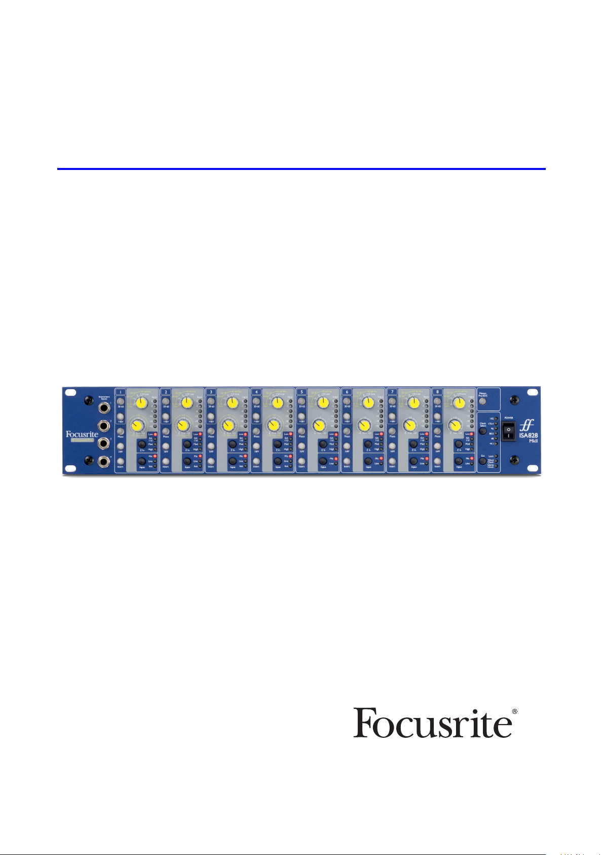
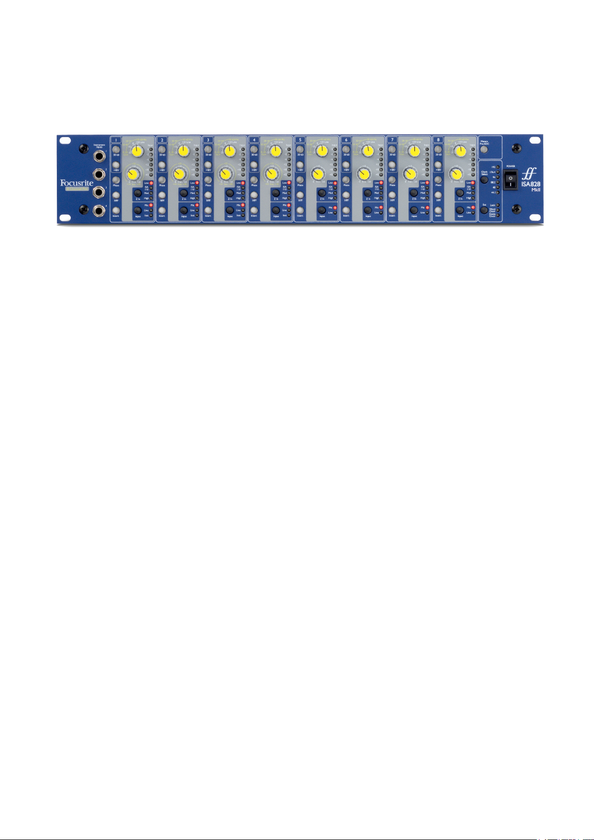
Thank you for purchasing the Focusrite ISA 828 MkII.
The ISA 828 MkII is a high quality eight channel microphone preamplifier, which can be used to
record microphone, line-level or instrument sources. Microphones and line-level sources for all
eight inputs are connected via the rear panel, whilst instrument inputs, available on channels 1–4,
can be plugged directly into the front panel jack sockets.
The front panel also features gain and other settings such as phantom power and impedance for
each of the eight analogue inputs. LED metering is provided on each channel in dBFS, to indicate
when the level is reaching the digital clipping point – a dial for calibration is provided on the rear
panel.
To maintain pristine Focusrite quality in the digital domain, an Analogue-to-Digital interface card
may be fitted into the option slot on the rear panel. This provides access to a Dante network and
features AES3, S/PDIF and ADAT signals.
With the A-D card installed, the internal/external clock sample rate and sync source can be selected
using the switches on the front panel.
4
Page 5
ISA 828 MKII CONTROLS AND FEATURES
Front Panel
Input channels 1–8
LED meter
source
Instrument inputs
for channels 1–4
Channel Controls
Selects the high (30-60 dB) mic gain
range for the Gain switch
Applies +48V phantom power to the
mic input XLR
Inverts polarity (Phase) of the
selected input
Applies a 75 Hz high-pass filter
(HPF) to the selected input
Swaps the A-D option card‘s input
between channel out and external
input ‘A-D Input’
A-D option card: clock
and sync selection
10 dB stepped Mic/Line Gain switch
Mic: 0-30 / 30-60 Line: -20 +10
LED meter for signal level at channel
output or external input
Input Trim pot Mic/Line: 0 +20 dB
Instrument: +10 +40 dB
Selects the input impedance (Z In)
for the Mic and Instrument inputs
Input source selection
Power
switch
Input Selection
Each press of the Input button steps through the available input sources: Mic/Line/Instrument for
channels 1–4, Mic/Line for channels 5–8.
Mic Input
The Gain switch sets the mic gain in 10 dB steps. Its range is either 0–30 dB or 30–60 dB when the
30–60 switch is pressed. An additional 0–20 dB of fine gain adjustment is available by using the Trim
control.
To avoid an excessive jump in level, It is recommended that the stepped Gain switch is turned to minimum before
pressing the 30-60 switch.
Before starting a recording, or if used for PA work, set the Trim control to near its centre position. This will allow for
some gradual gain adjustment up or down without the use of the stepped control.
5
Page 6

Channel Controls...
Line Input
The Gain switch sets the gain at between -20 dB and +10 dB in 10 dB steps. Continuous gain adjustment
of up to 20 dB can be added using the Trim control.
Instrument Input
The Instrument inputs are accessed via standard 1/4” mono jacks on the front panel. The level is set
using the Trim control only and is continuously adjustable from +10 dB to +40 dB.
Refer to the appendix on page 12 for connector pinouts.
Z In (Input Impedance)
With Mic input selected, pressing the Z In button steps through the four
transformer preamp input impedance options. The values are shown in the
table.
For additional information on impedance selection see Appendix 2, “Preamp Input
Impedance” on page 14.
Low
ISA 110
Med 2.4 kΩ
High 6.8 kΩ
Mic Impedance
600 Ω
1.4 kΩ
With Instrument input selected, pressing the switch toggles between High and
Low impedance settings, as shown in the lower table.
The Line input impedance is fixed at 10 kΩ and is not affected by the Z In
Low
High 2.4 MΩ
Instrument Impedance
470 kΩ
switch.
+48V
Pressing the +48V button applies phantom power to the Mic input XLR. This switch does not affect
the Line or Instrument inputs.
If you are unsure whether your microphone requires phantom power please refer to its handbook. Certain
microphones (most notably ribbon and unbalanced mics) could be damaged by applying phantom power.
Phase
Pressing Phase inverts the polarity of the selected input. This can be useful when multiple mic are
used in close proximity (ie., on a drum kit).
HPF (High-Pass Filter)
Pressing HPF inserts the 18 dB/octave 75 Hz high-pass filter into channel path; it is applied to
whichever input is selected.
The HPF is useful for removing any unwanted low frequencies, eg., rumble transmitted through oor mounted
mic stands, etc.
Insert
Pressing a channel’s Insert button switches the A-D option card’s input source from the channel
output to the external input – ie., the same channel in the ‘A-D Inputs’ connector.
The channel’s output is unaffected, allowing its signal to be processed externally and then returned
to the A-D card for conversion.
The return signal levels can monitored on the channel LED meters when the Meters Pre A-D switch is pressed
– see Channel Meters on the next page.
6
Page 7

Channel Meters
The LED meters can be switched to display signal level at two different audio paths,
determined by the setting of the Meters Pre A-D switch on the front panel:
• Meters Pre A-D switch OFF – LEDs show the signal at the channel output. This is
the default setting and shows the level being sent to external recorders/outboard
effects.
• Meters Pre A-D switch ON – LEDs now show the signal level received at the A-D
Input connector on the rear panel. This mode is useful when the A-D option card is
installed and allows the incoming signals to be monitored before being converted
by the digital card.
The LED meter scale is in dBFS, ie., the dB level relative to maximum output (reached
when the red ‘0’ LED illuminates).
The default calibration for the meters is for ‘0’ to indicate a signal level of 22 dBu (which is
the A-D card’s maximum input level). See Meter Calibration below.
Meter Calibration
The signal level at which 0 dBFS is displayed can be adjusted by using the Meter Trim
control on the rear panel.
The default setting of 0 dBFS = 22 dBu occurs when the knob is in its central, detent
position – to correspond with the maximum input level of the A-D card.
Rotating the Meter Trim knob will set the value at between 0 dBFS = 15 dBu (fully
anticlockwise) and 0 dBFS = 26 dBu (fully clockwise).
7
Page 8

Rear Panel
Analogue
outputs 1-8
Line input jacks
1-8
Mic input XLRs
1-8
Mains
inlet
Slot for A-D
option card
A-D external
inputs 1-8
Meter Trim
control
AC Mains Inlet
Standard IEC receptacle for AC mains. ISA 828 MkII features a ‘Universal’ PSU, enabling it to operate
on any supply voltage between 100 V and 240 V AC.
Microphone Inputs
Eight latching XLR-3 female connectors.
Line Inputs
Eight balanced 1/4” TRS jack sockets.
Analogue Outputs
Channel outputs 1–8 on DB25 female connector. These outputs are linked internally to the A-D option
card inputs, except when the Insert switches are pressed.
A-D inputs
Eight analogue inputs to the A-D option card on DB25 female connector. Inputs are enabled individually
by pressing channel Insert switches.
Both DB25 connectors are wired according to the AES59 Standard (also known as the TASCAM Analogue
standard). Refer to the Appendix on page 12 for connector pinouts.
Meter Trim
Allows the channel LED meter reading at full scale to be adjusted between 15 dBu and 26 dBu. At the
central detented position the reading will be 22 dBu, which matches the maximum input level of the
A-D card. Also see Meter Calibration on page 7.
A-D Option Card Slot
Slot for ISA ADN8 analogue to digital conversion card. The card allows audio channels from the ISA
828 MkII to be added to a Dante network. It also provides AES3, S/PDIF and ADAT signals.
See the following page for A-D card details.
8
Page 9

A-D Option Card
The optional ISA ADN8 A-D card can be retrofitted to an ISA 828 MkII at any time. Engineering
experience is not required as the card can easily be installed by the user.
Note that the ISA 828 MkII does not support the earlier ISA 8-Channel A-D card.
Once fitted, configuration of the card is carried out over the network using either RedNet Control or
the Dante Controller software application.
The tting instructions and network software applications are included with the A-D card option.
Word Clock – Input
Allows the card to be synchronised to an external Word Clock source via the BNC connector.
Word Clock – Output
Provides an output of the external Word Clock source connected at the “Word Clock In” BNC connector
or, transmits the internal sample frequency of the A-D card.
• When the ISA 828 MkII is being used as a slave device within a larger digital system, the Word
Clock Out connector can be used to pass on the external word clock signal to the next device.
• When the unit is not slaved to another device and is in Internal Clock mode, the Word Clock
Out connector outputs the sample frequency selected on the ISA 828 MkII front panel.
Primary Network Port
Latching RJ45 connector for the Dante network. Use standard Cat 5e or Cat 6 network cable to
connect to a local Ethernet switch to connect the ISA ADN8 to the Dante network. Adjacent to each
network socket are LEDs which illuminate to indicate a valid network connection and network activity.
Secondary Network Port
Secondary Dante network connection where two independent Ethernet links are being used
(Redundant mode) or an additional port on an integral network switch on the primary network
(Switched mode).
ADAT I/O 1 and 2
Two independent 8-channel ADAT optical inputs and outputs using standard TOSLINK connectors.
AES3 Outputs 1-8
Eight AES3 outputs on DB25 connector.
See Appendix 1 on page 13 for connector pinouts.
See Appendix 3 on page 16 for Pro Tools interfacing information.
9
Page 10

A-D Option Card...
A-D Card Clock and Sync Switches
Clock select
Allows the user to select the internal sample frequency: 44.1kHz, 48kHz, 88.2kHz,
96kHz, 176.4kHz, or 192kHz.
Ext
Allows the ISA ADN8 A-D card to be slaved to an external Word Clock source. Press the
switch to toggle between standard and Dante clock.
Lock LED
Indicates that the unit is successfully synchronised to the external Word Clock.
10
Page 11

PHYSICAL CHARACTERISTICS
325.0mm / 12.8”
465.0mm / 18.3”
63.6mm / 2.5”
Case dimensions are illustrated in the diagram above.
ISA 828 MkII requires 2U of vertical rack space. Allow an additional 75mm of rack depth behind the
unit to allow for cables. ISA 828 MkII weighs 7.05 kg and for installations in a fixed environment (eg.,
a studio rack), the front-panel rack mountings* will provide adequate support. However, if the unit
is to be used in a mobile situation (eg., flight-cased for touring, etc.), it is recommended that side
support rails or shelves are used within the rack.
*Always use M6 bolts and cage nuts specically designed for 19” equipment racks. An Internet search using the
phrase “M6 cage nuts“ will reveal suitable components.
Cooling vents are provided at each side; ensure that when mounted in a rack these vents are
not obstructed. Do not mount the unit immediately above any other equipment which generates
significant heat, for example, a power amplifier.
Note. The maximum operating environmental temperature is 40°C / 104°F.
Power Requirements
ISA 828 MkII is mains powered and incorporates a ‘Universal’ power supply which can operate on
any AC mains voltage from 100 V to 240 V. The AC connection is via a standard 3-pin IEC connector
on the rear panel.
A mating IEC cable is supplied with each unit – this should be terminated with a mains plug of the
correct type for your country.
Power consumption for ISA 828 MkII is 35 W.
Please note that there are no fuses or other user-replaceable components of any type in any unit.
Please refer all servicing issues to the Customer Support Team (see “Customer Support and Unit Servicing”
on page 19).
11
Page 12

APPENDICES
1. Connector Pinouts
Mic Input
Connector: XLR-3 female
Line Input
Connector: Balanced (TRS) 1/4” Jack socket
Tip Ring Sleeve
Instrument Input
Connector: Unbalanced (TS) 1/4” Jack socket
Tip Sleeve
Line Outputs / A-D Inputs
Connector: DB25 female (AES59 analogue)
113
25 14
Screw binding-posts use the standard UNC 4/40 thread
Pin
1 Screen
2 Hot (+ve)
3 Cold (–ve)
Pin
Tip Hot (+ve)
Ring Cold (–ve)
Sleeve Ground
Pin
Tip Hot (+ve)
Sleeve Ground
Pin
1 Channel 8 +
14 Channel 8 –
2 Ground
15 Channel 7 +
3 Channel 7 –
16 Ground
4 Channel 6 +
17 Channel 6 –
5 Ground
18 Channel 5 +
6 Channel 5
19 Ground
7 Channel 4 +
20 Channel 4 –
8 Ground
21 Channel 3 +
9 Channel 3 –
22 Ground
10 Channel 2 +
23 Channel 2 –
11 Ground
24 Channel 1 +
12 Channel 1 –
25 Ground
13 n/c
Signal
Signal
Signal
Signal
12
Page 13

1. Connector Pinouts...
1
8
ISA ADN8 Option Card:
AES3 Outputs
Connector: DB25 female (AES59 digital)
113
25 14
Screw binding-posts use the standard UNC 4/40 thread
Pin Signal
1 Out channels 7/8 +
14 Out channels 7/8 –
2 Ground
15 Out channels 5/6 +
3 Out channels 5/6 –
16 Ground
4 Out channels 3/4 +
17 Out channels 3/4 –
5 Ground
18 Out channels 1/2 +
6 Out channels 1/2
19 Ground
7 In channels 7/8 +
20 In channels 7/8 –
8 Ground
21 In channels 5/6 +
9 In channels 5/6 –
22 Ground
10 In channels 3/4 +
23 In channels 3/4 –
11 Ground
24 In channels 1/2 +
12 In channels 1/2 –
25 Ground
13 n/c
Network 1 & 2
Connector type: RJ-45 receptacle
ADAT Optical Interface
Connector: TOSLINK
Word Clock In & Out
Connector: BNC 75Ω
Pin Cat 5/6 Core
1 White + Orange
2 Orange
3 White + Green
4 Blue
5 White + Blue
6 Green
7 White + Brown
8 Brown
13
Page 14

Appendices...
2. Preamp Input Impedance
A major element of the sound of a mic pre is related to the interaction between the specific microphone
being used and the type of mic preamp interface technology it is connected to. The main area in which
this interaction has an effect is the level and frequency response of the microphone, as follows:
Level
Professional microphones tend to have low output impedances and so more level can be achieved by
selecting the higher impedance positions of the ISA 828 MkII mic preamp.
Frequency response
Microphones with defined presence peaks and tailored frequency responses can be further enhanced
by choosing lower impedance settings. Choosing higher input impedance values will tend to
emphasise the high frequency response of the microphone connected, allowing you to get improved
ambient information and high end clarity – even from average-performance microphones. Various
microphone/ISA 828 MkII preamp impedance combinations can be tried to achieve the desired
amount of colouration for the instrument or voice being recorded. To understand how to use the
impedance selection creatively, it may be useful to read the following section on how the microphone
output impedance and the mic preamp input impedance interact.
Impedance Setting – Quick Guide
In general the following selections will yield the following results:
High mic preamp impedance settings:
• Will generate more overall level
• Will tend to make low- and mid-frequency response of the microphone flatter
• Will improve high-frequency response of the microphone.
Low preamp impedance settings:
• Will reduce the microphone output level
• Will tend to emphasise the low- and mid-frequency presence peaks and
resonant points of the microphone
Switchable Impedance – In Depth Explanation
Dynamic Moving Coil and Condenser Microphones
Almost all professional dynamic and condenser microphones are designed to have a relatively low
nominal output impedance of between 150 Ω and 300 Ω when measured at 1 kHz. Microphones are
designed to have such low output impedance because the following advantages result:
• They are less susceptible to noise pickup
• They can drive long cables without high frequency roll-off due to cable capacitance
The side-effect of having such low output impedance is that the mic preamp input impedance
has a major effect on the output level of the microphone. Low preamp impedance loads down the
microphone output voltage, and emphasizes any frequency-related variation in microphone output
14
Page 15

2. Pre Amp Impedance...
impedance. Matching the mic preamp resistance to the microphone output impedance (eg., making
a preamp input impedance 200 Ω to match a 200 Ω microphone) still reduces the microphone output
and signal to noise ratio by 6 dB, which is undesirable.
To minimise microphone loading, and to maximise signal to noise ratio, preamps have traditionally
been designed to have an input impedance about ten times greater than the average microphone,
around 1.2 kΩ to 2 kΩ. (The original ISA 110 preamp design followed this convention and has an
input impedance of 1.4 kΩ at 1 kHz.) Input impedance settings greater than 2 kΩ tend to make the
frequency-related variations of microphone outputs less significant than at low impedance settings.
Therefore high input impedance settings yield a microphone performance that is flatter in the low
and mid frequency areas and boosted in the high frequency area when compared to low impedance
settings.
Ribbon Microphones
The impedance of a ribbon microphone is worthy of special mention, as this type of microphone is
affected enormously by preamp impedance. The ribbon impedance within this type of microphone is
incredibly low, around 0.2 Ω, and requires an output transformer to convert the extremely low voltage
it can generate into a signal capable of being amplified by a preamp. The ribbon microphone output
transformer requires a ratio of around 1:30 (primary:secondary) to increase the ribbon voltage to
a useful level, and this transformer ratio also has the effect of increasing the output impedance of
the mic to around 200 Ω at 1 kHz. This transformer impedance, however, is very dependent upon
frequency - it can almost double at some frequencies (known as the resonance point) and tends
to roll off to very small values at low and high frequencies. Therefore, as with the dynamic and
condenser microphones, the mic preamp input impedance has a massive effect on the signal levels
and frequency response of the ribbon microphone output transformer, and thus the ‘sound quality’
of the microphone. It is recommended that a mic preamp connected to a ribbon microphone should
have an input impedance of at least 5 times the nominal microphone impedance.
For a ribbon microphone impedance of 30 Ω to 120 Ω, the input impedance of 600 Ω (Low) will work
fine. For 120 Ω to 200 Ω ribbon microphones, the input impedance setting of 1.4 kΩ (ISA 110) is
recommended.
15
Page 16

Appendices...
3. Pro Tools Interfacing
• Analogue out to Pro Tools | HD
ISA 828 MkII
Red 16Line
DB25 male – DB25 male 8ch analogue
Pro Tools interface
• Dante to Pro Tools | HD
ISA 828 MkII
Dante Network
RedNet HD32R
RJ45 – RJ45 network
Pro Tools interface
16
Page 17

PERFORMANCE AND SPECIFICATIONS
Microphone Inputs
All measurements taken at minimum gain, Z In: medium, unless otherwise stated. Measurements taken at the analogue outputs
Gain Range
Maximum Input Level
Input Impedance Transformer balanced, Low: 600 Ω, ISA 110: 1.4 kΩ, Medium: 2.4 kΩ, High: 6.8 kΩ
Signal-to-Noise Ratio 122 dB ‘A’-Weighted (typical), maximum gain
Frequency Response 20 Hz – 20 kHz ± 0.2 dB | 10 Hz – 110 kHz ± 1.5 dB
THD + N -92 dB (0.0025%) @ -1 dBr
High-Pass Filter
EIN <-123 dBu ‘A’-Weighted (typical), maximum gain
Common Mode Rejection
Ratio
0 to 30 dB or 30 to 60 dB (with ‘30-60’ switch enabled), in 10 dB steps,
plus 0 to 20 dB of continuous trim
+7 dBu
75 Hz knee frequency, 18 dB/octave, switchable per channel
-93 dB @ 1kHz
Line Inputs
All measurements taken at minimum gain, Z In: Low, unless otherwise stated, RS = 50 Ω. Measurements taken at the analogue outputs
Gain Range
Maximum Input Level +25 dBu
Input Impedance Electronically balanced 10 kΩ
-20 to +10 dB in 10 dB steps, plus 0 to 20 dB continuous trim
Signal-to-Noise Ratio 122 dB ‘A’-Weighted (typical), maximum gain
Frequency Response 20 Hz – 20 kHz ± 0.1 dB | 10 Hz – 122 kHz ± 3 dB unity gain
THD + N -91 dB (0.0028%) @ -1 dBr
High-Pass Filter
Common Mode Rejection
Ratio
75 Hz knee frequency, 18 dB/octave, switchable per channel
-65 dB @ 1 kHz
Instrument Inputs
All measurements taken at minimum gain, Z In: Low, unless otherwise stated, RS = 600 Ω. Measurements taken at the analogue outputs
Gain Range
Maximum Input Level
Input Impedance
Signal-to-Noise Ratio
Frequency Response 20 Hz – 20 kHz ±0.1 dB | 10 Hz – 110 kHz ± 1.2 dB
THD + N
High-Pass Filter
+10 to +40 dB continuous, using Trim pot
+18 dBu
Low: 470 kHz, High: 2.4 MΩ
100 dB ‘A’-Weighted
-83 dB (0.0071%) @ -1 dBFS
75 Hz knee frequency, 18 dB/octave, switchable per channel
17
Page 18

Performance and Specications . . .
Connectivity
Front panel
Instrument inputs 4 x 1/4” mono jack
Rear Panel
Microphone inputs
Line level inputs
Line level outputs
A-D inputs
8 x XLR-3 female
8 x 1/4” balanced jack
1 x DB25 female (AES59 Tascam Analogue)
1 x DB25 female (AES59 Tascam Analogue)
Digital Card Slot
Compatible card
ISA ADN8
Crosstalk
All measurements taken at minimum gain, Z In: Medium
Microphone Inputs -60 dB, 20 Hz – 20 kHz
Line Inputs -80 dB, 20 Hz – 20 kHz
Instrument Inputs -80 dB, 20 Hz – 20 kHz
Dimensions
Height 88mm / 3.46”
Width 482mm / 18.98”
Depth 325mm / 12.8”
Weight
Weight
7.05 kg / 15.55 lbs
Power
PSU
Consumption
1 x Internal, 100 – 240 V, 50 / 60 Hz
35 W.
Environmental
Operating Temperature
40°C / 104°F Maximum ambient operating temperature
18
Page 19

Focusrite RedNet Warranty and Service
All Focusrite products are built to the highest standards and should provide reliable performance for
many years, subject to reasonable care, use, transportation and storage.
Very many of the products returned under warranty are found not to exhibit any fault at all. To
avoid unnecessary inconvenience to you in terms of returning the product please contact Focusrite
support.
In the event of a Manufacturing Defect becoming evident in a product within 12 months from the date
of the original purchase Focusrite will ensure that the product is repaired or replaced free of charge.
A Manufacturing Defect is defined as a defect in the performance of the product as described and
published by Focusrite. A Manufacturing Defect does not include damage caused by post-purchase
transportation, storage or careless handling, nor damage caused by misuse.
Whilst this warranty is provided by Focusrite the warranty obligations are fulfilled by the distributor
responsible for the country in which you purchased the product.
In the event that you need to contact the distributor regarding a warranty issue, or an out-of-warranty
chargeable repair, please visit: www.focusrite.com/distributors
The distributor will then advise you of the appropriate procedure for resolving the warranty issue.
In every case it will be necessary to provide a copy of the original invoice or store receipt to the
distributor. In the event that you are unable to provide proof of purchase directly then you should
contact the reseller from whom you purchased the product and attempt to obtain proof of purchase
from them.
Please do note that if you purchase a Focusrite product outside your country of residence or business
you will not be entitled to ask your local Focusrite distributor to honour this limited warranty,
although you may request an out-of-warranty chargeable repair.
This limited warranty is offered solely to products purchased from an Authorised Focusrite Reseller
(defined as a reseller which has purchased the product directly from Focusrite Audio Engineering
Limited in the UK, or one of its Authorised Distributors outside the UK). This Warranty is in addition
to your statutory rights in the country of purchase.
Registering Your Product
For access to Dante Virtual Soundcard, please register your product at: www.focusrite.com/register
Customer Support and Unit Servicing
You can contact our dedicated RedNet Customer Support team free of charge:
Email: proaudiosupport@focusrite.com
Phone (UK): +44 (0)1494 836384
Phone (USA): +1 (310) 450-8494
Troubleshooting
If you are experiencing problems with your ISA 828 MkII, we recommend that in the first instance, you
visit our Support Help Centre at: https://pro.focusrite.com/help-centre
19
 Loading...