

Page 1
MIXMASTER™DIGITAL OPTION INSTALLATION GUIDE
MixMaster
™
Digital 24/96 Output Kit
The kit should contain:-
Qty Description
1 24/96 Analogue to digital converter card
4 Cross head screws,for XLR,SPDIF and
EXT WCLK INPUT connectors
2 Support pillars
Tools Required:-
No.1 crosshead screw driver,Pozihead preferred.
Installation Instructions
WARNING!
THE MIXMASTER MODULE SHOULD BE
DISCONNECTED FROM THE A.C. POWER BEFORE
A TTEMPTING TO CARR Y OUT THE FOLLOWING
INSTRUCTIONS.
ALLOW THE MIXMASTER MODULE TO COOL
BEFORE STARTING INSTALLATION OF THE
DIGITAL OPTION.
ANTI-STATIC PRECAUTIONS SHOULD BE TAKEN
WHEN HANDLING THE CARD OUTSIDE OF ITS
ANTI-STATIC BAG;ONLY HANDLE THE CARD BY
GRIPPING THE CARD BY ITS EDGES AND AVOID
TOUCHING ANY OF THE COMPONENT PARTS
OTHER THAN THE CABLE AND CONNECTORS.
PLACE THE UNIT ON A CLEAN,FLAT SURFACE.
Top Lid Removal
Remove the 12 crosshead screws fixing the top lid to the top
and sides of the module.
Digital
Option
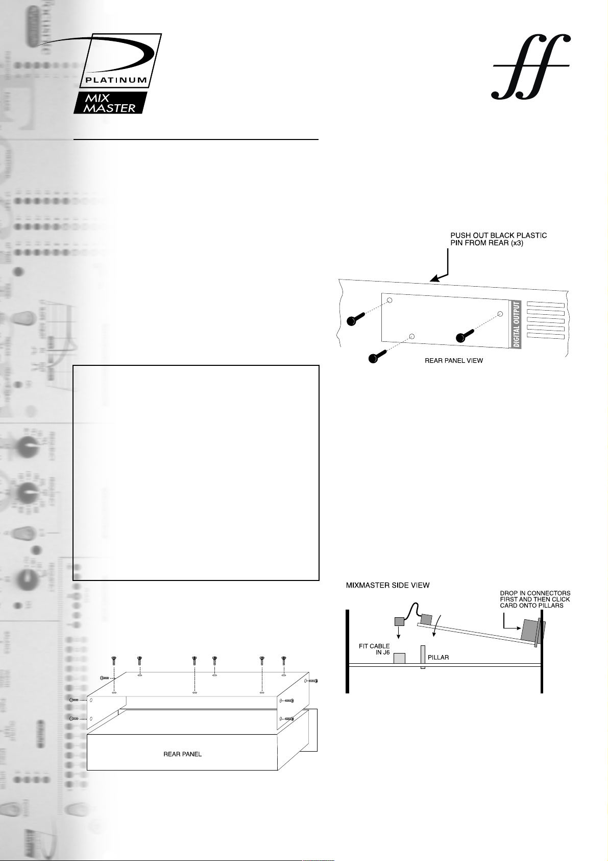
Digital Option Cover Removal
The rear panel digital connector area is accessed by removing
the small rear cover plate next to “DIGITAL OUTPUT”. The
plate is removed by pushing out,from inside of the module,the
3 black plastic retaining pins.Once removed these retaining pins
are no longer required.
Installing Digital Card
The digital card is mounted in place using the digital connector
fixings and the two white plastic support pillars which should be
fitted first into the two slots on the main circuit board (next to
C322/C172).
Now slide the digital card towards the rear of the unit such that
the connectors pass through the rear panel and the rear
mounting holes line up with the pillars previously mounted on
the main circuit board.
Secure the digital card in position by gently clicking onto the
pillars,taking care not to place excessive pressure on the main
circuit board.
Page 2
Focusrite Audio Engineering Ltd, Lincoln Road, High Wycombe, Bucks HP12 3FX England
Tel: +44 (0)1494 462246 FAX: +44 (0)1494 459920
e-mail: sales@focusrite.com www.focusrite.com
Focusrite
audio engineering
Installing Digital Card (cont)
Once the card is locked into place,with the connectors firmly up
against the rear panel,the connectors and earthing cable can be
screwed into place as follows:-
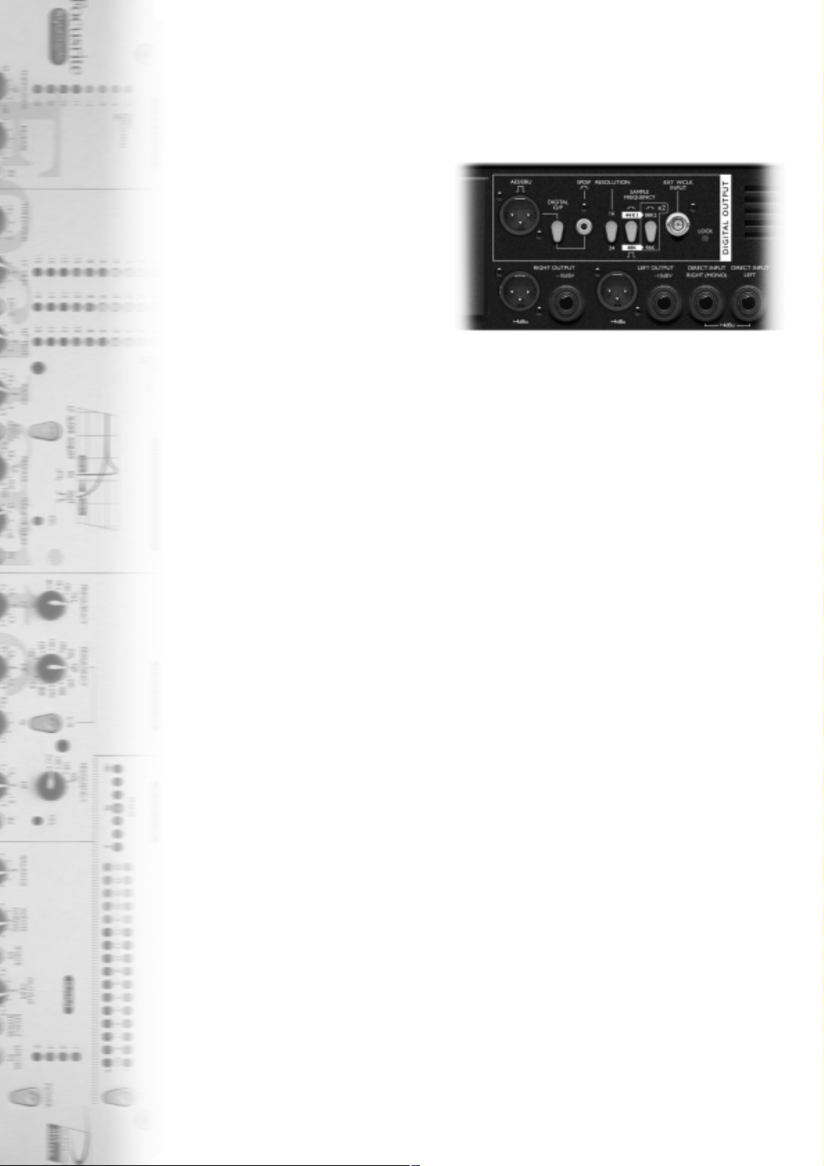
Connector Fixing
AES/EBU 2 cross head screws
SPDIF 1 cross head screw
EXT WCLK INPUT 1 cross head screw, washer and nut
Once the card has been secured in place the digital card ribbon
cable can be connected to the adjacent plug,labelled “J6”,on the
MixMaster circuit board.The connector should be pressed firmly
down in place to ensure good contact.
Replacing the Lid
The lid should be refitted so that the single screw holes on the
side are towards the front of the module and the pairs of screw
holes are towards the back.Once the lid has been positioned
correctly replace the 12 crosshead screws on the top and sides
of the module.
The installation is now complete and the module can be
reconnected to the A.C. power.
Notes:
1. The “DIGITAL O/P” switch should be pressed when using
the SPDIF output. The function of the switch is to correctly
match the signal levels between the sending and receiving
equipment.
2. The digital card is not designed for the AES and SPDIF
outputs to be used simultaneously as this may damage the
digital card.
3. When syncing to an external clock the sampling frequency
should be set to match between the two pieces of
equipment.
 Loading...