

Page 1
E
N
G
L
I
S
H
E
S
P
A
Ñ
O
L
I
T
A
L
I
A
N
O
F
R
A
N
Ç
A
I
S
D
E
U
T
S
C
H
1
English
Inhaltsverzeichnis
Wichtige Sicherheitshinweise . . . . .2
Signalanschlüsse . . . . . . . . . . . . . .4
Block Diagram . . . . . . . . . . . . . . .5
Einleitung . . . . . . . . . . . . . . . . .15
Anschlüsse und Schalter auf der
Rückseite . . . . . . . . . . . . . . . . . .15
Bedienelemente . . . . . . . . . . . . .16
Stereo-Expander . . . . . . . . . . .16
Stereo Spectral Compressor . . .16
Stereo-Equaliser . . . . . . . . . . .17
Output . . . . . . . . . . . . . . . . . .18
Haupt-Pegelanzeige . . . . . . . .18
Direkteingang . . . . . . . . . . . . .18
Der digitale Ausgang . . . . . . . .19
Einsatzbereiche
/Anwendungsbeispiele . . . . . .19
Technische Daten . . . . . . . . . . . .21
Distributoren . . . . . . . . . . . . . . .47
Deutsch
Table des matières
Consignes de sécurité . . . . . . . . . .3
Connexions . . . . . . . . . . . . . . . . .4
Block Diagram . . . . . . . . . . . . . . .5
Introduction . . . . . . . . . . . . . . .22
Connexions et réglages en face
arriére . . . . . . . . . . . . . . . . . . . . .22
Fonctions et commandes . . . . . . .23
Expanseur stéréo . . . . . . . . . . .23
Compresseur multibande stéréo
.23
Correcteur stéréo . . . . . . . . . .24
Sortie . . . . . . . . . . . . . . . . . . .25
Afficheurs de niveaux . . . . . . .25
Entree directe . . . . . . . . . . . . .25
Sortie numérique . . . . . . . . . .26
Applications . . . . . . . . . . . . . .26
Quelques conseils pour le Home
Mastering . . . . . . . . . . . . . . . .28
Caractéristiques . . . . . . . . . . . . . .30
Distributeurs . . . . . . . . . . . . . . . .47
Français
Indice
Importanti Istruzioni per
la Sicurezza . . . . . . . . . . . . . . . . . .3
Connessioni . . . . . . . . . . . . . . . . .4
Schema a Blocchi . . . . . . . . . . . . .5
Introduzione . . . . . . . . . . . . . . . .31
Pannello Posteriore . . . . . . . . . . .31
Funzioni e Controlli . . . . . . . . . .32
Stereo Expander . . . . . . . . . . .32
Stereo Spectral Compressor . . .32
Stereo Equaliser . . . . . . . . . . .33
Output . . . . . . . . . . . . . . . . . .34
Sezione Strumenti . . . . . . . . . .34
Direct Input . . . . . . . . . . . . . .34
Digital Output . . . . . . . . . . . .35
Applicazioni . . . . . . . . . . . . . .35
Specifiche Tecniche . . . . . . . .37
Elenco dei Distributori . . . . . . . .47
Italiano
Contenido
Instrucciones Importantes de
Seguridad . . . . . . . . . . . . . . . . . . .3
Puesta en Marcha . . . . . . . . . . . . .4
Diagrama de Bloques . . . . . . . . . . .5
Introducción . . . . . . . . . . . . . . .38
Conexiones y Conmutadores
del Panel Trasero . . . . . . . . . . . . .38
Prestaciones y Controles . . . . . . .39
Stereo Expander . . . . . . . . . . .39
Stereo Spectral Compressor . . .39
Stereo Equaliser . . . . . . . . . . .40
Output . . . . . . . . . . . . . . . . . .41
Medidores . . . . . . . . . . . . . . .41
Direct Input . . . . . . . . . . . . . .41
Digital Output . . . . . . . . . . . .42
Aplicaciones . . . . . . . . . . . . . .42
Consejos en Masterización . . .44
Especificaciones . . . . . . . . . . . . . .46
Lista de Distribuidores . . . . . . . . .47
Español
E
N
G
L
I
S
H
E
S
P
A
Ñ
O
L
I
T
A
L
I
A
N
O
F
R
A
N
Ç
A
I
S
D
E
U
T
S
C
H
Page 2

2
Important Safety Instructions / Wichtige Sicherheitshinweise
apertures.
on the unit.
conditions:
If the power cord or plug is damaged; if liquid has entered the unit; if the unit has
been dropped or the case damaged; if the unit does not operate normally or exhibits a
distinct change in performance. Adjust only those controls that are covered by the
operating instructions.
plug has two blades with one wider than the other. A grounding type plug has two
blades and a third grounding prong. The wider blade or the third prong are provided
for your safety. When the plug provided does not fit into your outlet, consult an
electrician for replacement of the obsolete outlet.
UNDER NO CIRCUMSTANCES SHOULD THE MAINS EARTH BE
DISCONNECTED
FROM THE MAINS LEAD.
Wichtige Sicherheitshinweise
Lesen Sie bitte alle folgenden Anweisungen und bewahren Sie diese für spätere Verwendung auf.
Beachten Sie alle auf dem Gerät angebrachten Warnhinweise und Anweisungen.
● Decken Sie die Lüftungsschlitze auf der Rückseite nicht ab. Führen Sie keine Objekte durch die
Öffnungen in das Gerät ein.
● Verwenden Sie keine beschädigten oder durchgescheuerten Netzkabel.
● Ziehen Sie das Netzkabel, bevor Sie das Gerät reinigen. Verwenden Sie zum Reinigen nur ein
feuchtes Tuch. Gießen Sie keine Flüssigkeit auf das Gerät.
● Bitte ziehen Sie in den folgenden Fällen das Netzkabel und übergeben das Gerät zur Wartung an
hierfür qualifiziertes Personal:
● Wenn das Netzkabel oder der Netzstecker beschädigt ist; wenn Flüssigkeit in das Gerät
eingedrungen ist, wenn das Gerät aus großer Höhe gefallen ist oder das Gehäuse beschädigt wurde;
wenn das Gerät nicht mehr einwandfrei funktioniert oder die Leistung sich in erheblichem Umfang
geändert hat. Verändern Sie nur solche Einstellungen, die in der Bedienungsanleitung beschrieben
sind.
● Manipulieren Sie nicht den Netzstecker dieses Gerätes. Ein polarisierter Stecker hat zwei Kontakte,
von denen einer länger ist als der andere. Ein geerdeter Stecker hat zwei Kontakte sowie einen
dritten Erdungsanschluss. Der längere Kontakt beziehungsweise der Erdungsanschluss dienen Ihrer
Sicherheit. Wenn der Stecker an dem mit diesem Gerät gelieferten Kabel nicht zur Steckdose am
Einsatzort passt, lassen Sie die entsprechende Steckdose durch einen Elektriker ersetzen.
ACHTUNG: DAS GERÄT MUSS ÜBER DAS NETZKABEL GEERDET SEIN.
AUF KEINEN FALL SOLLTE DIE ERDUNG VOM NETZKABEL GETRENNT
WERDEN.
Dieses Gerät kann über den gesamten auf der Rückseite angegebenen Spannungsbereich betrieben
werden. Überprüfen Sie vor dem Anschließen des Gerätes an das Stromnetz, ob eine geeignete
Spannung und die erforderliche Sicherung vorhanden sind. Ändern Sie nicht die Netzspannung, solange
das Gerät mit dem Stromnetz verbunden ist.
Um das Risiko eines Brandes zu vermeiden, sollten Sie die Hauptsicherung im Bedarfsfall nur durch eine
geeignete Sicherung ersetzen. Die entsprechenden Werte sind auf der Rückseite des Gerätes angegeben.
Das Netzteil des Gerätes enthält keine vom Anwender zu wartenden Teile. Bitte überlassen Sie alle
Wartungsarbeiten einem von Ihrem Focusrite-Händler beauftragten, qualifizierten Servicetechniker.
E
N
G
L
I
S
H
D
E
U
T
S
C
H
Page 3

3
Consignes de sécurité/Importanti Istruzioni per la Sicurezza/Instrucciones Importantes de Seguridad
E
S
P
A
Ñ
O
L
I
T
A
L
I
A
N
O
F
R
A
N
Ç
A
I
S
VEILLEZ À CE QUE LE CÂBLE DE MASSE DU
Instrucciones Importantes de Seguridad
Deben leerse todas las instrucciones y guardarlas para futura
referencia. Sigan los consejos e indicaciones rotulados en la unidad.
● No obstruir las salidas de ventilación del panel trasero. No
introducir objetos por las aberturas.
● No utilizar cables de conexión viejos o dañados.
● Desenchufar la unidad antes de limpiarla. Limpiarla con un trapo
húmedo exclusivamente. No verter líquidos en la unidad.
● Desenchufar la unidad y dirigirse a personal técnico autorizado
en las siguientes situaciones:
Si el cable de alimentación o el conector están dañados; si a la
unidad le ha entrado líquido; si la unidad se ha caído o el
embalaje está dañado; si la unidad no funciona correctamente
o muestra diferentes características a las reseñadas. Manipular
exclusivamente los controles que están detallados en el manual
de usuario.
● No modificar la polaridad del conector de alimentación. Para
su seguridad, es mejor dirigirse a un técnico electricista para
cambiar la clavija en el caso de que la suministrada no sea
posible enchufarla a la toma de red eléctrica.
AVISO: LA TOMA DE TIERRA DEL CABLE DE
ALIMENTACION DEBERA ESTAR CONECTADA
BAJO NINGUNA CIRCUNSTANCIA DEBE
DESCONECTARSE LA TOMA DE TIERRA DEL CABLE
La unidad ofrece la posibilidad de operar en diferentes rangos de
tensión eléctrica según se indica en la trasera de la unidad. Es
necesario asegurarse que se ha realizado una selección de tensión
adecuada la del suministro de electricidad antes de conectar la
unidad. No debe modificarse la selección de tensión sin haber
desconectado la unidad anteriormente.
Para evitar la posibilidad de incendio, debe sustituirse el fusible
por otro del mismo valor, según se indica en la trasera.
La fuente de alimentación esta compuesta por elementos no
reparables por el usuario. Para realizar cualquier reparación es
preferible que se dirijan a su distribuidor Focusrite o a un servicio
técnico autorizado
.
Importanti Istruzioni per la Sicurezza
Leggere attentamente le seguenti istruzioni, e seguire con
attenzione i messaggi di sicurezza stampati sull’apparecchiatura.
● Non ostruire i fori di ventilazione del pannello posteriore,
non inserire oggetti attraverso le aperture.
● Non utilizzare cavi di alimentazione danneggiati o logori.
● Disconnettere l’alimentazione in caso di pulizia, da effettuarsi
solo con un panno leggermente inumidito, non spruzzare
liquidi.
● Disconnettere l’unita e riferirsi al centro assistenza qualificato
nei seguenti casi:
se il cavo o la presa di alimentazione sono danneggiati; se del
liquido è penetrato all’interno; se il prodotto è caduto o
risulta esteriormente danneggiato; se non funziona
regolarmente o mostra chiari cambiamenti di prestazioni.
Operare solo sui controlli riportati sul manuale di istruzioni.
● Utilizzare solo cavi provvisti di contatto di terra, se il cavo in
dotazione non fosse compatibile con le vostre prese,
sostituirlo consultando un elettricista.
ATTENZIONE ! QUESTA APPARECCHIATURA
DEVE ESSERE MESSA A TERRA ATTRAVERSO IL
CAVO DI ALIMENTAZIONE
IN NESSUN CASO DEVE ESSERE INTERROTTA LA
CONNESSIONE DI TERRA
L’unità può essere alimentata con diverse tensioni, come
riportato sul pannello posteriore, assicurarsi che la posizione del
selettore, e il fusibile siano appropriati, prima di connettere il
prodotto alla rete. Non agire sul selettore con l’alimentazione
inserita.
Per evitare i rischi di incendio sostituire il fusibile con uno adatto
alla tensione di rete, come riportato sul pannello posteriore..
L’alimentatore interno non contiene parti sostituibili dall’utente,
in caso di guasto, contattare il centro di assistenza attraverso un
rivenditore Focusrite.
Page 4
4
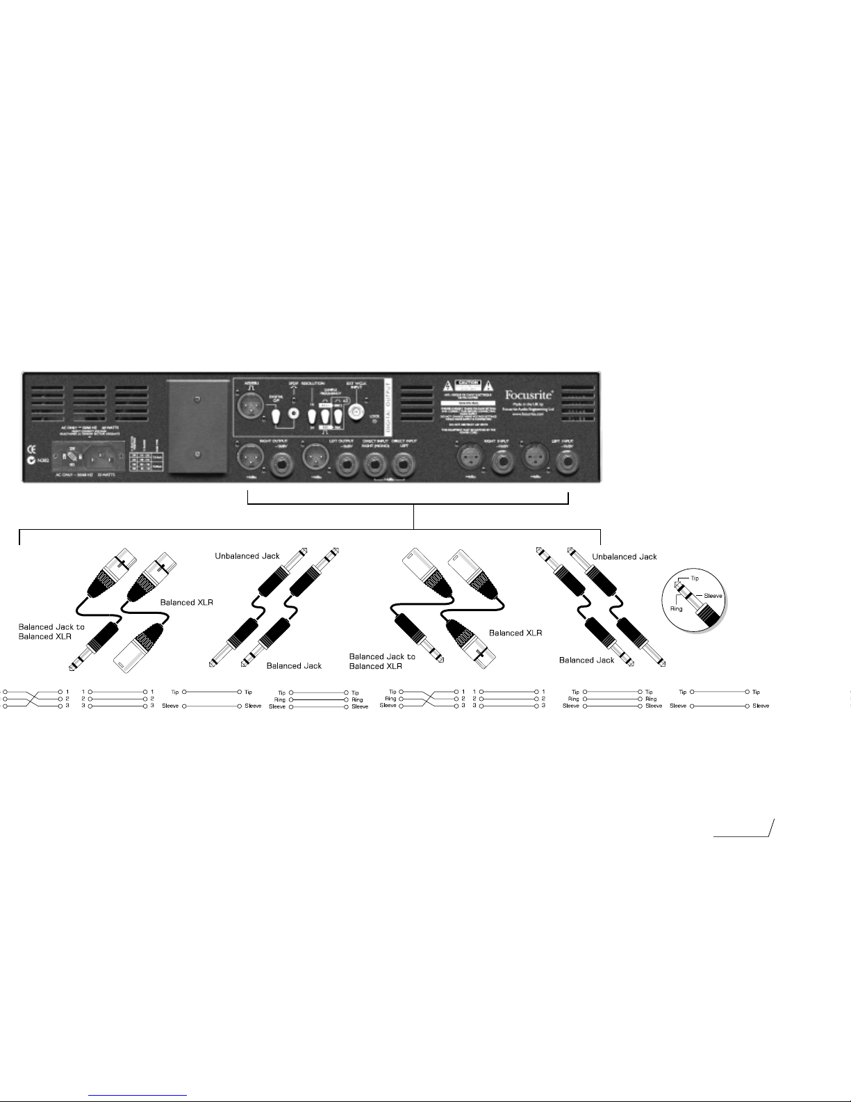
Connecting Up
Page 5
5
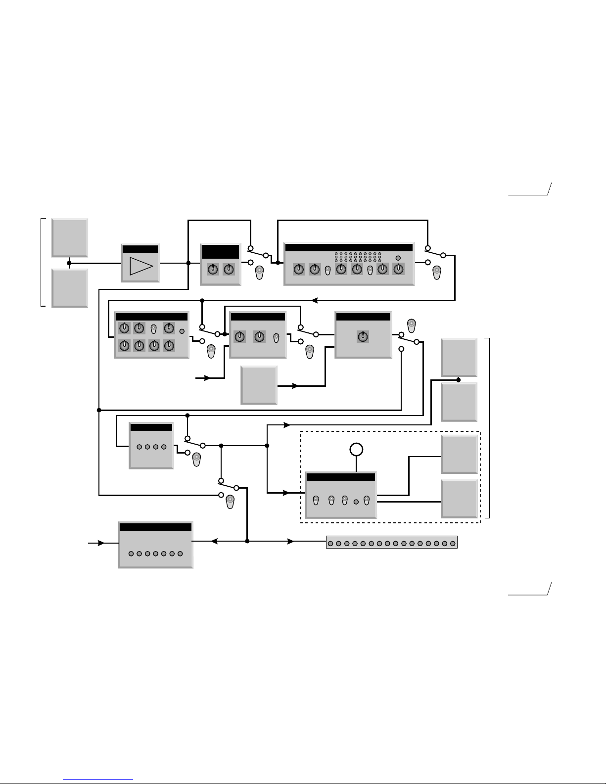
Block Diagram of the MixMaster
INPUT
STEREO
EXPANDER
XLR
OUTPUT
+4dBu
JACK
OUTPUT
-10dBV
IN
Left channel only shown.
Right channel similar
XLR
INPUT
JACK
INPUT
+4dBu
-10dBv
threshold
lock
STEREO SPECTRAL COMPRESSOR
LF trim
HF trim
slow
attack
ratio
release
make up
gain
O/L
IN
freq freq freq
STEREO EQUALISER
LF MF Q HF
x10
O/L
IN
IMAGE CONTROLS
balance width
image in
SUM+OUTPUT TRIM
output trim
IMAGE IN
EFFECT
BYPASS
DIGITAL OUTPUT
88k2/96k
lock
AES/EBU
SPDIF
PHASE METER
-40 -30 -25 -20 -16 -14 -12 -10 -8 -6 -4 -3 -2 -1 0 O/L
I/P
180 90 0
44k1/48k
resolution
digital
o/p
sample
frequency
optional digital output
EXT WCLK
INPUT
from Right channel
Main Bargrah Meter
DIRECT
INPUT
threshold
release
LIMITER
-6 -4 -2 -1
limiter
in
Left channel
RIGHT
INPUT
OUTPUT
Page 6
E
N
G
L
I
S
H
6
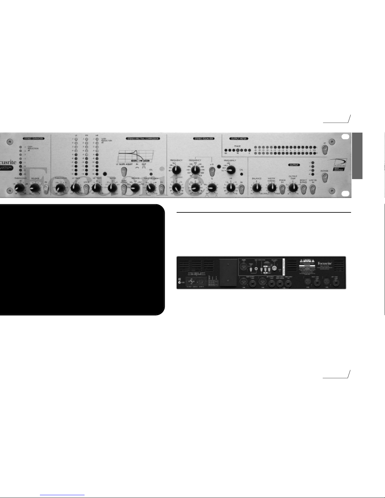
Introduction
Introduction
The MixMaster is an analogue stereo audio processor,
with an optional 24/96 high quality digital output. It
combines a range of specialist tools in one compact
unit, providing the project studio engineer/producer
with really effective and creative control of the output,
maximising signal level and punch in the final mix
without tying up other processors.
The unit comprises a balanced Line Input, Stereo
Expander, Multi-Band Compressor, 3-Band Parametric
EQ, Stereo Image Controller and a Limiter protecting
the 24/96 Digital Output or conventional analogue
outputs.
A pair of stereo Direct Inputs is also included to enable
a separate source to be added to the final mix, just
before the Limiter and outputs.
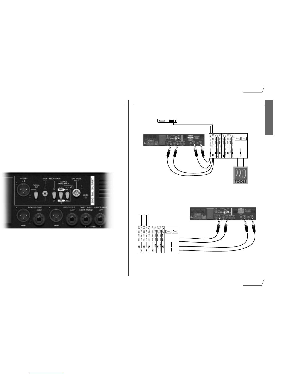
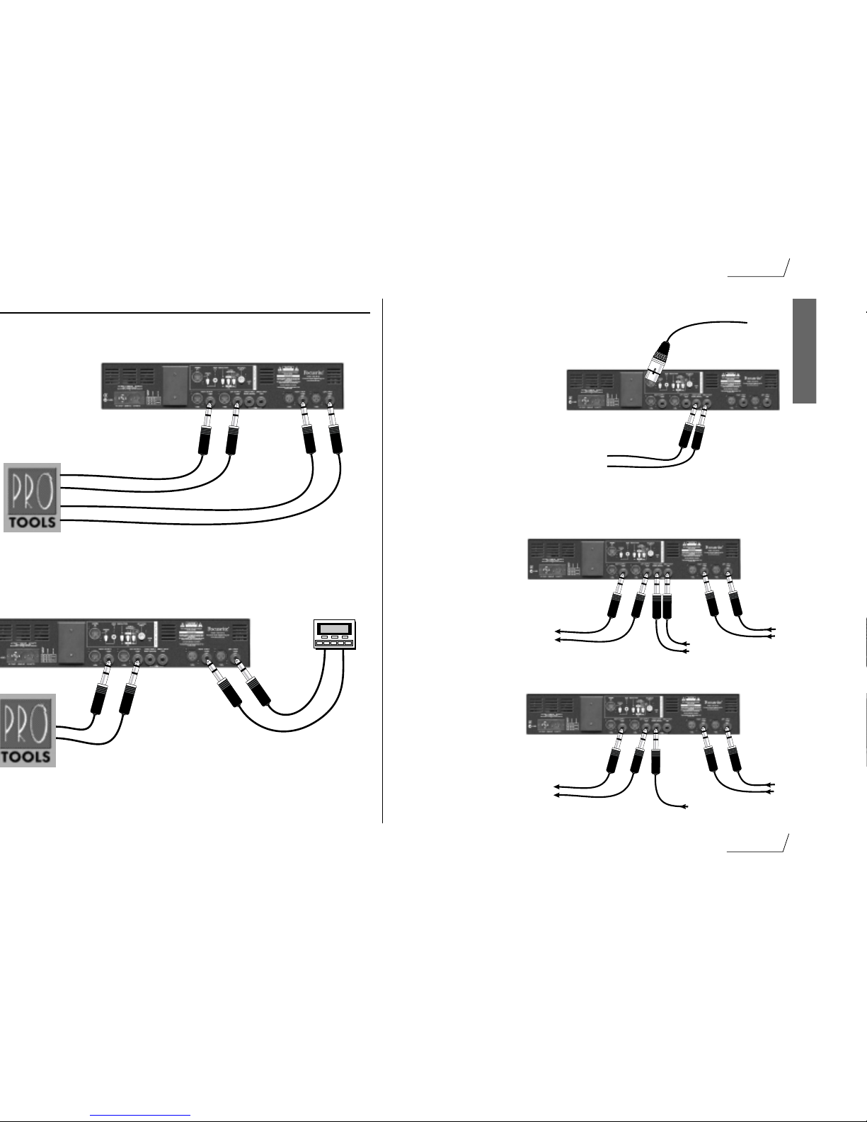
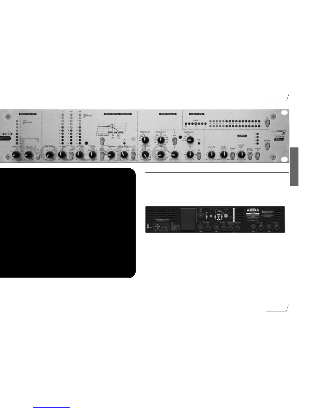
REAR PANEL CONNECTIONS AND SWITCHES
The MixMaster is provided with line level inputs on both XLR and 3 pole 1/4” jack
connectors: inserting a jack cord plug into the jack will override the corresponding XLR. The
nominal sensitivity of the XLR input is +4dBu to match professional equipment with balanced
outputs such as mixing consoles or professional recorders. The jack input has a nominal
sensitivity of -10dBV to match semi-professional or consumer equipment such as CD players,
DAT recorders or sound modules.
A separate stereo direct input is provided at +4dBu on two 1/4” jacks. Mono sources, such as a
microphone preamp output may be fed to both channels by plugging in the Right (Mono)
jack.
Balanced analogue outputs are provided as standard on XLR (+4dBu) or jack (-10dBV) to
match both professional and semi-professional equipment.
In addition to the analogue outputs, a high quality 128 times oversampled stereo digital output
(64 times oversampled at high sample rates) may be fitted as an option. Rear panel switches
select 16 or 24 bit resolution at a sample frequency of 44.1, 48, 88.2 or 96kHz. The output
may be synchronised to an external wordclock if required via the BNC connector.
Digital output format is switchable between AES/EBU (XLR) or SPDIF (phono).
Page 7
7
Using the MixMaster
E
N
G
L
I
S
H
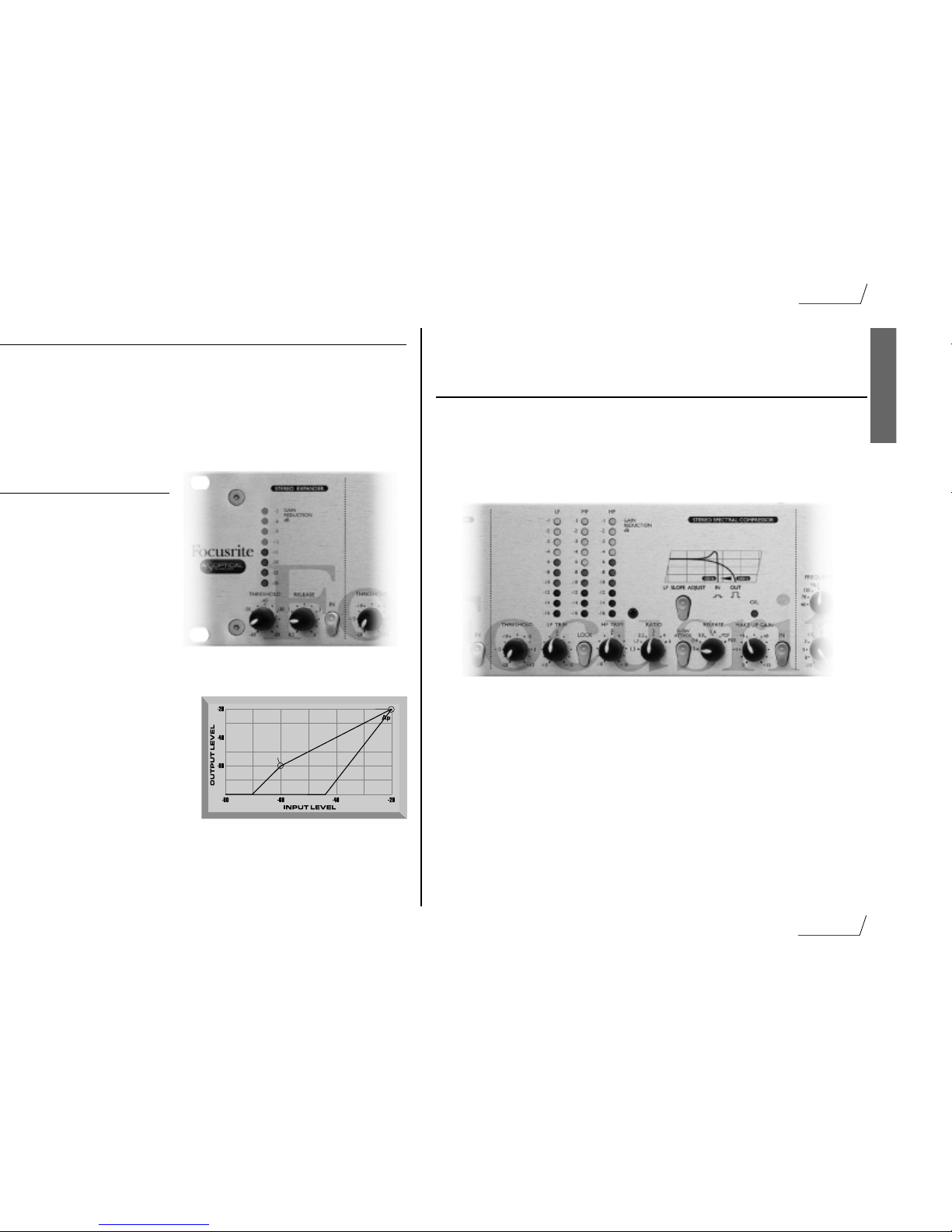
IN - switches the Expander in and out of the signal path to allow easy A/B comparison of the
processed and unprocessed signals. The switch illuminates when pressed to show that the
Expander is active.
STEREO SPECTRAL COMPRESSOR
The spectral multi-band compressor is an optocoupler design, optimised for stereo mix
compression of three independent frequency bands. By splitting the compression across three
bands you avoid the unwanted effect of, for instance, a massive kick drum triggering
compression across the whole stereo signal. The compressor on the MixMaster allows a kick
drum to only affect the LF band, a vocal to compress only mid frequencies, and a hi hat to
compress only the HF band.
THRESHOLD - globally determines the overall level at which compression begins. The
lower the Threshold, the more the signal is compressed. Setting a higher Threshold allows
quieter passages in the music or speech to remain unaffected, and only passages that exceed the
Threshold will be compressed.
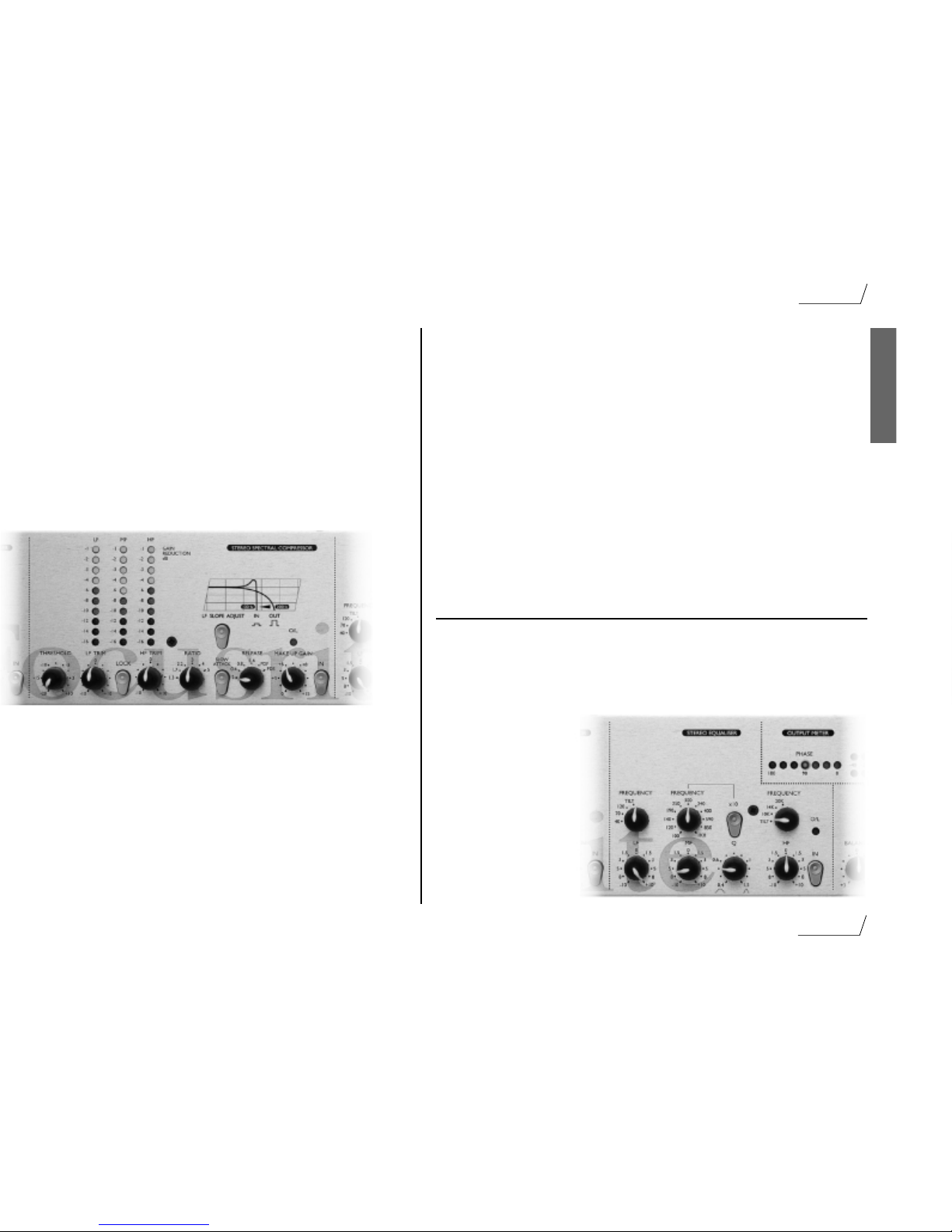
LF/HF TRIM - allow up to 20dB relative variation in threshold between bands, allowing
some very creative use of the compressor. However, note that the audible effect of the Trim
controls is also dependent on the settings of Ratio and Threshold. At high Ratio and lower
Threshold more relative variation will be achieved. If a more gentle effect is required the
LF/HF Trims should be bypassed by pushing the Lock switch (see below).
LOCK - sums the thresholds of the three bands when pressed to give even compression across
the full frequency range. This might be used to preserve the tonal character of signals which
have an unusual spectral balance making it difficult to get equal compression in each band.
Alternatively it may be used when you deliberately want a very “compressed” sound, or when
you want the more gentle feel of a classic compressor.
-60 Threshold
-20 Threshold
Page 8
8
Using the MixMaster
E
N
G
L
I
S
H
RELEASE - determines how quickly compression dies away once the level of the source
signal has fallen below the threshold. When in the anticlockwise position, the compression
releases very quickly, which may be appropriate on rapidly varying signals to avoid compressing
the beats that follow, but can result in distortion on more sustained material. Slower release
times give a smoother effect, but at the same time may result in transients causing audible
“pumping”. Two additional switch positions provide Programme Dependent Fast (PDF) or
Programme Dependent Slow (PDS) release times which respond automatically to the dynamics
of the signal, giving a fast release for transients and a slower release for the average level. The
PDF setting might typically be used for pop tracks, or PDS for classical material.
MAKE UP GAIN - adds gain back in to compensate for the gain reduction due to
compression. The amount of gain reduction displayed on the bargraph meters will give a useful
guide to the amount of Make Up Gain required.
O/L LED - gives warning of excessive signal levels which may result from the addition of
too much Make Up Gain. The O/L LED thus reads from a point in the circuit immediately
after the compressor section.
IN - switches the Compressor into the signal path when pressed. The switch illuminates when
pressed to show that the Compressor is active.
STEREO EQUALISER
The stereo 3-band Parametric EQ has stepped frequency shelving high and low bands and a
parametric mid band. The whole EQ circuit is designed to give gentle, musical control
appropriate to the final phase of a mix.
LF / FREQUENCY - the LF control gives 10dB boost or cut at a roll-off frequency of
40, 70 or 120Hz as selected by the FREQUENCY switch. For more gentle control of the bass
content of the mix the TILT
setting selects a 2dB/octave
slope. Selecting ‘TILT’ allows
subtle control of a broad
range of low frequencies,
starting at 1kHz.
MF / FREQUENCY -
the parametric mid band has
10dB boost or cut provided
by the MF control, and
centre FREQUENCY
selectable from 100Hz to
10kHz in two ranges.
Page 9
9
Using the MixMaster
E
N
G
L
I
S
H
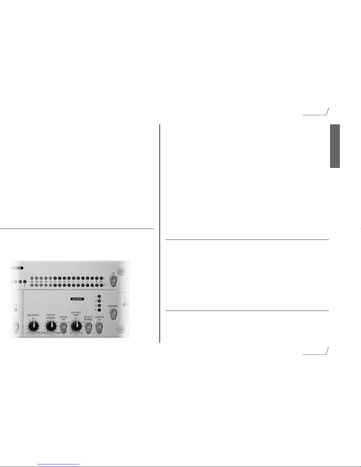
WIDTH - allows the apparent width of the stereo image to be increased to make the sound
seem more spacious, or to be reduced to give a tighter image. WIDTH is only active when the
IMAGE IN switch is pressed. Signals may be isolated from this section by being routed into the
MixMaster after the width control circuit, using the Direct Input - see “Direct Input” section
below. The width control works by analysing the difference between the right and left signals
and then amplifying the difference (width enhanced) or reducing this difference (width
reduced).
IMAGE IN - activates the BALANCE and WIDTH controls when pressed. The switch
illuminates to show that the IMAGE controls (Balance and Width) are active.
OUTPUT TRIM - gives ±6dB of trim to optimise the output level to various recorders.
Adjust so that peaks in the signal are reaching ‘0’ on the output meters with only occasional
limiting shown by blinking of the top Limiter Meter LEDs.
EFFECT BYPASS - switches the Expander, Compressor, EQ and Image sections out of
circuit when pressed. This switch does not affect the operation of the Limiter (see below).
LIMITER IN - activates the multiband limiter, which has a fixed threshold matched to the
input of the optional Digital Output. The Limiter is designed to operate just before the
overload threshold on the meters. The switch illuminates to show that the Limiter is active.
MAIN BARGRAPH METERS
I/P switch - when pressed, switches the bargraph meters and the phase meter to read the
input of the unit. With the switch in the ‘out’ position, the meters monitor the output signal,
after the limiter but before the optional Digital Output.
PHASE meter - a 180º meter monitors phase coherence - important to avoid unexpected
nulling if the signal is to be reproduced in mono.
OUTPUT LEVEL METERS - 16 segment LED bargraphs monitor the output signal,
or the input signal if the I/P switch is pressed. The far right LED (O/L) acts as an overload
indicator to warn of excessive levels which might result in severe distortion, particularly when
feeding external digital equipment or the optional Digital Output.
DIRECT INPUT
Two rear panel jacks are provided to allow a separate external signal to be mixed into the final
output, before the Limiter but after the Image section to add, for instance, a vocal or kick drum
in the centre with different processing. A mono source may be plugged into the
RIGHT/MONO jack to be automatically fed to both sides if required.
Page 10
10
Using the MixMaster
E
N
G
L
I
S
H
APPLICATIONS
Recording/Live
console
stereo sound module
line in
bus sends
PRO TOOLS
to record
insert
sends
insert returns
L & R
in
L & R
out
hard disk recorder
At Mixdown
input sources
returns
sends
L & R
out
L & R
in
stereo insert
pre or post master fader
stereo bus
Page 11
11
Using the MixMaster
E
N
G
L
I
S
H
L & R in
L & R out
L & R
out
L & R
in
DAT tape
L & R
out
L & R
in
digital
out
Direct
input L & R
summed
main mix
submix to
direct inputs
Direct I/P
Mixing Two Stereo Sources
summed
main mix
vocal
direct
input
right
(mono)
Mixing with Vocals
This example makes use of the
limiter and A/D converter without
passing through the preceding
processing sections.
In this example the main
mix is compressed and
EQ’d with a vocal added in
the middle, unaffected by
the processing sections.
The main mix is compressed
and EQ’d and the submix is
added in stereo but without
being effected by the
processing sections.
Page 12

12
Tips on Home Mastering
E
N
G
L
I
S
H
here’s a world of difference between what goes on in a professional mastering suite and
what the average home studio owner can do at home, but as more lower cost
mastering tools become available, it’s quite possible to achieve very impressive results in
2
Once you have decided on a running order for the tracks on the album, you’ll
need to get the levels to match. This doesn’t simply mean making everything the same
level though as this will make any ballads seem very loud compared to more meaty songs. The
vocals often give you the best idea of how well matched songs are, but ultimately your ears are
the best judges.If using disc based storage and editing programs, use the computers ability to
access any part of the album at random to compare the subjective levels of different songs and
pay particular attention to the levels of the songs either side of the one you’re working on. It’s
in the transition of one song to the next that bad level matching shows up most.
3
If the tracks were recorded at different times or in different studios, they may
not sound consistent enough to sit together comfortably on the album without further
processing. Often a little careful EQ will improve matters, but you need a good parametric
equaliser if you’re not to make matters worse. Listen to the bass end of each song to see how
that differs and use the EQ to try to even things out. For example, one song might have all the
bass energy bunched up at around 80 or 90Hz while another might have an extended deep bass
that goes right down to 40Hz or below. By rolling off the sub-bass and peaking up the 80Hz
area slightly, you may be able to bring the bass end back into focus.
Similarly, the track with the bunched up bass could be treated by adding a gentle 40Hz boost
combined with a little cut at around 120Hz. Every equalizer behaves differently so there are no
hard and fast figures you’ll need to experiment. At the mid and high end, use gentle boost at
between 6 and 15kHz to add air and presence to a mix while cutting at between 1 and 3kHz to
reduce harshness. Boxiness tends to occur between 150 and 400Hz. If you need to add top to
a track that doesn’t have any, try a harmonic enhancer,high end EQ boost will simply increase
the hiss.
4
To make a track sound louder when it’s already peaking close to full scale, use a
limiter. In most cases, you can increase the overall level by up to 6dB or even more before
your ears notice that the peaks have been processed in any way. It’s always good practice to
normalize the loudest track on an album to peak at around -0.5dB and then balance the others
to that one. Normalising or other level matching changes should always be the last thing you
do as all EQ, dynamics or enhancement involves some degree of level change. Proper redithering at the 16-bit level is also recommended if going direct via a digital output to the
production master tape as it preserves the best possible dynamic range. Analogue outputs will
be redithered by the A-D of the recorder.
5
If a mix sounds too middly or a little lacking in definition, I suggest using an
enhancer though , you have to be very careful not to overuse it, otherwise the mix might
sound too harsh. Keep switching the process in and out so as to preserve your sense of
perspective. The same applies to EQ and dynamics too - make regular checks against the
untreated version to make sure you haven’t actually made things worse.
Page 13

13
Tips on Home Mastering
E
N
G
L
I
S
H
Listen to the finished master all the way through, preferably using headphones as
these have the ability to show up small glitches and noises that loudspeakers may mask.
Try to work from a 44.1kHz master tape if the end product will be a CD
master. If you have to work from a 48kHz tape or one with different tracks recorded
12
When transferring digital material into a computer, ensure that the computer
hardware is set to external digital sync when you are recording and internal
sync when you play back. Also double check your record sample rate matches the source
sample rate clients will often present you with DAT tapes either at the wrong sample rate or
even with different tracks at different sample rates. All too often this is overlooked until the
client realises that one of the songs is playing back around 10% too slow!
13
If you’re using a digital de-noising program, don’t expect it to work
miracles even the best systems produce side effects if you try to push them
too far. The simpler systems are effectively multi-band expanders where the threshold of each
band is set by first analysing a section of noise from between tracks. For this reason it’s best not
to try to clean up your original masters prior to editing, otherwise there may be no noise
samples left to work from. Used carefully, you can get a few dB of noise reduction before the
side effects set in as low level signals open and close the expanders in the various bands, the
background noise is modulated in a way that can only be described as ‘chirping’. The more
noise reduction you try to achieve, the worse the chirping, so it’s best to use as little as you can
get away with.
14
When editing individual tracks, for example, when compiling a version from all the
best sections of several mixes or recordings, try to make butt joins just before or
just after a drum beat so that any discontinuities are masked by the beat. However, if you
have to use a cross fade edit to smooth over a transition, try to avoid including a drum beat in
the cross fade zone or you may hear a phasing or flamming effect where the two beats overlap.
As a rule, cross fades should be as short as you can get away with so as to avoid getting a
double-tracked effect during the fade zone. As little as between 10 and 30ms is enough to
avoid producing a click.
15
On important projects, run off two copies of the final mastered DAT tape
(one as a backup) and mark these as production master and clone. Write the sample
rate on the box along with all other relevant data. If you include test tones, document their
level and include a list of all the track start times and running lengths for the benefit of the CD
manufacturer. As mentioned earlier, if for any reason you have produced a 48kHz sample rate
master, mark this clearly on the production DAT master so that the CD manufacturer can
sample rate convert it for you.
It is always a good idea to avoid recording audio during the first minute or so of a new DAT
tape to avoid the large number of drop outs commonly caused by the leader clip in the tape
spool hub. You can however use this section to record test tones, which will also demonstrate
to the person playing your tape that it isn’t blank! If you put DAT start IDs on each track,
check them carefully to make sure there are no spurious ones and don’t use skip IDs.
Page 14

14
Tips on Home Mastering / Specifications
E
N
G
L
I
S
H
When deciding on the space between tracks on an album, listen to how the first
track ends and how the second one starts. Gaps are rarely shorter than two
When using CD-R to produce a master that will itself be used for
commercial CD production, the disc must be written in disk-at-once mode
Be aware that stand-alone audio CD recorders tend to have an automatic
shut-off function if gaps in the audio exceed a preset number of seconds,
When making a digital transfer from a DAT recorder to a CD recorder that can read
DAT IDs, it’s best to manually edit the DAT IDs first so that they come at
Specifications
Inputs:
Electronically balanced, impedance 20KΩ, nominal level +4dBu/-10dBV.
Outputs:
Electronically balanced, impedance 50Ω, nominal level +4dBu.
Unbalanced, ground compensated, impedance 75Ω, nominal level -10dBV.
Headroom:
22dB
THD @ 0dBr, all sections in, no gain reduction:
<0.006%(80KHz BW) Distortion during gain reduction is determined by
the attack and release times set.
Noise (22KHz):
-100dBr (all sections out)
<-90dBr (all sections in)
Frequency response:
5Hz....200KHz +0/-2dB
Dimensions:
480 mm (W) x 88 mm (H) x 265 (D)
Weight:
5.2kg
Page 15
D
E
U
T
S
C
H
15
Einleitung
Anschlüsse und Schalter auf der Rückseite
Der MixMaster bietet XLR- sowie dreipolige 6,3 mm-Klinkenbuchsen, die für Signale mit Linepegel
ausgelegt sind. Durch Einstecken eines Klinkensteckers in eine der 6,3 mm-Buchsen wird der
entsprechende XLR-Eingang abgeschaltet. Die nominale Empfindlichkeit der XLR-Eingänge beträgt
+4 dBu, um den problemlosen Anschluss an professionelle Studiogeräte mit symmetrischen Ausgängen –
wie Mischpulte oder professionelle Recorder – zu ermöglichen. Die Klinkenbuchsen haben eine
Empfindlichkeit von -10 dBV und können zum Anschluss von semiprofessionellen oder ConsumerGeräten wie CD-Player, DAT-Recorder oder für Tonerzeuger verwendet werden.
Zusätzlich steht ein Stereo-Direkteingang in Form von zwei 6,3 mm-Klinkenbuchsen mit einer
Empfindlichkeit von +4 dBu zur Verfügung. Eine Mono-Quelle wie beispielsweise ein
Mikrofonvorverstärker kann auf beide Kanäle gelegt werden, indem Sie ihn an den rechten Eingang –
»Direct Input Right (Mono)«– anschließen.
Die analogen Ausgänge des MixMaster sind als XLR- (+4 dBu) und Klinkenbuchsen ausgeführt
(-10dBV). Verwenden Sie die XLR-Buchsen zum Anschluss an professionelle Studiogeräte oder die
Klinkenbuchsen zum Anschluss an semiprofessionelle Geräte.
Ergänzend zu den analogen Ausgängen kann ein hochwertiger digitaler Ausgang mit 128fachem
Oversampling (64faches Oversampling bei hohen Sampleraten) installiert werden. Mit den entsprechenden
Schaltern auf der Rückseite können Sie dann zwischen den Auflösungen 16 und 24 Bit und den
Samplingfrequenzen 44,1 kHz, 48 kHz, 88,2 kHz oder 96 kHz umschalten. Über den integrierten BNCEingang können Sie den Digitalausgang auch zu einem externen Wordclock-Signal synchronisieren.
Das Format des digitalen Ausgangssignals kann zwischen den Standards AES/EBU (XLR-Buchse) und
SPDIF (Cinch-Buchse) umgeschaltet werden.
Page 16

16
Bedienelemente
D
E
U
T
S
C
H
IN – mit diesem Schalter können Sie den Expander aus dem Signalweg schalten, um einen A/B-
Vergleich zwischen bearbeitetem und unbearbeitetem Signal durchzuführen. Wenn der Expander aktiv ist,
leuchtet die LED des Schalters.
Stereo Spectral Compressor
Der auf einer Optokoppler-Schaltung beruhende Multiband-Kompressor des MixMaster wurde für die
Stereo-Kompression von drei unabhängigen Frequenzbändern optimiert. Da die Kompression in drei
getrennten Bereichen stattfindet, wird vermieden, dass zum Beispiel eine sehr laute Bassdrum das gesamte
Signal »herunterzieht«. Beim MixMaster löst eine Bassdrum nur eine Kompression im Bassbereich aus, die
Stimme beeinflusst nur die Mitten und die HiHat nur den Höhenbereich.
THRESHOLD – Dieser Parameter definiert den Basis-Schwellwert, ab dem die Kompression
einsetzt. Je niedriger der Schwellwert ist, um so stärker wird das Signal komprimiert. Wenn Sie den
Threshold-Wert höher setzen, werden leise Passagen einer Aufnahme nicht beeinflusst.
LF TRIM/HF TRIM – mit diesen Reglern kann der Schwellwert für den Bass- und
Höhenbereich in einem Bereich von 20 dB gegenüber dem Basis-Schwellwert verschoben werden,
wodurch sich weit reichende Möglichkeiten zur Klanggestaltung ergeben. Beachten Sie jedoch, dass die
erzielte Wirkung auch von den Einstellungen der RATIO- und THRESHOLD-Parameter abhängt: Bei
hohen RATIO- und niedrigen THRESHOLD-Einstellungen fallen auch die Abweichungen für den
unteren und oberen Frequenzbereich stärker aus. Wenn Sie eine zurückhaltendere Kompression
wünschen, sollten Sie mit dem nachfolgend beschriebenen LOCK-Schalter die beiden TRIM-Regler
deaktivieren.
LOCK – Wenn dieser Schalter gedrückt ist, werden die Schwellwerte aller drei Frequenzbänder
zusammengefasst, um eine gleichmäßige Kompression über den gesamten Frequenzbereich zu erzielen.
Auf diese Weise kann der Klangcharakter eines ungewöhnlich zusammengesetzten Signals erhalten
werden, das ansonsten durch eine mehrbandige Kompression nur schwer erfasst werden kann. Sie können
den LOCK-Schalter aber auch verwenden, wenn Sie einen ausgesprochen »komprimierten« Sound
wünschen oder den Klang eines klassischen Kompressors nachbilden wollen.
-60 Threshold
-20 Threshold
Page 17

17
Bedienelemente
D
E
U
T
S
C
H
RELEASE – Dieser Regler definiert, wie schnell die Kompression wieder aufgehoben wird, sobald
das Signal unter den eingestellten Schwellwert fällt. Bei einer niedrigen Einstellung (Regler gegen den
Uhrzeigersinn gedreht) wird die Kompression sehr schnell aufgehoben, was bei einer sehr dynamischen
Aufnahme das unerwünschte Komprimieren nachfolgender Einsätze/Zählzeiten verhindert, bei
kontinuierlichen Signalen aber eher zu Verzerrungen führen kann. Längere Release-Werte erzeugen einen
weicheren Klang, können andererseits bei perkussivem Material zu hörbarem »Pumpen« führen. Bei den
beiden folgenden Reglerstellungen PDF (= Programme Dependent Fast) und PDS (Programme
Dependent Slow) folgt die Releasedauer der Dynamik, sodass bei Einschwingvorgängen schneller und bei
gleichmäßigem Signalverlauf langsamer freigegeben wird. Die PDF-Einstellung eignet sich vor allem für
Pop-Aufnahmen, PDS eher für Klassik.
MAKE UP GAIN – hebt das Signal etwas an, um den durch Kompression entstandenen
Pegelverlust zu kompensieren. Orientieren Sie sich bei der Einstellung an der durch die GAIN
REDUCTION-LED-Ketten angezeigten Kompression.
O/L LED – Wenn es zu Übersteuerungen durch eine zu hohe MAKE UP GAIN-Einstellung kommt,
leuchtet diese LED auf. Sie überwacht einen Punkt im Signalweg direkt nach dem Kompressor-Bereich.
IN – mit diesem Schalter können Sie den Kompressor aus dem Signalweg schalten, um einen A/B-
Vergleich zwischen bearbeitetem und unbearbeitetem Signal durchzuführen. Wenn der Kompressor aktiv
ist, leuchtet die LED des Schalters.
Stereo-Equaliser
Der parametrische 3 Band-Stereo-EQ des MixMaster hat je einen abgestuften Regelbereich mit ShelvingCharakteristik für Tiefen und Höhen sowie einen parametrischen Mittenbereich. Der gesamte EQSchaltkreis wurde für eine möglichst »schonende«, musikalische Bearbeitung in der Endphase einer
Mischung entwickelt.
LF / FREQUENCY – Je nach Stellung des FREQUENCY-Schalters dämpft oder verstärkt der
LF-Regler das Signal bei 40, 70 oder 120 Hz um 10 dB. Um den Bassanteil des Signals etwas subtiler zu
steuern, wählen Sie die TILT-Einstellung für eine Flankensteilheit von 2 dB/Oktave. Bei dieser
Einstellung steuert der LF-Regler einen größeren Frequenzbereich unterhalb von 1 kHz.
MF / FREQUENCY –
der Mittenbereich kann mit dem
MF-Regler um 10 db angehoben
oder abgesenkt werden. Die
Mittenfrequenz kann mit dem
FREQUENCY-Regler in einem
von zwei Regelbereichen
zwischen 100 Hz und 10 kHz
eingestellt werden (s. folgender
Parameter).
Page 18

18
Bedienelemente
D
E
U
T
S
C
H
WIDTH – verstärkt oder schwächt den Stereo-Eindruck, um den Klang räumlicher oder konzentrierter
wirken zu lassen. Dieser Regler ist nur aktiv, wenn der IMAGE IN-Schalter gedrückt ist. Sie können ein
Signal von der Bearbeitung mit diesem Schaltkreis ausnehmen, indem Sie es mithilfe der Direkteingänge
erst danach zumischen – siehe hierzu den Abschnitt »Direkteingang«. Die Width-Funktion analysiert die
Unterschiede zwischen linkem und rechtem Signal und verstärkt (Regelbereich »Wide«) diesen
Signalanteil beziehungsweise senkt ihn ab (Regelbereich »Small«).
IMAGE IN – erst wenn dieser Schalter gedrückt ist (angezeigt durch Leuchten der integrierten LED),
werden die Regler BALANCE- und WIDTH aktiviert.
OUTPUT TRIM – mit diesem Regler können Sie den Ausgangspegel um ±6 dB justieren, um ihn
optimal an das im Signalweg folgende Gerät anzupassen. Stellen Sie diesen Regler so ein, dass der
Signalpegel bis 0 reicht und der Limiter höchstens gelegentlich aktiv wird.
EFFECT BYPASS – wenn dieser Schalter gedrückt ist, werden Expander, Kompressor, EQ und
Stereo Image-Bereich aus dem Signalweg geschaltet. Dieser Schalter hat keine Auswirkung auf den
Limiter (siehe hierzu den folgenden Absatz).
LIMITER IN – aktiviert den Multiband-Limiter, dessen festgelegter Schwellwert auf den als Zubehör
erhältlichen Digitalausgang abgestimmt ist. Der Limiter setzt unmittelbar unter dem Pegel ein, der mit den
Overload-LEDs der Pegelanzeige angezeigt wird. Wenn der Schalter gedrückt ist, leuchtet die integrierte
LED.
Haupt-Pegelanzeige
I/P-Schalter – wenn dieser Schalter gedrückt ist, zeigen die Pegelanzeigen das Signal am Eingang
des MixMaster. Wenn der Schalter nicht gedrückt ist, zeigen sie das Ausgangssignal nach dem Limiter,
aber vor dem als Option erhältlichen Digitalausgang.
PHASE - Anzeige – diese 180º-Phasenanzeige prüft die Phasenkohärenz. Auf diese Weise erkennen
Sie Abweichungen, die zu Auslöschungen bei der Monowiedergabe führen könnten.
OUTPUT METER - Anzeige – die aus 2 x 16 LEDs bestehende Anzeige zeigt den Pegel des
Ausgangssignals oder – bei gedrücktem I/P-Schalter – den Eingangspegel. Die letzte, mit O/L
bezeichnete LED dient als Überlastungsanzeige. Ein hierdurch angezeigte Übersteuerung sollte
insbesondere bei der Ansteuerung digitaler Aufzeichnungssysteme oder bei Verwendung des optionalen
Digitalausgangs vermieden werden, damit keine hörbaren Verzerrungen auftreten.
Direkteingang
Ergänzend steht ein Stereo-Direkteingang in Form von zwei 6,3 mm-Klinkenbuchsen auf der Rückseite
des Gerätes zur Verfügung. So kann ein fertiger Mix durch ein weiteres Signal mit einer separaten – oder
ganz ohne – Klangbearbeitung ergänzt werden; beispielsweise Gesang oder eine Bassdrum. Eine MonoQuelle kann auf beide Kanäle gelegt werden, indem Sie diese an den rechten Eingang – »Direct Input
Right (Mono)« – anschließen.
Page 19

19
Bedienelemente
D
E
U
T
S
C
H
Einsatzbereiche/Anwendungsbeispiele
Aufnahmen/Livebetrieb
console
stereo sound module
line in
bus sends
PRO TOOLS
to record
insert
sends
insert returns
L & R
in
L & R
out
hard disk recorder
Abmischung
input sources
returns
sends
L & R
out
L & R
in
stereo insert
pre or post master fader
stereo bus
Page 20

20
Einsatzbereiche/Anwendungsbeispiele
D
E
U
T
S
C
H
L & R in
L & R out
L & R
out
L & R
in
DAT tape
L & R
out
L & R
in
digital
out
Direct
input L & R
summed
main mix
submix to
direct inputs
summed
main mix
vocal
direct
input
right
(mono)
Direkteingang
In diesem Beispiel werden Limiter und
A/D-Wandler verwendet, ohne dass das
Signal die vorgeschalteten
Signalverarbeitungsbereiche durchläuft.
Mischen plus
Gesang
In diesem Beispiel wird der
Haupt-Mix komprimiert und
mit dem EQ bearbeitet. Das
Signal des am rechten
Direkteingang angeschlossenen
Mikrofons erscheint ohne
weitere Signalbearbeitung in
der Mitte des
Stereoklangbildes.
Mischen von zwei
Stereosignalen
Der Haupt-Mix wird
komprimiert und mit dem EQ
bearbeitet. Der an den
Direkteingängen anliegende
Submix wird in stereo
dazugemischt, ohne die
Signalbearbeitung zu durchlaufen.
Page 21

21
Technische Daten
D
E
U
T
S
C
H
Page 22

F
R
A
N
Ç
A
I
S
22
Introduction
CONNEXIONS ET RÉGLAGES EN FACE ARRIéRE
Le MixMaster est équipé d’entrées à niveau ligne sur connecteurs XLR et Jacks stéréo 6,35 mm :
l’insertion d’un jack désactive automatiquement le connecteur XLR correspondant. La sensibilité
nominale de l’entrée XLR est de +4 dBu ; cette caractéristique le rend compatible avec les appareils
au standard professionnel équipés de sorties symétriques (consoles ou enregistreurs professionnels). La
sensibilité nominale du jack d’entrée est de –10 dBV ; cette caractéristique le rend compatible avec
les appareils semi-professionnels ou grand public (lecteurs de CD, platines DAT et modules de sons).
Le MixMaster offre une entrée stéréo supplémmentaire d’une sensibilité de +4 dBu sur deux jacks
6,35 mm. Une source mono, comme le signal de sortie d’un préamplificateur micro, peut être
dirigée vers les deux canaux en procédant à une connexion sur le jack de droite seul (Mono).
Les sorties analogiques symétriques s’effectuent sur connecteurs XLR (+4 dBu) ou jack
(-10 dBV), respectivement compatibles avec les systèmes professionnels et semi-professionnels.
En plus de la sortie analogique, une sortie stéréo numérique haut de gamme à suréchantillonnage
128 fois (suréchantillonnage 64 fois sur les fréquences d’échantillonnage élevées) peut être installée
en option sur l’appareil. Les sélecteurs en face arrière permettent de sélectionner entre les
résolutions 16 ou 24 Bits avec les fréquences d’échantillonnage à 44,1, 48, 88,2 ou 96 kHz. Cette
sortie peut si nécessaire être synchronisée avec une horloge Wordclock externe via le connecteur
BNC.
Choisissez le format de sortie numérique : AES/EBU (XLR) ou SPDIF (phono).
Page 23

23
Fonctions et commandes
F
R
A
N
Ç
A
I
S
6 secondes. Le temps de rétablissement cours à partir du moment où le signal est passé sous le niveau
du seuil. Appliquez un temps de rétablissement rapide sur les signaux comprenant de nombreuses
transitoires (réglage vers la gauche) ; choisissez un temps de rétablissement plus lent (réglage vers la
droite) pour un résultat plus naturel sur les signaux moins dynamiques. Pour un traitement aussi
discret que possible, fixez un temps de rétablissement légèrement plus lent que le déclin naturel du
signal.
IN – Activation et désactivation de l’expanseur afin de permettre la comparaison entre les signaux
avec et sans traitement. Cette touche est allumée lorsque l’expanseur est actif.
COMPRESSEUR MULTIBANDE STÉRÉO
Le compresseur spectral multibande est de type à optocoupleur ; optimisé pour la compression de
programme stéréo, il opère sur trois bandes de fréquences indépendantes. Le système de compression
trois bandes permet d’éviter que la compression très lourde appliquée sur la grosse caisse n’ait
d’incidence sur l’ensemble du signal stéréo. Le compresseur du MixMaster permet à la compression
appliquée sur la grosse caisse de n’affecter que les graves, à la compression appliquée sur le chant de
n’affecter que les médiums et à la compression appliquée sur les cymbales de n’affecter que les aigus.
THRESHOLD (SEUIL) – Détermine de façon globale le niveau général à partir duquel la
compression est appliquée. Plus le seuil est bas, plus la quantité de signal compressé est importante.
Choisissez un seuil relativement élevé pour que les parties les plus sensibles d’un programme ne
soient pas affectées et que seuls les passages dépassant le seuil soient traités.
LF/HF TRIM (ÉQUILIBRE GRAVES/AIGUS) – Cette fonction permet
d’appliquer une variation relative de 20 dB au seuil des bandes graves et aiguës. Notez cependant que
l’influence de ces commandes sur le signal dépend également des réglages du Ratio et du seuil. Un
réglage élevé du Ratio et un seuil bas accentuent la variation relative.
-60 Threshold
-20 Threshold
Page 24

24
Fonctions et commandes
F
R
A
N
Ç
A
I
S
RELEASE (RÉTABLISSEMENT) – Détermine la vitesse à laquelle la compression
disparaît une fois que le signal est repassé sous le niveau du seuil. Avec un réglage au minimum, la
compression est supprimée très rapidement, ce qui est l’effet recherché sur les passages possédant une
dynamique importante afin d’appliquer une compression très ciblée ; un tel réglage peut s’avérer
maladroit sur des morceaux moins rapides et générer de la distorsion. Les temps de rétablissement
plus lents offrent un effet plus doux mais peuvent en revanche provoquer des effets de ‘pompage’ sur
les transitoires. Deux positions supplémentaires permettent à l’appareil de calculer automatiquement
des temps de rétablissement dits ‘Programme Dependent Fast’ (PDF) et ‘Programme Dependent
Slow’ (PDS) en fonction de la dynamique du morceau ; grâce à ces modes, les temps de
rétablissement sont courts sur les transitoires et lents sur les signaux moyens. Sélectionnez de
préférence le réglage PDF pour la musique Pop et le réglage PDS pour la musique classique.
MAKE UP GAIN (GAIN DE SORTIE) – Applique un gain au signal de sortie
permettant de compenser la réduction de gain appliquée par la compression. L’atténuation affichée
par le bargraph permet d’évaluer le gain de sortie nécessaire.
LED O/L – Indique la présence de signaux trop élevés à cause d’un gain de sortie trop important.
La LED O/L prélève le signal immédiatement après la section de compression.
TOUCHE IN – Cette touche insère le compresseur sur le trajet du signal. Cette touche est
allumée lorsque le compresseur est actif.
CORRECTEUR STÉRÉO
Le correcteur paramétrique stéréo 3 bandes utilise une section de type Baxendall fixe sur les graves et
les aigus et une section paramétrique sur les médiums. L’ensemble du circuit de correction est conçu
pour offrir un contrôle précis et musical sur la phase finale du mixage.
LF/FREQUENCY – La commande LF offre un gain ou une atténuation de 10 dB à 40, 70 ou
120 Hz, tel que sélectionné à l’aide du réglage ‘FREQUENCY’. La position ‘TILT’ sélectionne une
pente très douce à 2 dB/octave.
MF/FREQUENCY
– Le correcteur paramétrique
médium applique un gain ou
une atténuation de 10 dB à
une fréquence réglable sur
une plage comprise entre
100 Hz et 10 kHz selon deux
échelles.
Page 25

25
Fonctions et commandes
F
R
A
N
Ç
A
I
S
différence. Les signaux entrant dans le MixMaster par l’entrée directe évitent cette section en (voir la
section “Entrée directe” ci-après).
TOUCHE IMAGE IN – Appuyez sur cette touche pour activer les circuits ‘BALANCE’ et
‘WIDTH’. Les fonctions ‘IMAGE’ (‘Balance’ et ‘Width’) sont actives lorsque la touche est allumée.
OUTPUT TRIM (GAIN DE SORTIE) – Ce réglage de gain de ±6 dB permet
d’optimiser le niveau de sortie des signaux affectés à des enregistreurs. Ce paramètre doit être réglé
de sorte que les crêtes du signal atteignent le niveau ‘0’ de l’afficheur de niveau de sortie avec
quelques passages entraînant le clignotement des leds les plus hautes de l’afficheur dédié au limiteur.
TOUCHE EFFECT BYPASS – Cette touche déconnecte les circuits de l’expanseur, du
compresseur, du correcteur et du réglage de l’image stéréo. Cette touche n’affecte pas l’action du
limiteur (voir ci-dessous).
TOUCHE LIMITER IN – Cette touche active le limiteur multibande ; celui-ci possède un
seuil fixe, adapté à l’entrée de la sortie numérique optionnelle. Le limiteur est paramétré pour entrer
en action juste avant que les seuils de surcharge des afficheurs ne soient atteints. La touche est
allumée lorsque le limiteur est actif.
AFFICHEURS DE NIVEAUX
TOUCHE I/P – Lorsque cette touche est enfoncée, les afficheurs bargraphs et les afficheurs de
phase visualisent le signal d’entrée. Lorsque cette touche est relevée, ces afficheurs reçoivent les
niveaux de sortie, en aval du limiteur mais en amont de la sortie numérique optionnelle.
Afficheur de PHASE – Cet afficheur contrôle la cohérence de la phase entrte les signaux
gauche et droit , ce qui est essentiel pour éviter les annulations de phase lorsque le signal est
reproduit en mono.
AFFICHEURS DES NIVEAUX DE SORTIE – Ces bargraphs à leds 16 segments
permettent de visualiser les niveaux de sortie ou d’entrée (lorsque la touche ‘I/P’ est enfoncée). La
led de droite (O/L) sert d’indicateur de surcharge et avertit l’utilisateur de la présence de signaux de
niveau excessif pouvant entraîner d’importantes distorsions, en particulier si le signal est dirigé vers
un appareil numérique externe ou vers la sortie numérique optionnelle.
ENTREE DIRECTE
Deux connecteurs sur la face arrière permettent de mélanger sur la sortie finale un signal externe ; ce
mixage s’opère avant l’étage limiteur mais après la section de réglage de l’image stéréo. Ce système
permet par exemple d’ajouter un chant ou une grosse caisse au centre avec un traitement différent.
Une source mono peut ainsi être affectée au connecteur gauche/droite et être dirigée si nécessaire
vers les deux côtés.
Page 26

26
Fonctions et commandes / Applications
F
R
A
N
Ç
A
I
S
APPLICATIONS
Enregistrement/Live
console
stereo sound module
line in
bus sends
PRO TOOLS
to record
insert
sends
insert returns
L & R
in
L & R
out
hard disk recorder
Mixage final
input sources
returns
sends
L & R
out
L & R
in
stereo insert
pre or post master fader
stereo bus
Page 27

27
Using the MixMaster
F
R
A
N
Ç
A
I
S
L & R in
L & R out
L & R
out
L & R
in
DAT tape
L & R
out
L & R
in
digital
out
Direct
input L & R
summed
main mix
submix to
direct inputs
summed
main mix
vocal
direct
input
right
(mono)
Utilisation directe sans
traitement
Cet exemple utilise un limiteur et un
convertisseur A/N sans que le signal ne
passe par les sections de traitement.
Mixage avec des
voix
Dans cet exemple, le signal
de mixage général est traité
par le compresseur et le
correcteur, une voix est
ajoutée au centre, mais celleci n’est pas affectée par les
sections de traitement.
Mixage de deux
sources stéréo
Le signal de mixage général est
traité par le compresseur et le
correcteur, le pré-mixage est
effectué en stéréo, mais n’est pas
affecté par les sections de
traitement.
Page 28

28
Quelques conseils pour le Home Mastering
F
R
A
N
Ç
A
I
S
ueriez au final d’obtenir un résultat bien pire que l’original.
se fait à l’oreille. Si vous utilisez des sauvegardes sur disque dur et des logiciels d’édition, profitez de
la fonction d’accès direct à toutes les parties de l’album pour comparer les niveaux relatifs des
différents morceaux ; en particulier ceux placés avant et après le morceau sur lequel vous travaillez.
C’est sur la transition entre un morceau et le morceau suivant que les décalages de niveaux se font le
plus sentir.
3
Des pistes enregistrées à des moments différents ou dans des studios différents peuvent présenter
des qualités sonores trop distinctes pour pouvoir être placées sans traitement l’une à la suite de
l’autre sur un album. Une légère égalisation, suffit souvent à arranger les choses ; encore faut-il que
vous disposiez d’un correcteur paramétrique de qualité pour ne pas aggraver les choses. Écoutez en
particulier la chute des basses en fin de morceau et harmonisez l’ensemble avec le correcteur.
Exemple : considérons un morceau dont toutes les basses sont concentrées entre 80 et 90 Hz et un
autre morceau comportant des infra-basses descendant à 40 Hz, voire à des fréquences encore plus
basses. En coupant les infra-basses et en accentuant légèrement la bande de fréquences autour des
80 Hz, vous devriez pouvoir ménager une transition plus harmonieuse sur les basses.
En outre, la piste contenant les basses les plus hautes peut être traitée en appliquant un gain autour de
40 Hz et en atténuant le signal au-delà de 120 Hz. Chaque correcteur fonctionne d’une façon
particulière, il n’est donc pas question ici de vous proposer des valeurs de réglage très précises ; vous
devrez procéder à des essais vous-même. Concernant les médiums et les aigus, appliquez un léger
gain entre 6 et 15 kHz afin d’ajouter de l’espace et de la présence à votre mixage et coupez le signal
entre 1 et 3 kHz pour éliminer les sons les plus agressifs. L’impression de confusion sonore apparaît
généralement entre 150 et 400 Hz. Si vous cherchez à ajouter des aigus sur une piste où ils font
défaut, utilisez un Enhancer. Le gain appliqué sur les hautes fréquences par le correcteur vous
permettra de faire ressortir très simplement les aigus.
4
Si vous souhaitez augmenter le niveau d’une piste et si les crêtes du signal approchent du niveau
maximal avant écrêtage, utilisez un limiteur. Dans la plupart des cas, il est possible d’appliquer un
gain maximal de 6 dB sans que le traitement ne soit perceptible. Il est recommandé de toujours
normaliser la piste la plus forte d’un album pour obtenir des crêtes à environ –0,5 dB, puis de régler
les autres pistes par rapport à celle-ci. La normalisation ainsi que tous les réglages d’homogénéisation
des niveaux, doivent intervenir lors de la phase finale du processus de Mastering ; en effet la
correction, le traitement de la dynamique et celui de l’Enhancer introduisent des variations de
niveaux. Un re-dithering à 16 bits est également recommandé pour préserver la plage dynamique
lorsque le signal est transféré directement de la sortie numérique à l’enregistreur Master. Le signal des
sorties analogiques passe forcément par une phase de re-dithering lors de la conversion A/N de
l’enregistreur.
5
Si le son d’un mixage semble manquer légèrement de définition, je vous suggère d’avoir recours
à un Enhancer, en veillant à ne pas en abuser, vous risqueriez de vous retrouver avec un mixage
au son trop agressif dans les aigus. Activez et désactivez successivement le traitement afin de
percevoir les nuances apportées par le traitement. De même pour le correcteur et le traitement de la
dynamique : comparez toujours avec la version non traitée pour être sûr que vous ne détériorez pas
le morceau.
Page 29

29
Quelques conseils pour le Home Mastering
F
R
A
N
Ç
A
I
S
Écoutez attentivement le Master final dans son intégralité, de préférence au casque ; ces
derniers vous offrent en effet la définition suffisante pour vous permettre de distinguer les
Essayez de travailler à 44,1 kHz sur votre enregistreur multipiste si le produit final doit être
gravé sur un CD. Si vous devez travailler avec un multipiste à 48 kHz ou avec des pistes
12
Lors du transfert des données numériques depuis/vers votre ordinateur : Assurez-vous que ce
dernier est configuré pour une synchronisation sur le signal numérique externe en
enregistrement et qu’il est synchronisé sur son horloge interne en lecture. Vérifiez également que
votre fréquence d’échantillonnage en enregistrement corresponde avec celle de la source ; il arrive
souvent que les clients nous présentent des bandes DAT avec de mauvaises fréquences
d’échantillonnage ou des fréquences d’échantillonnage différentes sur chacune des pistes. D’une
manière générale, ce point passe inaperçu, jusqu’à ce que le client réalise que l’un des morceaux est
lu 10 % trop lentement.
13
Si vous utilisez un programme numérique de suppression de bruit, ne vous attendez pas à des
miracles, même les systèmes les plus performants ont leurs limites. Les systèmes les plus
simples sont les expanseurs multibandes, sur lesquels les seuils de chacune des bandes sont réglés après
analyse préalable d’une section de chacune des bandes. Pour cette raison, il est préférable de ne pas
‘nettoyer’ vos Masters originaux avant l’édition, si vous voulez être sûr qu’il reste des échantillons
sonores à partir desquels vous pourrez travailler. Si vous l’utilisez avec discernement, ce programme
peut appliquer une réduction de quelques décibels avant que des effets parasites n’apparaissent à
mesure que les signaux de faibles niveaux ouvrent et ferment les expanseurs sur les différentes bandes
de fréquences. Le bruit de fond est alors modulé et donne un son rappelant un ‘gazouillement’. Plus
vous cherchez à obtenir une réduction importante du signal, plus cet effet est prononcé, il est par
conséquent recommandé d’appliquer un traitement aussi léger que possible.
14
Lorsque vous éditez des pistes individuelles, lorsque vous compilez les meilleurs extraits de
plusieurs mixages ou enregistrements par exemple, essayez dans la mesure du possible de faire
vos raccords juste après un coup de batterie de façon à masquer les discontinuités dans le jeu. Si vous
préférez utiliser un fondu entre les deux sections pour ménager une transition plus douce, évitez
d’inclure un coup de batterie dans la zone du fondu, vous risqueriez d’obtenir un effet de Phasing ou
de roulement en cas de répétition de deux coups de batterie. En règle générale, créez des fondus les
plus courts possibles afin d’éviter les effets de répétition générés par le recouvrement des pistes. Des
fondus entre 10 et 30 ms sont suffisants pour éviter tout bruit de ‘clic’.
15
Sur les projets importants, gardez deux copies du Master final sur bande DAT (l’une des deux
servant de sauvegarde). Indiquez sur les boîtiers la fréquence d’échantillonnage et toutes les
informations que vous jugerez pertinent de mentionner. Si vous incluez des signaux test sur ces
bandes, notez leur niveau et ajoutez la liste des références temporelles de début de morceaux et la
longueur de ces derniers pour faciliter la tâche de l’entreprise de production du CD. Comme nous
l’avons rappelé précédemment, si pour une raison ou pour une autre, vous avez été amené à créer un
Master avec une fréquence d’échantillonnage à 48 kHz, indiquez-le clairement sur votre Master
DAT afin que l’entreprise de production du CD puisse procéder à la conversion.
Il est toujours préférable de n’enregistrer aucun signal pendant la première minute sur la bande DAT
pour éviter d’enregistrer sur les parties de bandes dégradées (par le frottement des têtes sur la bande),
ce qui conduit à des dégradations du signal sur ces zones. Vous pouvez en revanche exploiter cette
section pour enregistrer des signaux test, qui signaleront en outre à toute personne lisant cette bande
Page 30

30
Quelques conseils pour le Home Mastering / Caractéristiques
F
R
A
N
Ç
A
I
S
Lorsque vous cherchez à déterminer l’espace à laisser entre les pistes d’un album, écoutez bien
comment fini la première et comment commence la seconde. Les intervalles sont rarement
Si vous utilisez un CD-R pour créer un Master qui sera à son tour utilisé pour la production
commerciale d’autres CD, gravez ce dernier d’un bloc (Disk at Once) et non pas une piste à
Sachez que certains graveurs de CD audio externes possèdent une fonction de mise en veille
automatique après 6 ou 20 secondes de silence. Cette fonction peut poser problème si vous
Lorsque vous procédez à un transfert de données numériques entre un DAT et un graveur de
CD capable de lire les identifiants DAT, il est préférable d’éditer auparavant les identifiants
Caractéristiques
Entrées:
Entrée à symétrie électronique, impédance 20 kΩ, niveau nominal +4 dBu/-10 dBV.
Sorties :
Symétrie électronique, impédance 50 Ω, niveau nominal +4 dBu.
Asymétrique, à compensation de masse, impédance 75 Ω, niveau nominal –10 dBV.
Réserve dynamique :
22 dB
Distorsion harmonique totale
à 0 dBr, toutes sections activées, sans réduction de gain :
<0,006 %(largeur de bande 80 KHz) La distorsion pendant la réduction de gain est
déterminée par le réglage des temps d’attaque et de rétablissement
Bruit (22 kHz) :
-100 dBr (toutes sections désactivées)
<-90 dBr (toutes sections activées)
Réponse en fréquence :
5 Hz....200 kHz +0/-2 dB
Dimensions:
480 mm (l) x 88 mm (h) x 265 (p)
Poids:
5,2 kg
Page 31

I
T
A
L
I
A
N
O
31
Introduzione
Pannello Posteriore
Mixmaster è provvisto di ingressi a livello linea con connessioni XLR e Jack ?” stereo,
inserendo un jack si escluderà il relativo XLR. La sensibilità nominale dell’ingresso XLR è
+ 4 dBu, per la connessine di apparecchiature professionali, mixer o registratori, con uscite
bilanciate. L’ingresso Jack ha una sensibilità nominale di –10dBV per interfacciarsi ad
apparecchiature semi professionali o consumer, lettori CD, registratori DAT o schede audio.
Un doppio ingresso diretto a + 4dBu con connessioni Jack ?”, consente di sommare sorgenti
esterne all’uscita; per l’utilizzo con sorgenti mono, come un preamplificatore microfonico, è
possibile utilizzare il solo ingresso Right (Mono) per indirizzare il segnale su entrambi i canali.
Sono previsti come standard, uscite bilanciate con connessioni XLR (+ 4dBu) e Jack
(- 10dBV), per incontrare le esigenze professionali e semi professionali.
In uscita può essere aggiunta, come opzione, una scheda di conversione di alta qualità (128X
Oversampling, 64X ad alte frequenze di campionamento). Pulsanti sul pannello posteriore
consentono di scegliere la risoluzione, di 16 o 24 bit e la frequenza di campionamento, fra 44.1,
48, 88.2 o 96 Khz. L’uscita può essere sincronizzata ad un Word Clock esterno attraverso un
connettore BNC.
Il formato dell’uscita digitale è selezionabile, fra AES/EBU (XLR) e S/PDIF (phono).
Page 32

32
Funzioni e Controlli
I
T
A
L
I
A
N
O
IN - inserisce la sezione Expander nel percorso del segnale, permettendo una semplice
comparazione fra il segnale originale e quello processato. Il tasto si illumina quando premuto,
mostrando che l’Expander è attivo.
Stereo Spectral Compressor
Il compressore MultiBanda, con architettura optoelettrica è ottimizzato per la compressione di
programmi stereo su tre bande di frequenza indipendenti. Suddividendo la compressione su tre
bande è possibile evitare gli spiacevoli effetti, ad esempio, di una cassa troppo presente, che
controlla la compressione su tutto il resto del segnale. Con MixMaster la cassa ed il basso
influenzeranno solo la banda delle basse la voce solo la banda delle medie ed il charleston solo
quella delle alte.
THRESHOLD - Il controllo “Threshold” (Soglia) determina il livello dal quale inizia la
compressione. Più la soglia è bassa, maggiore sarà la compressione, viceversa, regolando questo
parametro su valori più alti, i segnali più bassi verranno lasciati inalterati e la compressione avrà
effetto solo su segnali più alti che eccedono il valore di soglia.
LF/HF TRIM - Consente 20 dB di variazione relativa della soglia tra le bande, permettendo
un uso del compressore realmente creativo. Le variazioni sono inoltre legate alla posizione dei
controlli Thereshold e Ratio, con bassi livelli di soglia ed alti rapporti di compressione, l’effetto
di compressione differenziata sarà più udibile, per un effetto meno intrusivo è possibile
eliminare le variazioni relative dei controlli LF/HF Trim schiacciando il tasto Lock.
LOCK – Somma le soglie delle tre bande quando è necessaria una compressione equivalente
su tutto lo spettro di frequenze. Può essere utilizzato per preservare le caratteristiche tonali di
un segnale con un bilanciamento spettrale inusuale che renda difficile la compressione uguale di
tutte le tre bande. In alternativa può utilizzarsi se si desidera un suono deliberatamente
sovracompresso, o viceversa per ottenere il risultato morbido tipico di un compressore
tradizionale.
-60 Threshold
-20 Threshold
Page 33

33
Funzioni e Controlli
I
T
A
L
I
A
N
O
RELEASE - Questo controllo (Rilascio) determina quanto velocemente venga rimossa la
compressione una volta che il segnale scende di nuovo sotto la soglia impostata. Con il
potenziometro ruotato in senso antiorario il tempo di rilascio è brevissimo, questa regolazione è
utile per suoni con transienti molto rapidi, ma può introdurre maggiore distorsione in presenza
di segnali più continui. Ruotando il controllo in senso orario si ottengono tempi di rilascio più
lenti, con una compressione più morbida che comporta però maggior effetto di “pompaggio”
con segnali impulsivi. Due ulteriori pulsanti inseriscono il rilascio automatico dipendente dalle
caratteristiche del programma che può essere rapido, PDF (Program Dependent Fast) o più
lento, PDS (Program Dependent SloW), rispettivamente utili per programmi Pop o Dance e
per programmi di musica Classica.
MAKE UP - La compressione spesso comporta la riduzione di livello, attraverso questo
controllo è possibile riportare il segnale al livello originale. La quantità di livello da recuperare è
mostrata dai tre strumenti che visualizzano la riduzione del livello.
LED O/L - Segnala l’eccesso di segnale che può verificarsi con valori di Make Up Gain
troppo alti, il LED è posizionato in un punto immediatamente dopo circuito di compressione.
IN - inserisce la sezione Spectral Compressor nel percorso del segnale. Il tasto si illumina
quando premuto, mostrando che il compressore è attivo.
Stereo Equaliser
L’equalizzatore stereo a tre bande offre due filtri shelving con selettori a scatti su basse ed alte
frequenze e una banda parametrica sulle medie. Tutta la circuitazione è ottimizzata per un
controllo gentile e musicale nelle fasi finali del mix.
LF/FREQUENCY - Questo controllo permette 10 dB di guadagno o attenuazione su una
serie di frequenze selezionabili fra: 40, 70 e 120 Hz, un’ulteriore posizione del selettore di
frequenza inserisce il circuito
“Tilt”, con un controllo fine
sulle basse frequenze che
parte da 1 kHz con pendenza
di 2 dB per ottava.
MF/FREQUENCY -
La banda parametrica sulle
medie permette 10 dB di
guadagno o attenuazione
attraverso il controllo MF,
con centro frequenza
variabile, con due diverse
scale, da 100 Hz a 10 kHz .
Page 34

34
Funzioni e Controlli
I
T
A
L
I
A
N
O
WIDTH - Consente un apparente allargamento o restringimento dell’immagine stereo. Width
è attivo solo quando il tasto Image In è schiacciato. Certi segnali possono essere isolati
dall’effetto del controllo Width ed inseriti nel MixMaster dopo questo blocco attraverso le
connessioni Direct Input (vedi sotto). Il controllo Width funziona analizzando le differenza tra i
due canali( componente stereo) ed aumentandola per ottenere un allargamento del fronte stereo
o diminuendola per provocarne il restringimento.
IMAGE IN - Attiva i controlli Balance e Width. Se schiacciato si illumina per mostrare che
il controllo di immagine è attivo.
OUTPUT TRIM - Offre una variazione in uscita di + 6 dB per adattare il livello a
registratori diversi. E’ da tarare in modo che i picchi di segnale raggiungano lo 0 sullo
strumento con l’accensione dell’ultimo LED dello strumento del Limiter, solo occasionale.
EFFECT BYPASS - Disinserisce dal percorso del segnale tutte le sezioni, Compressore,
Equalizzatore e controllo dell’immagine, senza però escludere il funzionamento del Limiter
(vedi sotto).
LIMITER IN - Attiva il Limiter multibanda che ha una soglia fissa, calibrata con l’ingresso
della scheda di conversione opzionale. Il Limiter è progettato per operare appena prima della
soglia di sovraccarico (O/L) dello strumento. Il pulsante si illumina per mostrare quando il
Limiter è attivo.
Sezione strumenti
TASTO I/P - Permette di leggere, su entrambi gli strumenti (level meter e phase meter) il
segnale presente all’ingresso del MixMaster, in posizione normale permette di visualizzare il
livello e la fase dell’uscita dopo il Limiter, ma prima della scheda di conversione opzionale.
PHASE METER - Visualizza la coerenza di fase su 180°, è indispensabile per evitare
possibili cancellazioni nella riproduzione mono dei segnali.
OUTPUT LEVEL METER - una doppia barra di 16 LED visualizza il livello di uscita o
di ingresso (vedi sopra). Gli ultimi LED sulla destra funzionano come indicatori di sovraccarico
per evitare livelli eccessivi che potrebbero generare pericolose distorsioni, specialmente
nell’utilizzo con la scheda di conversione opzionale.
Direct Input
Due connettori Jack sul pannello posteriore permettono di miscelare un segnale esterno al flusso
del MixMaster in un punto prima del Limiter, ma dopo la sezione Image Control, per
aggiungere, ad esempio, una voce o una cassa, al centro, con un trattamento diverso, è possibile
utilizzare il solo ingresso Right (Mono) per indirizzare il segnale su entrambi i canali.
Page 35

35
Funzioni e Controlli / Applicazioni
I
T
A
L
I
A
N
O
Applicazioni
Recording/Live
console
stereo sound module
line in
bus sends
PRO TOOLS
to record
insert
sends
insert returns
L & R
in
L & R
out
hard disk recorder
Mixdown
input sources
returns
sends
L & R
out
L & R
in
stereo insert
pre or post master fader
stereo bus
Page 36

36
Applicazioni
I
T
A
L
I
A
N
O
L & R in
L & R out
L & R
out
L & R
in
DAT tape
L & R
out
L & R
in
digital
out
Direct
input L & R
summed
main mix
submix to
direct inputs
summed
main mix
vocal
direct
input
right
(mono)
Direct Input
Questo esempio mostra l’utilizzo del
convertitore D/A opzionale senza
passare attraverso la sezione di
processo
Mix con voci
In questo esempio il
programma principale è
compresso ed equalizzato,
con una voce, non
processata aggiunta al
centro
Mix di due sorgenti
stereo
Il programma principale è
compresso ed equalizzato, il
secondo segnale viene
sommato allo stereo senza
subire gli effetti del processore
Page 37

37
Specifiche Tecniche
I
T
A
L
I
A
N
O
Page 38

38
Introducción / Conexiones y conmutadores del panel trasero
CONEXIONES Y CONMUTADORES DEL PANEL TRASERO
El MixMaster está provisto de entradas de nivel línea con conectores formato XLR y jack ?”: al
introducir un latiguillo jack en el conector jack se desactivará la entrada XLR correspondiente.
La sensibilidad nominal de la entrada XLR es +4dBu para igualarla a la de los equipos
profesionales con salidas balanceadas, como mezcladores o grabadores. La entrada jack tiene una
sensibilidad nominal de –10dBV para igualarla a los equipos semi-profesionales o domésticos,
como los reproductores de CD, grabadores DAT o módulos de sonido.
Se dispone, además, de otra entrada stereo directa a +4dBu en dos jack ?”. Las fuentes mono,
como la salida de los previos de micro, pueden alimentar ambos canales al conectarlas en la
entrada jack derecha (Mono).
Se dispone también de salidas analógicas balanceadas en XLR (+4dBu) y jack (-10dBV) para
adaptarse a los equipos profesionales y semi-profesionales.
Además de las salidas analógicas se dispone, en opción, de una salida digital stereo de alta calidad
a 128 de sobremuestreo (64 de sobremuestreo en alta resolución de muestra). Mediante los
conmutadores de la trasera se puede seleccionar entre resolución a 16 o 24 bit y una frecuencia
de muestreo de 44.1, 48, 88.2 y 96 kHz. La salida se puede sincronizar a un reloj externo, si
fuera necesario, mediante un conector BNC.
El formato de salida digital es conmutable entre AES/EBU (XLR) y SPDIF (RCA phono).
E
S
P
A
Ñ
O
L
Page 39

39
Prestaciones y Controles
IN – activa y desactiva el Expander en la ruta de señal, para poder realizar una comparación
A/B fácil entre el material procesado y sin procesar. El pulsador se ilumina para indicar que el
Expander está activo.
STEREO SPECTRAL COMPRESSOR
Este compresor espectral multibanda es de diseño optoacoplado, optimizado para la compresión
de tres bandas de frecuencias independientes de una mezcla stereo. Al partir la compresión en
tres bandas se evita que, en ocasiones, el golpe de bombo de la batería dispare la compresión de
toda la señal stereo. El compresor del MixMaster permite que el bombo solo afecte a la banda
de bajas frecuencias, la voz a las frecuencias medias y el chaston a las frecuencias altas.
THRESHOLD – globalmente determina el nivel al cuál se inicia la compresión. A un
Threshold más bajo, mayor señal se comprimirá. Determinando un Threshold alto,
permitiremos que no se afecten los pasajes más silenciosos, y solo los que superen el Threshold
serán comprimidos.
LF/HF TRIM – nos facilita una variación relativa de hasta 20dB en el umbral entre bandas,
permitiendo realizar un uso más creativo del compresor. Sin embrago, hay que tener en cuenta
que el efecto audible de este control está vinculado a las selecciones de Ratio y Threshold. A
mayor Ratio y menor Threshold, mayor variación relativa se obtendrá. Si se desea un efecto más
suave es necesario poner los LF/HF TRIM en bypass pulsando el conmutador Lock (ver debajo).
LOCK – al pulsarlo suma los umbrales de las tres bandas de frecuencias para obtener una
compresión más igual en todo el rango de frecuencias. Se suele utilizar para preservar el carácter
tonal de las señales que tienen un balance espectral poco habitual que hace difícil obtener una
compresión igual en cada banda. Alternativamente se puede utilizar cuando se desea, de manera
deliberada, un sonido muy comprimido, o cuando se busca un tacto más parecido al de un
compresor clásico.
-60 Threshold
-20 Threshold
E
S
P
A
Ñ
O
L
Page 40

40
Prestaciones y Controles
RELEASE – determina lo rápido que dejará de actuar el compresor una vez el nivel de la señal
caiga por debajo del Threshold determinado. Cuando su posición es totalmente hacia la izquierda,
la compresión dejará de actuar muy rápido, muy adecuado en variaciones de señal rápidas para
evitar comprimir los golpes siguientes, pero suele generar distorsión en material muy sostenido. Un
Release más lento causa un efecto más lineal, pero a la vez suele generar “pumpings” audibles en
los transitorios. Dos posiciones adicionales del control nos facilitan un Release rápido dependiente
del programa (PDF) o lento (PDS), el cual responderá automáticamente a la dinámica de la señal,
dando un Release rápido para los transitorios y lento para la mayor parte de la señal. El PDF suele
seleccionarse para música pop y el PDS para música clásica.
MAKE UP GAIN – añade ganancia a la señal una vez comprimida, para así compensar las
pérdidas producidas por la compresión. La cantidad de reducción mostrada en los medidores de
barras es una buena guía para saber la cantidad de MakeUp Gain necesaria.
O/L LED – avisa del nivel excesivo en la señal que podría resultar de un exceso de MakeUp
añadido. El O/L LED lee la señal en un punto situado en el circuito inmediatamente después
del compresor.
IN – al pulsarlo activa el compresor en la ruta de señal. Cuando está pulsado el conmutador se
iluminará para indicar que el compresor está activo.
STEREO EQUALISER
El EQ Paramétrico stereo de 3 bandas tiene la banda de graves y agudos tipo shelving y la de
medios paramétrica. La totalidad del circuito de ecualización se ha diseñado para ofrecer el
control cálido y musical adecuado para la fase final de la mezcla.
LF / FREQUENCY – el control LF suministra una ganancia o atenuación de 10dB en la
frecuencia seleccionada entre 40, 70 o 120 Hz mediante el control FREQUENCY. Para un
control más sencillo del
contenido de graves de la mezcla
la selección TILT determina una
pendiente de 2dB/octava.
Seleccionar TILT permite un
sutil control sobre un amplio
rango de frecuencias bajas,
empezando en los 1kHz.
MF / FREQUENCY – la
banda paramétrica dispone de un
control para obtener 10dB de
ganancia o atenuación, y un
control FREQUENCY con selección entre 100Hz hasta 10kHz en dos rangos.
E
S
P
A
Ñ
O
L
Page 41

41
Prestaciones y Controles
WIDTH – permite incrementar la amplitud aparente de la imagen stereo para que el sonido
parezca más espacial, o para reducir haciendo que parezca más estrecho. El control WIDTH solo
estará activo cuando el conmutador IMAGE IN esté pulsado. Las señales se pueden aislar desde
esta sección al ser enviadas al MixMaster después del circuito del control Width, utilizando la
Direct Input – ver la sección “Direct Input” -. El funcionamiento del control Width se realiza
analizando la diferencia entre las señales derecha e izquierda y luego, amplificando la diferencia
(cambio de amplitud) o reduciendo esta diferencia (reducción de amplitud).
IMAGE IN – al pulsarlo se activan los controles BALANCE y WIDTH. El pulsador se
ilumina para indicar que los controles de la IMAGE (Balance y Width) están activos.
OUTPUT TRIM – suministra ±6dB de control para optimizar el nivel de salida y
adecuarlo a los diferentes sistemas de grabación. Ajustar hasta que los picos de la señal alcancen
el “0” en los medidores de salida con alguna actuación ocasional del limitador haciendo
destellar los Limiter Meter LED’s.
EFFECT BYPASS – al pulsarlo desactiva de la ruta de señal el Expansor, el Compresor,
el EQ y la sección Image. Este pulsador no afectará la operativa del Limitador (ver debajo).
LIMITER IN – activa el limitador multibanda, cuyo umbral de actuación es fijo en un
punto adecuado para la entrada de la tarjeta d e salida digital opcional. El Limitador está
diseñado para actuar justo antes del umbral de sobrecarga de los medidores. El pulsador se
ilumina para indicar que el Limitador está activo.
MEDIDORES
I/P SWITCH – al pulsarlo, activa los medidores de barras de LED y el medidor de fase para
valorar la señal de entrada. Cuando está en la posición sin pulsar miden la señal de salida,
después del limitador y antes de la salida digital opcional.
PHASE METER – el medidor de 180º monitoriza la coherencia de fase – importante para
evitar cancelaciones inesperadas en la reproducción monofónica.
OUTPUT LEVEL METERS – el medidor de 16 LED monitoriza la señal de salida, o
la señal de entrada si el conmutador I/P está pulsado. El LED separado a la derecha (O/L) actúa
como un indicador de sobrecarga detectando niveles excesivos que pudieran generar distorsión,
especialmente cuando la señal debe alimentar equipos digitales externos o la tarjeta de salida
digital opcional.
DIRECT INPUT
En la trasera se dispone de dos conectores jack que posibilitan que dos señales externas separadas
puedan mezclarse en la salida, antes del Limitador pero después de la sección Image para añadir
una voz o un bombo en el centro con diferente proceso. Una fuente mono se puede conectar
en el jack RIGHT/MONO que alimentará automáticamente ambos canales, si fuera necesario.
E
S
P
A
Ñ
O
L
Page 42

42
Aplicaciones
APLICACIONES
Grabación/Directo
console
stereo sound module
line in
bus sends
PRO TOOLS
to record
insert
sends
insert returns
L & R
in
L & R
out
hard disk recorder
Mezcla
input sources
returns
sends
L & R
out
L & R
in
stereo insert
pre or post master fader
stereo bus
E
S
P
A
Ñ
O
L
Page 43

43
Aplicaciones
L & R in
L & R out
L & R
out
L & R
in
DAT tape
L & R
out
L & R
in
digital
out
Direct
input L & R
summed
main mix
submix to
direct inputs
summed
main mix
vocal
direct
input
right
(mono)
Entrada Directa
Este ejemplo muestra el uso del
Limitador y del convertidor A/D sin
pasar por las secciones precedentes de
proceso.
Mezclando Voces
En el ejemplo la mezcla
principal se comprime y
ecualiza, y se añade una voz
en el centro que no se verá
afectada por las secciones de
proceso.
Mezclando Dos
Señales Stereo
La mezcla principal es
comprimida y ecualizada y la
submezcla se añade en stereo
pero sin ser afectada por las
secciones de proceso.
E
S
P
A
Ñ
O
L
Page 44

44
Consejos en Masterización
2
Una vez se ha decidido el orden de las pistas en el álbum, necesitará conocer los niveles
para igualarlos. Esto no significa simplemente dar a todo el mismo nivel, ya que se haría
sonar una balada a un nivel más fuerte comparativamente que un rock duro. Las voces a
menudo suelen dar una buena idea de los niveles a igualar en una canción, pero al final sus
oídos son los mejores jueces. Si se utiliza el disco duro como almacenamiento y los programas
de edición, utilizaremos las habilidades de la computadora para acceder a cualquier parte del
álbum de manera aleatoria para comparar los niveles subjetivos de diferentes canciones y tomar
especial atención en los niveles de las canciones contiguas a la que se esté trabajando. Es en la
transición de una canción a otra donde suele evidenciarse más si el nivel elegido no es el
adecuado.
3
Si las pistas se han grabado en fechas distintas o en estudios diferentes, no sonarán de
manera suficientemente consistente para poder estar cómodamente en el mismo álbum sin
procesarlas anteriormente. A menudo un poco de EQ con cuidado mejorará las cosas, pero se
necesitará un buen EQ paramétrico si no se desea empeorar las cosas. Hay que fijarse en el final
grave de cada canción para ver las diferencias y utilizar el EQ para intentar quitar algunas cosas.
Por ejemplo, una canción puede tener toda la energía de graves entre 80 y 90Hz pero en
cambio otra puede denotar un bajo profundo y bajar directamente a los 40Hz o por debajo. Al
eliminar los subgraves e incrementar ligeramente el área de los 80Hz podremos colocar el final
grave en el punto buscado.
De modo parecido, la pista con el grave en los 80–90Hz puede tratarse añadiendo un poco en
los 40Hz combinado con un poco de recorte en los 120Hz. Cada ecualizador actúa de manera
diferente por lo que no hay gráficos fijos que representen lo que hay que hacer, es necesario
experimentar. En la parte de medios y frecuencias altas, debe aplicarse una suave ganancia entre
6 y 15kHz para añadir aire y presencia a una mezcla y recortar un poco entre 1 y 3 kHz para
quitarle aspereza. El sonido a caja suele darse entre los 150 y 400Hz. Si se necesita darle un
poco más de techo a una pista que no tiene, debe intentarse con un intensificador de
armónicos.
4
Para hacer sonar más fuerte una pista que está picando arriba en el medidor, utilizar un
limitador. En la mayoría de casos, se aumentará el nivel global alrededor de 6dB o algo más
antes de que sus oídos noten que se están procesando los picos de alguna manera. Siempre es un
buen truco normalizar la pista más fuerte de un álbum en un pico de –0.5dB y luego referenciar
el nivel de las otras canciones a esta. Los cambios para normalizar o para igualar a otros niveles,
suelen ser la última cosa ha realizar en los que se ven envueltos los EQ, compresores y
enhancers, para realizar un cambio de nivel de algún tipo. Es recomendable realizar un
“redithering” limpio a nivel 16 bit si se va directamente, mediante salida digital, a generar una
cinta master, para preservar el mejor rango dinámico posible. Las salidas analógicas serán
“redithered” por los A/D del grabador.
E
S
P
A
Ñ
O
L
Page 45

45
Consejos en Masterización
E
S
P
A
Ñ
O
L
Escuchar el master final mediante todos los aparatos posibles, preferentemente
utilizando auriculares puesto que tienen la habilidad de mostrar pequeños ruidos y fallos
11
Intentar trabajar con una cinta master a 44.1kHz si el producto final será un CD master. Si
tiene que trabajar con cinta a 48kHz o con una grabada con pistas a diferentes frecuencias
de muestreo, debe utilizarse un convertidor de frecuencia de muestreo externo para transferir el
material a la computadora. Si no se dispone de este convertidor, la mayoría de software editores
de audio le permitirán hacer esta conversión en la computadora, pero lleva mucho tiempo y la
calidad y no es tan buena como la de una unidad dedicada especialmente a ese fin.
12
Cuando se transfiere material digital a la computadora, hay que asegurarse que el
hardware de la computadora está configurado a la sincro digital externa cuando se graba
y a la sincro digital interna cuando se reproduce. También debe comprobarse la dualidad de
frecuencia de muestreo, puesto que se suelen presentar cintas DAT a una frecuencia de
muestreo diferente o con diferentes pistas a diferentes frecuencias de muestreo. A pesar de este
cuidado, en ocasiones se dará el hecho de que al cliente le parece que una de las canciones se
reproduce un 10% más lento.
13
Si se utiliza un programa de eliminación digital de ruido, no debe esperar milagros de él,
también los mejores sistemas producen efectos secundarios si se les lleva a posturas
extremas. Los sistemas sencillos son expansores multibanda donde el umbral de cada banda se
determina analizando primero la sección de ruido entre pistas. Por esta razón es mejor no
intentar limpiar los masters originales antes de editarlos, de lo contrario no se tendrá muestra del
ruido para trabajar con él. El uso cuidadoso le dará algún dB de reducción de ruido, antes de
que surjan los efectos secundarios producidos por abrir y cerrar los expansores de las diferentes
bandas, en los que el ruido de fondo se convierte en un chirrido. Cuanto mayor es la reducción
de ruido que se quiere obtener, mayor es el chirrido, por lo que es mejor utilizar sólo lo
posiblemente necesario.
14
Cuando se editan pistas por separado, como por ejemplo, cuando recopilamos una
versión de las mejores mezclas, hay que intentar fijar la unión justo antes o justo después
de un golpe de batería, porque cualquier discontinuidad quedará enmascarada por el golpe de
batería. Pero si se quiere utilizar un editor de cross-fade para tener una transición más lineal,
hay que evitar incluir un golpe de batería en la zona de cruce, o el efecto que se produce es de
desfase ya que habrá dos golpes sobrepuestos. Como regla, el tiempo de cross-fade deberá ser
tan corto como sea posible para evitar el efecto de doble pista en la zona de cruce. Un tiempo
entre 10 y 30 ms es suficiente para evitar que se produzca un clic.
15
En proyectos importantes, crear dos copias de la cinta DAT master final (un es copia de
seguridad) y marcarlos, uno como master y el otro como copia. Escribir la frecuencia de
muestreo en la caja con los demás datos importantes. Si se incluyen zonas de prueba, detallar los
niveles e incluir una lista de los tiempos de inicio y la longitud de cada pista en provecho del
fabricante del CD. Como ya se ha mencionado, si por cualquier motivo se hubiera producido
un master a 48kHz, hay que marcarlo claramente en el DAT master para que el fabricante de
CD lo convierta posteriormente.
Page 46

46
Consejos en Masterización / Especificaciones
E
S
P
A
Ñ
O
L
Cuando se vaya a definir el espacio entre pistas de un álbum, hay que escuchar como
acaba la pista anterior y como empieza la segunda. Este espacio raramente supera los dos
Cuando se utilicen CD-R’s para producir el master que se utilizará para la producción
comercial de los CD’s, el disco deberá estar escrito en modo “disk-at-once” mejor que
Hay que tener cuidado, puesto que los grabadores de CD suelen disponer de un
sistema de paro automático, si el espacio entre pistas supera cierto número
Cuando se haga una transferencia digital desde un grabador DAT a un grabador CD que
pueda leer identificadores DAT, es mejor editar manualmente los identificadores DAT
Especificaciones
Entradas:
Balanceadas electrónicamente, impedancia 20Kohm, nivel nominal +4dBu/-10dBV.
Salidas:
Balanceadas electrónicamente, impedancia 50Ohm, nivel nominal +4dBu.
No balanceadas, tierra compensada, impedancia 75Ohm, nivel nominal –10dBV.
Headroom:
22dB
THD @ 0dBr, todas secciones activas, sin ganancia de reducción:
<0.006%(80kHzBW) La distorsión durante la ganancia de reducción queda determinada
por los tiempos de attack y release elegidos.
Ruido (22kHz):
-100dBr (todas las secciones desactivadas)
<-90dBr (todas las secciones activas)
Respuesta en frecuencias:
5Hz....200kHz +0/-2dB
Medidas:
480 x 88 x 265 mm
Peso
5.2 Kg
Page 47

47
Distributor List
Hungary Absolute
Phone: 00 361 252 0196
Fax: 00 361 341 0272
Iceland Exton
Phone: 00 354 551 2555
Fax: 00 354 562 6490
India R & S Electronics
Phone: 00 91 22 636 9147
Fax: 00 91 22 636 9691
Indonesia Paradi
Phone: 00 6221 831 8388
Fax: 00 6221 8370 3473
Ireland CTI - Control Techniques Ireland
Phone: 00 353 1 454 5400
Fax: 00 353 1 454 5400
Israel Sontronics
Phone: 00 972 3 570 5223
Fax: 00 972 3 619 9297
Italy Grisby Music Professional
Phone: 00 39 0 71 7108471
Fax: 00 39 0 71 7108477
Japan All Access Inc
Phone: 00 81 52 443 5537
Fax: 00 81 52 443 7738
Korea Best Logic Sound Co
Phone: 00 82 2 515 7385
Fax: 00 82 2 516 7385
R. O. Maldives Island Acoustics
Phone: 00 960 32 0032
Fax: 00 960 31 8624
Mexico Vari
Phone: 00 525 604 6946
Fax: 00 525 605 9656
Netherlands Total Audio BV
Phone: 00 31 20 4476447
Fax: 00 31 20 4476464
New Zealand Protel
Phone: 00 64 4 801 9494
Fax: 00 64 4 384 2112
Norway Lydrommet
Phone: 00 47 22 80 94 50
Fax: 00 47 22 80 94 60
Poland Hexagon
Phone: 00 48 22 44 66 99
Fax: 00 48 22 44 83 55
Portugal Caius Tecnologias
Phone: 00 35122 208 6009
Fax: 00 35122 208 5969
Romania A.F. Marcotec (Bucharest)
Phone: 00 40 1 337 1254
Fax: 00 40 1 337 1254
Russia AT Trade
Phone: 00 7 095 956 1105
Fax: 00 7 095 956 6882
Singapore/Malaysia Team 108 Technical Services
Private Ltd
Phone: 00 65 748 9333
Fax: 00 65 747 7273
South Africa Powerhouse Electronics
Phone: 00 27 11 728 3102
Fax: 00 27 11 728 6789
Spain Media Sys S.L
Phone: 00 34 93 426 6500
Fax: 00 34 93 424 7337
Sri Lanka HiFi Centre Ltd
Phone: 00 94 1 580442
Fax: 00 94 1 503174
Sweden Polysonic ab
Phone: 00 46 31 7069050
Fax: 00 46 31 7069110
Switzerland Bleuel Electronic ag
Phone: 00 41 1 751 7550
Fax: 00 41 1 751 7500
Taiwan Digital Media Technology (DMT)
(Taiwan) Ltd
Phone: 00 886 2 25164318
Fax: 00 886 2 25159881
Thailand KEC
Phone: 00 66 2 222 8613/4
Fax: 00 66 2 225 3173
Turkey Imaj Music Yapim VE
Organizasyon Ticaret A.s
Phone; 00 90 212 216 7180
Fax: 00 90 212 216 7189
United Kingdom Focusrite Audio Engineering Ltd
Phone: +44 (0) 1494 462246
Fax: +44 (0) 1494 459920
USA Digidesign (San Francisco)
Phone: 00 1 650 842 7900
Fax: 00 1 650 842 7999
Venezuela C&M Audio
Phone: 00 58 2 263 8790/264 2050/266 0466
Fax: 00 58 2 267 4319
Vietnam Vistar
Phone: 00 84 4 824 3058
Fax: 00 84 4 825 0099
 Loading...