

Page 1

Liquid Mix Plug-in
User Guide
FA0000-01
1
Page 2

2
1. COMPRESSOR SECTION ..................................... 3
INPUT LEVEL ............................................................3
COMPRESSOR EMULATION SELECT .........................3
COMPRESSOR ON .....................................................3
THRESHOLD ..............................................................3
RATIO ........................................................................4
COMPRESSOR GRAPH ..............................................4
GAIN REDUCTION METER .........................................5
ATTACK .....................................................................5
RELEASE ..................................................................5
GAIN MAKEUP ..........................................................5
LINK ..........................................................................6
SIDECHAIN ................................................................ 7
FREE SWITCH ...........................................................8
COMPRESSOR POST EQ ............................................8
MID METER ............................................................... 9
2. EQ ...................................................................... 9
EQ EMULATION SELECT ............................................9
EQ ON ........................................................................9
BAND ON ...................................................................9
GAIN ....................................................................... 10
FREQUENCY ............................................................ 10
Q ............................................................................. 10
SHAPE ....................................................................10
EQ GRAPH ............................................................... 10
EQ O/P (OUTPUT) .................................................... 11
3. BUILDING A HYBRID (MIXED) EQ .......................11
EQ BYPASS ............................................................. 12
4. ADDITIONAL CONTROLS ...................................12
GLOBAL BYPASS ..................................................... 12
NAMING THE LIQID MIX PLUG-IN ............................ 12
LIQUID MIX INFORMATION ...................................... 12
LIMIT AND CLIP LIGHTS .......................................... 12
5. SNAPSHOTS - SAVING LIQUID MIX SETTINGS ...13
Page 3
3
1. COMPRESSOR SECTION
This section describes all controls related to the compressor section of the Liquid Mix plugin.
INPUT LEVEL
This sets the level of the input signal. The current input gain is displayed in the box above the dial, and the level of the
audio signal is shown in the meters. If the input metering goes into the red, then this indicates that the audio level is
overloading the inputs. In order to avoid distortion of the input signal, the input gain should be reduced if the input
metering is exceeding 0dBFS (ie, if the metering goes into the red).
COMPRESSOR EMULATION SELECT
The compressor emulation can be selected by clicking in this region. Select the desired compressor emulation from the drop down
list. Note that loading a new emulation will load that emulation with its default settings – switching between emulation will require
you to set up all compressor settings as desired.
COMPRESSOR ON
The compressor is activated by pressing the ‘Compressor On’ button. Once an emulation has been selected the compressor will
default to ‘On’.
THRESHOLD
The Threshold control sets the minimum level which the incoming audio signal must reach before the compressor kicks in.
When the level of the input signal is lower than the threshold value, output level from the compressor will be unaffected; only
passages that exceed the threshold will be compressed.
The range of threshold values varies depending on the chosen compressor emulation (unless the ‘Free’ switch is active), and the
exact value is shown in dB on the LCD screen and directly above the dial in the software graphical user interface (GUI).
Page 4
4
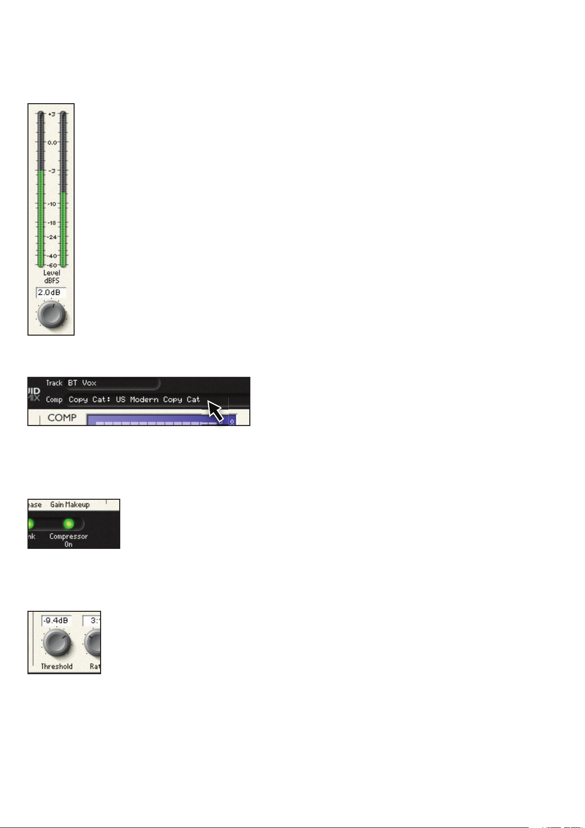
RATIO
The Ratio control determines the amount of compression applied to the signal with increasing input, and is the ratio of change in
input level compared to change in output level.
For example, if the ratio is set to 2:1, then for every 2dB of level increase on the input, the output level will increase by 1dB. For a 6dB
input increase, output increases by 3dB.
Higher ratio settings will produce more noticeable compression, so for the least noticeable result, the ratio should be set at the
minimum necessary for the application. For example, to get a certain amount of gain reduction, using low threshold and low ratio
will produce a less noticeable effect than a high threshold and high ratio, even though the total amount of compression may
be the same.
Low ratio, low threshold
High ratio, high threshold
The range of selectable ratios varies depending on the chosen compressor emulation, and the exact value is shown directly above
on the display window.
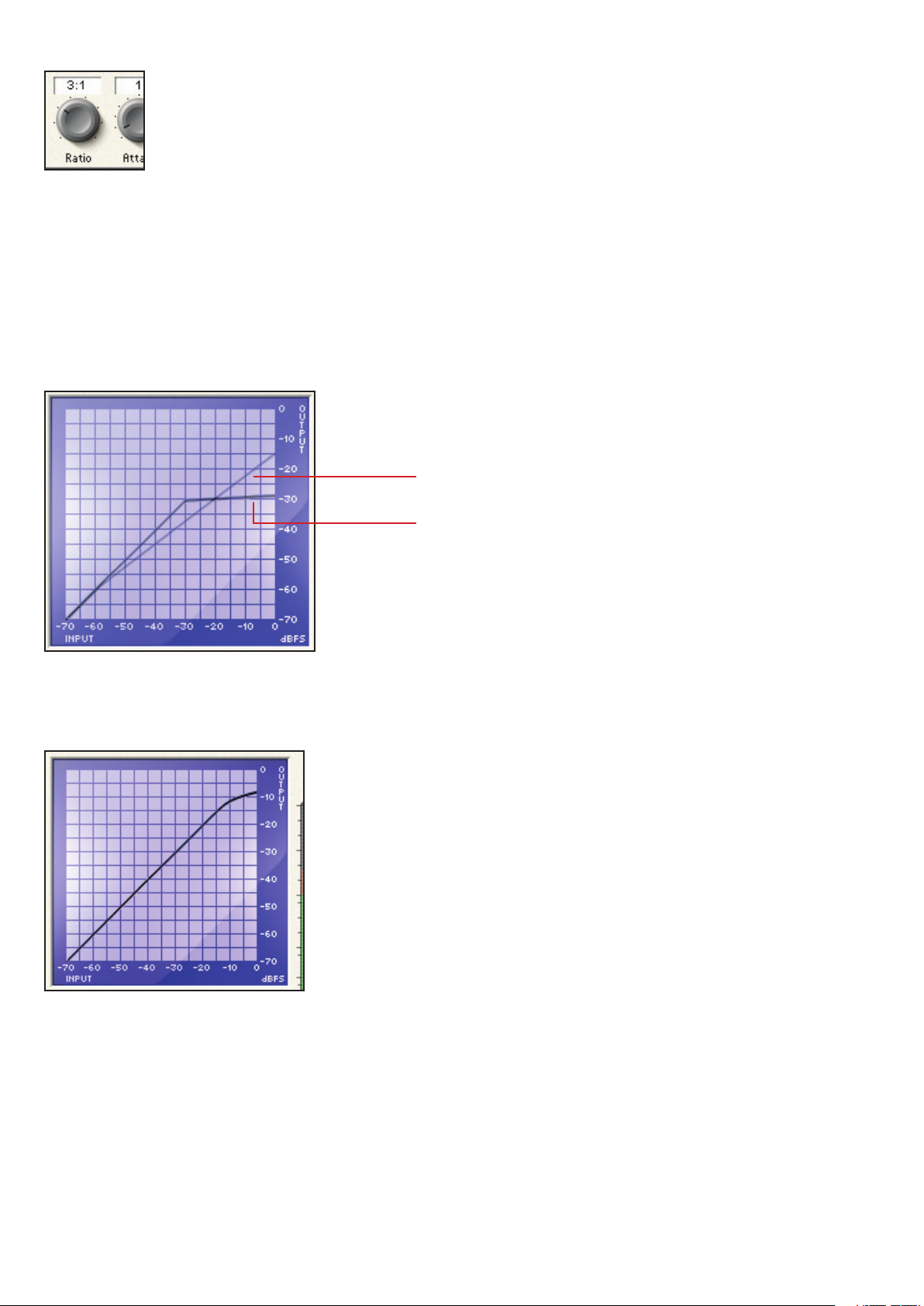
COMPRESSOR GRAPH
The compressor graph gives a graphical impression of the Threshold and Ratio settings of the selected compressor.
Note that different compressor emulations will show a different curve, depending on the performance of the original compressor
that the selected emulation is based upon. Identical threshold and ratio settings on two different compressors may not show the
same cur ve.
Page 5
5
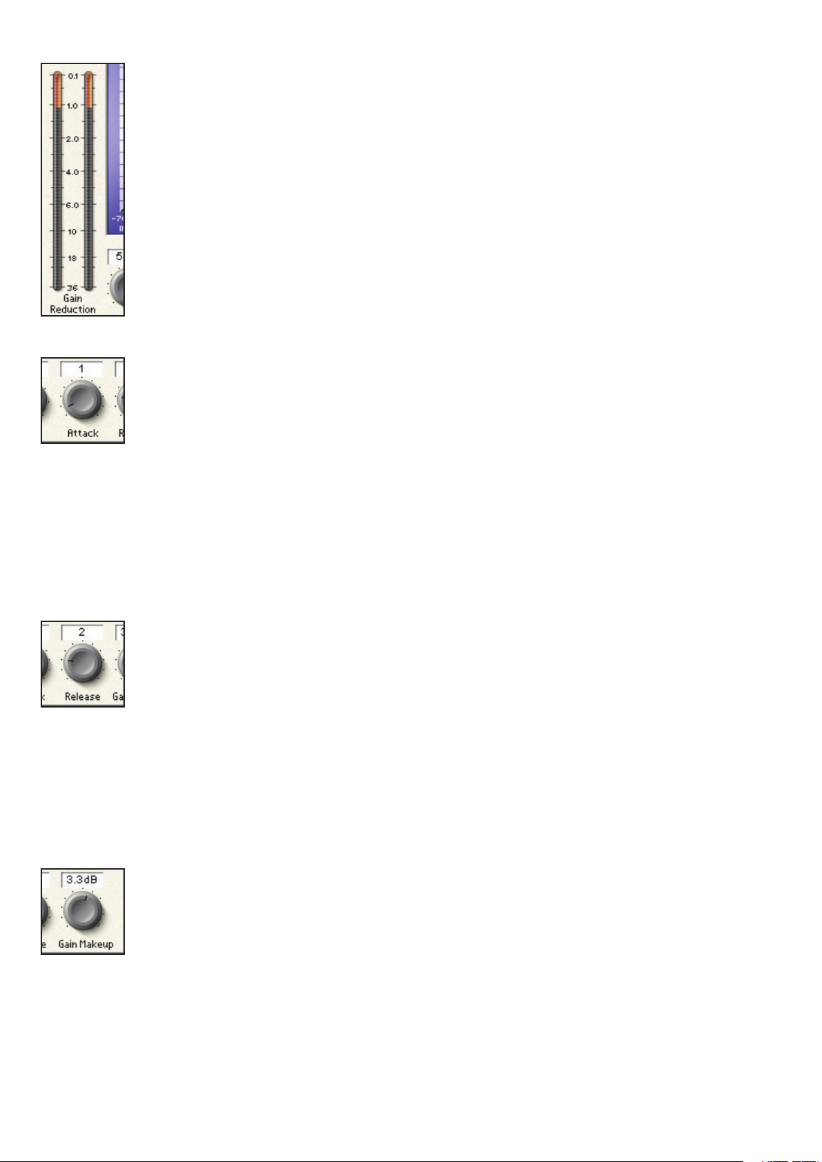
GAIN REDUCTION METER
The Gain Reduction Meter displays the amount of attenuation of the input signal by the compressor, thus
the difference in level between the output (pre gain makeup) and the input signals. Metering is in expanding
increments down to –36 dB.
ATTACK
The Attack control determines how quickly the volume is reduced once the level of the source signal has risen above the threshold.
When at low settings, the response is fast, which tends to make the compressor react to the peak levels of the signal. This is
sometimes desirable, but short transients can cause unwanted ‘pumping’ of steadier low-level signals. A slower attack will cause
the compressor to ignore short transients and respond more to the average loudness of the signal; however this may seem to
increase the relative volume of the transients. The range of selectable attack times varies depending on the chosen compressor
(unless the Free switch is active), and the exact value is shown in milliseconds (ms) on the LCD screen and directly above the dial
in the software GUI.
RELEASE
The Release control determines how quickly the volume returns once the level of the source signal has fallen below the threshold.
When at low settings, the compression releases quickly, which may be appropriate on rapidly varying signals to avoid compressing
the beats that follow, but can result in excessive distortion on more sustained material. Clockwise rotation increases the release
time, giving a smoother effect, but may also result in transients causing audible ‘pumping’. The Release time varies depending on
the chosen compressor (unless the Free switch is active), and the exact value is shown in milliseconds (mS) directly above the dial
in the software GUI.
GAIN MAKEUP
Compressing a signal will result in an overall reduction in signal level. The Gain Makeup control allows you to increase the gain of
the compressed signal. The range of selectable values varies depending on the chosen compressor, and the exact value is shown in
dB on the LCD screen and directly above the dial in the software GUI.
Page 6

6
LINK
Level detection
Gain Reduction
Device
Liquid Mix Stereo Link
Audio Input L
Left & Right
combined
Audio Output L
Control Signal
Audio Input R Audio Output R
This switch enables both Left and Right channels to be compressed equally by the linking of sidechains (see note on sidechains
below), for use when compressing a stereo signal. This switch will be active as default when a stereo instance of Liquid Mix is opened.
When compressing a stereo signal, the compression should be applied to both channels equally.
An example would be compression of a complete drum kit mix. The link switch should be enabled so if there is a loud crash cymbal
on the left hand side, then the whole level of the kit should be reduced.
If the link switch is off, then the loud crash cymbal on the left hand side will mean that the left signal is compressed more that the
right. This will have the affect of distorting the stereo imaging of the kit- as the left hand side is compressed more than the right,
then the whole kit will appear to move to the right. Deactivating the switch may be useful for more creative proposes.
What exactly is a sidechain?
A Sidechain, Trigger or Key Input are terms for the signal used to control the action of the compressor. A Sidechain can be a different
signal to the one that is actually being compressed, it can be the same signal as the one being compressed, or it can be a processed
version of the compressed signal.
When using a stereo instance of the Liquid Mix with the Link button active, then the side chain signal is the left and right input signal
combined. When using the side chain feature in Liquid Mix, the side chain is an EQ’ed version of the original signal. The Liquid Mix
does not offer the option of using an external signal for the compressor’s control signal.
Page 7

7
SIDECHAIN
The Liquid Mix is capable of taking the incoming audio signal, EQ’ing it and using the EQ’ed version of the signal to be used to activate
the compressor, but the actual compressed signal is the original non-EQ’ed version.
Activating the Sidechain Monitor switch allows the signal being fed to the sidechain to be listened to and EQ’ed. Note that while
Sidechain monitor is active, the compressor is automatically bypassed.
Once the sidechain monitor switch is active, the Liquid Mix GUI will show additional controls for EQ’ing the signal to be used as
the sidechain.
Click on the blue arrow to select the EQ type (Low Shelf, Band Pass and High Shelf). The Frequency, Gain and Q (band pass only)
can be adjusted from the 3 controls to the left of the EQ type selector.
The EQ graph will display a GREEN line indicating the frequency response created by the EQ settings.
Once the desired frequency response is selected, click on the button to the left of ‘off’ so it now reads ‘on’.
The Liquid Mix will still be outputting the sidechain monitor signal, so set the sidechain monitor button to off.
A sidechain EQ is primarily used to EQ the compressor sidechain input for a signal which has prominent or weak spectral content
at certain frequencies. De-essing vocals is a common real world example of this.
The sibilant sounds in a vocal will be in the range of 6-9kHz. De-essing aims to remove the harsh sibilant sounds from a vocal (‘S’
and ‘T’, for example) whilst minimizing the effect on the rest of the vocal sound.
Activate the sidechain monitor and use the band pass lter. Increase the gain, reduce the Q. Sweep the frequency between the
3-12kHz range to nd the sibilant frequencies that are most obvious and obtrusive (this will depend on the vocalist and vocal style).
Once you have found the correct frequency, experiment with gain and Q amount. Now you can turn on the sidechain and turn off the
sidechain monitor.
Page 8

8
FREE SWITCH
Level detection
Gain Reduction
Device
Sidechain EQ
Liquid Mix Sidechain
Audio Input Audio Output
Control Signal
Several of the vintage compressors that were sampled have fewer controls or control options than are available on Liquid Mix. As
such, in default mode, some of the controls may be inactive. This is indicated by those dials not being lit and no corresponding value
box being displayed on the screen. Similarly, if the emulated vintage unit simply had a few preset buttons or a limited range for a
particular parameter, then the Liquid Mix controls will be limited to these same settings. The Free switch in the Liquid Mix software
provides a means of simulating settings which were previously impossible with the vintage units. Activating the ‘Free’ switch allows
all the Liquid Mix compressor controls to be used for that emulation, regardless of the limitations imposed by the vintage unit. For
example, the ‘Vintage’ compressor emulation has no Ratio and Attack controls in default mode but with the Free switch active both
controls are enabled, with ranges of 1:1 to 20:1 and 0.1ms-2s, respectively. Additionally, the Release control now has a range of 1ms20s, rather than stepping through the TC (Time Constant) presets available on some of the vintage units.
COMPRESSOR POST EQ
The Compressor Post EQ Switch allows the order of processing within Liquid Mix to be reversed, positioning the EQ before
compression. Although this is not normal procedure, as compression can often squash the effects of the EQ, it is sometimes a
desirable effect. You may want to use EQ before the compressor if the compressor is not responding as you wish. For example, if the
signal is quite bass heavy, you want to remove some of the bass before the compressor, thus ensuring that the bass in the signal is
not the dominant frequency that is triggering the compressor.
Note that when the compressor is post EQ, the compressor Gain Makeup dial now controls the main output level (after both EQ and
compression). The EQ Output Gain (located under the output meters) will therefore be before the compressor.
Page 9

9
MID METER
The Mid Meter displays the level of the signal directly after the Compressor and before the EQ.
Note that when the Compressor Post EQ switch is active, the Mid Meter displays the level of the signal directly
after EQ and before compression (after the EQ Output dial).
2. EQ
This section describes all controls related to the EQ section of the Liquid Mix plugin.
EQ EMULATION SELECT
The EQ emulation can be selected by clicking in this region. Select the desired EQ emulation from the drop down list.
If no EQ emulation has been loaded, or a single band has not been highlighted, only a full emulation can be selected. If there is
already an EQ emulation loaded or a band is highlighted, a single EQ band from a full emulation can be selected for the currently
selected band.
EQ ON
Activate the EQ by clicking on the EQ On button. If no bands are currently active then this does not activate any of the EQ bands, so
bands will need to be activated individually. The EQ on button is therefore useful for being able to easily compare the signal with and
without EQ.
In order to activate all bands simultaneously, hold down the SHIF T key and click the ‘EQ On’ button on the plugin GUI. Similarly, if the
‘EQ On’ button is clicked ‘Off’ with the SHIF T key held down, then this will de-activate all the bands.
BAND ON
Pressing the Band On button will activate the corresponding band. There are separate Band On switches for each band, located
below the corresponding band’s gain, frequency and Q dials.
Page 10

10
GAIN
The Gain dial boosts or attenuates the gain of the selected band. The range and measurement units for each EQ emulation depend
upon the original EQ hardware being emulated. Note that for some band types, such as High-Pass and Low-Pass, the Gain dial will
be inactive because the only controls for such types are the frequency and occasionally resonance.
FREQUENCY
The frequency dial determines the area of the frequency spectrum that the band acts upon. Note that for some band types, such as
a 3kHz peak/notch, the Frequency dial will be inactive because that value is xed.
Q
The Q dial denes the width of the frequency band being EQ’ed. The control has an inverse function in that increasing the value
decreases the band’s spectral width. A higher Q provides a more focused, narrow band around the selected frequency whereas a
lower Q provides a wider effect over a larger frequency range.
SHAPE
Each EQ band is labeled in the Shape box. This shows whether the EQ band is a bell, shelf or hi / low pass lter shape.
If the Shape box shows a small blue arrow on the bottom right hand side, then further shape options are available for selection.
Click on the shape box to select alternative shapes from a drop down list.
Note that if the Shape box shows x1, x3, x5 etc, this indicates a multiple of the frequency range of the band. The value shown in the
Frequency box will indicate the correct (multiplied) frequency.
Refer to the Compressor and EQ Emulations Guide section for more details on Shape options for the EQ emulations.
EQ GRAPH
As an individual band is modied, its value will be displayed on the EQ graph in RED. Remember that the Band On switch must be
active for that band to have an effect, despite a curve appearing on screen.
Page 11

11
The overall EQ shape (all bands combined) will be displayed in BLACK. Whereas the line indicating a single band (Red) shows the
response of that band whether the band is active or not, the Overall EQ shape (Black) only shows the response of bands that are
active.
Note that some bands have no active controls as all values are xed. In these instances, only the Band On switch has an effect.
EQ O/P (OUTPUT)
This dial controls the overall level of the signal post EQ.
Note that when Compressor Post EQ is active, this still controls the overall level of the signal post EQ, but this will
now be pre Compressor.
The output meter shows the level of the signal directly after the EQ output dial.
Note that when Compressor Post EQ is active, this shows the level of the signal directly after the compressor make
up gain dial.
3. BUILDING A HYBRID (MIXED) EQ
In every instance of Liquid Mix, there are seven EQ bands available. These can be congured with any combination of EQ bands that
you want, using a mixture of individual bands from seven different EQ emulations or one complete 4-band emulation with three
additions and so on.
To select a band, click on any of its controls and all the bands control dials will go Red. The EQ type of the active
band is displayed in the Active box, and the Emulation from which the band came is shown in the EQ box.
Click on any control in a non-active band (i.e. one with no emulation) and all the bands controls will go Blue.
Page 12

12
With a single band selected, click in the EQ box (where the emulation name is displayed). The drop down list of emulation now
includes the option to select single bands.
Now click on another of the seven bands and repeat the process as required.
When using a hybrid EQ, this will be indicated with the words Mixed Equaliser, where as when using a single EQ emulation, this will
be indicated with the word Single Equaliser.
EQ BYPASS
Click on this button to completely bypass all EQ bands.
4. ADDITIONAL CONTROLS
GLOBAL BYPASS
Click on the bypass button to disable ALL Liquid Mix Processing of the audio signal - this includes all input and output gain stages.
Use this to compare processed and unprocessed signal.
NAMING THE LIQUID MIX PLUG-IN
Clicking in this region allows you to name the particular plug-in. This allows a quick reference when switching between Liquid Mix
plug-ins. Note that this name is separate and independent from the snapshot name.
LIQUID MIX INFORMATION
Click on the Liquid Mix logo to bring up the Liquid Mix info box, this info includes version number and plug-in latency. Click within the
info box to return to the normal plug-in view.
LIMIT AND CLIP LIGHTS
The Limit Light (although directly above the input meter) actually applies to the signal level directly PRE EQ. The EQ cannot process
the input signal correctly if it is to high, therefore the signal will be hard limited. If this light is lit, either reduce the compressor
make up gain, or, when Compressor is post EQ, reduce the input gain.
The Clip Light indicates if the output signal level will clip your DAW’s internal mixer. Some DAWs clip at 0dBFS, other DAWs use
oating point, so will never clip. Check your DAW’s documentation for specifcations.
Page 13

13
5. SNAPSHOTS - SAVING & LOADING LIQUID MIX SETTINGS
Liquid Mix settings, like with any other plug-in, will be saved within the project le when you save the project from your host DAW
software. You can also save presets using your host’s own save preset functionality.
The Liquid Mix allows you to save the settings from the Liquid Mix GUI in a host independent format. This method of saving settings
has some benets over using your host’s own method (see below).
Liquid Mix settings les are called ‘Snapshots’. Saving a snapshot means that a combination of compressor and EQ can be recalled
at any point.
A saved snapshot can be used:
- On a different track within your project
- In a different project
- In a different DAW
- In a DAW using a different plug-in format type (for example, a snapshot saved in VST system can be loaded in a TDM system
- Cross platform i.e. Mac to PC, PC to Mac
- To reload compressor or EQ settings individually
- To upload to the Liquid Settings area on the Focusrite website to share with other Liquid Mix users
http://focusrite.com/support/
To save a snapshot from the software, click on the oppy disk image in the top right of the software window then select
‘Save Snapshot’ from the drop down list.
This will open a window where you can name your snapshot and save it in any location on the computer.
Liquid Mix snapshot les will have the extension ‘.lss’
It is advisable to save this le in the following default location:
MAC OS
Mac HD – Library – Application Support – LiquidMix
WINDOWS
C:\Documents and Settings\”your username”\ Application Data\LiquidMix *
*Note: If you are using a non-English version of XP or if you run your Program Files on a drive other than the
C:\ drive, your paths will be different. EG: If you are running on the D:\ drive, replace C:\ with D:\ in the path.
Once the snapshot has been named and saved, you will see the name displayed in the snapshot window.
To rename a snapshot, click on the disk image in the top right of the software window, select Rename Snapshot, then click on the
Snapshot box, type in a new name and press enter.
Page 14

To load a snapshot from the software, click on the oppy disk image and then select Load Snapshot from the drop down list.
From Load Snapshot, you can choose to load the full snapshot (Compression and EQ), Compressor Only (thus retaining your current
EQ settings), or EQ only (thus retaining your current Compressor settings)
A window will then appear, allowing you to navigate to the snapshot anywhere on your computer.
E & O.E.
14
 Loading...