

Page 1

ENG LISH
1
LiquidControl™ Software
Please visit www.focusrite.com to download the latest version of the free LiquidControl™
software application, for Mac OS X or Windows XP. The application allows you to edit The
Liquid Channel™ remotely, plus load, save and archive the mic-pre and compressor replicas
and programs. The LiquidControl™ user guide is also available to download in PDF format.
Contents
Introduction ............................................................................ 1
Important Safety Instructions ............................................. 1
Power Connections.............................................................. 1
Liquid Channel™ Architecture ......................................... 2
Rear Panel Connections ......................................................3
Front Panel Controls............................................................ 3
Mic-Pre and A/D.................................................................... 4
Session Saver ..........................................................................4
Clock Select and Synchronisation..................................... 5
Main LCD and Controls ...................................................... 5
Harmonics ............................................................................... 6
Compressor Settings............................................................ 6
3-Band EQ ............................................................................... 7
Comp & EQ Settings ............................................................8
Data Select .............................................................................. 8
Linking Multiple Units.........................................................10
Connections and Applications .........................................11
Frequently Asked Questions............................................16
Specifications ........................................................................21
Disclaimer .............................................................................22
Accuracy ................................................................................ 22
Copyright ..............................................................................22
Warranty ............................................................................... 22
Introduction
Thank you for purchasing The Liquid Channel™
brought to you by the Focusrite team – Ian, Trevor,
Peter, Martin, Tom, Mick A’C, Phil, Chris G, Micky,
Pauline, Melissa, Chris W, Rob J Snr, Simon J, Vernon,
Giles, Rob J Jnr, Mick G, Tim, Dave, Nick, Paul, Peter
and Simon.
The chaps at Focusrite are a jolly hard working bunch
and take a great deal of pride in designing, building and
delivering products which are considered the best
audio units around; we hope your new Focusrite unit
lives up to that reputation and that you enjoy many
years of productive recording. If you would like to tell
us about your recording experiences then email us at:
sales@focusrite.com
The Focusrite Team
Important Safety Instructions
Please read all of these instructions and save them for future
reference. Follow all warnings and instructions marked on
the unit.
• Do not obstruct air vents in the rear panel. Do not
insert objects through any apertures. Ensure adequate
ventilation at all times.
• Do not use a damaged or frayed power cord.
• Unplug the unit before cleaning. Clean with a damp
cloth only. Do not spill liquid on the unit.
• Unplug the unit and refer servicing to qualified service
personnel under the following conditions: if the power
cord or plug is damaged; if liquid has entered the unit; if
the unit has been dropped or the case damaged; if the
unit does not operate normally or exhibits a distinct
change in performance. Adjust only those controls that
are covered by the operating instructions.
• Do not defeat the safety purpose of the polarised or
grounding type plug. A polarised plug has two blades
with one wider than the other. A grounding type plug
has two blades and a third grounding prong. The wider
blade or the third prong are provided for your safety.
When the plug provided does not fit into your outlet,
consult an electrician for replacement of the obsolete
outlet.
This unit is capable of operating over a range of mains
voltages as marked on the rear panel. Ensure correct mains
voltage setting and correct fuse before connecting mains
supply. Do not change mains voltage settings while mains
supply is connected. To avoid the risk of fire, replace the
mains fuse only with the correct value fuse, as marked on
the rear panel. The internal power supply unit contains no
user serviceable parts. Refer all servicing to a qualified
service engineer, through the appropriate Focusrite dealer.
WARNING:
THIS UNIT MUST BE EARTHED BY THE
POWER CORD. UNDER NO
CIRCUMSTANCES SHOULD THE MAINS
EARTH BE DISCONNECTED FROM THE
MAINS LEAD.
Power Connections
There is an IEC mains lead supplied with the unit, which
should have the correct moulded plug for your country. The
wiring colour code used is:
For units shipped to the USA, Canada, Taiwan and Japan:
Live Black; Neutral White; Earth Green
For units shipped to any other country:
Live Brown; Neutral Blue; Earth Green & Yellow
Page 2

ENG LISH
2
Liquid Channel™ Architecture
The Liquid Channel™ is fundamentally different from
any other Focusrite product previously built – and
indeed any other dynamics processor currently
available. Although The Liquid Channel™ is extremely
simple to use, please take a moment to read this
section of the user guide, which gives a brief overview
of the signal path and storage capabilities of the unit.
Overview
The Liquid Channel™ is the first implementation of
Focusrite’s groundbreaking ‘Liquid Technology’. The
Liquid Channel™ transports classic front-end
processing into the digital age, removing the need for
endless patching and adding fluidity and reliability to
the studio environment. Quite simply, The Liquid
Channel™ is capable of being configured to replicate
the finest mic-pres and compressors in history, all
inside a single 192 kHz, 2U device.
This is achieved through a unique two-part process.
Firstly, the use of Dynamic Convolution techniques is
applied, utilising lightning fast SHARC chips applying
unique level-dependent impulse responses to every
sample of audio. However, whilst this is more than
sufficient to closely emulate a compressor’s sonic
behavior, in order to replicate subtle nuances of
classic units, the pre-amplifier must operate in a
suitable physical environment to mirror the way in
which any classic unit interacts with a given
microphone. The Liquid Channel™’s solution to this
problem lies in its vast analogue front-end. The preamp has the ability to change its impedance and vary
its signal path to either transformer or electronic,
replicating the interaction characteristics of the
original, whilst remaining transparent within the signal
path.
The Liquid Channel™ can therefore closely replicate
the sound of the classic mic-pres and compressors
from history. With entirely digital front panel controls,
all parameters can be saved in one of 100 program
memories, meaning that entire session setups can all
be recalled at the touch of a button. A brand new
digital EQ is also available, providing a comprehensive
and truly ‘liquid’ channel strip.
A USB connection on the rear panel links to the
LiquidControl™ software application, enabling the
archiving of both replicas and surplus program
memories, as well as providing full editing and remote
operation of the unit itself. The Liquid Channel™
comes complete with replicas of 40 classic mic-pres
and forty classic compressors but is infinitely
expandable, since the USB port also facilitates the
upload of further replicas downloaded from a
dedicated website –
www.focusrite.com.
Finally, to account for variances in amounts of second,
third and fifth order harmonic distortion (usually
perceived as warmth) from one pre-amp to the next, a
dial is included to permit control over this value. This
essential feature ensures satisfaction for even the most
hardcore vintage enthusiast, bringing accurate control
over the key sonic attributes.
Liquid Assets
The Liquid Channel™ ships with 40 pre-amp replicas
and 40 compressor replicas as standard. The free
LiquidControl™ software allows additional replicas
downloaded from
www.focusrite.com to be
uploaded to The Liquid Channel™ via USB.
Program memories
The Liquid Channel™ has 100 program memories to
allow storage of preferred pre-amp/compressor/EQ
combinations. These can be saved, archived and
reloaded from a remote computer using
LiquidControl™ via the USB connection. All channel
parameters are stored, offering ‘total recall’ including
mic gain. Using LiquidControl™, a virtually unlimited
number of replicas and programs can be stored on
your PC or Mac and uploaded to The Liquid
Channel™ hardware as required. You can also email
your favourite Liquid Channel™ replicas and program
settings to other users anywhere in the world – the
ultimate in session recall.
Signal Path
The Liquid Channel™ features both analogue (mic and
line) and digital (AES-EBU) inputs, plus analogue (line)
and digital (AES-EBU) outputs. Analogue signals
connected to the mic input are routed through an
analogue mic-pre stage, before passing through an A/D
and entering the digital pre-amp convolution section.
The unique sonic characteristics of the selected preamp replica are then applied to the signal. The signal
then passes through the compressor and EQ sections
(in that order, unless the EQ ‘Pre Comp’ switch has
been engaged – see page 7 for details). This processed
signal then routes to the digital output, and via the
D/A to the analogue output.
Analogue signals connected to the line input follow the
same signal path as above, but bypass the initial micpre stage routing directly to the A/D. The pre-amp
type will be fixed at FLAT trfmr (transformer) whilst
the line input is selected on the front panel. Digital
signals connected to the digital input are routed
directly to the pre-amp convolution section. However
this can be bypassed – see ‘Pre-amp and Compressor
Select’ on page 5 for details.
Page 3
ENG LISH
3
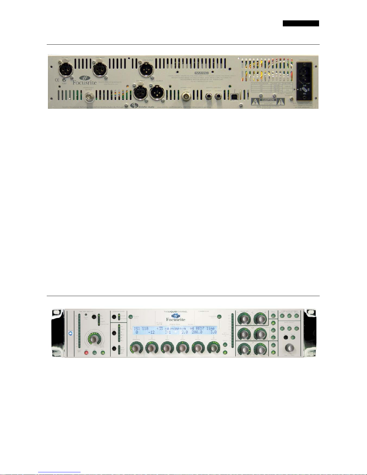
Rear Panel Connections
XLR Audio Inputs and Output
All 3-pin XLR audio connectors (MIC I/P, LINE I/P and
LINE O/P – from left to right above) are wired as
follows:
Pin 1: Screen/Chassis
Pin 2: Audio 0°
Pin 3: Audio 180°
AES Input and Output
The AES I/P and AES O/P XLR connectors provide
The Liquid Channel™ with AES-EBU format digital
input and output. See pages 11-15 for details of digital
applications and connectivity.
Wordclock Input and Output
The WORDCLOCK INPUT BNC connector allows
The Liquid Channel™ to be linked to an external
clock source. The WORDCLOCK OUTPUT BNC
connector allows The Liquid Channel™ to supply a
clock source to external equipment. See page 9 for
more details on synchronising The Liquid Channel™
to an external Wordclock source.
Dynamic Link Bus
The DYNAMIC LINK BUS connectors allow two or
more units to be linked together for stereo and multichannel applications, whereby one unit (the ‘master’)
will control the settings on multiple units. In addition,
if using multiple units in digital stereo pairs, the
dynamic link connectors also transmit digital audio
data between devices. The connectors are both RCA
(phono). See page 10 for more details on linking
multiple units.
USB
The USB connector allows The Liquid Channel™ to
be connected to a computer running the free
LiquidControl™ software, which allows remote
operation, download and archive management. See the
separate LiquidControl™ user guide, downloadable
from
www.focusrite.com, for more information. For
remote operation at a greater distance (up to 45m),
contact Focusrite for information about purchasing a
USB to CAT5 (Ethernet) converter.
Front Panel Controls
Digital controls
The dials are all tactile rotary encoders, meaning that
they can be rotated infinitely and their relative value
will be displayed (except for the DATA wheel) by the
LEDs surrounding them. The exact numerical
parameter values can be seen on the large display
when active, in the centre of the front panel.
As all controls are digital, the settings can be saved
and recalled with ease, and edited from the
LiquidControl™ software application (please see the
separate LiquidControl™ documentation, available
from
www.focusrite.com for details). N.B. The
hardware's onboard memory will store the last frontpanel settings to have been left standing on the unit
for over 10 seconds while powered up, while the unit
is turned off.
Page 4
ENG LISH
4
Power
Applies power to the unit. Turn on The Liquid
Channel™ before powering up devices to which the
outputs are connected.
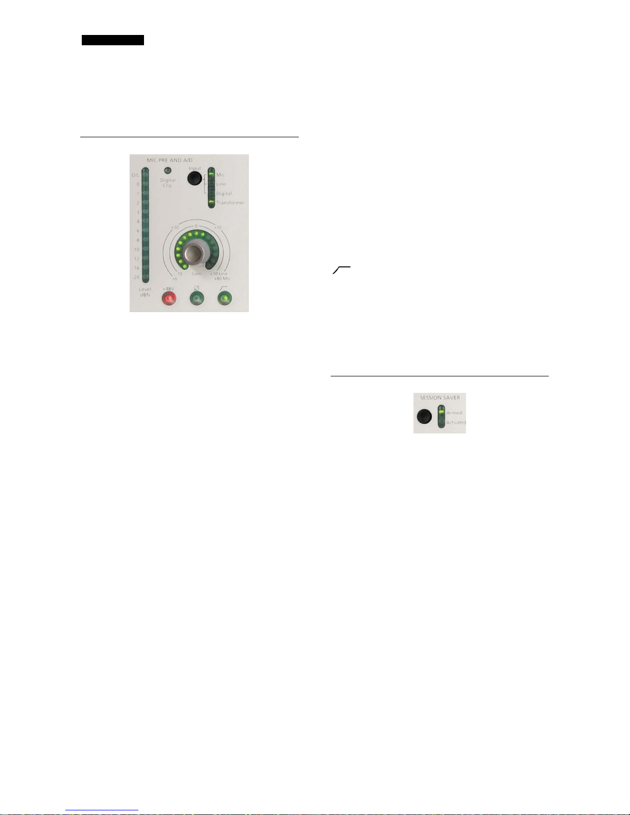
Mic-Pre and A/D
Meter
A single, vertical, peak hold LED bar graph displays the
level of the signal being fed from the mic-pre to the
A/D converter, controllable by the gain dial in the micpre section. The scale shows from –20 dBFS up to the
maximum 0 dBFS (digital clipping level) with an
additional LED to represent overload (O/L). Exceeding
this maximum will result in the A/D clipping the signal,
which may cause audible and unwanted distortion.
Digital Clip LED
A single separate red LED is also included to signify
when a digital clip is occurring.
Input Select
The input Select switch, pressed repeatedly, will step
through the mic, line and digital inputs, with an LED
beside each, which illuminates when that input is
active. A further LED is provided to show when the
transformer has automatically been switched in circuit;
this will change according to the mic-pre replica
selected.
Gain dial
The dial below the input select switch adjusts the level
fed to the A/D. The levels for mic and line are shown
by the outside (mic) and inside (line) arc around the
dial, with the exact numeric value displayed next to
the pre-amp replica name on the front panel LCD
(indicated by ‘Pre-amp Gain dB’).
+48V
Pressing the +48V switch provides +48V phantom
power, suitable for condenser microphones, to the
rear panel XLR microphone connector. This switch
does not affect the other inputs.
If you are unsure whether your microphone requires
phantom power, refer to its handbook, as it is possible
to damage some microphones (most notably ribbon
microphones) by providing phantom power.
Ø
Pressing Ø inverts the phase of the selected input,
primarily used to correct phase problems when using
multiple microphones on a single source.
This switches an analogue, pre-A/D high-pass filter
into the signal path, in order to roll off low
frequencies. This is switchable (in the Setup menu)
between a 75 Hz and 120 Hz roll-off. See page 9 for
more information about the Setup menu. The roll-off
is 12 dB per octave, 6 dB down at 75 or 120 Hz.
Session Saver
Next to the Mic-Pre and A/D section and above the
Clock Select switch is the Session Saver switch. Press
this switch once to arm the Session Saver. Once this
circuit is armed (indicated by the corresponding LED)
a gain reduction will occur if the signal starts to clip.
This is a way of protecting your session from continual
overload if the level is consistently ‘hot’.
The Session Saver’s action is different from a limiter’s
action, as the signal isn’t compressed in any way, just
turned down by an appropriate amount to avoid
overloading. The feature monitors the signal at the
input and output. If the input is overloading, the micpre gain is reduced. If the output is clipped but the
input is clean, the level of the makeup gain is lowered.
When the section has reduced the gain, the Activated
LED will illuminate. Once the level is decreased, it
remains activated until the switch is pressed to disarm
the Session Saver. Pressing once more will then rearm the Session Saver.
Page 5
ENG LISH
5
Clock Select and Synchronisation
Clock Select
This switch changes the clock to the sample rate value
indicated by the corresponding LED: 44.1 kHz, 48
kHz, 88.2 kHz, 96 kHz, 176.4 kHz or 192 kHz. If using
an external digital input, the sample rate must be set
to match that of the digital signal fed to the input.
Ext
This switch allows The Liquid Channel™ to
synchronise to an external source, either the
Wordclock or AES input on the rear panel, each
shown by an LED. When a lock is achieved, the
corresponding LED will illuminate. If the LED flashes
the unit is not locked and jitter will be evident.
N.B. If either Wordclock or AES are selected and
there is no cable connected to the relevant input, The
Liquid Channel™ will not achieve lock.
When processing in 176.4 or 192 kHz, The Liquid
Channel can accept and regenerate either 88.2/176.4
kHz or 96/192kHz respectively, depending on the
clock source and destination requirements. See the
Setup menu section on page 9 for more details.
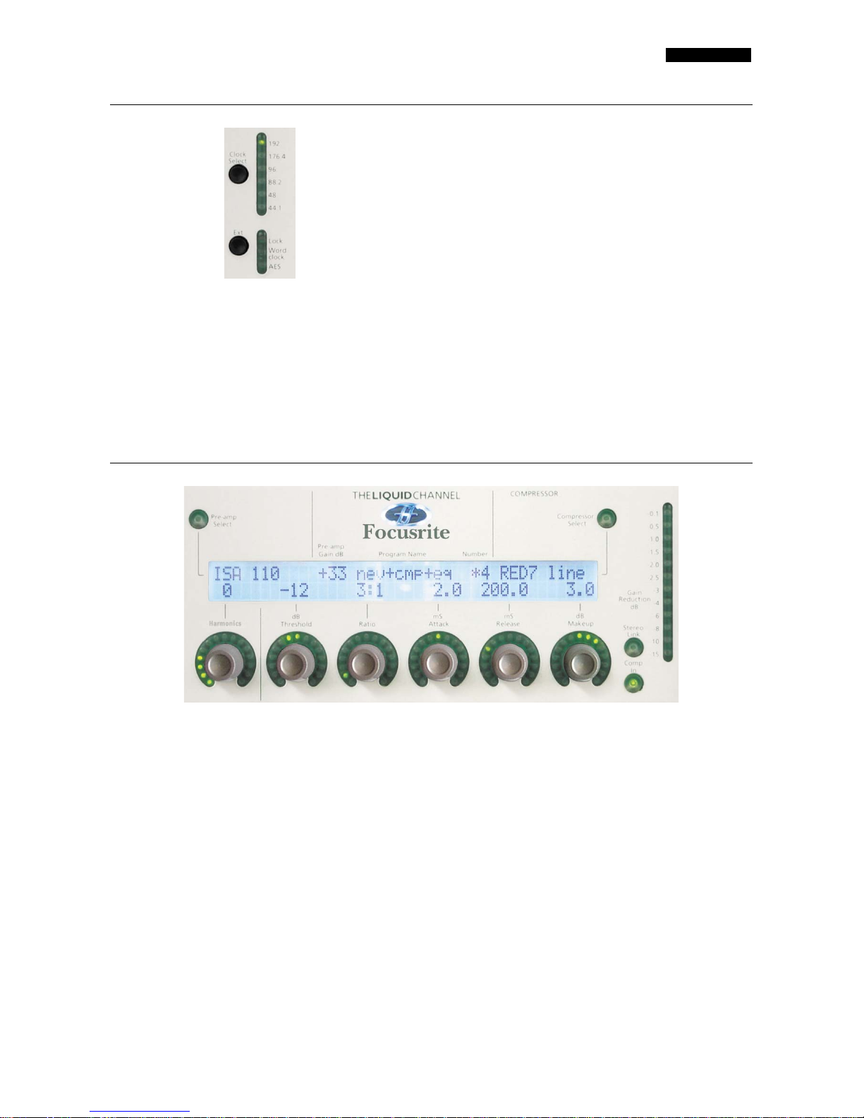
Main LCD and Controls
Pre-amp Gain DB
This area of the display shows the gain (as set using
the Gain control in the Mic-Pre and A/D section) in
dB.
Program Name
This area of the display shows the name of the
currently loaded program memory. Naming and saving
of programs are separate commands; it is advisable to
name the program first, then save it.
Number
This area of the display shows the number of the
currently loaded program memory, from 00-100.
Selecting ‘00’ allows the user to return to the factory
default program memory, which always loads the
‘FLAT trfmr’ mic-pre and ‘FLAT comp’ compressor.
Unlike program memories 01-100, program memory
00 cannot be overwritten.
Pre-amp and Compressor Select
When beginning a session for the first time, it is
recommended to load default program 00 (see above),
as this is an ideal starting point.
Pressing the Pre-amp Select switch causes its LED to
flash. Rotating the DATA wheel then allows a
microphone pre-amp replica (shown in the top left
hand corner of the display window) to be selected by
scrolling through a bank of pre-amp replicas. When
the desired pre-amp is found, press the DATA wheel
once to load the required pre-amp replica.
N.B. To use The Liquid Channel™ as a standalone
compressor with an analogue input, select the Line
input, which will automatically select the transparent
Page 6

ENG LISH
6
‘FLAT trfmr’ (transformer) input stage. To use The
Liquid Channel™ as a standalone compressor with a
digital input, you can select the ‘FLAT dig’l’ pre-amp
on the front panel.
Pressing the Compressor Select switch causes its LED
to flash. Rotating the DATA wheel then allows a
compressor replica (shown in the top right hand
corner of the display window) to be selected by
scrolling through the bank of compressor replicas.
When the desired compressor is found, press the
DATA wheel once to load the required compressor
replica.
N.B. Loading a new mic-pre or compressor will not
affect any values dialled in on the front panel. For
example, if the user changes a compressor’s threshold
value from –7 dB to –9 dB and then loads a new
compressor replica as above, that new compressor
replica’s threshold value will initially be –9 dB. (If ‘As
Original Model’ is selected in the Setup menu (see
page 9) the value will reset to the nearest available
value.) To save all edited values when you have
finished editing so that they may be recalled later, use
the Save switch (see page 8).
Harmonics
The dial directly below the pre-amp name allows
desirable harmonic distortion, perceived as ‘warmth’,
to be applied. The exact amount of 2nd-, 3rd-and 5thorder harmonics depends both on the type of preamp chosen and the amount of mic-pre gain. This is
because the amount of each harmonic with respect to
each other is different for pre-amps with valves
compared to those with transformers; and also
because the balance of harmonics changes with level.
This means that a higher gain at the mic-pre stage will
result in a greater, and hence more noticeable, effect
as the harmonics setting is increased. Special ‘hot’
replicas, which can be downloaded from
www
.focusrite.com, provide greater levels of harmonics
application, for those wanting to achieve a seriously
overdriven sound.
The harmonics control allows replication of the subtle
variations between analogue devices, (sometimes two
units of the same type can have different amounts of
harmonic distortion), and allows the user to create an
‘overdriven’ sound without having to overdrive the
pre-amp. Careful use of the Harmonics control will
thus allow the user to ‘tune in’ The Liquid Channel™
replicas to their own individual vintage unit.
The amount of harmonic distortion is indicated by the
LEDs surrounding the dial and a value from 0-15
shown above it. ‘+ODD’ appears next to the value
when third and fifth order harmonics are present.
Compressor Settings
N.B. If the Compressor Controls option in the Setup
menu has been set to ‘As Original Model’, then
depending on the compressor replica selected, not all
of the following settings may be available. With ‘As
Original Model’ selected, only those controls that
were present on the original unit are available for
editing, all other dials display ‘FIXED’ and are inactive.
Similarly, if the dials’ values are reversed on the
original or they have some special operational
features, then these are also replicated on the front
panel. See page 9 for more information on the Setup
menu.
Comp In
The compressor is activated by pressing the Comp In
switch, located in the bottom right corner of the
middle section.
Threshold
The Threshold control sets the level at which
compression begins. The lower the threshold, the
more the signal is compressed. Setting a higher
threshold allows quieter passages in the music or
speech to remain unaffected; only passages that
exceed the threshold will be compressed. The level of
threshold varies depending on the chosen
compressor, and the exact value is shown in dB
directly above the dial on the display window.
Ratio
The Ratio control determines the amount of
compression applied to the signal with increasing
input, and is the ratio of change in input level
compared to change in output level. Higher ratio
settings will produce more noticeable compression, so
for the least obtrusive result, the ratio should be set
at the minimum necessary for the application. For
example, using low threshold and low ratio will
produce a less subjectively noticeable effect than a
high threshold and high ratio, even though the total
amount of compression may be the same. The range
of ratios selectable varies depending on the chosen
compressor replica, and the exact value is shown
directly above on the display window.
Page 7

ENG LISH
7
Attack
The Attack control determines how quickly
compression is applied once the level of the source
signal has risen above the threshold. When turned
anti-clockwise the response is very fast, which tends
to make the compressor react to the peak levels of
the signal. This is sometimes desirable, but short
transients can cause unwanted ‘pumping’ of steadier
low-level signals. A slower attack will cause the
compressor to ignore short transients and respond
more to the average loudness of the signal; however
this may seem to increase the relative volume of the
transients. The range of attack times selectable varies
depending on the chosen compressor, and the exact
value is shown in milliseconds (mS) directly above on
the display window.
Release
The Release control determines how quickly
compression is removed once the level of the source
signal has fallen below the threshold. When in the
anti-clockwise position, the compression releases very
quickly, which may be appropriate on rapidly varying
signals to avoid compressing the beats that follow, but
can result in excessive distortion on more sustained
material. Clockwise rotation increases the release
time, giving a smoother effect, but may also result in
transients causing audible ‘pumping’. The Release time
varies depending on the chosen compressor, and the
exact value is shown in milliseconds (mS) directly
above on the display window.
Makeup
Compression results in an overall reduction in level.
The Makeup control allows you to increase the gain of
the compressed signal. The range of makeup values
selectable varies depending on the chosen
compressor, and the exact value is shown in dB
directly above on the display window.
Stereo Link
This switch enables Liquid Channel™ units to be
linked, so that the ‘master’ can control multiple ‘slave’
units. To set whether the unit is the ‘master’ or ‘slave’,
the Setup menu must be accessed. See page 9 for
more information on the Setup menu, and page 10 for
more information on linking multiple units.
Gain Reduction bar graph
The vertical LED meter indicates the action (Gain
Reduction) of the compressor, in expanding
increments down to –15 dB.
3-Band EQ
The Liquid Channel™ features a new digital
(‘modelled’ rather than ‘convolved’) EQ, loosely based
on the classic Focusrite sound of the original ISA 110.
This is designed to allow small amounts of corrective
shaping. All of the EQ settings can be saved, along with
those of the mic-pre and compressor, in one of the
Program slots (see the DATA SELECT section below).
EQ In
Located in the bottom right corner of the section, this
switch activates the EQ section and is illuminated
when the EQ is active.
Pre Comp
Pressing this switch (illuminated when active) allows
the EQ to be moved to a position prior to the
compressor in the signal path.
Show Value
Pressing this switch (illuminated when active) causes
the exact values of each EQ dial to be shown in the
display window, for more visual accurate parameter
modification.
High-frequency shelving
The two upper dials control the frequency (left dial)
and gain (right dial) of the high-frequency shelf. The
frequency varies from 200 Hz to 20 kHz, and the gain
between –18 dB and +18 dB.
Low-frequency shelving
The two lower dials control the frequency (left dial)
and gain (right dial) of the high-frequency shelf. The
frequency varies from 10 Hz to 1 kHz, and the gain
between –18 dB and +18 dB.
Page 8

ENG LISH
8
Parametric mid-band
The two dials in the centre control the frequency (left
dial) and gain (right dial) of the parametric mid-band.
The frequency varies from 100 Hz to 10 kHz, and the
gain between –18 dB and +18 dB.
Hi Q
This switch (illuminated when active) changes the Q
to a higher value, causing the parametric controls to
affect a narrower band of frequencies. With Hi Q
switched out the Q value is 0.8. With Hi Q switched
in the value is 2.5.
Sidechain EQ
This switch (illuminated when active) routes the
parametric mid-band EQ section to the sidechain of
the compressor for frequency-conscious compression.
Use this to configure the compressor to compress
some parts of the frequency spectrum more than
others, for example when de-essing.
N.B. The high- and low-frequency shelving bands will
still be active in the audio path, and will still be
affected by the Pre Comp switch (see above) if
engaged.
Sidechain Listen
This switch (illuminated when active) allows the
sidechain to be monitored independently, allowing
easy setup of frequency-conscious compression.
Release the switch when setup is complete.
Comp & EQ Settings
Bypass
This switch (illuminated when active) allows the user
to hard bypass the harmonics, compressor and EQ
sections.
Compare
This switch allows the user to temporarily revert back
to the saved program memory settings, allowing an
A/B comparison between the saved and adjusted
session setups. Press the switch once to revert to the
saved program memory settings, and a second time to
return to the currently edited settings.
Revert
Having used the Compare switch to qualify new
settings, should the original (saved) program
parameters be preferred, then this switch can be
pressed to revert to the previously saved settings.
N.B. Any edits made to the program
settings will then be permanently lost.
Wordclock and phantom power settings are not saved
in the unit’s Program memories.
Data Select
This section is responsible for managing Program data,
saving, naming and recalling sessions.
DATA
Rotating this dial allows the pre-amp or compressor
replicas to be chosen (when the Pre-amp Select or
Compressor Select switches are activated) and allows
various parameters to be modified or selected in the
DATA SELECT section. To choose a parameter,
once found, press the DATA wheel in once.
Save
Pressing this switch allows the current session setup
(all front panel controls) to be saved to an allocated
program memory slot. Once the Save switch has been
pressed and is flashing, the DATA wheel will scroll
through the 100 program memories. When the
relevant space is found (this may be an already named
slot or an empty one) pressing the DATA wheel will
save the settings. Press the Save switch again to cancel
(without pressing the DATA wheel). When a
parameter is changed on a saved program, a star will
appear next to the Program number, showing the user
that the Program has been edited and may need to be
saved.
N.B. If you overwrite another program
memory, that memory will be lost.
If you run out of spare program memories, the
LiquidControl™ application allows you to store an
unlimited number of programs on your Mac or PC and
upload them to The Liquid Channel™ as required. See
the LiquidControl™ documentation for details.
Page 9

ENG LISH
9
Recall
This switch allows a program memory to be loaded,
recalling all settings for a particular session. Once the
Recall switch has been pressed and is flashing, the
DATA wheel will scroll through the 100 program
memories. When a relevant program memory is
found, pressing the DATA wheel will load the
program memory. Press the Recall switch again
immediately to cancel (without pressing the DATA
wheel). Wordclock and phantom power settings are
not saved in the unit’s Program memories.
Name
This switch enables program memories to be named.
Once the Name switch has been pressed and is
flashing, the letters can be adjusted. Rotating the
DATA wheel changes the current letter/symbol and
pressing it moves on to the next character. When
the program memory name is completed,
the program will need to be saved (unless
already done). See the Save section above.
Clear
When in Name mode, this switch erases all
characters, to allow a new name to be entered from
scratch. (Clear does not affect any other program
settings.)
Setup
This menu allows various Liquid Channel™ settings to
be adjusted. The DATA wheel scrolls through options
when rotated, and will save the setting and move on
to the next screen when pressed. Press the Setup
switch once to exit. The Setup menu options are:
LF Filter
Use the DATA wheel to select a cut-off frequency of
75 or 120 Hz for the LF filter (see Mic-Pre and A/D
section on page 4 for details of the LF filter).
Compressor Controls
This option allows the user to specify whether or not
the compressor control ranges are restricted to those
of the original units being replicated. Use the DATA
wheel to select ‘As Original Model’ or ‘FREE’.
Selecting ‘FREE’ allows you to create new settings that
were not possible on some original units.
Wordclock Input
If using the unit’s digital input, running at 176.4 or 192
kHz and the Ext sync switch is set to wordclock input,
then the unit can be set to lock to 88.2/176.4 kHz or
96/192 kHz respectively, depending on the clock
source.
Wordclock Output
If using the unit’s digital input and running at 176.4 or
192 kHz, the unit’s wordclock output can be set to
regenerate 88.2/176.4 kHz or 96/192 kHz
respectively, depending on the clock destination.
Digital Link Bus (Gain Linkage)
If using more than one Liquid Channel™, this setting
specifies how many machines are to be linked. Up to
eight Liquid Channels may be chained via the DIGITAL
LINK BUS connectors. See page 10 for more
information about linking multiple units. If using
only one unit, ensure this is set to ‘OFF’.
Gain Linkage
If Digital Link Bus has been set to a value greater than
‘OFF’ (see above), this setting specifies whether The
Liquid Channel™ is to act as the master or slave.
With more than two units connected, each slave
machine must be identified with a unique number,
from 2 to 8. The available options are machine #1
(master) and machine #2 – #8 (slave). N.B. This
option is only available when Compressor Gain
Linkage is set to a number greater than ‘OFF’.
Slave Controls to Master
If The Liquid Channel™ unit has been set up to slave
to another master Liquid Channel™ unit, a ‘Slave
Controls to Master’ menu will appear. Using the
DATA wheel, the user may select ‘Yes’ or ‘No’.
Selecting ‘Yes’ will cause the slave Liquid Channel™
unit’s controls to follow any changes made to the
master Liquid Channel’s controls. (The slave unit’s
controls become inactive.) Mic-pre and compressor
replicas called up on the master unit will also be called
up on the slave unit(s.) This is the standard setup for
most linked applications.
Selecting ‘No’ will allow the user to continue to edit
the slave’s controls independently, even though the
master and slave units’ gain reductions are linked.
Hence selecting ‘No’ allows the user to independently
set up e.g. mic-pre gain levels, compressor ratios etc.
independently on a slaved unit.
AES Linking
If the Digital Link Bus is not set to ‘OFF’, then an AES
Linking option will appear in the Setup menu. This
allows multiple Liquid Channels™ to be used as
grouped AES pairs, by sending both units’ signals down
a single wire (as in diagram 5 on page 12).
There are three possible settings:
• Both units are receiving analogue signals and the
master is sending AES – set master to ‘Link AES –
right: from slave’ – and set slave to ‘Link to
master AES – right: output’.
• Both units are receiving analogue signals and the
slave is sending AES – set master to ‘Link AES –
right: to slave’ – and set slave to ‘Link to master
AES – right: input’.
• The master is receiving AES and sending AES –
set master to ‘Link AES – right: to and from
slave’ – and set slave to ‘Link to master AES –
right: in and out’.
Page 10

ENG LISH
10
USB ID
This setting allows the USB ID to be set between 1
and 8. When using the LiquidControl™ software
application with multiple Liquid Channel™ units, each
unit must be assigned a unique USB ID to allow it to
be selected in the LiquidControl™ application. Turn
the DATA wheel to change the USB ID value and
press the DATA wheel once to enter the selected
value. See the downloadable LiquidControl™
documentation for more information.
Linking Multiple Units
Using the DIGITAL LINK BUS connectors, up to eight
Liquid Channel™ units may be linked, so that one
‘master’ unit controls the compressor, mic-pre gain
and other parameters of all connected ‘slave’ units.
This means you can use multiple Liquid Channel™
units for perfectly matched stereo or multi-channel
surround mixing applications.
The procedure for linking multiple units is as follows:
1. Connect an RCA cable from the DIGITAL LINK
BUS output of the unit you intend to use as the
‘master’ to the DIGITAL LINK BUS input of the
first ‘slave’ unit. When more than one slave is to
be used, connect an RCA cable from the output
of the first slave to the input of the second slave
and repeat as required until all slave units are
‘chained’ together.
2. Connect the DIGITAL LINK BUS output of the
final ‘slave’ unit in the chain to the DIGITAL LINK
BUS input of the ‘master’ unit. See diagram 5 on
page 12.
3. Set the ‘Digital Link Bus’ option in the Setup menu
to display the number of units in use.
4. Set the ‘Gain Linkage’ option in the Setup menu
(see page 9) to ‘machine #1 (master)’ on the
master unit, and to ‘machine #2 (slave)’, ‘machine
#3 (slave)’ etc. on each linked slave unit.
5.
If all units are to be controlled by the master,
then the slave units must all have their ‘Slave
Controls to Master’ option in the Setup menu set
to ‘Yes’.
6. Ensure that the pre-amp and compressor replicas
required by the program are loaded. If necessary
use the LiquidControl™ application to upload the
required Program and replicas to each unit. See
the separate downloadable LiquidControl™
documentation for more information.
7. If you wish to use two Liquid Channels™ with
digital input/output at sample rates of 44.1, 48 or
96 kHz, a stereo AES-EBU signal can be fed via a
single AES connection (despite the fact that each
Liquid Channel™ is a mono device). To route
stereo digital audio to a pair of Liquid Channels™,
first connect a suitable cable to the AES digital
input of the first Liquid Channel™. Connect a pair
of RCA (phono) to RCA (phono) cables between
the DIGITAL LINK BUS output of the first Liquid
Channel™ and the DIGITAL LINK BUS input of
the second Liquid Channel™, and between the
DIGITAL LINK BUS output of the second Liquid
Channel™ and the DIGITAL LINK BUS input of
the first Liquid Channel™. Then connect an AES
cable from the AES digital output of the first
Liquid Channel™ to route the stereo AES signal
to the signal’s destination. See diagram 9 on page
15 (Digital in/out stereo for digital insert, 44.1-96
kHz) for further detail. For multiple applications
involving more than two Liquid Channels™
repeat this procedure for each pair of Liquid
Channels™. N.B. If wanting to use more than 2
units as AES pairs, the units cannot all be
dynamically linked. See diagram 6 on page 13. The
AES Linking option in the Setup menu on each
unit must also be set appropriately – see page 9
for details.
8. If using the LiquidControl™ application on an
attached computer, assign each unit a unique USB
ID using the ‘USB ID’ option in the Setup menu
(see page 9). N.B. To avoid confusion, we
recommend using a USB ID that matches the
machine number set in ‘Gain Linkage’, i.e.
‘machine #2 (slave)’ should have a USB ID of 2.
Page 11

ENG LISH
11
Connections and Applications
1. All-analogue signal path
2. Digital out, Liquid Channel™ is clock master
3. Digital out, Liquid Channel™ slaved to Wordclock
Page 12

ENG LISH
12
4. Digital out, Liquid Channel™ slaved to AES clock
(Liquid Channel™ receives clock from AES connection.)
5. Stereo tracking, 44.1-96 kHz, Liquid Channel™ slaved to Wordclock
(See ‘Linking Multiple Units’ on page 10 for more information.)
Page 13

ENG LISH
13
6. Four-channel tracking, 44.1-96 kHz, Liquid Channel™ slaved to Wordclock
(See ‘Linking Multiple Units’ on page 10 for more information.)
Page 14

ENG LISH
14
7. Stereo tracking 176.4 kHz/192 kHz, Liquid Channel™ slaved to AES clock
(For 176.4 kHz/192 kHz operation set DAW to send/receive in ‘dual wire’ mode. See ‘Linking Multiple Units’ on page
10 for more information.)
8. Digital in/out mono for digital insert, 44.1-192 kHz
(For 176.4 kHz/192 kHz operation set DAW to send/receive in ‘dual wire’ mode.)
Page 15

ENG LISH
15
9. Digital in/out stereo for digital insert, 44.1-96 kHz
(See ‘Linking Multiple Units’ on page 10 for more information.)
10. Digital in/out stereo for digital insert, 176.4 kHz/192 kHz
(For 176.4 kHz/192 kHz operation set DAW to send/receive in ‘dual wire’ mode. See ‘Linking Multiple Units’ on page
10 for more information.)
Page 16

ENG LISH
16
Frequently Asked Questions
Q: What kind of technology is used by
Focusrite in The Liquid Channel™?
A: The technology involves Dynamic Convolution
techniques and a new liquid pre-amp, which together
replicate vintage pre-amps and compressors.
Q: What is Dynamic Convolution?
A: The Convolution process has been defined as: ‘The
term given to the mathematical technique for
determining a system output, given an input signal and
a system impulse response.’ What that means is if you
know what is coming in to your system, and you can
control your system’s impulse response, you can
define the system’s output. In other words, you can
replicate a compressor’s sound, (or even a mic-pre’s
sound if you add a suitable analogue mic-pre hardware
circuit.) Put another way, Focusrite have found a way
to emulate the way in which any classic compressor or
mic-pre ever made affects sound.
Q: How is this different from modelling and
other ‘simulations’ we've seen and heard
before?
A: Modelling looks at the way a device works and then
relies on the generation of code to try to emulate the
typical way in which a device would respond, usually in
a certain limited set of situations. Convolution, on the
other hand, records data about the way a device
behaves and then replicates that. To use a simple
analogy, it’s like the difference between sampling and
synthesis; if you want a REAL violin sound triggered
from your keyboard you sample a violin, if you want a
modelled sound which recalls the real sound of a
violin, synthesis will generate a similar violin-like
waveform.
Q: Why have modelling devices never
succeeded in nailing the way a compressor
or mic-pre responds?
A: The problem with a compressor is that it is a
dynamic processor. That is, it is reacting to changes in
input signal, and varies its response according to those
changes. The problem with a mic-pre is similar- it is
constantly interacting with whichever microphone is
feeding signal to the pre, and it is the combination of
pre and mic that characterises the sound. Dynamic
convolution plus Liquid hardware enable these
phenomenally complex interactive relationships to be
replicated.
Q: What does the impulse response/
convolution process involve?
AA while back, Focusrite set about driving a huge set
of impulse responses into the best collection of
vintage and modern compressors and EQs ever
assembled. The impulse response device they used for
this process is called, with good reason, “The
Replicator.” This mysterious black box outputs an
impulse (a very narrow (time-wise) voltage spike of
amplitude which contains an infinite number of
frequencies.) The impulse spike is sent to the device
you wish to replicate. By measuring the output of the
device itself, Focusrite’s R and D team were then able
to calculate what the device has done to the spike,
hence calculate the aspects of the device that relate to
frequency- and time-related parameters; frequency
response, distortion.
One impulse of course, tells you how the processor
will react to a particular input level, so it’s necessary
to sample the data of the device you wish to replicate
firstly with a spike that drives the box into distortion,
then with a fractionally lower amplitude spike, then
lower again, all the way down to tiny spikes down into
the noise floor. Once you have all this data recorded
you can repeat any change in input level i.e. replicate
the response to all input source types. Then all you
have to do is apply convolution for every parameter
setting combination, and you have the genetic
blueprint of the device ready to go.
Q: So The Liquid Channel™ can emulate
the sound of any compressor and any micpre ever made?
A: Yes, and more. Once you have The Liquid
Channel™ you can mix and match the sound of your
dream pres and compressors into program memories
to set up and recall any combination you want.
Q: How on earth can one machine deal with
the sheer weight of calculations required to
produce ALL those responses for every
group of parameter settings of ALL those
mic-pres AND compressors?
A: Good question. It took the world’s fastest audioimplemented SHARC chip technology to be able to
crunch the mind-boggling numbers. That, and a huge
number of patient hours replicating the sound of the
classic units from audio history.
Q: So everything is pre-programmed?
A: No, all the convolution programming has already
been done for you, but of course the impulse
responses have to process the audio in real time
inside The Liquid Channel™.
Q: Does The Liquid Channel™ allow me to
replicate my own choices of pre and
compressor?
A: No, that’s pretty specialised stuff and best left to
the Focusrite R and D team, but the unit ships with 40
mic-pres and 40 compressors ready to go in the box.
You can make up your own combinations and store
them in program memories, with or without EQ.
Page 17

ENG LISH
1
7
Q: Are there ‘user memories’ in addition to
these?
A: Yes, the mic-pre and compressor ‘building blocks’
can be combined into 100 user-programmable
program memories. All parameters including mic-pre
gain, EQ and compressor settings etc. are also stored
within the program memory.
Q: What if I want the sound of a specific
mic-pre or compressor, which isn’t one of
the chosen devices?
A: Focusrite plan to make the sound of further pres
and compressors available as downloads from a new
dedicated Liquid Channel™ website –
www.
focusrite.com. The free LiquidControl™
application software then allows you to load the sound
of the pres and compressors that you crave into The
Liquid Channel™ via the USB port on the rear panel.
You can also save program memories and/or mic-pre
and compressor replicas externally to your PC or
Mac, and even edit the unit remotely via USB! All
parameters will be editable on-screen remotely, even
mic-pre gain settings for example, and can be
transferred from session to session in e.g. a Pro Tools
folder.
Q: What if I should overwrite my classic
compressor by mistake?
A: No problem; you can always reload a back-up set
from your PC or Mac, or download the original
factory settings from www.
focusrite.com.
Q: How can convolution replicate the
interaction of mic-pre and microphone?
A: On its own it can’t. You need a separate analogue
circuit to be present and to work with the
convolution engine.
Q: So why do mic-pres present such a
problem?
A: Mic-pres have always had to connect to the source
microphone, but it’s an interactive system that isn’t
100% efficient. Mic amps have been designed since the
1920s to suit a wide variety of different types of mics
– passive carbon dynamics, then coil-based designs,
then valve amplifiers, large diaphragms, phantom
powered condensers etc. Hence, different vintages
and types of mic amp will vary dramatically in terms of
the way that their input has been designed. For
example, the range of electronic/transformer front
ends that have been used over the years exhibit a
wide-ranging set of impedances, and this is why an
analogue front end needs to be included. If a specific
mic is not being loaded by the analogue circuit just as
it was by an original vintage device, then the sound
from that microphone will be different.
Q: So there’s no real mic-pre standard?
A: Exactly. Take a transformer for instance. It has two
coils of wire, the first coil generates a magnetic field,
and this then passes into the second coil – which in
itself is not a fixed transfer mechanism, there’s a lot of
variation in transformers. What impedance appears at
the input of the pre is also a key factor – when you
connect a mic it has an output impedance of its own.
The two sides (mic and pre) react, and frequencyrelated level can vary wildly as a result. Capacitances
also interact as both mic and transformer have
capacitances that vary, so HF roll off may occur for
example, or you may get an HF peak (the famous
Focusrite ‘airiness’ typified by the ISA range for
example). Older mics designed for broadcast
applications often roll off at e.g. 12 kHz, since before
1970 few people cared about HF matters. (Designers
used to just roll off at 12 kHz to filter out problems
above this threshold.)
Q: So how do you design one mic-pre
circuit that can reproduce all the variables
within this wide range?
A: The only way to accommodate the full range of
different designs is to allow huge flexibility in the
resistance and capacitance parameters in a custom
transformer designed specifically for that flexibility.
Hence, The Liquid Channel™ physically changes
analogue circuitry as well as using dynamic convolution
technology to create mic-pre replicas.
Q: What about electronic or tube mic pres
that do not include a transformer?
A: The Liquid Channel's transformer is auto-switched
out when an electronic transformerless mic-pre is
chosen by the user (this is indicated on the front
panel). Focusrite has built in the variations required to
reproduce the vagaries of a range of electronic micpres. The capacitance and resistance are then varied in
the circuit, and Dynamic Convolution technology is
used to replicate the full range of electronic pres.
Tube replication is also covered 100% - this is taken
care of by the Dynamic Convolution process.
Whatever artefacts were present in a classic vintage
tube piece are also present in The Liquid Channel.
Q: So this is really a hybrid technology that
allows total control over the key aspects of
the sound of analogue pres and
compressors?
A: Yes, the sound of every opto, and every VCA
compressor, every transformer-balanced,
electronically balanced (including tube pres) can be
emulated, because each device’s every response has
been precisely mapped.
Q: Why is it necessary to have additional
circuitry for the mic-pre and not the
compressor? Surely, if the convolution DSP
is as thorough as you say, there should be
no need for further processing.
A: As mentioned above, the interaction between the
individual microphone and pre-amp is a key factor in
the sound of the pre as a whole. (The ISA 428 and 430
MK II have switchable impedance values that the user
can implement to specifically tailor the character and
response of the device for this very reason.) By
Page 18

ENG LISH
18
including a ‘Liquid’ pre-amp circuit containing a flexible
signal path (transformer or electronic) and variable
impedance value, The Liquid Channel can mimic that
of the classic mic-pre to ensure that the interaction
with the microphone is close to the original. This issue
isn’t something that affects a compressor but the DSP
processing required is nonetheless immense. The
user’s ability to affect the threshold and ratio of the
compressor means that there are additional responses
needed for the side-chain to account for the
numerous variations in character (types of ‘knee’,
presence of ‘over-compression’ etc.)
Q: Is the transformer the traditional
Focusrite Lundahl™ transformer? Or
another famous brand like a Jensen™?
A: No, it’s a brand new custom precision-wound
Focusrite ‘Liquid’ transformer, designed and built in
the UK by Focusrite’s R and D department to be
extremely flexible: transparent or coloured as
required.
Q: If I connect different mics to the
plethora of mic-pres that The Liquid
Channel™ offers, will each of the mics
sound different?
A: Of course. The results will be the same as if you
were connecting your collection of favourite mics to
the various pres. Of course, if you’re just modelling in
software this is simply impossible - how can a
particular mic interact in its distinctive way in real time
with a particular mic-pre if the mic-pre is in fact
absent?
Q: What about interaction between the
mic-pres and compressors?
A: The Liquid Channel™’s dynamic convolution DSP is
separate for both the pre-amp and compressor. That
is to say, the device acts exactly as the separate units
would, with the same signal leaving the mic-pre and
entering the compressor. So, interaction is identical to
the hardware equivalent without the extra cost/size
and weight/plugging in required, but with all the
reliability of a first class digital audio device.
Q: What about EQ?
A: Focusrite’s R and D department in England decided
that a truly Liquid Channel™ strip should also include
a flexible EQ. So they created a brand new digital EQ,
modelled on the curves of the fabled ISA 110. This EQ
is a single Focusrite British EQ design that is the
perfect complement to the range of mic-pres and
compressors available.
Q: Can I put the EQ in front of the
compressor?
A: Yes you can. You can also drive the compressor
from the parametric mid-range section to use The
Liquid Channel™ as a de-esser – more liquid than
liquid! The EQ is editable, programmable directly from
the front panel, and includes high and low shelving and
parametric mid-range across a huge range of
frequencies.
Q: I understand the unit is a recording
channel, i.e. mono. But what if I want to
record in stereo – can I chain two units
together?
A: Yes, all you need is a standard RCA (phono) cable
to transmit the data between units. The pres,
compressors and EQ will then all function as a perfect
stereo pair, even if you are operating from the
LiquidControl™ software application. With two units
linked together, The Liquid Channel™ also becomes
ideal for stereo mix-down and mastering applications.
Q: Is there any way to run a super-short
signal path from the mic-pre to the output?
A: Yes. By not selecting Comp or EQ in, the signal will
pass through the analogue front-end, A/D and mic-pre
section of the DSP, then straight through to the AES
digital output (or through the D/A to the analogue
output).
Q: What if I record a great vocal
performance only to find out later that I
drove the pre too hard and caused clipping?
A: The Liquid Channel™ includes a feature called
Session Saver, which will automatically prevent this if
you enable it. The Liquid Channel™ notices that
digital overs are in danger of occurring, and if it sees
significant danger it turns down the analogue pre-amp
gain – a 1 dB reduction for any level above 0 dBFS.
Q: How flexible is my record path?
A: Very. You can record in the following ways:
Analogue to digital: (mic connects to mic-pre via the
balanced XLR connector, through the A/D converter,
through the pre and compressor convolution
processors, and then exits via the AES D/A which is
included as standard.) The D/A can be used to
monitor post-DSP as a super-low latency feed to
bypass DAW delays if you wish.
Digital to digital: The digital input can be re-routed
into the front end, feeding into the mic-pre and/or
compressor convolution engines as desired.
Digital to analogue: as Digital to digital above, but the
balanced XLR analogue outputs are used.
Analogue to analogue: as Analogue to digital above,
but the balanced XLR analogue outputs are used.
Q: What are the A/D and D/A specs?
A: The format is the world professional standard AESEBU, and all sample rates from 44.1 kHz – 192 kHz
are supported, in and out, as standard. Hence you can
digitally input a pre-recorded instrument or line level
signal into the pre or direct to the compressor.
Page 19

ENG LISH
19
Q: What A/D encoders are featured?
A: The latest 192 kHz/120 dB spec AKM™ 5394s.
Q: I notice there’s an extra parameter
called ‘Harmonics’. What does it do?
A: Warm is good, everybody tells us so. Of course
The Liquid Channel™ will emulate the classic analogue
warmth that is present in vintage pieces, along with all
the other sonic artefacts. But imagine if your favourite
mic-pre was for some reason warmer than most other
pres of that type? (Since many vintage pieces were
hand-built, there is often some component tolerance
variation for example.) This parameter means it’s
actually possible to add in extra warmth to ‘tune in’
The Liquid Channel™ to your ‘special’ unit…
Q: What if I want to compress pre-A/D to
get that “driven hard” sound?
A: There’s no need; you can now optimize the level
using the gain encoder, then add in the “high gain”
warmth via the Harmonics pot as described above.
Certain classic pres that benefit from being driven
hard will also be replicated ‘driven hard’ at source.
Q: What is the latency of the unit?
A: Worst case scenario (analogue in, analogue out, all
sections in circuit, 44.1 kHz) better than 4
milliseconds. At 96 kHz, analogue in, analogue out, 1.6
milliseconds. In other words, extremely small. The
latency is the same for all replicas, so can easily be
corrected in e.g. Pro Tools™.
Q: Does the fact that responses are
measured in increments mean that the ear
hears differences between the replica and
the original?
A: Not at all. Firstly, the response measurement
accounts for non-linear behaviour of the vintage units
by sending impulse trains – literally single impulses at
decreasing levels – from peak excitation to
approximate noise floor level, separated by time
divisions to allow for system reset. This means that
the dynamic nature of the devices being replicated is
taken on board unlike with most other devices that
just assume linearity for ease of design.
Secondly, these ‘response filters’ are then applied
proportionally to every sample of audio. Hence, at 96
kHz, the signal is being processed with 96,000
different dynamic responses each second! It’s true that
this method isn’t 100% continuous, but the density of
data in such a thorough system is such that any tiny
errors present are not in any way audible.
Q: What about any extra knobs on the
vintage models other than those present
on The Liquid Channel™? How can The
Liquid Channel™ replicate without them?
A: The only controllable parameters available on
classic mic-pres/compressors are those featured on
The Liquid Channel™ – threshold, ratio, attack,
release, gain. (If anything, some models have fewer
controls, with some vintage compressors just offering
gain controls for example. Focusrite do also plan to
have more than one replica for certain devices that
may require them.) In addition, The Liquid Channel™
extends the user’s control further by allowing an extra
dial to change the percentage of the mic-pre’s second,
third and fifth order harmonic distortion, and hence
the overall warmth, of the mic-pre. This extra control
allows the user to account for any variation between
individual vintage pres of a particular type. The Liquid
Channel™ also features a Setup menu to configure
the unit’s parameters as per the original unit (‘As
Original’), or to allow The Liquid Channel™’s
parameters to be fully edited (‘Free’), even if this was
not possible on the original unit.
Q: What components change on the
analogue PCB when switching pres?
A: The transformer and the matrix of relays, which
switch resistors/capacitors.
Q: How is the transformer manipulated?
Are there actual variations between the
primaries and secondaries?
A: Transformer variation is actually partly taken care
of by the resistor/caps variation. The transformer is
huge and is big enough not to load down the circuit –
hence the transformer (1 to 1 type) is utterly
transparent but can be configured not to be if the
original device to be replicated requires it to be
coloured in the analogue domain. Primary/secondary
variation specifically is largely taken care of by
convolution.
Q: Do the replicas sound worse at 44.1 kHz
than at 192 kHz?
A: No. Sample rate does not affect replication quality;
we are always 32-bit floating, and e.g. A/D quality is far
more affected by lower/higher sample rates. N.B. We
do not sample rate convert because we don’t need to
as we have all different sample rates already stored on
the SHARC chip. We have low speed (44.1 kHz) and
high speed replica data High is actually only at 96 kHz
– nothing higher is required, since 96 kHz is high
enough when applied to replication, and any further
improvements are way out of even the potentially
significant psycho-acoustic realm. This however is not
true in the world of A/Ds for example where 192 kHz
vs. 96 kHz is an audible difference.
Q: Why is there no tube? If the transformer
is required in the analogue circuit how
come a tube is not also required?
A: The dynamic convolution process handles the tube
characteristics. However, there are additional benefits
to using transformers over and above their warmth:
better CMRR and the transformer’s direct impact on
the connected mic for example. This latter point is
why we need a transformer in circuit to replicate the
mic-pre - the interactivity with the mic is key for a
transformer in a way in which it is not key for a tube.
Page 20

ENG LISH
20
Q: Are there any audible (distortion)
differences between applying a “Hot”
replica versus using a regular level replica
and then adding 2nd/3rd/5th order
distortion via the dedicated Harmonics
encoder afterwards?
A: Yes. At full gain on an old mic-pre you may have 60
dB of gain at 1 kHz but only 40 dB at 10kHz.
Distortion is affected in a similar way. Third order
harmonic distortion is reduced at low gain, so this may
be present when using a Hot replica, but not present if
you just add second order distortion after the fact.
This is one reason why we include Hot settings. There
are also differences re: different loadings on the
transformer occurring when driving high gain in at the
front end, hence mic interaction changes occur. For
example, HF roll-off etc may change.
Q: Why do we only use one set of impulses
when creating the replicas? Surely we need
to replicate all combinations of threshold,
ratio parameters etc?
A: Dynamic convolution, using a single set of impulses,
emulates the sound of the signal path at all
frequencies/levels. However, the FF Liquid process is
actually more complicated than this. After replicating
using convolution, we then measure the compressor
curve at different ratio/threshold positions. Then we
measure the attack and release characteristics, as well
as the RMS vs. Peak detection of the side-chain signal
in order to see if it discriminating more towards peak
or RMS. (If you put e.g. a drum kit thru a peakdetecting compressor such as a Focusrite) the
compressor side-chain will follow the curve of the
signal that’s coming in and compress in a manner that
follows that curve. An RMS compressor will compress
the signal against the average level and ignore the
peaks. Hence a drum kit is smoothly compressed by
an FF piece, but an RMS unit will result in
attacky/toppy compression with many transients that
have more energy/are less smoothly compressed.
We then glue all this info together to get a
compressor that acts so that when the signal enters it
gets rectified, goes into Peak/RMS depending on what
the original vintage unit requires, then enters the
curve circuit to recreate the original side-chain, then
applies that to the convolution data: This cannot be
done at the impulse stage since the impulse maths will
then look at the amplifier rather than the compressor.
Q: Can you route the digital input into the
mic-pres?
A: Yes, you can route the digital input to any of the
mic-pres, or only via the transformer, or directly to
the compressor in the digital domain.
Page 21

ENG LISH
21
Specifications
Converter Performance
Sample Rates
44.1, 48, 88.2, 96, 176.4 and 192 kHz
Bit Depth
24-bit
A/D
Signal to Noise Ratio
120dB measured with 20 Hz/22 kHz bandpass Aweighted filter
Frequency Response
±0.05 dB between 20 Hz – 20 kHz
Maximum input level
+22 dBu
THD+N
0.00035% (-109 dB)
D/A
Dynamic Range
116 dB measured with 20 Hz/22 kHz bandpass Aweighted filter
Frequency Response
±0.05 dB between 20 Hz – 20 kHz
Maximum output level
+22 dBu
THD+N
0.0007% (-103 dB)
Jitter
Internal Clock
<20 pico-seconds
AES Output
<200 pico-seconds
External Clock:
<1 nano-seconds
Analogue and digital paths
Mic Pre
Gain Range
+6 dB to +80 dB, switched in 1 dB steps
Frequency Response
Variable, set by pre-amp replica chosen
THD+N at analogue out
0.001% measured with a +4 dBu 1 kHz input signal
with 20 Hz/22 kHz bandpass filter
THD+N at AES out
0.0005% measured with a +4 dBu 1 kHz input
signal with 20 Hz/22 kHz bandpass filter
Mic Noise
EIN = -126 dB measured at 80 dB of gain with 150
source impedance and 20 Hz/22 kHz bandpass
filter
Noise Analogue Out
-92 dBu measured at +6 dB gain with 20 Hz/22
kHz bandpass A-weighted filter
Noise AES Digital Out
-119 dBFS measured at +6 dB gain with 20 Hz/22
kHz bandpass A-weighted filter
Maximum Input Level
+16 dBu
Input Impedance
Variable, set by pre-amp replica chosen
CMRR
Transformer: 123 dB @ 60 dB of gain
Electronic: 102 dB @ 60 dB of gain
Line Input
Gain Range
+10 dB to –10 dB, switched in 1 dB steps
Frequency Response
0 dB ±0.1 dB between 20 Hz and 20 kHz
THD+N at analogue out
0.001% measured with a +18 dBu 1 kHz input
signal with 20 Hz/22 kHz bandpass filter
THD+N at AES out
0.0004% measured with a +18 dBu 1 kHz input
signal with 20 Hz/22 kHz bandpass filter
Noise Analogue Out
-92 dBu measured at 0 dB gain with 20 Hz/22 kHz
bandpass A-weighted filter
Noise AES Digital Out
-120 dBFS measured at 0 dB gain with 20 Hz/22
kHz bandpass A-weighted filter
Maximum Input Level
+22 dBu
High Pass Filter
Roll-off frequency
Switchable between 75 Hz and 120 Hz, frequency
measured at –6 dB down point. 12 dB per octave
roll-off
Harmonics
Distortion Range:
0 to 15 where maximum (15) = 10% of 2
nd
-, 20%
of 3
rd
- and 10% of 5th-order at 0dBfs (level-
dependant distortion)
Compressor
In ‘As Original’ mode the parameter ranges will be the same
as on the original unit being replicated. In ‘Free’ mode the
parameter ranges are as follows:
Threshold Range
-40 dB to 20 dB switched in 1 dB steps
Ratio Range
1:1 to Limit
Attack Range
0.1 mS to 2.5 S
Release Range
0.1 mS to 2.5 S
Makeup Gain
-20 dB to +20 dB switched in 0.5 dB steps
EQ
High Shelf
Frequency Range
200 Hz to 20 kHz
Gain
+/-18 dB
Page 22

ENG LISH
22
Mid Band
Frequency Range
100 Hz to 10 kHz
Gain
+/-18 dB
Q
Variable between 0.8 and 2.5
Low Shelf
Frequency Range
10 Hz to 1 kHz
Gain
+/-18 dB
Rear Panel Connections
Mic Input
XLR female
Line Input
XLR female
Analogue Output
XLR male
AES Digital Input
XLR female
AES Digital Output
XLR male
Wordclock Input
BNC, 75 input impedance
Wordclock Output
BNC, 75 input impedance
Digital Link Bus Input
RCA connector
Digital Link Bus Output
RCA connector
Weight
8.6 kg
Dimensions
484 mm (W) x 85 mm (H) x 270 mm (D)
2U rackmount
Disclaimer
Disclaimer: FOCUSRITE, the FF Logo, LIQUID
CHANNEL, LIQUID TECHNOLOGY,
LIQUIDCONTROL, EVERYONE NEEDS LIQUID, and
the LIQUID CHANNEL Logo are trademarks of
Focusrite Audio Engineering Ltd. DYNAMIC
CONVOLUTION is a trademark of Sintefex. All other
product names, trademarks, and trade names are the
properties of their respective owners, which are in no
way associated or affiliated with Focusrite or its
LIQUID CHANNEL product and which have not
endorsed Focusrite's LIQUID CHANNEL product.
These other product names, trademarks, and trade
names owned by other companies are used solely to
identify the third party products whose sonic
behaviour was studied for the LIQUID CHANNEL
product. The Liquid Channel product was developed
using the patented process of Dynamic Convolution,
which uses actual measured examples of the sonic
impact of original units upon an audio stream to
approximate the performance of the original product
studied. The result of this process is subjective and
may not be perceived by a user as producing the same
effects as the original products studied.
Accuracy
Whilst every effort has been made to ensure the
accuracy and content of this manual, Focusrite Audio
Engineering Ltd makes no representations or
warranties regarding the contents.
Copyright
Copyright 2004 Focusrite Audio Engineering Ltd. All
rights reserved. No part of this manual may be
reproduced, photocopied, stored on a retrieval
system, transmitted or passed to a third party by any
means or in any form without the express prior
consent of Focusrite Audio Engineering Ltd.
Warranty
All Focusrite products are covered by a warranty
against manufacturing defects in material or
craftsmanship for a period of one year from the date
of purchase. Focusrite in the UK, or its authorised
distributor worldwide will do its best to ensure that
any fault is remedied as quickly as possible. This
warranty is in addition to your statutory rights.
This warranty does not cover any of the following:
• Carriage to and from the dealer or factory for
inspection or repair labour charge if repaired
other than by the distributor in the country of
purchase or Focusrite in the UK
• Consequential loss or damage, direct or indirect,
of any kind, however caused
• Any damage or faults caused by abuse, negligence,
improper operation, storage or maintenance
If a product is faulty, please first contact your dealer in
the country of purchase; alternatively, contact the
factory. If the product is to be shipped back, please
ensure that it is packed correctly, preferably in the
original packing materials. We will do our best to
remedy the fault as quickly as possible. Please help us
to serve you better by completing and returning the
Warranty Registration Card enclosed with your Liquid
Channel™.
 Loading...