

Page 1
ENGLISH
1
Introduction
Thank you for purchasing the ISA 428 Pre Pack brought to
you by the Focusrite team – Martin, Crispin, Helen, Tim,
Tom, Mick, Dave, Simon, Paul, Phil, Micky, Pauline, Jo, Chris,
Giles, Chris, Rob and Simon.
The chaps at Focusrite are a jolly hard working bunch and
take a great deal of pride in designing, building and delivering
the best audio units around. We hope your new Focusrite
unit lives up to that reputation, and that you enjoy many
years of productive recording. If you would like to tell us
about your recording experiences then please email us at:
sales@focusrite.com
The Focusrite Team
Contents
Introduction..............................................................................................1
Contents.....................................................................................................1
Important Safety Instructions.............................................................1
Power Connections...............................................................................1
Signal Connections.................................................................................2
Getting to know the ISA 428.............................................................3
Metering.....................................................................................................3
Input Stage.................................................................................................4
Analogue to Digital converter (ADC) Soft Limiter...................5
8 Channel Digital Output Option....................................................5
Digital Output Front Panel Controls..............................................6
Applications...............................................................................................7
Other Compatible Focusrite Products.......................................10
FAQs.........................................................................................................11
Specifications.........................................................................................13
Warranty.................................................................................................14
Accuracy..................................................................................................14
Copyright................................................................................................14
Important Safety Instructions
Please read all of these instructions and save them for
future reference. Follow all warnings and instructions
marked on the unit.
• Do not obstruct air vents in the rear panel. Do not
insert objects through any apertures.
• Do not use a damaged or frayed power cord.
• Unplug the unit before cleaning. Clean with a damp
cloth only. Do not spill liquid on the unit.
• Unplug the unit and refer servicing to qualified service
personnel under the following conditions:
If the power cord or plug is damaged; if liquid has
entered the unit; if the unit has been dropped or the
case damaged; if the unit does not operate normally or
exhibits a distinct change in performance. Adjust only
those controls that are covered by the operating
instructions.
• Do not defeat the safety purpose of the polarised or
grounding-type plug. A polarised plug has two blades
with one wider than the other. A grounding type plug
has two blades and a third grounding prong. The wider
blade or the third prong are provided for your safety.
When the plug provided does not fit into your outlet,
consult an electrician for replacement of the obsolete
outlet.
WARNING:
THIS UNIT MUST BE EARTHED BY THE POWER
CORD.
UNDER NO CIRCUMSTANCES SHOULD THE
MAINS EARTH BE DISCONNECTED FROM THE
MAINS LEAD
This unit is capable of operating over a range of mains
voltages as marked on the rear panel. Ensure correct mains
voltage setting and correct fuse before connecting mains
supply. Do not change mains voltage settings while mains
supply is connected. To avoid the risk of fire, replace the
mains fuse only with the correct value fuse, as marked on
the rear panel. The internal power supply unit contains no
user serviceable parts. Refer all servicing to a qualified
service engineer, through the appropriate Focusrite dealer.
Power Connections
There is an IEC mains lead supplied with the unit, which
should have the correct moulded plug for your country.
The wiring colour code used is:
For units shipped to the USA, Canada, Taiwan and Japan:
Live - Black Neutral - White Earth - Green
For units shipped to any other country:
Live - Brown Neutral - Blue Earth - Green and Yellow
Page 2
ENGLISH
2
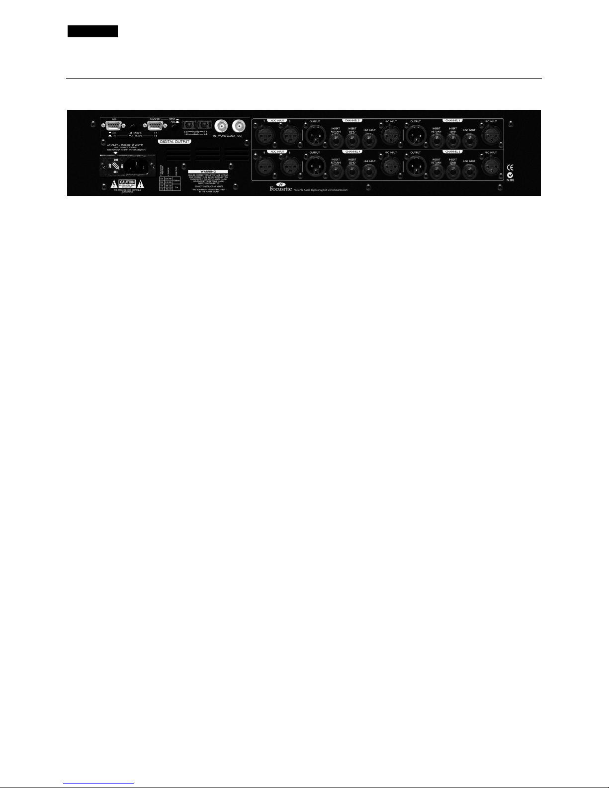
Signal Connections
(Optional ADC shown fitted)
XLR (Audio) Inputs and Outputs
All 3-pin XLR balanced audio connectors (Output, Mic IP
and EXT A/D IP) are wired as follows:
Pin 1 Screen/Chassis
Pin 2 Audio 0°
Pin 3 Audio 180°
Line IP and Insert Sends and Returns
1/4” balanced jack wired as follows:
Tip Audio 0°
Ring Audio 180°
Sleeve Screen/Chassis
Inst. Hi Z IP
1/4” unbalanced jack wired as follows:
Tip Audio 0°
Sleeve Screen/Chassis
Mic IP/Line IP/Inst. Hi Z IP (front panel)
Any one of these inputs may be used as the input to the ISA
428 channels 1-4. Signals routed to these inputs are
referred to as the ‘internal’ channels or signal paths.
Outputs - Channels 1-4
These outputs are used as the main analogue signal outputs,
and are fed by whatever is connected to the Mic Inputs,
Line Inputs, or Instrument Inputs. These outputs also
connect to the ADC ‘internal’ channels 1-4 via the Soft
Limiter circuit.
Insert Send and Return
Allows an external unit, such as a Red 3 Compressor or
Red 2 EQ, to be placed within the signal chain, prior to the
output and post the high pass filter.
ADC Inputs 5-8
The ADC inputs 5-8 act as line level inputs and are used to
route ‘external’ signals to the optional ADC channels 5-8
via the Soft Limiter. Using these inputs in conjunction with a
single optional ADC card, up to eight analogue inputs can
be routed to the eight digital outputs. Using these inputs in
conjunction with a second ISA 428 unit and a single optional
ADC card, eight pre amps can be routed to all eight ADC
channels. (See ‘Signal Connections’ on page 8.)
Retrofitting the Optional ADC
The optional ADC can be retrofitted to a standard ISA 428
at any time. The card can be fitted easily by the user – no
engineering experience is required. Full fitting instructions
for this option are included along with the ADC.
Page 3
ENGLISH
3
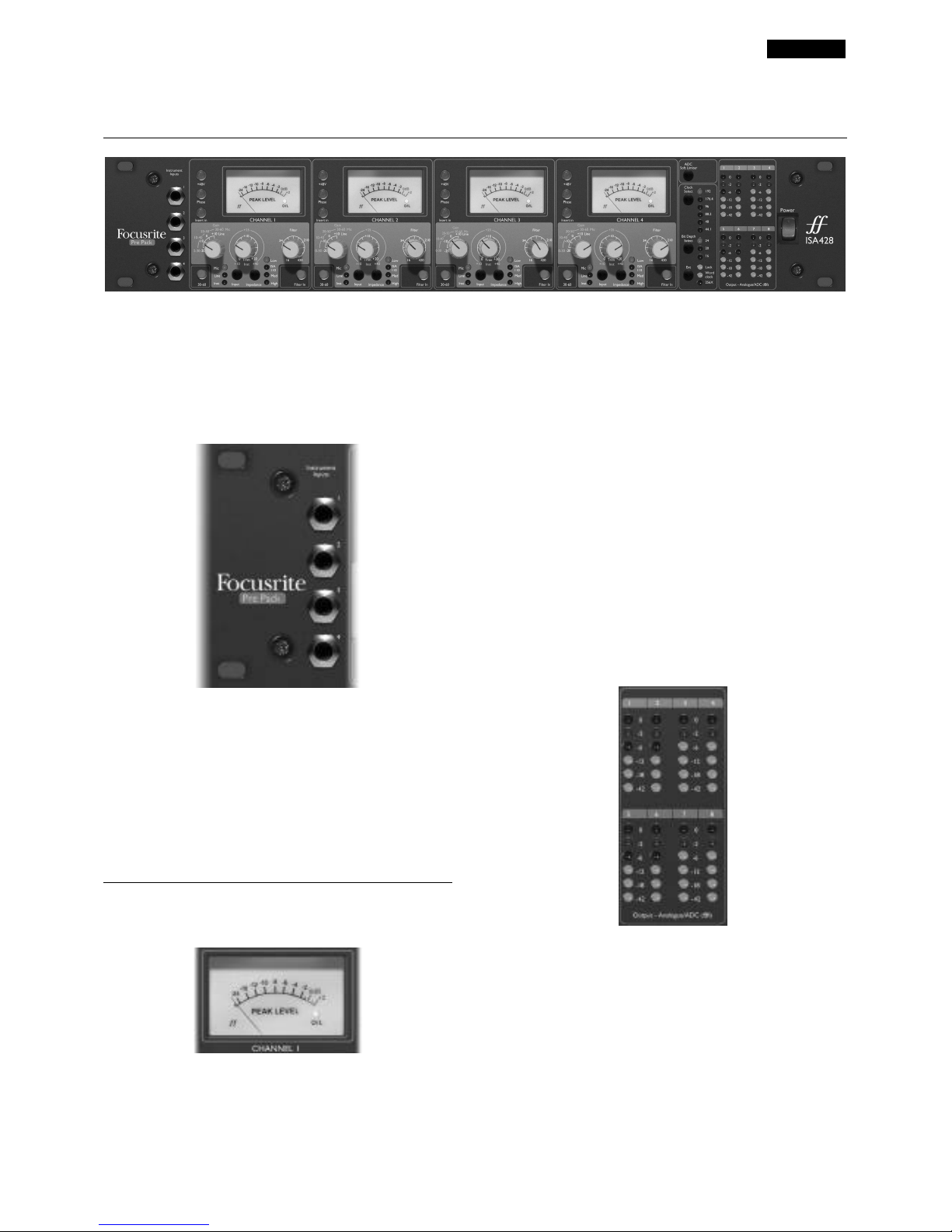
Getting to know the ISA 428
Power
Applies power to the unit. Turn on the ISA 428 before
powering up devices to which the outputs are connected.
Instrument Inputs
Instrument sources may only be connected via the front
panel. Four unbalanced Instrument input connectors are
located to the far left of the front panel and are numbered
1-4, correlating to each of the four channels. These
connectors are used primarily for connecting low level
unbalanced signals such as those from passive guitars and
basses, or from active instruments such as keyboards and
electro-acoustic guitars.
Metering
Peak Meter and O/L LED
This moving coil meter has been designed to have a very
fast reaction time and a slow decay time, and so is perfect
for displaying and holding the peak level of the channel
signal during recording. The meter is fed with a signal taken
from the point in the channel path after the high pass filter
and before the insert send connector. The moving coil peak
meter reading therefore informs the user of the signal level
in the channel after gain has been applied by the pre-amp,
and also shows the level of the signal being sent to any
external equipment connected to the insert send output.
The meter is calibrated relative to the overload point of the
optional ADC card, (0dBfs on the meter refers to the
maximum level that can be converted by the ADC), and
relative to the analogue overload point, (where then 0dBfs
on the meter refers to an analogue level of +22dBu, 6dB
below the maximum analogue level available from the unit).
Within the meter is a hidden overload indicator marked
O/L that lights (red) when the signal in the channel exceeds
0dBfs (+22dBu), and acts as an additional safety feature for
monitoring peak signal levels.
Analogue/ADC dBfs Output meters
These vertical columns of LEDs indicate the peak signal
levels of channels 1-8 in one of two modes, the modes being
defined by the fitting of the optional ADC card as follows:-
Mode 1. Analogue only unit (no optional ADC card
fitted).
Meters 1 to 4 indicate the analogue level at the ISA 428
XLR output connectors for channels 1 to 4. 0dBfs (reached
when the red LED is lit) indicates that a signal level of
+22dbu is present at the output (–18dBfs) therefore
Page 4
ENGLISH
4
indicating that there is a signal level of +4dBu at the output.
Meters 5 to 8 have no function in this mode.
Mode 2. Digital (optional ADC card fitted).
Meters 1 to 8 indicate the signal level that exists in the
signal path after the Soft Limiter and just before the point of
conversion on the optional ADC card. 0dBfs (reached when
the red LED is lit) indicates the maximum signal level that
can be converted by the optional ADC card and should only
be lit for very short durations to ensure a good quality
recording with no digital overload. The meter signal is taken
from a point after the Soft Limiter, so if the Soft Limiter has
been selected to protect the ADC from overload, the effect
of the Soft Limiter on the peak signal levels will be indicated
by a reduction in peak levels on the LED meter.
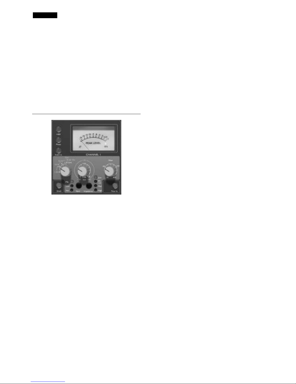
Input Stage
Three input options are provided to give compatibility with
microphone, line or instrument level sources.
Input
Pressing INPUT steps through each of the three inputs, as
indicated by the corresponding LEDs. When the Mic LED is
lit, the microphone input is active etc. Hence a mixture of
microphone, line and instrument inputs may be selected
across the four channels simultaneously.
Mic Input Gain
With the Mic input selected, the user has access to the full
gain range in 10dB steps from 0dB to +60dB (yellow
legend). The gain range is split between two gain modes
depending upon the status of the 30-60 switch.
Mode 1 Mic Gain Range 0-30
With the 30-60 switch off, the rotary gain knob operates
over a gain range of 0dB to +30dB, the level of gain chosen
being indicated on the front panel by the outer arc of yellow
numbers around the gain knob.
Mode 2 Mic Gain Range 30-60
With the 30-60 switch on (illuminated), the rotary gain
knob operates over a gain range of 30dB to 60dB, the level
of gain chosen being indicated on the front panel by the
outer arc of yellow numbers around the gain knob.
An additional 20dB of gain can be applied to the signal after
the Mic/line gain knob using the Trim knob. See ‘Trim’
control text below for full explanation.
Line Input Gain
With the line input selected, the user has access to gain
settings ranging from –20dB to +10dB, indicated on the
front panel by the arc of white numbers around the gain
knob. The 30-60 switch is inactive when the line input is
selected, as the gain range for Line level inputs is restricted
to –20dB to +10dB in 10dB steps.
An additional 20dB of gain can be applied to the signal after
the Mic/line gain knob using the Trim knob. See ‘Trim’
control text below for full explanation.
Instrument Input Gain
With the instrument input selected, gain is applied to the
input signal by using the trim control only, which allows
+10dB to +40dB of gain range. The level of gain chosen is
indicated on the front panel by the outer arc of yellow
numbers around the gain knob. This input is suitable for
high impedance sources such as guitar or bass pickups
(which may be connected directly without the need for an
external DI box) or vintage synthesizers with high
impedance outputs.
Trim
The Trim control provides additional variable gain of 0dB to
+20dB when Mic or line inputs are selected. The level of
gain chosen is indicated on the front panel by the inner arc
of white numbers around the gain knob.
The additional 20dB of gain that can be applied to the Mic
or Line signal is very useful for two reasons:
When high gain is required
The trim used in conjunction with the Mic gain of 60dB will
give a total of up to 80dB of pre-amp gain, making it very
useful for getting good digital recording levels from very low
output dynamic and ribbon microphones.
Gain adjustment during recording
When small amounts of gain adjustment are needed to
correct for performance level variations during recording,
use the trim knob rather than the stepped Mic/Line gain
knob, as switching the 10dB gain steps would be much too
intrusive. It is therefore good practice to apply some Trim
gain before using the 10dB stepped gain knob to find the
optimum recording level so that the Trim control can be
used to gently add or take away gain later, if so required.
+48V
Pressing the +48V switch provides +48V phantom power,
suitable for condenser microphones, to the rear panel XLR
microphone connector. This switch does not affect the
other inputs. If you are unsure whether your microphone
requires phantom power, refer to its handbook, as it is
possible to damage some microphones (most notably
Ribbon Microphones) by providing phantom power.
Page 5
ENGLISH
5
Phase
Pressing PHASE inverts the phase of the selected input, to
correct phase problems when using multiple microphones,
or when incorrect wiring polarity has occurred.
Insert In
Pressing the INSERT switch (illuminated) breaks the signal
path of the channel, so that the channel input signal is sent
out of the unit from the rear panel Insert Send connector
and returned to the same point in the signal chain via the
rear panel Insert Return connector.
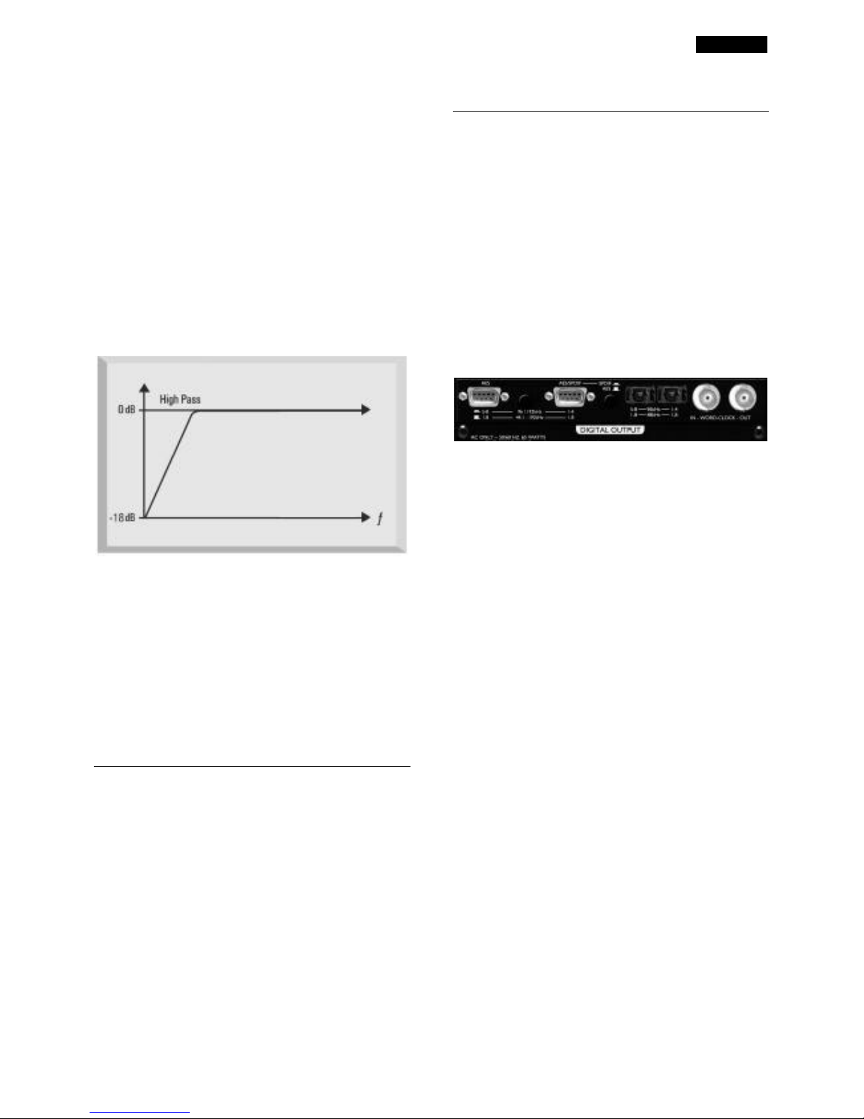
Filter In
Pressing the FILTER IN switch makes the Hi Pass Filters
active in the audio path. The filter provides 18dB/octave
roll-off. A variable control allows the roll-off frequency to
be set within the range of 16Hz to 420Hz.
Impedance
Pressing IMPEDANCE steps through each of the four
transformer pre-amp input impedance values, as indicated
by the corresponding LEDs. By selecting different values for
the impedance of the ISA 428 transformer input, the
performance of both the ISA 428 pre-amp and the
microphone connected can be tailored to set the desired
level and frequency response.
Analogue to Digital converter (ADC)
Soft Limiter
Pressing ADC SOFT LIMITER activates the ADC Soft
Limiter - giving total protection of all 8 channels on the
ADC.
ADC Soft Limiter Operation
The Soft Limiter circuit acts instantaneously, clamping down
the audio so that the signal can never go above the
maximum level that the ADC can accurately convert
(0dBfs). Consequently, it is impossible to overload the
connected optional ADC card. This function is a part of the
ADC signal path, and so only operates when an ADC card
is fitted. If no card is fitted then the switch is inactive.
8 Channel Digital Output Option
The ISA 428 can be used as a high quality 8 channel ADC
for analogue transfer to digital with the addition of the
optional ISA 428 digital output board. The 4 external ADC
inputs and the main channel inputs can all be fed to the
ADC, via the Soft Limiter, ensuring eight super-clean,
protected, high-quality paths to digital. A single ISA 428 unit
can act as an 8-channel digital input expansion unit to any
DAW. Channels 1-4 always route respectively to ADC
output channels 1-4.
Alternatively, two ISA 428 units with a single A/D option
can be used to create an 8-channel mic pre to A/D system
(see ‘Signal Connections’ on page 8). Digital formats
available on the ADC are AES/EBU, SPDIF and ADAT™
optical format (the ADAT™ outputs can also operate in
high speed SMUX mode for 96kHz transfer speeds, but are
muted during 192kHz operation).
24-bit/96kHz ADAT™ interface operation
The card provides digital outputs for all eight ISA 428
channels, which operate over the sample frequency ranges
44.1, 48, 88.2 and 96kHz, and can be dithered to 16-, 20-,
or 24-bit depths depending upon the destination.
The card features two ADAT™-type ‘lightpipe’ output
connectors. For speeds up to 48kHz both connectors
transmit all 8 channels simultaneously. However, ADAT™type connectors are bandwidth-limited at sample rates
above 48kHz - each audio channel uses two ADAT™ digital
channels to accommodate the increased quantity of data,
hence the need for two ADAT™ connectors to allow 8
channels of conversion at high speed.
The ADAT™ output connectors operate as follows:
44.1/48Khz sample rates:
Connector 1 = channels 1 to 8 in parallel.
Connector 2 = channels 1 to 8 in parallel (identical to
connector 1)
88.2/96Khz sample rates:
Connector 1 = channels 1 to 4.
Connector 2 = channels 5 to 8.
ADAT™ lightpipe cables are available from your local
dealer, or in the UK from Studiospares (tel +44 (0)20 7482
1692): stock number 585-510.
24-bit/192kHz AES/SPDIF operation
The card also provides AES and SPDIF format outputs via
two 9-pin D-type connector on the rear panel. The full
range of sample rates (up to 192kHz) and bit depths are
available.
Page 6

ENGLISH
6
To access the digital signals from the 9-pin D-type output
connectors, the A/D card must be purchased with either an
AES or SPDIF D-Type conversion cable as follows:
AES cable: 9-pin D-type to 4 male XLR connectors.
SPDIF cable: 9-pin D-type to 4 male RCA (phono)
connectors.
Note: cables need to be purchased separately. Since there
are two different cable options - XLR for AES and
RCA/phono for SPDIF - these are not included with the
A/D converter options. Focusrite cables may be purchased
from your local dealer. If you experience difficulty in
obtaining these cables, contact your local distributor as
listed in the back of this manual.
The AES/SPDIF Connector Configuration
There are two AES connectors which can be configured as
follows:
AES/SPDIF 9-pin D-type
The connector labelled AES/SPDIF can be configured either
as an AES or an SPDIF dedicated output using the
AES/SPDIF switch next to it. When operating the connector
in AES mode an AES cable is required. When operating in
SPDIF mode the SPDIF RCA cable should be used, which
automatically sets the output stream to consumer mode.
AES 9-pin D-type
The second AES connector labelled AES always transmits in
AES-only mode regardless of the position of the AES/SPDIF
switch. The switch between the two 9-pin D-type
connectors selects the AES output between ‘1 wire’ and ‘2
wire’ mode as follows:
1 Wire Mode
Selected with the switch in the ‘out’ position. Both AES
connectors transmit 8 channels of AES data simultaneously
for all sample frequencies from 44.1 to 192kHz.
2 Wire mode
Selected with the switch in the ‘in’ position. Each AES
connector transmits 4 channels of AES data separately for
sample frequencies from 96kHz to 192kHz.
The reason for the two modes is that older equipment with
96kHz and 192kHz AES inputs can only receive speeds up
to 192kHz by using both digital channels of a single AES
connection (known as ‘2 wire’). Therefore one AES channel
can only send a single channel of digital data, and thus the 9pin D-type is switched from transmitting 8 channels of data
to sending 4 channels of data. Therefore to send all 8
channels from the ISA 428 in this mode requires two AES
connectors: one sending channels 1 to 4 (AES/SPDIF
connector) and the other sending channels 5 to 8 (AES-only
connector). Having this switch makes the ISA 428 useable
with both old and new equipment.
Word Clock In and Out
The internal ADC can be synchronised to an external word
clock. By pressing the front panel Ext switch, the
synchronisation mode can be switched between standard
external word clock and 256X external word clock. Both
types of external word clock should be connected to the
ISA 428 ADC card at the Word Clock In BNC connector.
The Word Clock Out BNC connector either regenerates
the external word clock connected at the Word Clock In
BNC connector, or transmits the internal sample frequency
of the ADC card. Where the ISA 428 is being used as a
slave device within a larger digital system, the Word Clock
Out BNC connector can be used to pass on the external
word clock signal to the next device. When the unit is not
slaved to another device and is in internal clock mode, the
Word Clock Out BNC connector outputs the sample
frequency selected on the ISA 428 front panel.
Digital Output Front Panel Controls
Clock Select
Pressing this switch allows the user to select between
sample frequencies of 44.1kHz, 48kHz, 88.2kHz, 96kHz,
176.4kHz, and 192kHz
Bit Depth Select
Selectable between 24, 20 and 16 bits.
Ext Select
Pressing EXT allows the ISA 428 to be slaved to an external
word clock source. Selecting 256X allows the ISA 428 to be
slaved to an external clock running at 256 times faster than
the sample frequency and enables connection to systems
such as the Digidesign 'Superclock' or other 256 slave clock
devices.
Lock LED
When lit, LOCK indicates that the unit is synchronised to
an external clock.
Page 7

ENGLISH
7
Applications
Mic Pre-amp Input Impedance
A major element of the sound of a mic pre is related to the
interaction between the specific microphone being used and
the type of mic pre-amp interface technology it is connected
to. The main area in which this interaction has an effect is
the level and frequency response of the microphone, as
follows:
• Level
Professional microphones tend to have low output
impedances and so more level can be achieved by
selecting the higher impedance positions of the ISA 428
mic pre-amp.
• Frequency response
Microphones with defined presence peaks and tailored
frequency responses can be further enhanced by
choosing lower impedance settings. Choosing higher
input impedance values will tend to emphasise the high
frequency response of the microphone connected,
allowing you to get improved ambient information and
high end clarity, even from average-performance
microphones.
Various microphone/ISA 428 pre-amp impedance
combinations can be tried to achieve the desired amount of
colouration for the instrument or voice being recorded.
To understand how to use the impedance selection
creatively it may be useful to read the following section on
how the microphone output impedance and the mic preamp input impedance interact.
Switchable Impedance: In Depth
Explanation
Dynamic moving coil and condenser microphones
Almost all professional dynamic and condenser
microphones are designed to have a relatively low nominal
output impedance of between 150Ω and 300Ω when
measured at 1kHz. Microphones are designed to have such
low output impedance because the following advantages
result:
• They are less susceptible to noise pickup.
• They can drive long cables without high frequency roll-
off due to cable capacitance.
The side-effect of having such low output impedance is that
the mic pre-amp input impedance has a major effect on the
output level of the microphone. Low pre-amp impedance
loads down the microphone output voltage, and emphasises
any frequency-related variation in microphone output
impedance. Matching the mic pre-amp resistance to the
microphone output impedance, (e.g. making a pre-amp input
impedance 200Ω to match a 200Ω microphone) still
reduces the microphone output and signal to noise ratio by
6dB, which is undesirable.
To minimise microphone loading, and to maximise signal to
noise ratio, pre-amps have traditionally been designed to
have an input impedance about ten times greater than the
average microphone, around 1.2kΩ to 2kΩ. (The original
ISA 110 pre-amp design followed this convention and has an
input impedance of 1.4kΩ at 1kHz.)
Input impedance settings greater than 2kΩ tend to make
the frequency-related variations of microphone output less
significant than at low impedance settings. Therefore high
input impedance settings yield a microphone performance
that is more flat in the low and mid frequency areas and
boosted in the high frequency area when compared to low
impedance settings.
Ribbon microphones
The impedance of a ribbon microphone is worthy of special
mention, as this type of microphone is affected enormously
by pre-amp impedance. The ribbon impedance within this
type of microphone is incredibly low, around 0.2Ω, and
requires an output transformer to convert the extremely
low voltage it can generate into a signal capable of being
amplified by a pre-amp. The ribbon microphone output
transformer requires a ratio of around 1:30 (primary:
secondary) to increase the ribbon voltage to a useful level,
and this transformer ratio also has the effect of increasing
the output impedance of the mic to around 200Ω at 1kHz.
This transformer impedance, however, is very dependent
upon frequency - it can almost double at some frequencies
(known as the resonance point) and tends to roll off to very
small values at low and high frequencies. Therefore, as with
the dynamic and condenser microphones, the mic pre-amp
input impedance has a massive effect on the signal levels and
frequency response of the ribbon microphone output
transformer, and thus the ‘sound quality’ of the
microphone. It is recommended that a mic pre-amp
connected to ribbon microphone should have an input
impedance of at least 5 times the nominal microphone
impedance.
For a ribbon microphone impedance of 30Ω to 120Ω the
input impedance of 600Ω (Low) will work fine and for 120Ω
to 200Ω ribbon microphones the input impedance setting of
1.4kΩ (ISA 110) is recommended.
Impedance Setting Quick Guide
In general the following selections will yield the following
results:
High mic pre-amp impedance settings
• Will generate more overall level
• Will tend to make low- and mid-frequency response of
the microphone flatter
• Will improve high-frequency response of the
microphone.
Low pre-amp impedance settings
• Will reduce the microphone output level
• Will tend to emphasise the low- and mid-frequency
presence peaks and resonant points of the microphone
Page 8

ENGLISH
8
Signal Connections
Page 9

ENGLISH
9
Using the ISA 428 with a Digidesign 192
HD™ interface
The ISA 428 can be used with the Digidesign 192 HD™
interface in one of two ways as follows:
Analogue mode
The XLR analogue outputs of the ISA 428 can be connected
to the +4dBu balanced 25-way DB25 connector, labelled
‘Analog Input’, of the HD interface using a DB25 to 8 off
female XLR cable. These cables are available directly from
Digidesign or from Hosa cable (part no. DTF 805).
N.B. Digidesign cables are also available as follows:
Description Part no
DB25-XLR M+F AES/EBU Snake, 12' MH080
DB25-XLRM Snake, 12' MH081
DB25-XLRF Snake, 12' MH082
DB25-TRS Snake, 12' MH083
DB25-XLR M+F AES/EBU Snake, 4' MH097
DB25-XLRM Snake, 4' MH098
DB25-XLRF Snake, 4' MH099
DB25-TRS Snake, 4' MH100
The ISA 428 ADC level meters are calibrated to show 0dBfs
at +22dBu and the HD interface unit can be calibrated such
that it too indicates 0dBfs at +22dBu which will make
interfacing and level checking between the two units easier.
To recalibrate the HD unit follow the instruction described
in the Digidesign 192 HD™ user guide under ‘192 I/O
Calibration Mode Instructions’.
Digital Mode
Connecting the ISA 428 AES digital output 9-way connector
to the HD unit 25-way ‘AES/EBU I/O’ connector requires
two cables. The Focusrite ISA 428 9-way cable to 4 off XLR
is required to retrieve the AES signals from the ISA 428
ADC card, and this should be connected to the AES input
connectors on the Digidesign 25-way to AES I/O XLR cable.
This cable is available directly from Digidesign and is called a
‘DB25-XLR M+F AES/EBU DigiSnake™’.
Note on HD AES channel restriction
The AES/EBU DB25 way connector on the rear of the HD
unit can accept 8 channels of AES/EBU digital data over four
AES cables for speeds up to 96kHz. However, for speeds
over 96kHz (up to 192kHz) the four AES inputs of the HD
interface can only accept 4 channels of audio data.
When the ISA 428 is operating at speeds up to 96kHz a
single Focusrite 9-way to AES XLR cable can route all 8
channels of its digital audio into the HD interface. When the
ISA 428 is operating at 176.4 to 192kHz a single Focusrite
9-way to AES XLR cable can only route 4 channels of its
digital audio into the HD interface. Depending upon which
9-way connector the Focusrite cable is attached to on the
ADC card, either channels 1 to 4 or 5 to 8 can be routed
into the HD unit.
Page 10

ENGLISH
10
Other Compatible Focusrite Products
Red 2
A dual equaliser which features Focusrite’s much soughtafter warmth and smoothness. Features include 4 band EQ HF and LF shelving, true parametric High- and Low- Mids,
and High-pass and Low-pass filters.
Red 3
A Class A VCA-based dual mono/stereo compressor/
limiter. The compressor/limiter features a single Class A
VCA to achieve truly high class compression and limiting
free of the usual compromises.
Red 7
A powerful and versatile direct recording processor,
featuring a compressor, de-esser and exciter. It features a
single Red Range mic pre, plus a mono channel of the
dynamics from the Red 3, with the addition of a deesser/exciter.
ISA 430 Producer Pack,
The only Focusrite product to include a wide range of
different classic Focusrite modules in a single frame. In
addition to retaining the classic look and sound of the
original ISA 110 EQ and some of the original ISA 130
dynamics, it adds new processing technology, state-of-theart routing flexibility, and digital connectivity.
ISA 220 Session Pack
The ISA 220 Session Pack provides all the legendary audio
processing tools required to infuse your session with
Focusrite's renowned sonic performance. It features many
of the original circuits of the flagship ISA 430 Producer Pack
along with some new features of its own.
Platinum Compounder
A high performance dual-channel dynamics processor
designed for the quality conscious professional and project
studio owner. The combination of high quality compression
with the powerful Bass Expander makes this unit a must
have for any dance music engineer or musician.
Platinum MixMaster
An analogue stereo audio processor designed primarily for
project studio mastering. However, with so many useful
features in one box, anyone involved in the business of
making music will quickly find it indispensable at other
stages of the recording process too.
Platinum Penta
Every dynamics processor you'll ever need, squeezed into
one 2U rack-mountable unit, the Penta features a Focusrite
Class A pre-amp on the front end with both mic and
instrument inputs accessible directly from the front fascia.
Following this is a Stereo Preset Compressor, which is
entirely editable and features Focusrite’s exclusive Tube
Sound Technology.
Platinum Trak Master
Never before has there been a more affordable tracking
device, which still manages to encompass the design
philosophy and integrity that have ensured that Focusrite be
held in such high esteem over so many years. A high quality
mic pre, intuitive compression, a three band flexible EQ, and
'tube sound' control come together in this unit to ensure
you have all you require to get a quality signal tracked.
Platinum VoiceMaster Pro.
VoiceMaster Pro represents a new generation of voice
recording equipment. The award-winning Class A preamp
captures every nuance from any source, whilst latency-free
monitoring ensures direct and delay-free mix control. Tools
such as the voice-optimised EQ, Vintage Harmonics and
Tube Sound allow you to get creative with a touch of class,
putting your own stamp on every recording.
Check out www.focusrite.com for further information on
any of these products and for any future products which
may be compatible with the ISA 428.
Page 11

ENGLISH
11
FAQs
Q: What are the basic features of the ISA 428?
A: Four Focusrite mic pre's, eight line inputs, four
instrument inputs, optional 8-channel 192kHz A/D
conversion.
Q: Which applications is the ISA 428 suitable for?
A: The ISA 428 can be used as a multi-channel high quality
front end for Digital Audio Workstations, allowing multichannel recording to HD. Equally it can be used simply as
the perfect interface/ A/D converter for synths/other line
level devices. It also provides additional channels for anyone
who has run out of mic pre’s on their analogue console
(either live or recording,) and is especially useful as a source
of additional mic pre’s for digital consoles.
Q; Which Focusrite pre is featured on the ISA 428?
A: It's the original transformer-balanced mic pre that
featured in the classic analogue Focusrite consoles in the
1980s. This is also the classic pre that features in the ISA
430 Producer Pack.
Q: Do the pre's have the usual phantom power and
High Pass Filter controls?
A: Yes, and more… each pre has switchable mic impedance
so that you can match to your chosen mic's impedance, or
'mismatch' for creative 'input response colours'. Also there
are inserts per channel, plus sweepable HPF, phase reverse,
and phantom power.
Q: What's significant about the impedance
switching for each pre?
A: Each pre can either be matched perfectly to any
microphone, (vintage or modern,) or offset to offer a
variety of 'response colours' by interacting with any
particular microphone. The impedance of each pre amp is
switchable (via a single switch labelled 'Impedance') between
4 settings: original ISA 110 (Zobal network influence for the
classic Vintage Focusrite sound,) Low (600 Ohms, tends
towards flat and tight sounding,) High (2.4k, relatively open,)
and Higher (6.8K, relatively lively, great for room
ambience.)
Q: Are insert points featured?
A: Yes, switchable in- or out- of circuit on each of channels
1-4.
Q: What are the four extra inputs on the left hand
side of the front fascia for?
A: They are unbalanced inputs which enable you to easily
connect unbalanced sources like guitars/basses to the unit
without the need for an external DI box.
Q: Why are there eight line inputs but only 4 mic
pre's?
A: For two reasons. Firstly it means you can route 8 line
level sources to the 8-channel 192k converter with a single
unit. Secondly, you can convert the 4 pre system to an 8pre system with 2 units, see below.
Q: Why is it called "428"?
A: Because it's easy to convert a 4-pre-to-digital system to
an 8-pre-to-digital system.
Q; Can I use 2x ISA 428s with 1x A/D card? If so,
how does the routing work?
A: Yes. Mic pre's 1 to 4 on the first unit route directly (via
the limiter) to digital outputs 1, 2, 3, 4. Mic pre's 5 to 8 on
the second unit then route out of their respective analogue
outputs, and loop back in to the line inputs 5, 6, 7, 8 on the
first unit. These then route directly (via the limiter) to
digital outputs 5-8.
Q: But if I run an 8-channel system how can I
monitor levels?
A: Easy. Each 428 includes 8 output meters, as well as 4
channel peak-reading input meters.
Q: What's the specification of the A/D option?
A: AES, (both single and dual wire specs.) SPDIF, ADAT™
formats, sample rates selectable between 44.1, 48, 88.2, 96,
176.4 and 192kHz, (ADAT is max 96kHz of course, via 2
ports,) 16, 20, and 24 bit with adaptive dithering, internal or
external word clock, and 256X clock, S/N Ratio better than
120dBfs ‘A-weighted’. Connections are via 2 x 9-pin D-type
connectors and standard lightpipes, word clock is via BNC
in and out.
Q: Does the ISA 428’s A/D option feature word
clock as standard?
A: Yes, word clock may be fed in via a BNC connector on
each A/D to allow syncronisation to any word clock master
source.
Q: Why do I need word clock anyway?
A: When using multiple pieces of digital equipment it is
necessary to make sure that their bit-streams are all in sync.
In order to do this all equipment need to be synchronised
to a common word clock system. Somewhere in this system
a word clock ‘master’ must be dictating the word clock for
the rest of the equipment (‘word clock slaves’) to follow.
Failure to sync all pieces of digital equipment to a common
word clock source will result in audible clicks and glitches in
programme material. Note that the 428 regenerates word
clock at its BNC output, further boosting word clock
stability.
Q: What if my system only operates at 16 bit,
44.1kHz?
A: No problem, the ISA 428 features adaptive dithering and
supports most sample rates, (simply select the rate you
need from the ISA 428’s front panel,) so you can use an ISA
428 with a 16, 20 or 24 bit system operating at 44.1, 48,
88.2, 96, 176.4 or 192kHz.
Q: How many rack spaces does ISA 428 take up?
A: The ISA 428 is a 2U device.
Q: What rear panel connections are featured?
A: The ISA 428 has 4 XLRs for microphone input, and 8
XLR line level inputs. There are 4 balanced XLR analogue
outputs, plus separate balanced quarter inch send and
return insert sockets per channel. Plus digital connections if
the optional A/D is fitted of course, see above. Finally
there's a voltage-switching power socket to connect to the
internal power supply.
Page 12

ENGLISH
12
Q: Is the ISA 428 a Class A device, and why is that
important?
A: Yes, the ISA 428 is a Class A device. Why? Class A is a
type of amplifier design in which you have a standing DC
current running through your amplifier circuits all the time.
As the signal comes along you vary what you're taking from
that, rather than switching between supplying a positive
current for one half of the waveform and a negative current
for the other half. This results in the ability to represent
audio in a more linear (distortion free) manner all the way
through the circuit. Cheaper processors use IC amplifiers
which run close to Class B and don't have the same standing
DC current, which means the transistors inside the chips
switching off and on, inevitably resulting in a less linear
performance.
Q: Should balanced connectors be used with the ISA
428?
A: Yes, where possible. Alternatively, if using an unbalanced
instrument source, you can connect to the four unbalanced
1/4" inputs.
Q: What's the ISA 428's bandwidth? Does it have
the same kind of spectacular bandwidth that has
given the Red and ISA range units their reputation
for ‘open-ended’ sound?
A: Yes. The bandwidth is the same as the classic Focusrite
units of old: 10Hz-200kHz!
Q: Is there an optional digital input card?
A: No, because the ISA 428 is primarily a 'front end'
product. In other words, the only devices which are likely
to be connected to the 428's inputs are analogue sound
sources such as microphones, guitars etc.
Q: Why is the 24-bit 192kHz specification
important?
A: An A/D converter works by sampling the audio
waveform at regular points in time, and then quantizing
those values into a binary number, which relates to the
number of bits specified. The quantized signal must then be
passed through a D/A converter before it becomes audible.
In simple terms, the D/A essentially joins the dots plotted
by the A/D converter when the signal was first converted to
digital. The number of dots to join, combined with how
little those dots have been moved, determines how
accurate the final signal will be compared to the original.
The greater the sample rate and bit rate, the more accurate
the whole digital process is. So 24 bit/192kHz performance
will ensure more accurate digital transfer of your audio
information compared to the old 16-bit/44.1kHz standards.
This is especially important if further digital signal processing
is to be applied to the signal once converted to digital, as
any mathematical operations taking place on the data, (for
example as a result of a gain change, or dynamic effect
process,) may result in quantization and rounding errors.
The higher the resolution of the digital data, the smaller the
audible effect of these errors.
Q: What is dithering? Why do I need it?
A: When dropping down from e.g. 24 bit to 16 bit,
quantizing errors occur, (because 24 bit sampling involves
more samples than 16 bit, so when you reduce the bit
depth the extra samples have ‘nowhere to go.’) At high
signal levels these errors are random and not audible, but at
lower signal levels the errors correlate more closely to the
audio and become audible as distortion. Dithering effectively
‘randomises’ the truncation errors at lower levels, causing
the 'least significant bit' distortion to disappear.
Q: Can I retrofit a digital board to an analogue ISA
428 at a later date?
A: Yes, and you can do it yourself - it can easily be retrofitted at any time without any soldering etc, just a few
screws to undo, and one clip-connector to join to the main
PCB.
Q: How can the ISA 428 operate with the ADAT
lightpipe format at 96kHz? I thought the maximum
sample rate for this format was 48kHz?
A: Not any more. The ISA 428 supports the new 96kHz
ADAT specification, using two discrete optical ports.
Q: How many digital outputs can I use at the same
time?
A: It depends on which sample rate you choose.
At 48kHz or lower: 8 AES + 8 S/PDIF (or 2 x 8 AES) + 2 x
8 ADAT = max. 32 outputs simultaneously.
At 96kHz: 8 AES* + 8 S/PDIF (or 2 x 8 AES) + 8 ADAT =
max. 24 outputs simultaneously.
At 192kHz: 8 AES* + 8 S/PDIF (or 2 x 8 AES,) no ADAT**
= max. 16 outputs simultaneously.
* NB Both AES single-wire and split-wire configurations are
supported; split wire will obviously reduce the maximum
number of simultaneous outputs.
**At 192kHz: the ADAT ports are muted.
The digital outputs can always be fed with any mix of mic,
line, inst. inputs.
Q: When the A/D is used, are my analogue outputs
available for use?
A: Yes. The 4 line outputs can run simultaneously with all of
the ADAT, AES and S/PDIF outputs.
Q: Do I need to buy an option cable to use either of
the A/D cards?
A: Yes; ADAT optical cables are available from many
sources, and Focusrite offer their own 8-channel 9-pin to 4
phono (RCA) connectors S/PDIF cable and 9-pin to 4 XLR
connectors AES-EBU cable.
Page 13

ENGLISH
13
Specifications
Mic Input Response
• Gain range = 0dB to 60dB in 10dB steps.
• Input Impedance, variable as follows:-
Switched Impedance
setting
Equivalent Input Impedance at
1KHz
Low 600Ω
ISA110 1400Ω
Med (Medium) 2400Ω
High 6800Ω
• EIN (equivalent input noise) = -128dB measured at
60dB of gain with 150 Ohm terminating impedance and
20Hz/22kHz bandpass filter.
• Noise at main output with gain at unity (0dB) = -97dBu
measured with a 20Hz/22kHz bandpass filter.
• Signal to noise ratio relative to max headroom (28dBu)
= 125dB
• Signal to noise ratio relative to 0dBfs (+22dBu) = 119dB
• THD at medium gain (30dB) = 0.001% measured with a
1KHz -20dBu input signal and with a 20Hz/22kHz
bandpass filter.
• Frequency response at minimum gain (0dB) = -0.25dB
down at 20Hz and –3dB down at 120kHz.
• Frequency response at maximum gain (60dB) = –2.5dB
down at 20Hz and –3dB down 120kHz.
• CMRR at full gain (60dB) = 80dB. (check 220 figure)
Line Input Response
• Gain range = -20dB to +10dB in 10dB steps.
• Input Impedance = 10kΩ from 10Hz to 200kHz.
• Noise at main output with gain at unity (0dB) = -91dBu
measured with a 20Hz/22kHz bandpass filter.
• Signal to noise ratio relative to max headroom (28dBu)
= 119dB
• Signal to noise ratio relative to 0dBfs (+22dBu) = 113dB
• THD at unity gain (0dB) = .002% measured with +4dBu
input signal and with a 20Hz/22kHz bandpass filter.
• Frequency Response at unity gain (0dB) = 0.25dB down
at 20Hz and –3dB down at 140kHz.
Instrument Input Response
• Gain range = 10dB to 40dB continuously variable
• Input Impedance = >1Meg Ohm.
• Noise at minimum gain (0dB) = -90dBu measured with
a 20Hz/22kHz bandpass filter.
• Noise at maximum gain (40dB) = -78dBu measured
with a 20Hz/22kHz bandpass filter.
• THD at minimum gain (0dB) = .006% measured with
–10dBu input signal and with a 20Hz/22kHz bandpass
filter.
• Frequency Response at 10dB gain = 0.2dB down at
26Hz and 0dB at 32kHz.
• Frequency Response at 40dB gain = -3dB down at 26Hz
and –3dB down at 32kHz.
High Pass Filter
• Roll off = 18dB per octave 3 pole filter
• Frequency Range = continuously variable from 16Hz to
420Hz measured at the 3dB down point.
Input Meter
• Calibrated for 0dBfs = +22dBu and indicates the level
after the High Pass Filter and before the Insert Send
output.
• O/L LED = is lit when signal level reaches a level
greater than 0dBfs.
Soft Limiter
• Threshold = -6dBfs (+16dBu)
• Limiter ratio is level dependent as follows:-
Signal Level Input to Output Level Reduction Ratio
-6dBfs to –4dBfs Infinite:1
-4dBfs to 0dBfs 2:1
0dBfs to +6dBfs 1.5:1
• Attack time = instant
• Release time = instant
• Noise = -95dBu measured with a 20Hz/22kHz bandpass
filter.
ADC Meter
• 6 LED meter is calibrated relative to 0dBfs where 0dBfs
= +22dBu (the maximum level which can be correctly
converted by the optional internal A/D converter
before overload occurs). The meter calibration points
are as follows:
Meter panel calibration
value in dBfs
Equivalent dBu value
0dBfs +22dBu (the maximum level
into the converter)
-2dBfs +20dBu
-6dBfs +16dBu
-12dBfs +10dBu
-18dBfs +4dBu
(the average level to allow
20dB of headroom for EQ and
dynamics processing).
-42dBfs -20dBu
Page 14

ENGLISH
14
Warranty
All Focusrite products are covered by a warranty against
manufacturing defects in material or craftsmanship for a
period of one year from the date of purchase. Focusrite in
the UK, or its authorised distributors worldwide, will do
their best to ensure that any fault is remedied as quickly as
possible. This warranty is in addition to your statutory
rights.
This warranty does not cover any of the following:
• Carriage to and from the dealer or factory for
inspection or repair.
• Labour charge if repaired other than by the distributor
in the country of purchase or Focusrite in the UK.
• Consequential loss or damage, direct or indirect, of any
kind, however caused.
• Any damage or faults caused by abuse, negligence,
improper operation, storage or maintenance.
If a product is faulty, please first contact the dealer from
which the product was purchased. If the product is to be
shipped back, please ensure that it is packed correctly,
preferably in the original packing materials. We will do our
best to remedy the fault as quickly as possible.
Please help us to serve you better by completing and
returning the Warranty Registration Card, or registering
online at http://www.focusrite.com. Thank you.
Accuracy
Whilst every effort has been made to ensure the accuracy
and content of this manual, Focusrite Audio Engineering Ltd
makes no representations or warranties regarding the
contents.
Copyright
© 2002-2003 Focusrite Audio Engineering Ltd. All rights
reserved. No part of this manual may be reproduced,
photocopied, stored on a retrieval system, transmitted or
passed to a third party by any means or in any form without
the express prior consent of Focusrite Audio Engineering
Ltd.
ADAT™ is a registered trade mark of Alesis Corporation
Inc.
192 HD™ is a registered trade mark of Digidesign Inc.
 Loading...