

Page 1
ENGLISH
1
Introduction
Thank you for purchasing the ISA 220 Session Pack brought
to you by the Focusrite team – Trevor, Peter, Martin,
Helen, Raf, Tom, Mick, Phil, Chris, Micky, Pauline, Jo, Chris,
Bryn, Giles, Rob and Simon.
The chaps at Focusrite are a jolly hard working bunch and
take a great deal of pride in designing, building and delivering
the best audio units around. We hope your new Focusrite
unit lives up to that reputation, and that you enjoy many
years of productive recording.
If you would like to tell us about your recording
experiences then please email us at: sales@focusrite.com
The Focusrite Team
Contents
Introduction..............................................................................................1
Contents.....................................................................................................1
Important Safety Instructions.............................................................1
Power Connections...............................................................................1
Signal Connections.................................................................................2
Getting to know the ISA 220.............................................................3
Metering.....................................................................................................3
Input Stage.................................................................................................4
EQ Module................................................................................................4
Compressor..............................................................................................6
De-esser.....................................................................................................7
Limiter.........................................................................................................8
Output.........................................................................................................8
Stereo A/D................................................................................................8
Applications...............................................................................................9
FAQs.........................................................................................................11
Specifications.........................................................................................13
Warranty.................................................................................................14
Accuracy..................................................................................................14
Copyright................................................................................................14
Focusrite Distributors.......................................................................71
Reset Sheet
.............................................................................................72
Important Safety Instructions
Please read all of these instructions and save them for
future reference. Follow all warnings and instructions
marked on the unit.
• Do not obstruct air vents in the rear panel. Do not
insert objects through any apertures.
• Do not use a damaged or frayed power cord.
• Unplug the unit before cleaning. Clean with a damp
cloth only. Do not spill liquid on the unit.
• Unplug the unit and refer servicing to qualified service
personnel under the following conditions:
If the power cord or plug is damaged; if liquid has
entered the unit; if the unit has been dropped or the
case damaged; if the unit does not operate normally or
exhibits a distinct change in performance. Adjust only
those controls that are covered by the operating
instructions.
• Do not defeat the safety purpose of the polarised or
grounding-type plug. A polarised plug has two blades
with one wider than the other. A grounding type plug
has two blades and a third grounding prong. The wider
blade or the third prong are provided for your safety.
When the plug provided does not fit into your outlet,
consult an electrician for replacement of the obsolete
outlet.
WARNING:
THIS UNIT MUST BE EARTHED BY THE POWER
CORD.
UNDER NO CIRCUMSTANCES SHOULD THE
MAINS EARTH BE DISCONNECTED FROM THE
MAINS LEAD
This unit is capable of operating over a range of mains
voltages as marked on the rear panel. Ensure correct mains
voltage setting and correct fuse before connecting mains
supply. Do not change mains voltage settings while mains
supply is connected. To avoid the risk of fire, replace the
mains fuse only with the correct value fuse, as marked on
the rear panel.
The internal power supply unit contains no user serviceable
parts. Refer all servicing to a qualified service engineer,
through the appropriate Focusrite dealer.
Power Connections
There is an IEC mains lead supplied with the unit, which
should have the correct moulded plug for your country.
The wiring colour code used is:
For units shipped to the USA, Canada, Taiwan and Japan:
Live - Black Neutral - White Earth - Green
For units shipped to any other country:
Live - Brown Neutral - Blue Earth - Green and Yellow
Page 2

ENGLISH
2
Signal Connections
(Optional A/D Card shown fitted)
XLR (Audio) Inputs and Outputs
All 3-pin XLR audio connectors (Output, Mic IP, Line IP,
and EXT A/D IP) are wired as follows:
Pin 1 Screen/Chassis
Pin 2 Audio 0°
Pin 3 Audio 180°
Inst. Hi Z IP, Comp Key IP, Int A/D Direct
Input and Dynamic Link
1/4” jack wired as follows:
Tip Audio 0°
Ring Audio 180°
Sleeve Screen/Chassis
Mic IP/Line IP/Inst. Hi Z IP
Any one of these inputs may be used as the main input to
the ISA 220. Signals routed to these inputs are referred to
as the ‘internal’ or ‘Int’ signal path.
Int A/D Direct Input
The ‘Internal A/D Direct Input’ is used to route an external
signal directly to the A/D card via the Limiter. It is fed to
the left channel of the A/D card and thus it replaces the
‘Internal’ signal feed to the A/D card (i.e. replaces whatever
is connected to the mic, line or instrument input.)
Ext A/D IP
The External A/D input is used to route an external signal
to the optional A/D card via the Limiter. The signal is fed to
the ‘spare’ side of the A/D card (the right channel, i.e. the
channel not being used by the internal signal) and so does
not replace it. Using this input, two ISA 220 units can be
used to create a stereo recording channel using only a single
A/D card.
Output
This output is used as the main analogue internal signal
output, and is fed by whatever is connected to the Mic IP,
Line IP or Inst IP, after this signal has been routed through
the EQ and dynamics modules.
Dynamic Link
You can connect two ISA 220 units (using a standard stereo
jack to jack lead between the DYNAMIC LINK sockets) to
allow the compressor sections to behave as a stereo pair of
processors. When connected in this way the dynamics
processors behave as if both units were receiving the same
level of signal, with both units responding to the higher level
of the two signal paths. The EQ channels can be matched
visually or aurally to be used as a stereo pair if required.
Retrofitting the Optional A/D Card
The optional A/D card can be retrofitted to a standard ISA
220 at any time. The card can easily be fitted by the user –
no engineering experience is required. Full fitting
instructions for this option are included with the card.
Page 3
ENGLISH
3
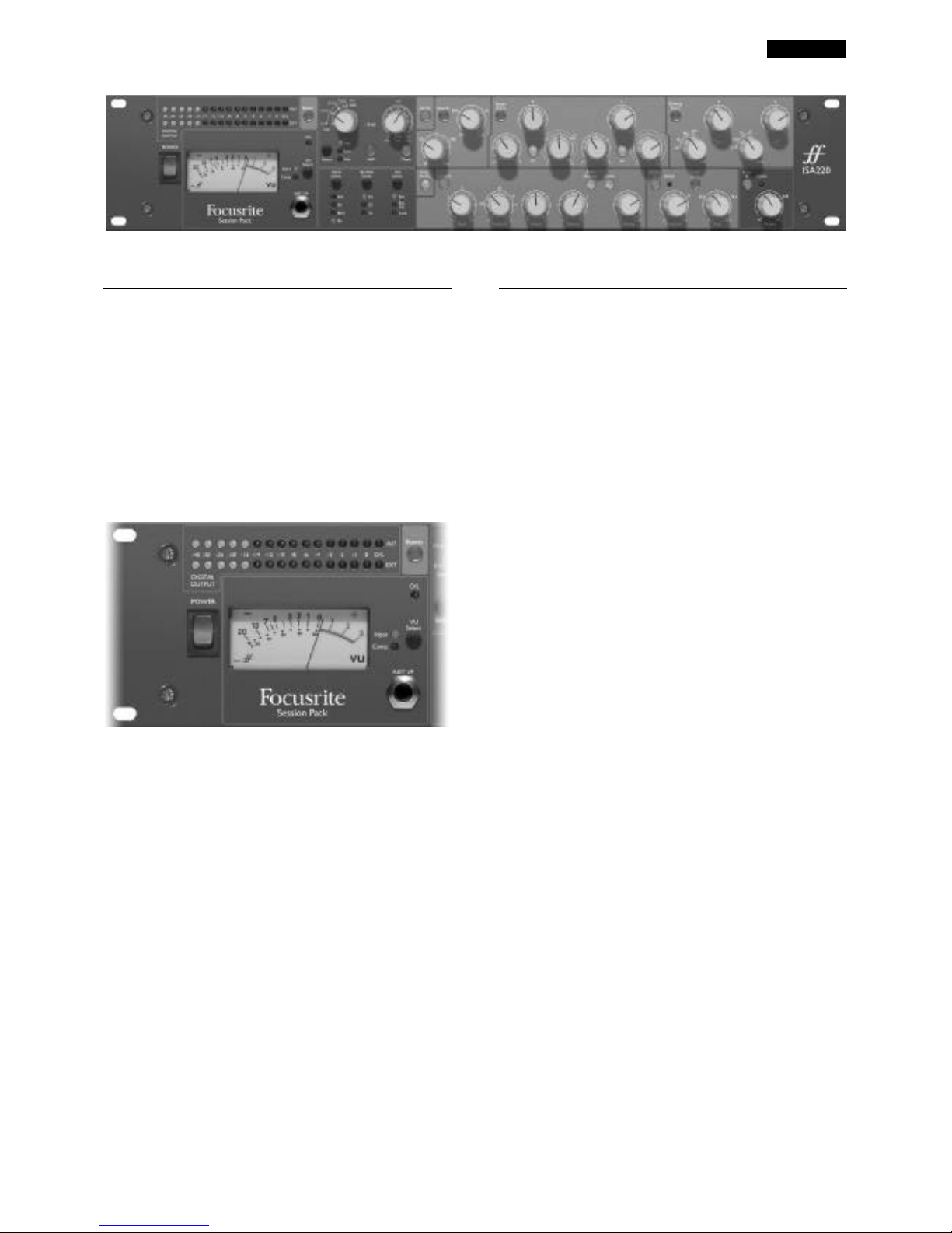
Getting to know the ISA 220
Power
Applies power to the unit. Turn on the ISA 220 before
powering up devices to which the outputs are connected.
Bypass
The processing modules can be globally switched out using
the BYPASS switch, providing a direct route (except for the
signal overload protection of the multi-band limiter, which
remains in the circuit) from the main inputs or External
input, to the A/D inputs. (This enables the unit to be used
as a 24-bit, 96kHz stereo converter for final mastering or
for analogue transfer to digital.)
Metering
VU Select
The VU meter can display input level or the compressor
gain reduction. Press VU SELECT to toggle between the
two sources as indicated by the corresponding LEDs. With
‘Input’ selected, 0VU corresponds to +4dBu. With
‘Compressor’ selected, the meter indicates the amount of
gain reduction caused by compression, from 0VU (no
compression) to -20VU (corresponding to 20dB of gain
reduction).
Note: the VU meter is calibrated at operating temperature.
An ISA 220 will typically take up to 30 minutes to reach
operating temperature. Prior to this the meter may give
slightly lower readings.
Digital Output Meters
Two 16-LED bar graph meters monitor the Internal signal
and the External signal (whatever is connected to the “Ext
A/D IP” XLR input) at a point after the Limiter but before
the A/D input. The meters cover a wide range, with the O/L
LED (see below) acting as an Overload indicator to warn of
excessively high levels at the input of the A/D converters.
O/L LED
This LED illuminates when the peak signal level reaches or
exceeds +20dB, or when the peak signal level reaches 6dB
below clipping. The signal is monitored at three points: after
the input gain TRIM, after the EQ module and after the
Dynamics module, since each module could cause clipping if
incorrectly set up. Occasional short-duration peaks which
may cause the LED to blink will not normally cause audible
distortion, but if the LED is lit constantly, the level in the
appropriate module should be reduced to prevent
overloading.
Inst I/P
Instrument sources may either be connected via the rear
panel ‘Inst Hi Z IP’, or via the front panel ‘Inst I/P’ jack.
Page 4
ENGLISH
4
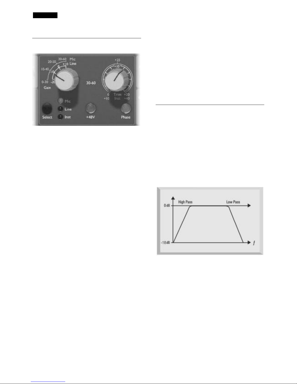
Input Stage
Three input options are provided to give compatibility with
microphone, line or instrument level sources.
Select
Pressing SELECT steps through each of the three inputs as
indicated by the corresponding LEDs. When the Mic LED is
lit, the Mic input is active etc.
Mic Input Gain
With the mic input selected, the user has access to the full
gain range, from 0dB to +60dB, in 10dB steps. With the ‘3060’ switch off, 0dB to +30dB settings are accessible. With
the ‘30-60’ switch on (illuminated), +30dB to +60dB settings
are accessible (yellow legend).
Line Input Gain
With the line input selected, the user has access to gain
settings ranging from –20dB to +10dB (white legend). The
‘30-60’ switch is inactive when the line input is selected.
Instrument Input Gain
With the instrument input selected, gain changes can be
made using the trim control only (see below) which allows
+10dB to +40dB of additional gain. This input is suitable for
high impedance sources such as guitar or bass pickups
(which may be connected directly without the need for an
external DI box), or vintage synthesisers with high
impedance outputs.
Trim
The Trim control provides additional variable gain of 0dB to
+20dB (with mic or line inputs selected – white legend) or
+10dB to +40dB (with instrument input selected – yellow
legend).
+48V
This provides +48V phantom power for condenser mics
when pressed. This switch does not affect the other inputs.
If you are unsure whether your microphone requires
phantom power, refer to its handbook, as it is possible to
damage some microphones by providing phantom power.
Phase
Pressing PHASE inverts the phase of the selected input, to
correct phase problems when using multiple microphones,
or when incorrect wiring polarity has occurred.
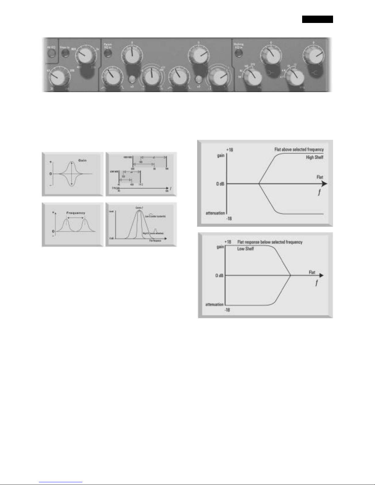
EQ Module
All EQ
Pressing ALL EQ activates all sections of the EQ module
(including the Hi and Lo Pass Filters), placing the whole
module in the audio path. (Also note that each section may
also be switched out of circuit individually.) Toggling ALL
EQ allows A/B comparison of EQ settings without having to
use BYPASS, which switches both EQ and Dynamics
modules in or out of the audio path.
Filter In
Press in to make the Hi and Lo Pass Filters active in the
audio path. Both filters provide 18dB/octave rolloff, and
since the filter frequencies overlap they may be configured
as a very tight band-pass filter.
Low Pass Filter
A variable control sets a rolloff frequency from 400Hz to
22kHz.
High Pass Filter
A variable control sets a rolloff frequency from 20Hz to
1k6Hz.
Page 5
ENGLISH
5
PARAMETRIC EQ
Two separate bands of parametric EQ are provided, each
with continuously variable boost/cut with centre detent,
sweep control with two ranges, and variable Q. The first
band covers the range 40Hz to 400Hz (120Hz to 1k2Hz
when x3 is pressed) and the second band covers 600Hz to
6kHz (1.8kHz to 18kHz when x3 is pressed).
Param EQ In
Press in to switch the Parametric EQ into the signal path.
X3
The Sweep controls have two ranges; the higher being
selected when the x3 switch is pressed (frequencies shown
in yellow on the panel).
SHELVING EQ
High and Low frequency shelving sections are available, each
with continuously variable boost/cut with centre detent, and
a four position rotary switch for selection of rolloff
frequency.
Shelving EQ In
Press in to switch all the Shelving EQ into the signal path.
Page 6

ENGLISH
6
Compressor
Comp Pre EQ
The COMP PRE EQ switch allows the compressor to be
placed before the EQ in the signal path. With this switch
disengaged, the compressor is placed after the EQ (default
position).
Comp In
Press COMP IN to switch the compressor into the signal
path. Note that the VU meter can be selected to display the
compressor gain reduction (see Metering section).
Ratio
The RATIO control determines the rate at which
compression is applied to the signal with increasing input,
and is the ratio of change in input level compared to change
in output level. The control gives a range of 1.5 to 10.
Higher Ratio settings will produce more noticeable
compression, so for the least obtrusive result, the Ratio
should be set at the minimum necessary for the application.
For example, using low Threshold and low Ratio may
produce a less noticeable effect than a high threshold and
high ratio, even though the total amount of compression
may be the same.
Threshold
THRESHOLD determines the level at which compression
begins, with a range -28dB to +12dB. The lower the
Threshold, the more the signal is compressed. Setting a
higher Threshold allows quieter passages in the music or
speech to remain unaffected; only passages that exceed the
Threshold will be compressed.
Attack
ATTACK determines how quickly compression is applied
once the level of the source signal has risen above the
Threshold. When turned anticlockwise the response is very
fast, which tends to make the compressor react to the peak
levels of the signal. This is sometimes desirable, but can
cause unwanted “pumping” of steadier low level
components of the signal by short transients. A slower
attack will cause the compressor to ignore short transients
and respond more to the average loudness of the signal;
however this may seem to increase the relative volume of
the transients.
Page 7

ENGLISH
7
Release
RELEASE determines how quickly compression is removed
once the level of the source signal has fallen below the
Threshold. When in the anticlockwise position, the
compression releases very quickly, which may be
appropriate on rapidly varying signals to avoid compressing
the beats that follow, but can result in excessive distortion
on more sustained material. Clockwise rotation increases
the release time, giving a smoother effect, but which at the
same time may result in transients causing audible
“pumping”.
Auto Release
The AUTO RELEASE switch makes the release time
automatic, substituting an adaptive attack/release circuit,
which essentially varies the release rate to suit the dynamics
of the signal. This enables the use of fast attack times
without any “pumping” type artefacts, especially effective on
complex programme material.
The release rate is probably the most important variable
when recording rock music, since it controls loudness.
Loudness is determined by the maintenance of high mean
levels: compression increases the proportion of high-level
signal content, and as the diagram shows, the faster the unit
releases, the more low-level signal is brought to a higher
level. Therefore, the faster the release rate, the higher the
perceived loudness of the recording.
Blend
This switch, when engaged, mixes the compressed and
uncompressed signals, allowing more of the dynamics of the
original source to be maintained. This simple operation
simulates the common producer’s practice of mixing
compressed and uncompressed signals on two separate
channels of a mixing console.
The unique 'blend' switch on the ISA 220 recombines the
direct unprocessed signal with the post-compression signal
at the gain make-up stage. The direct (uncompressed) signal
is lowered by 6dB to compensate for possible overload. As
the make-up gain is raised, quieter sections of the
compressed audio signal increase in value, while transients
pass without being processed. The result is that the
required reduction in the dynamic range of the signal is
achieved without an overly 'squashed' sound being audible.
Note: when used pre-EQ (COMP PRE EQ switch
illuminated) it may be possible to overload the EQ circuit
when using 'blend.' Hence best results will be obtained with
a post-EQ setting (COMP PRE EQ switch not illuminated.)
Make Up
Compression results in an overall reduction in level. The
MAKE UP control allows you to restore the signal volume
back to the original level. The gain reduction meter is useful
for determining how much make up gain needs to be
applied.
De-esser
The DE-ESSER is based on optical technology, letting you
remove excessive sibilance from a vocal performance (if
“ess” sounds are over-emphasised).
De-Ess In
Press in to activate the de-esser.
Threshold
THRESHOLD determines how much de-essing is being
applied to the selected frequency. The lower the threshold
(control anticlockwise), the more de-essing is applied.
Freq
This control selects a frequency to remove between 2k2Hz
and 9k2Hz.
De-Ess Listen
Press to allow isolated monitoring of only those signals
which will trigger activation of the de-esser, rather than
hearing the overall effect in a complex signal. When the deesser has been set up as desired the switch should be
released.
Page 8

ENGLISH
8
Active LED
This LED illuminates when the de-esser is active at the
chosen frequency, and shines more brightly with increasing
level reduction.
Setting up the de-esser
Press DE-ESS LISTEN with THRESHOLD at maximum and
slowly reduce until the selected frequency begins to trigger
the de-esser. Vary the frequency control to find the exact
area of the signal that you wish to remove. Once located,
switch off DE-ESS LISTEN and adjust THRESHOLD for the
amount of reduction required. No further adjustment of
FREQUENCY should be required, as the hot spot will have
been precisely found using DE-ESS LISTEN.
Limiter
Limit In
Press to activate the multi-band limiter. Three separate
fixed frequency bands with different limiting properties give
true distortion-free limiting.
Active LED
This LED illuminates when the Limiter is active. An upper
threshold is fixed at +20dBu to prevent overload of the
internal (or an external) A/D converter.
Output
A variable control adjusts the ISA 220’s output level
between -60dB and +6dB.
Stereo A/D
The ISA 220 can be used as a high quality stereo A/D
converter for final mastering, or for analogue transfer to
digital, with the addition of the optional ISA 220 digital
output board. The external input, and the line input (when
BYPASS is pressed) are both fed to the A/D inputs, via the
limiter, giving a clean, protected, high quality path to digital.
Digital formats available on the A/D card are AES/EBU,
S/PDIF and 2 channel optical format.
The converter settings accessible on the front panel are as
follows:
Clock Select
Selectable between 44.1kHz, 48kHz, 88.2kHz and 96kHz.
Bit Rate Select
Selectable between 24, 20 and 16 bits.
Ext Select
Selecting EXT allows the ISA 220 to be slaved to an
external wordclock source. Selecting EXT S/C allows the
ISA 220 to be slaved to an external Digidesign Superclock
source.
Page 9

ENGLISH
9
Applications
Record Channel
This example shows the ISA 220 being used for mic or guitar recording.
Stereo A/D Converter
The optional A/D card is a stereo device which can convert two channels simultaneously. Stereo or dual mono conversion can be
accessed by connecting the two audio signals to the EXT A/D IP and INT A/D DIRECT inputs (directly accessing the A/D inputs
via the limiter and digital meters). The INT input of the A/D can alternatively be connected in the normal way via the mic, line or
instrument input, if additional mono processing (EQ and Dynamics) is required on the signal, or if dual mono signals are being
processed by a pair of ISA 220s and converted simultaneously.
Page 10

ENGLISH
10
Stereo ISA 220 Units
It is possible to send audio from an ISA 220 to an A/D card in a second ISA 220 via the EXT A/D input. This configuration creates
a stereo/dual mono record channel with only one A/D Card.
Stereo control of Dynamics section
The example above also shows how to link two ISA 220s together, allowing them to be used as a stereo/dual mono record
channel. The stereo channel can then be routed to a single optional ISA 220 Digital Output Board allowing A/D conversion of the
stereo signal.
Page 11

ENGLISH
11
FAQs
1. Who is the main ‘target audience’ for the
ISA 220?
The ISA 220 was designed primarily for use in high end and project
recording studios, audio/video post-production and voice over facilities etc.
Owing to its combination of a mic pre and a comprehensive range of
processing types, it can be used both for tracking, and as a mix-down tool.
2. What are the main features?
• Many types of class A dynamic and EQ processing in one box
• Focusrite-quality audio throughout, e.g. huge bandwidth: 10Hz-
150KHz
• Focusrite professional Mic Pre (dual-gain transformer-based)
• Upgraded version of the original ISA 130 Class A Focusrite VCA
Compressor
• Focusrite 4-band parametric EQ derived from the original Focusrite
circuit designs
• New opto de-esser utilising phase-cancellation de-ess technology
• New opto multi-band limiter
• Can be used for tracking, mix-down, or as a stereo A/D converter
• Optional 24 bit/96 kHz digital output board
3. Is the EQ based on the original Focusrite
designs?
Yes, the ISA 220’s EQ uses the same EQ curves as those used in the
original Focusrite console, (but with 4-way instead of 6-way shelving
selections.)
4. Is the ISA 220 a Class A device? Why is
that important?
Yes, the ISA 220 is a Class A device. Class A is a type of amplifier design in
which you have a standing DC current running through your amplifier
circuits all the time. As signal arrives, a Class A device varies what is taken
from that standing DC current, rather than switching between supplying a
positive current for one half of the waveform and a negative current for
the other half. This results in the ability to represent audio in a linear
(distortion free) manner all the way through the circuit. Cheaper
processors use IC amplifiers which run close to Class B and don't have the
same standing DC current, which means the transistors inside the chips
switching off and on, inevitably resulting in less linear performance.
5. What if I want my dynamics processing
to occur pre-EQ?
No problem. The EQ and dynamics sections can be switched so that the
dynamics processing precedes the EQ section, (a single push of the ‘PreEQ’ button on the front panel.)
6. Is there any way to configure the ISA 220
as a stereo unit?
Yes. Although a single ISA 220 can act only as a mono unit, it’s possible to
link 2 ISA 220s together, using the ‘dynamic link’ socket on the rear panel.
Using a single stereo TRS jack cable, this allows stereo operation of the
compressor, plus dual mono EQ. You can also use a single ISA 220 as a
stereo A/D converter, (see questions below for a full explanation.)
7. How do I control which ISA 220 will be
the controller and which will be the slave
when using two together for stereo
compression?
Whichever ISA 220 is generating the greater control voltage will be the
controller- So, set one of the ISA 220 compressors to minimum ratio,
maximum threshold, and the other compressor will then always be the
‘controller,’ with any changes made on the controller’s knobs affecting both
channels in the same way.
8. Does the ISA 220 have the same kind of
spectacular bandwidth that has given the
Red Range its reputation for ‘open-ended’
sound?
Yes. The bandwidth of the ISA 220 extends from 10Hz to 150kHz!
9. Can I use all the different sections of the
ISA 220 at once?
Yes. If you want to use the mic pre, hi- and lo- pass filters, parametric and
shelving EQ, compressor, de-esser, limiter and digital output all at the same
time, as one huge ‘super channel,’ you can. You can also take any section
out of the signal path independently with a single button push.
10. What is the ‘blend’ feature in the
compressor section?
The blend feature allows the user to mix uncompressed elements of the
original source signal together with the post-compression signal. The result
achieves the required gain reduction without making the audio sound
‘over-squashed.’
11. Which sections are VCA-driven, and
which use optical technology?
The Compressor uses a VCA, the De-esser and Limiter use optical
technology.
12. Can I use the ISA 220 as a 24/96 stereo
A/D converter?
Yes, the external A/D input, in combination with either the INT A/D direct
I/P, or the mic or line inputs (bypass on,) can be used as a stereo feed to
the optional A/D converter. All inputs also pass through the three-band
limiter before reaching the A/D, preventing digital clipping.
13. Are the ISA 220’s mic and line inputs
transformer-based?
Yes, the ISA 220 comes as standard with mic and line input transformers,
so you are guaranteed the classic ‘warm yet transparent’ Focusrite
signature sound loved the world over. There’s also a MU-metal shielded
power transformer (to prevent hum.)
14. What about metering?
The main input meter can display input level or compressor gain change.
Additionally, there are 16-LED peak-reading output meters for internal and
external signal levels, which measure the output(s) at a point just after the
limiter. You also have an independent overload LED that is fed from 3
different points in the circuit, to warn of overload at the input stage, in the
EQ processor, or in the dynamic processors. There are also status LED’s
for clock select, bit rate select, external sync, and meter select.
15. The limiter is described as ‘frequency
adaptive.’ What does that mean?
It’s a kind of multi-band limiter. Our 3-band "adaptive attack" limiter has
different limiting properties for each of the three frequency bands, giving
true distortion-free limiting. Basically the HF content requires a faster
response from the limiter than the mid or LF, the mid is different from
either HF or LF and so on, so the limiter's slope is designed to be different
for each of the three bands. It's genuinely multi-band, as each of the 3
frequency bands is split, and then sent through different, discrete circuitry.
Thus a large increase in LF will not cause any change in the limiting of the
HF band for example, so the limiter is simple, effective and musical.
16. How does the de-esser work?
The de-esser uses Focusrite’s proprietary phase invert technology. Once
the user has selected the frequency at which the de-ess is to occur, the ISA
220 generates a 180º out-of-phase signal at that frequency which cancels
the specific frequency selected at the moment it occurs, without having a
negative effect on other related frequencies.
Page 12

ENGLISH
12
17. When I travel internationally can I take
my ISA 220 with me?
No problem. The power supply is a multi-tap design, so all you need to do
is turn the fuse holder around (and, if necessary, change the fuse) to change
the voltage to match whichever country you are in.
18. Is there an optional digital output card?
Yes. The card offers a stereo A/D converter, with 24/96 spec (selectable
options from front panel buttons.) The single card fits into the main ISA
220. The card includes a Wordclock input and, uniquely in the processing
world, a Digidesign Pro Tools™ Superclock direct connection via an
additional BNC connector, so that the unit can be slaved to an external
master clock. It allows 16, 20 or 24 bit operation at 44.1, 48, 88.2 and 96
kHz sample rates. Digital audio formats supported are S/PDIF (on single
RCA connector), AES-EBU (on single XLR connector) and optical. The
card can be ordered as part of a ‘digital-ready’ ISA 220 when the main unit
is purchased, or can be retrofitted later. So if you want to take the output
of the ISA 220 to a digital system which doesn't support 24bit 96 kHz, no
problem; you can select any of the range of different clocks and bit rates as
well as choosing to use an external clock source, from the front panel.
19. Why is a Superclock input important?
If a customer has a Pro Tools TDM system and wants to lock it to an
external analogue multi-track (s)he needs a USD, (Universal Slave Driver,
Digidesign’s premier sync box.) This box looks at the speed of incoming
timecode and then varies the Superclock frequency up and down to match.
Therefore, because the Superclock is basically 256 x the speed of
wordclock, the playback or record speed of Pro Tools is matched (very
accurately) to the machine's speed and any attached Digidesign Audio
interfaces will also be adjusted.
If the customer now wants to record off the multitrack into Pro Tools via
an ISA box, they have a problem if they don’t have a Superclock input,
because the ISA would be running off its own internal crystal, and not
looking at the speed information being calculated by the USD. It would be
running at precisely 44.1 or 48k with a very high stability, however the
analogue deck would be ‘wowing and fluttering’ all over the show.
Therefore by providing a Superclock input, you can use the USD to clock
the ISA module, and therefore lock the ISA up to anything you are locking
Pro Tools up to.
Also any TDM Pro Tools equipped with a USD can be switched into
varispeed mode. Using Pro Tools’ Session Setup window, a slider allows
the overall speed of Pro Tools to be moved up or down. This is achieved
by telling the USD to adjust its internal clock and therefore its Superclock
output. This varied Superclock output then feeds any Digidesign interface
as above. So if a customer wants to use an ISA 220, but at the same time
use varispeed in Pro Tools, they need a Superclock input.
20. Is there an optional digital input card?
No, because all the processing in the ISA 220 is entirely analogue - so even
if there were a digital input, the digital signal would have to be immediately
pass through a D/A converter to allow processing!
21. Does the card include dithering?
Yes, the word length of a 24 bit input can truncated down to 20 or 16 bits
and then dithered prior to digital output.
22. Why are the Int A/D and Ext A/D inputs
fed to the digital output card via the
Limiter?
The input to the A/D converter must not exceed 0dBFS in order to
prevent digital clipping. The limiter therefore comes after the A/D
converter inputs so that the user is protected from digital clipping.
23. Can I lock directly to Pro Tools from
the digital output of the ISA 220?
Yes, the digital output board is designed so that it can synchronise to
external wordclock signals, or to Digidesign's Superclock.
24. Why is 24 bit 96 kHz specification
important?
An A/D converter works by sampling the audio waveform at regular points
in time, and then quantising those values into a binary number, which
relates to the number of bits specified. The quantised signal must then be
passed through a D/A converter before it becomes audible. In simple
terms, the D/A essentially ‘joins the dots’ plotted by the A/D converter
when the signal was first converted to digital. The number of dots to join,
combined with how little those dots have been moved, determines how
accurate the final signal will be compared to the original. The greater the
sample rate and bit rate, the more accurate the whole digital process is. So
24 bit/96 kHz performance will ensure more accurate digital transfer of
your audio information compared to the old 16 bit/44.1 kHz standards.
(You can still use these standards for compatibility reasons if you need to,
as the ISA 220 also allows 16 bit/44.1 kHz operation.)
25. Can I retrofit a digital board to an
analogue ISA 220 at a later date?
Yes, and you can do it yourself - it can easily be retro-fitted by the
customer without any soldering etc, just a few screws to undo, and one
clip-connector to join to the main PCB.
26. How would you use the ‘Int A/D direct’
and ‘Ext A/D direct’ inputs on the rear
panel?
The ‘Internal A/D Direct’ input is used to route a signal directly to the A/D
card via the Limiter. It replaces the ‘Internal’ signal feed to the A/D card,
(i.e. whatever is connected to the mic, line or instrument input.) The
External A/D Direct’ input is also used to route a signal to the optional
A/D board card via the Limiter. The signal is fed to the ‘spare’ side of the
A/D card not being used by the internal signal, and so does not replace it.
27. What are the differences between the
ISA 430 and the ISA 220?
The ISA 430 includes an Expander/gate section with sidechain access,
sidechain monitoring, and external keying, and an Insert point which can be
post mic pre/pre EQ, post EQ/pre-compressor, or post compressor/prelimiter. The ISA 430’s EQ is the original Focusrite EQ with 6 frequency
selections for shelving EQ, and frequency-conscious compression and
gating (EQ feeding the sidechain of the compressor or gate) is possible.
The ISA 430’s Split function allows it to be used as two separate channels
for discrete EQ and compression simultaneously. The ISA 430 features
both input AND output transformers (however, note that the ISA 220’s
input transformer also applies to the line input, whereas the ISA 430
transformer is for the mic input only.) There’s also a Post mic pre output
on the rear panel, and the ISA 430’s Instrument input has 10dB more range
(0-40dB on the ISA 430,) but the ISA 430 lacks the ISA 220’s blend
function.
Page 13

ENGLISH
13
Specifications
Signal Connections
Mic IP
Connector: XLR
Signal: Balanced (Transformer)
Operating Level: +4dBu
Maximum IP Level: +26dBu
Gain Range: 0dB to +60dB in 10dB steps
Input Impedance: 1K2Ω
Noise: 128dB EIN with 150W input resistance at 60dB of
gain
THD: 0.0008%
Line IP
Connector: XLR
Signal: Balanced (Transformer)
Operating Level: +4dBu
Maximum IP Level: +26dBu
Gain Range: -20dB to +10 dB in 10dB steps
Input Impedance: 10KΩ
Noise: -96dBu
THD: 0.003% with 0dBu 1kHz input and 20Hz-22kHz
bandpass filter
Inst IP (front and rear panel)
Connector: Mono Jack
Signal: Unbalanced (from any high impedance source such as
guitar or bass pickups)
Operating Level: -10dBu
Maximum IP Level: +10dBu
Gain Range: +10 to +40dB
Input Impedance: >1MW
Output
Connector: XLR
Signal: Balanced
Operating Level: +4dBu
Maximum O/P Level: +26dBu
Ext A/D IP
Connector: XLR/Jack
Signal: Balanced
Operating Level: +4dBu
Maximum IP Level: +22dBu=0dBFs
Int A/D Direct Input
Connector: TRS (Stereo) Jack
Signal: Balanced
Operating Level: +4dBu
Maximum IP Level: +22dBu=0dBFs
Inserting a jack breaks the connection of the A/D input
from the inernal signal path (fed by whatever is connected
to the mic, line or instrument inputs) and routes the signal
from the jack directly to the left channel of the A/D
converter (via the meter and limiter).
Comp Key IP
Connector: TRS (Stereo) Jack
Signal: Balanced
Operating Level: +4dBu
Maximum IP Level: +26dBu
Drives the sidechain of the compressor.
Dynamic Link
Connector: TRS (Stereo) Jack
Links two ISA 220 units, allowing control of the dynamics
sections of each from one unit, giving true stereo dynamics
control.
Compressor
Threshold Range: -28dB to +12dB
Ratio: 1.5:1 to 10:1
Slope: Soft knee
Attack: 500µS to 25mS
Release: 100mS to 7S, variable or auto (program
dependent)
Limiter
Threshold Range: 22dBu
Ratio: ∞ (infinite/brick wall)
Attack: Fast
De-Esser
Threshold Range: 22dBu
Frequency Range: 2K2 to 9K2
Ratio at Centre Frequency: 2:1
Weight
7 kg
Dimensions
484 x 250 x 88 mm
(2U rackmount)
Page 14

ENGLISH
14
Warranty
All Focusrite products are covered by a warranty against
manufacturing defects in material or craftsmanship for a
period of one year from the date of purchase. Focusrite in
the UK, or its authorised distributor worldwide will do
their best to ensure that any fault is remedied as quickly as
possible. This warranty is in addition to your statutory
rights.
This warranty does not cover any of the following:
Carriage to and from the dealer or factory for inspection or
repair.
Labour charge if repaired other than by the distributor in
the country of purchase or Focusrite in the UK.
Consequential loss or damage, direct or indirect, of any
kind, however caused.
Any damage or faults caused by abuse, negligence, improper
operation, storage or maintenance.
If a product is faulty, please first contact the dealer from
which the product was purchased. If the product is to be
shipped back, please ensure that it is packed correctly,
preferably in the original packing materials. We will do our
best to remedy the fault as quickly as possible.
Please help us to serve you better by completing and
returning the Warranty Registration Card, or registering
online at http://www.focusrite.com. Thank you.
Accuracy
Whilst every effort has been made to ensure the accuracy
and content of this manual, Focusrite Audio Engineering Ltd
makes no representations or warranties regarding the
contents.
Copyright
Copyright 2001 Focusrite Audio Engineering Ltd. All rights
reserved. No part of this manual may be reproduced,
photocopied, stored on a retrieval system, transmitted or
passed to a third party by any means or in any form without
the express prior consent of Focusrite Audio Engineering
Ltd.
 Loading...