

Page 1
product information
FOCUS EQ
dB
Mic Input Trim
60
10
20
30
40
50
dB
12
12
7
2.5
2.5
7
+48
-20
-10
-7
-5
-3
-1
0
+1
+2
+3
+
–
Ø Mic Inst
Green 2
Focus EQ
The focus EQ has two main uses
1. Replace a console EQ
2. A high quality recording path for Microphones and
instruments
Better than an average console EQ because:-
More Inputs:-
Mic (A superb quality MicPre
stage)
Line
Instrument (Guitar)
More EQ bands, 6 stages:-
High & Low Filters
High and Low Shelving
Filters
2 Mid Parametric (Bell shape)
EQ can also be switched to either
4 bands of bell shape curves or 2
bands of bell plus 2 bands of
shelving for greater control and
flexibility
Has the legendary Focusrite EQ
sound
Page 2

Page 3

FOCUS EQ
Green Focus EQ (introduction) . . . . . . . . . . . . . . . . . . . . . . . . . . . . . . . . . . . . . . . .4
Section (i): Setting Up
Power Connections . . . . . . . . . . . . . . . . . . . . . . . . . . . . . . . . . . . . . . . . . . . . . . . . . . .4
Power Supply . . . . . . . . . . . . . . . . . . . . . . . . . . . . . . . . . . . . . . . . . . . . . . . . . . . . . . . .5
Signal Connections . . . . . . . . . . . . . . . . . . . . . . . . . . . . . . . . . . . . . . . . . . . . . . . . . . . .5
Section (ii): Functions
Preamplifier . . . . . . . . . . . . . . . . . . . . . . . . . . . . . . . . . . . . . . . . . . . . . . . . . . . . . . . . . .6
Controls . . . . . . . . . . . . . . . . . . . . . . . . . . . . . . . . . . . . . . . . . . . . . . . . . . . . . . . . . . . . . .6
Selecting the input signal . . . . . . . . . . . . . . . . . . . . . . . . . . . . . . . . . . . . . . . . . . . . . . .6
Setting the Gain . . . . . . . . . . . . . . . . . . . . . . . . . . . . . . . . . . . . . . . . . . . . . . . . . . . . . . .7
Setting the Phase . . . . . . . . . . . . . . . . . . . . . . . . . . . . . . . . . . . . . . . . . . . . . . . . . . . . .8
Equaliser . . . . . . . . . . . . . . . . . . . . . . . . . . . . . . . . . . . . . . . . . . . . . . . . . . . . . . . . . . . .8
Low and High Filters . . . . . . . . . . . . . . . . . . . . . . . . . . . . . . . . . . . . . . . . . . . . . . . .9
Controls . . . . . . . . . . . . . . . . . . . . . . . . . . . . . . . . . . . . . . . . . . . . . . . . . . . . . . . . . .9
Using Low and High Filters . . . . . . . . . . . . . . . . . . . . . . . . . . . . . . . . . . . . . . . . .10
Low and High EQ . . . . . . . . . . . . . . . . . . . . . . . . . . . . . . . . . . . . . . . . . . . . . . . .10
Controls . . . . . . . . . . . . . . . . . . . . . . . . . . . . . . . . . . . . . . . . . . . . . . . . . . . . . . . .11
Using the Low and High EQ . . . . . . . . . . . . . . . . . . . . . . . . . . . . . . . . . . . . . . .11
Low Mid and High Mid EQ . . . . . . . . . . . . . . . . . . . . . . . . . . . . . . . . . . . . . . . .12
Controls . . . . . . . . . . . . . . . . . . . . . . . . . . . . . . . . . . . . . . . . . . . . . . . . . . . . . . .12
Using Parametrics . . . . . . . . . . . . . . . . . . . . . . . . . . . . . . . . . . . . . . . . . . . . . . .14
How to use equalisation . . . . . . . . . . . . . . . . . . . . . . . . . . . . . . . . . . . . . . . . . .14
When to use equalisation . . . . . . . . . . . . . . . . . . . . . . . . . . . . . . . . . . . . . . . . .15
Bringing an instrument forward in the mix . . . . . . . . . . . . . . . . . . . . . . . . . . .15
Section (iii): Trouble Shooting
Non-Operation . . . . . . . . . . . . . . . . . . . . . . . . . . . . . . . . . . . . . . . . . . . . . . . . . . . .17
Changing A Fuse
. . . . . . . . . . . . . . . . . . . . . . . . . . . . . . . . . . . . . . . . . . . . . . . . . . . . . . . .17
Worldwide Distributors . . . . . . . . . . . . . . . . . . . . . . . . . . . . . . . . . . . . . . . . . . . . . . . . . . .18
contents
Page 4

Focus EQ
The Focus EQ is a single channel parametric equaliser that you can use to equalise
individual vocals and instruments. It accepts line level input (such as from a tape
machine, high output level instruments, or the insert of a channel), instrument level
input (such as from a guitar), and microphone input.
An equaliser is a sophisticated tone control, that boosts or cuts selected frequency
bands, and so alters frequency response. By modifying different frequency bands in
this way, you modify the tone quality of instruments and vocals, which can fix prob-
lems with the original sound, or for example help a track stand out in the mix. For
more details, see the section How to Use Equalisation.
When you are getting to know the unit, part i c u l a rly if you are not familiar with using a
p a ra m et ric equ a l i s e r , use it on a tra ck that you are familiar with (for exa mple, run a
favo u ri te CD th rough the unit). Try all of the controls in turn, and hear how th ey affe c t
the sound. Wo rking with a familiar tra ck makes inte rp retation of the results easier.
There are two separate parts to the Focus EQ: • Preamplifier • Equaliser
Within the equaliser, there are three types of equalisation:
Low and High filters
Low and High Eq
Low Mid Eq and High Mid Eq (parametrics)
Power Connections
There is an IEC mains lead supplied in the package which should have the correct
moulded plug for your country. The wiring colour code used in all Fo c u s ri te products is:
For units shipped to the USA, Canada, Taiwan and Japan
Live - Black Neutral - White Earth - Green
For units shipped to any other country
Live - Brown Neutral - Blue Earth - Green and Yellow
The chassis is connected dire c t ly to the mains safety earth. We do not provide an earth
l i fting switch, since such a switch can allow for a dangerous wiring arra n g e m e n t .
Warning:For safety reasons, it is absolutely IMPERATIVE that the mains safety earth
is connected.
f o c u s e q
4
Page 5

Power Supply
The Focus EQ will work correctly from either 50 Hz or 60 Hz power supplies, and
draw approximately 35VA from the mains supply at highest load.
The module will operate on a range of voltages, and has a two-position switch on
the rear panel that should be set to the correct voltage:
115V
Set to this position if the module is to be used with
voltages in the range 85V to 120V
230V
Set to this position if the module is to be used with
voltages in the range 200V to 250V
To comply with the safety codes in some countries, modules may be supplied with-
out a voltage selector. In this case, the module is preset to the local supply voltage,
which is clearly marked on the rear of the module. Check that the voltage is set cor-
rectly.
Signal Connections
All the signal connections are via connectors mounted on the rear panel. Standard
XLR connectors are used for all mic and line level signals, and are wired to the AES
standard, which are:
Pin 1 Screen chassis
Pin 2 Live audio 0°
Pin 3 Return audio 180°
For all inputs and outputs, the screen (pin 1 of the XLR) is connected to the chassis
earth point.
In the Green range, jack inputs are used only for external switching applications or
as unbalanced guitar inputs on some units.
When the screen and earth wiring of the module is completed correctly, all modules
which are marked with the European Community CE marking comply fully with the
CE EMC regulations.
s e t t i n g u p
5
i
Page 6
Preamplifier
Controls
The Mic and Input Trim rotary controls set the gain on the input signal (see the sec-
tion Setting the Gain).
+48
is the phantom power button. When lit, it provides phantom power to the
microphone connected to the channel.
Ø
is the phase button, and reverses the phase of the channel when lit (see the sec-
tion Setting the Phase).
The Mic and Inst butto n s select the input signal (see the section Selecting th e
I nput Signal).
Selecting the Input Signal
On the back of the unit are three input sockets:
Mic For microphones only.
Line For line level signals (such as the output from a tape machine).
Inst For instruments (from guitars with single coil pickups to keyboards). Note
that connecting anything into this input disconnects the line input.
f o c u s e q
6
Page 7

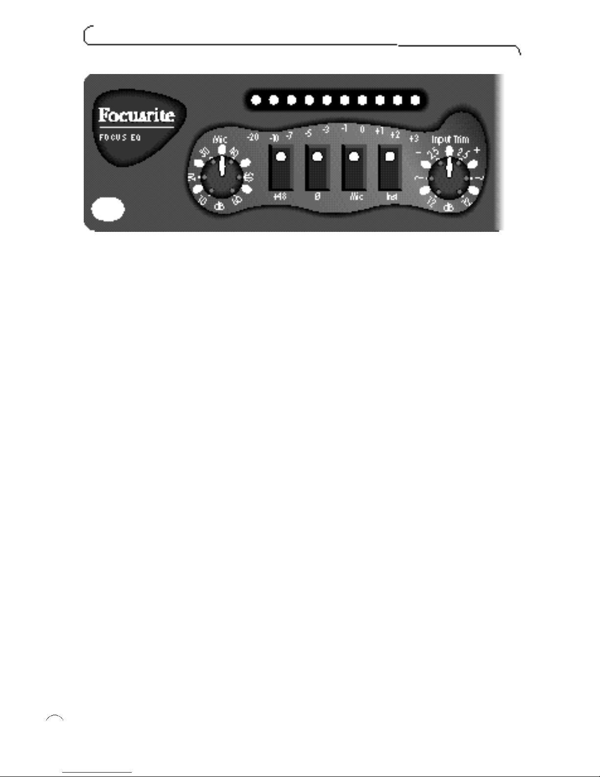
The Mic and Inst switches on the front of the unit determine which of the inputs is
used. The Mic switch is dominant - when it is lit, the Mic input is always used. When
the Mic switch is not lit, the Inst switch determines whether the Inst or Line input is
used: when the Inst switch is lit, the Inst input is used; when the Inst switch is not lit,
the Line input is used. These switch positions are shown in the above diagram:
Setting the Gain
Depending on the input you are using, you may use either the Mic rotary control or
the Input Trim rotary control to set the gain:
Input Rotary control
Mic Mic and Input Trim
Inst or Line Input Trim
Use the meter and the correct rotary control to match the incoming level and gain to
the internal operating level. With an input signal coming into the channel, watch the
meter as you use the rotary control to modify the gain, and set the control so that
the meter registers between -3 VU and 0 VU. This sets the level above the noise
level of the unit, and leaves room for any sudden increase in performance level (it
gives about 20 dB of usable headroom).
Off position: To turn off the Input Trim (for example, when using the mic input), set
the control in its centre (click) position. There is no off position for the Mic rotary
control, since it only operates when using the mic input.
f u n c t i o n s
7
ii
Mic switch lit, Mic input is dominant
Inst switch is lit, the Inst input is used
When the Mic & Inst switch are not
lit, the Line input is used
Page 8

Setting the Phase
When recording a single source using more than one microphone, it is possible for
the signals from the microphones to be out of phase, which affects the quality of the
recording since signals that are out of phase tend to sound “thin”.
For example, when recording a snare drum with two microphones (one on the top of
the snare, the other on the bottom) they will be out of phase. Use the phase switch
to reverse the phase on one of the microphones (but not both) - it normally doesn’t
matter which microphone you reverse. However, if the source is being picked up by
another microphone (for example, by an ambient microphone) then you need to
ensure that you do not put your two close microphones out of phase with the ambi-
ent microphone.
If you think two signals are out of phase, listen for phase as follows:
1. On your monitor system, pan one signal to the left and the other to the right.
2. Use the phase switch to reverse the phase on one of the signals. When the two
signals are in phase, the signal sounds bigger.
Equaliser
Selecting the Type of EQ
The Filters and Eq switches select the type of EQ that is active.
The Filters switch activates the Low and High filters only.
The Eq switch activates the Low and High Eq, and the parametrics.
Therefore, if you want to use all sections of the equaliser, then both switches must
be on.
f o c u s e q
8
Page 9

Low and High Filters
The Low filter allows everything above a certain
frequency to pass through, hence it removes very
low frequency signals. Setting the Low filter to a
certain frequency attenuates (reduces the volume
of) all frequencies below that. Similarly, the High fil-
ter removes high frequency signals, so setting the
High filter to a certain frequency attenuates all fre-
quencies above that.
Controls
Note that you cannot change the amount of attenuation - setting one of these filters
always attenuates the affected frequencies by a preset amount of 12 dB per octave.
For example, setting the High filter at 12 kHz attenuates the signal at 24 kHz by 12
dB and the signal at 48 kHz by 24 dB (for any frequency, the octave above it is at
double the frequency).
Off position: For practical purposes, the off position for the Low filter is 10 Hz, and
for the High filter is 30 kHz.
f u n c t i o n s
9
-12dB
Page 10

Using the Low and High Filters
The Low and High filters are usually used to correct problems with a signal rather
than being used in a creative way (for example, to create a special ef fect).
Use the Low filter to remove:
Unwanted rumble.
Bass lift (a proximity effect of microphones, giving a bass boost as the singer gets
closer to the microphone). This is most apparent with unidirectional microphones.
Hum from noisy sources.
Use the High filter to remove:
Unwanted hiss.
High-frequency bleed-through from other sources when recording bassy signals
(such as bass drum).
A possible creative use of the Low and High filters is to put them full on together,
which gives an effect similar to a telephone or transistor radio.
Low and High Eq
The Low and High Eq are very flexible, as they can be used in either shelf mode or
bell mode. When the switch is not lit, the Low and High Eq are in shelf mode,
which is described in the rest of this section; when the switch is lit, the Low and
High Eq are in bell mode, and act like the parametrics (Low Mid and High Mid Eq),
except that they have a fixed Q. For more details of using parametrics, see the sec-
tion on Low Mid Eq and High Mid Eq.
f o c u s e q
10
Page 11

When in shelf mode, the Low and High Eq affect all frequencies below or above a
given frequency. You can modify the amount of attenuation, or can add gain instead.
Thus, the Low Eq lifts or cuts the low-frequency end of the frequency spectrum, and
the High Eq lifts or cuts the high-frequency end. Using them together you can, for
example, boost the low end and cut the high end of the frequency spectrum, so
appearing to tilt the frequency response towards the low end.
Controls
You can set the frequency and the amount of attenuation or gain applied beyond
that frequency.
sets the Eq to shelf mode or bell mode (as described in the introduction to this
section).
Off position: To turn off Low or High Eq, set the gain control in the middle position,
so that it is neither boosting nor cutting frequencies.
Using the Low and High Eq
Like the Low and High filters, the Low and High Eq are often used to correct problems with a signal:
To comp e n s a t e for a lack of something in the original re c o r ding (for exa mple, if
you had to roll off a lot of bass during re c o r ding because you we re getting a
l ot of bass lift ) .
To replace something you lost in the recording format (particularly top end).
To reduce something excessive (such as a very bassy sound).
Use the Low Eq to boost subsonic information, thus giving a bassy sound, or to
attenuate a sound that is too bassy.
Use the High Eq to boost ambience and reverb in a room, or to attenuate an overbright sound.
f u n c t i o n s
11
Page 12

Low Mid Eq and High Mid Eq
The Low Mid Eq and High Mid Eq are parametrics, which give you control over the
entire frequency spectrum. Unlike the filters, the parametrics affect only a given fre-
quency, plus some frequencies to either side. The range of frequencies affected is
determined by the bandwidth (also known as Q). Low Q has a wide bandwidth, and
high Q has a narrow bandwidth.
Controls
The parametrics let you set every parameter: the gain or attenuation, the frequency
affected, and bandwidth.
t r o u b l e s h o o t i n g
12
iii
Page 13

The Low Mid Eq covers the frequency range from 40 Hz to 1.2 kHz, and the High
Mid Eq covers 600 Hz to 18 kHz. You can see that they o verlap, which gives access
to the middle frequencies from either parametric. For example, this is useful if you
are attenuating a high frequency, but still want to work on the middle frequencies,
since you can use the Low Mid Eq on them.
Note that the control for each parametric does not cover the entire sweep of its
spectrum. Instead, its range is split into two - this means that the control does not
have to cover its entire spectrum in a single sweep, so increasing its sensitivity. Thus,
the Low Mid Eq covers 40 Hz to 400 Hz or 120 Hz to 1.2 kHz, and the High Mid Eq
covers 600 Hz to 6 kHz, or 1.8 kHz to 18 kHz. You determine the range of the
parametric by using the x3 button. When it is not lit, the parametric covers the lower
band, and when it is lit, the parametric covers the higher band.
Off position: To turn off a parametric filter, set the gain control in the middle position,
so that it is neither boosting nor cutting frequencies.
f u n c t i o n s
13
Page 14

Using the Parametrics
Use the parametrics to colour the sound and create a presence. For example, you
can take the sound of an instrument and improve its clarity in the mix. You can also
use the parametrics in narrow Q mode to notch out a frequency (for example, to
remove fret buzz). However, when doing this be careful that you do not adversely
affect the tone elsewhere, since you will affect all occurrences of the selected fre-
quency.
To isolate the frequency you want to boost or cut:
1. Add some gain to the signal, so that you can hear the effect easily.
2. Set a very wide bandwidth (low Q), which again makes it easier to hear the area
you are affecting.
3. Modify the frequency until you find the area you want to work on.
4. Adjust Q and frequency together until you get the desired combination.
5. Modify the gain to control the amount of the selected frequency that is added to
or subtracted from the signal.
How to Use Equalisation
1. When using a microphone, ensure that the microphone placement is correct.
Listen to the sound from the microphones with no equalisation applied, and modify
the microphone placement until you get the sound you want.
2. Set the operating level.
3. Consider what you don’t want (for example, you don’t want too much bass on an
analogue tape machine). This varies with the recording format and varies with the
input signal. If necessar y, use the high- and low-pass filters to remove parts of the
signal.
4. Listen to the ambience and room sound that comes back off tape, and check that
it has the frequency response that you are looking for (for example, the room may be
a bit dull in the top end, or there may be too much bass). If the frequency response
is not correct, use the shelving filters to correct it.
5. Create a sound and bring out the character of the instruments by using the para-
metrics. The figure below shows the frequency range of different instruments. Also
see the section on Bringing an Instrument Forward in the Mix.
6. Set the final output level using the output fader.
f o c u s e q
14
Page 15

When to Use Equalisation
You can apply equalisation when recording or while mixing down a finished track.
You usually record flat (without equalisation) and then apply equalisation at mix-
down, unless you are assigning several instruments to a single trac k, in which case
you need to get the equalisation correct during recording.
Use equalisation to:
Re m ove unwa n ted noise, such as rumble, bass lift and hum (by using the Low fi l te r) .
Reduce hiss (by using the High filter).
Replace missing bass or treble (by using the Low and High Eq).
Reduce excessive bass or treble (by using the Low and High Eq).
Boost room ambience (by using the High Eq).
Improve tone quality (by using all the controls).
Help a track stand out in the mix (by using the parametrics).
Reduce noise and leakage (by using the Low and High filters).
B o o st lows and highs when re c o rding loud acts (by using the Low and High fi lte rs ) .
Bringing an Instrument Forward in the Mix
You can use equalisation to bring an instrument forward in the mix (that is, to make
it easier to hear when mixed with the other instruments). However, when doing this,
beware of using equalisation simply to make the instrument louder by boosting the
fundamental frequency (the musical note).
An instrument’s sound is made up of a fundamental frequency and harmonics, even
when playing a single note, and it is the harmonics that give the note its unique char-
acter. If you use the equaliser to boost the fundamental frequency, you simply make
the instrument louder, and don’t bring it out of the mix. Boosting the harmonic fre-
quencies, on the other hand, boosts the instrument ’s tone quality, and so make it
stand out in the mix. The table overleaf shows useful frequencies for a number of
common instruments.
f u n c t i o n s
15
Page 16

Instrument Tone Quality Useful Frequencies
Voice Presence 5 kHz
Sibilance 7.5 - 10 kHz
Boominess 200 - 240 Hz
Fullness 120 Hz
Electric guitar Fullness 240 Hz
Bite 2.5 kHz
Bass guitar Attack or pluck 700 - 1000 Hz
Bottom 60 - 80 Hz
String noise 2.5 kHz
Bass drum Slap 2.5 kHz
Bottom 60 - 80 Hz
Snare drum Fatness 240 Hz
Crispness 5 kHz
Hi hat and cymbals Shimmer 7.5 - 10 kHz
Clank or bell 200 Hz
Tom toms Attack 5 kHz
Fullness 24Ø Hz
Floor toms Attack 5 kHz
Fullness 80 - 120 Hz
f o c u s e q
16
Page 17

Non-Operation
If none of the LEDs light, check the mains supply:
1. Is the module connected to the mains supply?
2. Is the socket switched off?
3. Is the voltage select switch on the back of the unit in the correct position?
4. If the supply is okay and the module turned on but no LEDs light, then a fuse has
probably blown. See the section on changing a fuse.
Changing a Fuse
We strongly recommend that you do NOT attempt to change fuses unless you are
absolutely certain that you know exactly what you are doing. If you are in any doubt
whatsoever, contact your dealer or the factory before you open the module.
To change a fuse, if you are certain of your technical ability :
1. Disconnect the mains cable.
2. Viewing the module from the back, remove the four screws that secure the
back panel (there are two at each end).
3. Carefully slide out the inside of the unit with a downward motion (see diagram).
4. The fuse is in a holder close to the transformer. To remove the fuse, pull of f
the top of the fuse holder, which holds the fuse.
5. Replace the fuse with a 250 mA anti-surge type.
6. When you have replaced the fuse, slide the inside of the unit back into the
outer cover.
7. Replace the four scr ews in the back panel.
t r o u b l e s h o o t i n g
17
Page 18

Territory Company Contact Address Phone Fax
Austria ATEC GmbH Erich Hofbauer A-2325 Mimberg/Velm, Im Winkel 5 00 43 2234 74004 00 43 2234 74074
Australia AR Audio Engineering G. Maxwell Twartz 558 Darling Street, 00 61 2 9810 5300 00 61 2 9810 5355
Pty. Ltd Balmain, NSW 2041
Belgium TEM Stefaan Hesseas Pontbeeklaan 41, 1731 Zellik, Belgium 00 322 466 5010 00 322 466 3082
Canada Sonotechnique PLJ Inc Gerry Eschweiler 248 The Esplanade, Toronto, 00 1 416 947 9112 00 1 416 947 9369
(Toronto) Ontario M5A 4J6
Patrice Delhaes 200 Gince Street, St Laurent, 00 1 514 332 6868 00 1 514 332 5537
(Montreal) Montreal, Quebec H4N 2W6
Chile Clio Productora Musical Alejandro Lyon Hollanda 1778, Santiago, Chile 00 5622749621 00 56 2274 9575
Croatia Allied Musical Export Misha Vucenovic Auden St. 91, 70197 Stuttgart, Germany 0049 711616692 0049 711616697
Denmark New Music AG Mogens Balle Versterport 8, DK-8000 Arhus C, 00 45 86 190899 00 45 86 193199
Denmark
Finland Studiotec Ky Juha Tamminen Kuusiniemi 2, SF 02710 Espoo 00 358 9 512 3530 00 358 9 512 35355
France Mille et un Sons Gabriel Nahas 2 Villa Ghis, 92400 Courbevoie 00 33 1 46 67 02 10 00 33 1 47 89 81 71
Germany - Sound Service GmbH Lubo d’Orio Bundesallee 86-88, D-12161 Berlin 00 49 30 850 89 50 00 49 30 850 89 589
Greece KEM Thimios Koliokotsis 32 Katechaki Str, 115 25 Athens 00 30 167 48514/5 00 30 167 46414
Holland TM Audio Peter de Fouwe Zonnebaan 52, 3606 CC Maarsenbrock 00 31 30 2 414070 0 31 30 2 410002
Hong Kong Digital Media Technology Clement Choi Flat C, 1/F., Comfort Building 00 852 2721 0343 00 852 2366 6883
86-88 Nathan Road, Tsim Sha Tsui, Kowloon
Iceland Audio Solutions Ari Dan Asvallagata 10, 101 Reykjavik 00 354 896 5626 00 354 421 666 4
Ireland CTI Control Techniques Jim Dunne Fumbally Court, Fumbally Lane, 00 3531 454 5400 00 3531 454 5726
Ireland Dublin 8
Israel Sonotronics Electronic Sonny Shmueli No.2 Y. BIN. NUN St. BNEI-BRAK 00 972 3 5705223 00 972 3 6199297
EquipmentLtd 51261 Israel
Italy Grisby Music Angelo Tordini S.S. 16 Adriatica Km 309, 00 39 71 7108471 00 39 71 7108477
Professional 530 60027 Osimo, Ancona,
Japan Otaritec Satoshi Kasahara 4-29-18 Minami-Ogikubo, Suginami-ku, 00 81 3 3332 3211 00 81 3 3332 3214
Tokyo 167
Korea Best Logic Sound Co Hi Ahn RM #320, Nakwon Bldg., 00 82 2 741 7385 00 82 2 741 7387
284–6 Nakwon-Dong, /7386
Chongno-Ku, Seoul, Korea
New Zealand Protel Rob Paris 15 Walter Street, PO Box 1073, 00 64 4801 9494 00 64 4384 2112
Wellington
Norway Lydrommet Christian Wille Nedregt. 5, 0551 Oslo 5 00 47 22 37 0218 00 47 22 37 8790
Portugal Caius Tecnologias Sandra Serrano R.Sta.Catarina, 131, -4000 Porto, 00 351 2 208 4456 00 351 2 314 760
Portugal
Russia ISPA Alexei Malinin Sredne-Tishinski Per. 00 7 503 956 1826 00 7 503 956 2309
12, Moscow 123557, Russia
f o c u s e q
18
Page 19

Territory Company Contact Address Phone Fax
Singapore Team 108 Technical Kevin Nair 55 Genting Lane, Singapore 1334 00 65 748 9333 00 65 747 7273
Services Private Ltd
Southern Soundfusion Mike Collison PO Box 29147, Melville 2109, 00 27 11 477 1315 00 27 11 477 6439
Africa Johannesburg
Spain Media Sys S.L. Jose Fontanet C/.Rocafort, 11, bajos, int, 08015 00 34 3 426 6500 00 34 3 424 7337
Barcelona
Sweden Tal and Ton Claes Olsson Box 1007, 405 21 Goteborg 00 46 3152 5150 00 46 3152 8008
Switzerland Studio M & M ag Stefan Meier Villa Tannheim, CH 5012 Schonen werd 00 41 62 849 5722 00 41 62 849 3830
Taiwan Advancetek Frank Wang
No 6 Alley 5 Lane 130,
00 886 2716 8896 00 886 2716 0043
International Co.Ltd.
Sec.3 Ming Sheng E. Rd,
Taipei, Taiwan R.O
.C
Thailand KEC M r. Sira Hanbuntro ng 665 Machachai Road Bangkok 10200 00 662 222 8613/4 00 662 225 3173
UK Focusrite Audio Nathan Eames 19 Lincoln Road, Cressex Business Park, +44 (0)1494 462246 +44 (0)1494 459920
Engineering Ltd High Wycombe
Bucks HP12 3RD. England.
USA - Group One Jack Kelly - New York 80 Sea Lane Farmingdale, 00 1 516 249 1399 00 1 516 753 1020
NY 11735
Chris Fichera - CA 201 Wilshire Blvd., Suite A-18, 00 1 310 656 2521 00 1 310 656 2524
Santa Monica, CA 90401
w o r l d w i d e d i s t r i b u t o r s
19
Page 20

n o t e s
Page 21

n o t e s
 Loading...