

Page 1

Table of Contents
Warranty 3
Warranty Registration/Inspection Form 4
Sign Off Form 5
Introduction 6
Safety 7
Safety Decal Information 8
Assembly & Installation 9
Handler I Installation 9
Handler II Installation 14
Handler III Installation 20
Operation 28
Troubleshooting 36
Handler I Manifold Venturi Package Breakdown 38
Handler I Threaded Venturi Package Breakdown 39
2” Handler II & III Manifold Venturi Package Breakdown 40
3” Handler III Manifold Venturi Package Breakdown 41
Handler I, II & III Tank Parts Breakdown 42
System Specifications 43
Plumbing Package Assembly 44
Plumbing Package Operation 46
1Handler I, II & III Operator’s Manual - October 2008
Page 2

Page 3

Warranty
Focus Industries Inc. products are warranted for one year from date of purchase against
defects in material and workmanship and to perform according to specifications when
such products are properly assembled, installed, used and maintained. Warranty is
granted to original owner only.
Our obligation under this warranty is limited to repairing or replacing, at our option,
and excluding pumps, within 12 months of the retail delivery date. This obligation shall
not include any transportation charges or costs, or any liabilities for direct, indirect or
consequential damage or delay.
Warranty Limited or Void
Any use for purposes other than those for which the product was designed, operation beyond rated capacity, substitution of parts not approved by focus industries Inc., or alteration or repair by others in such manner as in our judgment affects the product materially
and adversely shall void this warranty.
Warranty does not apply to any machine or part which has been repaired or altered in
any way so as in the company’s judgment affects its reliability, or which has been subject to misuse, negligence or accident.
Furthermore, component parts, equipment, accessories and items not fabricated by
Focus Industries Inc. are warranted only to the extent of the original manufacturer’s
warranty.
The gas and diesil engines, electric and hydraulic motors that are included with our pumps
are warrantied by the engine manufacturer, not by Focus Industries Inc. Please refer all
engine warranties to the authorized engine dealer near you.
Focus Industries Inc. reserves the right to make improvement changes on any of our
products without notice.
Warranty Claims Procedure
A warranty claim form must be completed at your handler dealer.
1.
Defective parts for which a warranty claim is made must be returned to the dealer
2.
within 15 days from the claim date.
3Handler I, II & III Operator’s Manual - October 2008
Page 4

Warranty Registration/Inspection Form
Warranty Registration
This form must be filled out by the dealer and signed by both the dealer and the customer at the time of delivery.
Customers Name Dealer Name
Address Address
City, State, Code City, State, Code
Phone Number Phone Number
Delivery Date Check One: Commercial Use Farm Use
Serial Number of Unit
Dealer Inspection Report Safety
Frame Fasteners Tight All Decals Installed
Chemical Hoses Tight Review Operating & Safety Instructions
Oil in Engine
I
the operator’s Manuel content, equipment care, adjustments, safe operation and applicable warranty policy.
Date Dealer’s Rep. Signature
Th
safe operation and applicable warranty policy.
Date Owner’s Signature
4 Handler I, II & III Operator’s Manual - October 2008
Page 5

Sign Off Form
Focus Industries Inc. follows the safety standard specified by the
American Society for Agricultural Engineers (ASAE) and the
Occupational Safety and Health Administration (OSHA). Anyone who will be operating and/or maintaining the Handler must
read and clearly understand ALL safety, operating and maintenance information presented in this manual.
Do not operate or allow anyone else to operate this equipment
until such information has been reviewed. Annually review this
information before season start up.
Date Employee Name Employee Signature
Make these periodic reviews of Safety and Operation a standard
practice for all equipment. We feel that an untrained operator is
unqualified to operate this equipment.
A sign off form is provided for your record keeping to show that
all personnel who will be working with the equipment have read
and understood the information in the Operator’s Manual and
have been instructed in the operation of the equipment.
5Handler I, II & III Operator’s Manual - October 2008
Page 6

Introduction
Congratulations on your choice of a Focus Industries Inc.
Handler.
Safe, efficient and trouble-free operation of your Handler
requires that you and anyone else, who will be operating
or maintaining the system, read and understand the safety,
operation, maintenance, and troubleshooting information
contained in the Operator’s Manual.
Safety
Safety Alert Symbol
Keep this manual handy for frequent reference and to pass on to
new operators and owners.
Operator Orientation
Left Right
Why is SAFETY important to you?
This Safety Alert symbol means Attention! Become Alert! Your
Safety is involved!
The Safety Alert symbol identifies important safety messages on
the Focus Industries Inc. Handler. When you see this symbol,
be alert to the possibility of personal injury or death. Follow the
instructions in the safety message.
3 Big Reasons
Accidents Disable and Kill
1.
Accidents Cost
2.
Accidents Can Be Avoided
3.
Signal Words
The directions left, right, front, and rear, as mentioned
throughout this manual, are seen from the operator’s position
facing the front of the Handler tank. With the proper orientation,
the Handler name will be clearly visible on the front of the tank.
6 Handler I, II & III Operator’s Manual - October 2008
Page 7

Note the use of the signal words Danger, Warning and Caution
with the safety messages. The appropriate word for each message has been selected using the following message has been
selected using the following guidelines:
You are responsible for the safe operation and maintenance of
your Focus Industries Inc. Handler. Ensure that you and anyone
else who is going to operate, maintain, or work around the Handler be familiar with the operating and maintenance procedures
and related safey information contained in this manual. This
manual will take you step by step through your working day and
alert you to all good safety practices while operating the Handler.
Remember you are the key to safety. Good safety practices not
only protect you but also the people around you. Make these
practices a working part of your safety program. Be certain that
everyone operating this machine is familiar with the procedures
recommended and follows safety precautions. Remember, most
accidents can be prevented. Do not risk injury or death by ignoring good safety practices.
General Safety
Read and understand the Operator’s Manual and all safety
•
signs before operating, maintaining, adjusting or unplugging
the Handler.
Only trained competent persons shall use the Handler. An
•
untrained operator is not qualified to use the tank.
Have a first aid kit available should the need arise and know
•
how to use it.
Have a first aid kit available
Wear appropriate protective gear. This includes, but is not
•
limited to:
A Hard Hat
•
Protective shoes with slip resistant soles
•
Protective glasses or goggles
•
Rubber or neoprene gloves
•
Wet weather gear
•
Hearing protection
•
Respirator or filter mask
•
Handler owners must give operating instructions to operators or
employees before allowing them to operate the Handler. Continue doing this on an annual basis.
The most important safety device on this equipment is a safe operator. It is the operator’s responsibility to read and understand
all safety and operating instructions in the manual and to follow
them. All accidents can be avoided.
A person who has not read and understood all operating and
safety instructions is not qualified to operate the machine. An
untrained operator exposes himself and bystanders to possible
serious injury or death.
Do not modify the equipment in any way. Unauthorized modification may impair the function and/or safety and could affect the
life of the equipment.
Think Safety! Work Safely!
Wear appropriate gear
Before starting, read chemical manufacturers’ warnings,
•
instructions and procedures and follow them exactly.
Post the Poison Control Emergency telephone number for
•
your area on your sprayer before using Agricultural products. The appropriate number can be found in the inside
of your telephone book. Have container label handy when
seeking medical attention.
Review all safety related instructions with all personnel
•
annually.
Do not put hands into the Handler when adding products.
•
Wear safety goggles, rubber gloves and protective clothing
•
7Handler I, II & III Operator’s Manual - October 2008
Page 8

whenever working with the Handler or on a machine or a
component containing toxic product.
Keep all shields and guards in place when operating.
•
Clear the area of all bystanders, especially children, before
•
starting.
Review safety instructions annually
•
Safety Decals
Keep safety decals and signs clean and legible at all times.
•
Replace safety decals that are missing or have become illeg-
•
ible.
Replaced parts must have current safety decal.
•
Safety decals or signs are available from your dealer parts
•
department.
How to Install Safety Decals
Be sure that the installation area is clean and dry.
1.
Decide on the exact position before you remove the backing
2.
paper.
Remove the smallest portion of the split backing paper.
3.
Align the decal over specified area and carefully press the
4.
small portion with the exposed sticky backing in place.
Slowly peel back the remaining paper and carefully smooth
5.
the remaining portion of the decal in place.
Small air pockets can be pierced with a pin and smoothed
6.
out using the piece of decal backing paper.
Safety Decal Information
The types of decals on the equipment are shown in the illustrations below. Good safety requires that you familiarize yourself
with the various safety decals, the type of warning and the area,
or particular function related to that area that requires your safety
awareness.
Handler safety decals
Think Safety! Work Safely!
8 Handler I, II & III Operator’s Manual - October 2008
Page 9
Assembly & Installation
Threaded System
About Your Handler
Model Type
You have purchased a Handler I, Handler II or Handler III. All
components required to install the unit are included in the package except for the fittings used to join the Handler tank to the
existing sprayer lines. Purchase these from your dealer as the
size may vary between make and model of sprayer.
Valve System
All systems have been equipped with a venturi or plumbing
valve system. Identify precisely the model type and valve system
you have purchased before you begin assembly and installation
Assembly and installation procedures are specific to each model
type and valve system. Because installation varies, the assembly
instructions and illustrations will separately detail the installation
of each model type.
Handler I Assembly
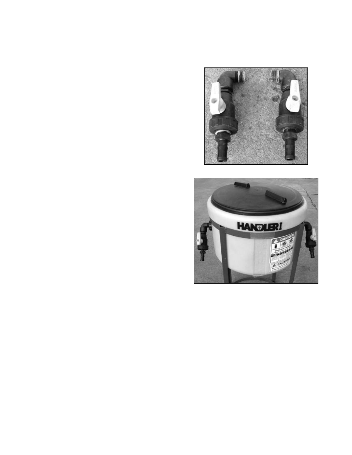
Step 1
Agitation and rinse valve installation
Figure H1-4.1
Overview
Assembly and instructions of your Handler 1-i15T threaded version follows five basic steps:
Install agitation and rinse valve assemblies onto side of
1.
tanks.
Install venturi valve assembly with venturi onto bottom of
2.
tank.
Install venturi bracket onto Handler frame.
3.
Install bypass valve assembly.
4.
Install hoses and clamps.
5.
Assembly and instructions of your Handler 1-i15M Manifold
version follows five basic steps:
Assemble and install agitation and rinse valve assemblies
1.
onto side of tanks.
Assemble and install venturi valve assembly with venturi
2.
onto bottom of tank.
Assemble and install remaining manifold fittings.
3.
Install venturi bracket onto Handler frame and bolt down
4.
manifold fittings to bracket.
Install hoses and clamps.
5.
Figure H1-4.2
Thread agitation valve assembly (See Fig. H1-4.1) into the
1.
¾ bulkhead on the left side of the tank. (See Fig. H1-4.2)
Note: Apply sealant before installing (as per sealant
•
notes on page 37.)
Install assemblies so that the hose barb points to the front.
2.
(Bracket side of tank.) (See Fig. H1-4.2)
Thread rinse valve assembly (See Fig. H1-4.1) into the ¾”
3.
bulkhead on the right side of the tank. (See Fig. H1-4.2)
Note: Apply sealant before installing (as per sealant
•
notes on page 37.)
Install assemblies so that the hose barb points to the front.
4.
(Bracket side of tank.) (See Fig. H1-4.2)
9Handler I, II & III Operator’s Manual - October 2008
Page 10
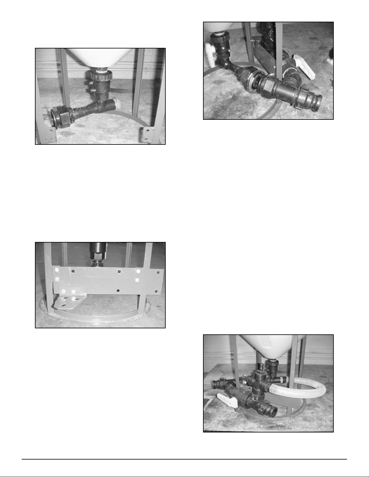
Step 2
Venturi package assembly
Figure H1-4.3
Thread venturi assembly to anti-vortex fitting on tank bot-
1.
tom. Be sure to use sealant as per instructions.
NOTE: the discharge end of the venturi once installed
•
should point to the left hand side behind tabs. (See Fig.
H1-4.3)
Figure H1-4.5
Attach bypass valve assembly to venturi assembly using
4.
stainless steel flange clamp (25-FC200) and gasket (25150G) making sure that the 2” ball valve (10-10230) sits on
the support bracket. Do not tighten clamp completely yet.
(See Fig. H1-4.5)
Step 4
Bypass valve installation
Step 3
Bracket installation
Figure H1-4.4
Install venturi bracket to tabs on the Handler frame as
2.
shown in Fig. H1-4.4 using ¼” x 1” bolts. Do not tighten
completely yet.
Install smaller ball valve support bracket on to venturi
3.
bracket using 5/16” x ¾” bolts. Do not tighten completely
yet. (See Fig. H1-4.4)
Fasten 2” ball valve to support bracket using 5/16” x ¾”
1.
bolts, 3/8 flat and 5/16 lock washer.
Tighten all bolts and clamps.
2.
Step 5
Hose and clamp installation
Thread female end of hose barb on venturi hose assembly
1.
on the intake side of the venturi (86-HV150).
Note: Use Sealant on both male and female threads.
•
Important: Make sure venturi nozzle is in place before
installing venturi hose.
Figure H1-4.6
10 Handler I, II & III Operator’s Manual - October 2008
Page 11
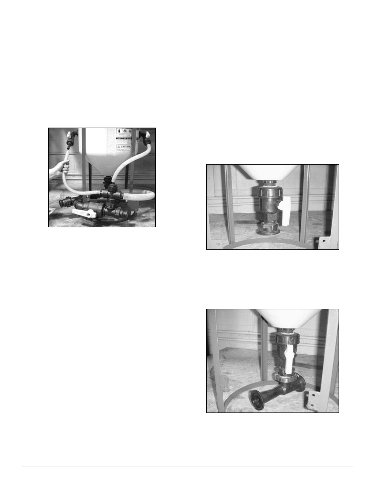
Attach the other end of the venturi hose assembly to the
2.
bypass assembly. (See Fig. H1-4.6) Fasten hose with MC24
hose clamps (54-75624)
Cut and attach the appropriate length of ¾” hose (54-79200)
3.
to connect the hose barb on the agitation valve assembly to
the hose barb on the top left hand side of the bypass assembly. (See Fig. H1-4.7) Fasten hose with MC12 hose clamps
(53-75612)
Step 5
Hose and Clamp Installation
Manifold System
Step 1
Agitation & rinse valve installation
Assemble and thread agitation valve assembly (see Fig.
1.
H1-4.1) into the ¾ bulkhead on the left side of the tank. (See
Fig.4.2 H1-4.2)
Note: Apply sealant before installing.
•
Install assemblies so that the hose barb points to the front.
2.
(Bracket side of tank.) (See Fig. H1-4.2
Thread rinse valve assembly (See Fig. H1-4.1) into the ¾”
3.
bulkhead on the right side of the tank. (See Fig. H1-4.2)
Step 2
Venturi assembly
Figure H1-4.7
Cut and attach the appropriate length of ¾” hose to connect
1.
the hose barb on the rinse valve assembly to the hose barb
on the top of the bypass assembly. (See Fig. H1-4.7) Again
fasten hose with MC12 hose clamps.
Tighten all fittings, bolts and hose clamps as necessary.
2.
NOTE: Also check fly nut on anti-vortex fitting on tank
•
bottom. Tighten as necessary using pump pliers.
Your Handler 1-i15T is now completely assembled. Instructions
for the manifold package will follow. You may now continue to
the operation section of the manual starting on page 28.
Figure H1-4.8
Thread venturi valve assembly on to anti-vortex fitting on
1.
tank bottom. Position valve handle for easy access.
(See Fig H1-4.8)
NOTE: Be sure to use sealant as per instructions
•
Figure H1-4.9
Attach venturi to valve assembly flange with clamp and gas-
2.
ket. Do not tighten completely yet. Position discharge end
of venturi so it points to the front left (in-between the tabs
welded on the frame). (See Fig H1-4.9)
11Handler I, II & III Operator’s Manual - October 2008
Page 12
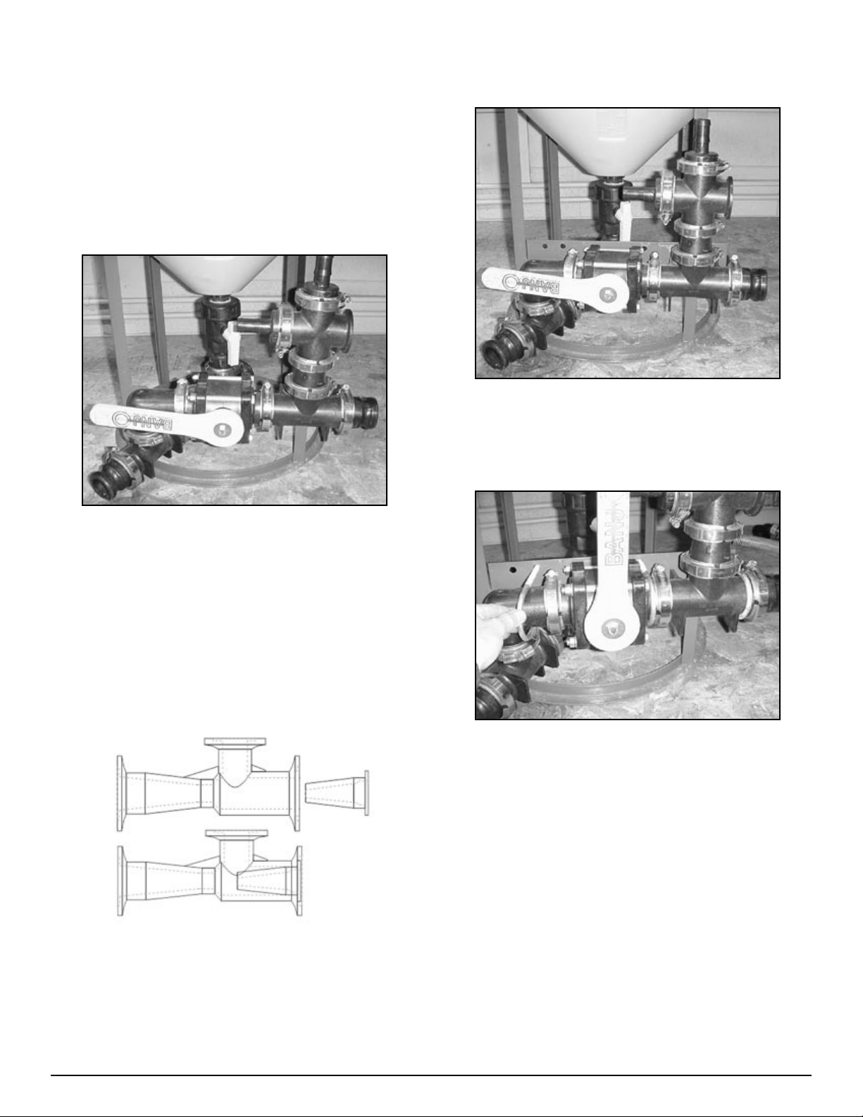
Step 3
Bypass valve installation
Attach coupler (25-M220200CPG) to discharge end of ven-
1.
turi using (25-FC200) flange clamp and (25-150G) gasket.
Attach 2” manifold tee (25-M220TEE) to coupler using (25-
2.
FC220) flange clamp and (25-200G) gasket. Make sure stem
of tee is pointed upwards.
Step 4
Bracket installation
Figure H1-4.11
Install venturi bracket (86-H1i15VBPO) to tabs on Handler
1.
frame as shown in Fig. H1-4.11 using ¼” x 1” bolts. Do not
tighten completely yet. (See Fig. H1-4.11)
Figure H1-4.10
Position manifold tee so it is tight against the left hand side
3.
of the front (in-between tabs welded on the frame.) (See Fig.
H1-4.10)
Continue attaching manifold fittings using the appropriate
4.
clamps and gaskets as shown. (See Fig. H1-4.10)
Note: Make sure venturi nozzle is in place before install-
•
ing venturi hose. Make sure arrow on venturi (Flow
direction) is pointed to the front.
Figure H1-4.12
Attach completed assembly to venturi bracket (86-
2.
H1i15VBPO) using 3/8”x 2 ½” U-bolts (67-UB38-250)
(See Fig. H1-4.12)
Tighten all bolts and clamps
3.
Venturi Nozzle Placement
12 Handler I, II & III Operator’s Manual - October 2008
Page 13
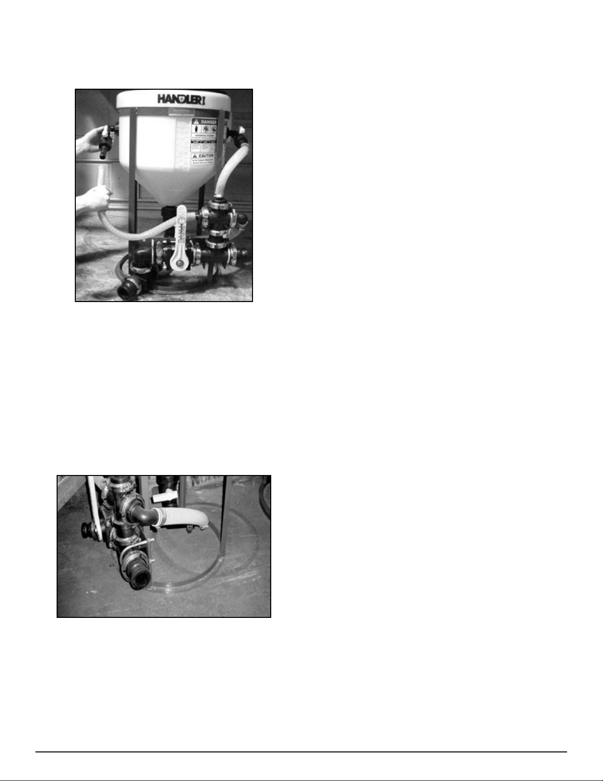
Step 5
Hose and clamp installation
Figure H1-4.13
Cut and attach the appropriate length of 1” hose (57-79210)
1.
to connect the hose barb on the top left hand side of the
bypass assembly. Fasten hose with MC12 hose clamps (53-
75612) (See Fig. H1-4.13)
Cut and attach the appropriate length of 1” hose to connect
2.
the hose barb on the rinse valve assembly to hose barb on
the rinse valve assembly to the hose barb on the top of the
bypass assembly. Again fasten hose with MC12 clamps.
(See Fig. H1-4.13)
Tighten all fittings, bolts and hose clamps as necessary.
5.
Note: Also check flynut on anti-vortex fitting on tank bottom. Tighten as necessary using pump pliers.
The assembly of your Handler 1-i15M is now complete.
6.
Continue to the operation section of the manual on page 28.
Figure H1-4.14
Measure, then cut and attach the appropriate length of 1 ½”
3.
PVC suction hose (54-79050) to connect the venturi to the
manifold fitting assembly. (See Fig. H1-4.14) Fasten with
MC24 hose clamps (53-75624).
Hint: warm hose ends and barbs before trying to install the
4.
hose. In addition, silicone spray can be applied to hose ends
to make installation easier.
13Handler I, II & III Operator’s Manual - October 2008
Page 14
Handler II Assembly
Overview
Assembly of your Handler 2 (without pump) follows four basic
steps:
Rinse valve and agitation fitting assembly and installation.
1.
Venturi bracket and plate installation.
2.
Three way valve support bracket installation
3.
Venturi package assembly and installation.
4.
If you have purchased a Handler 2 with a pump or recirculation
package then there are two additional Steps:
Pump bracket installation.
1.
Pump and recirculation package installation.
2.
Step 1
Rinse valve and agitation fitting assembly
and installation
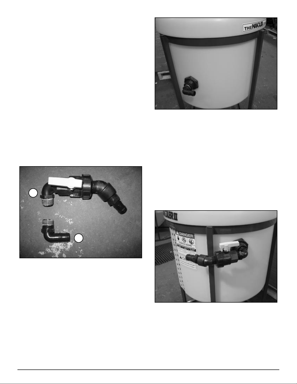
B
Figure H2-4.2
Rinse Valve Assembly (Figure H2-4.1, “B”)
Install one 1” MPT X 1” MPT elbow (10-10980) on to 1”
1.
single union ball valve (25-UV100FP) on end opposite of
union. (Apply sealant before assembling - see notes on
page 37)
Install 1” MPT X 1” Hose Barb (25-HB100) onto end of
2.
street elbow.
Install 1” street elbow 45 degree (25-SL100-45) into union
3.
side of ball valve.
Attach the above assembly to 1” bulkhead on right side of
4.
tank (see figure H2-4.3).
A
FIgure H2-4.1
Agitation Fitting Installation (Figure H2-4.1, “A”).
Install 1” MPT X 1” HB 90 (25-HB100-90) on to 1” bulk-
1.
head on left side of tank. See figure H2-4.2. (Apply sealant
before assembling - see notes on page 37)
Figure H2-4.3
14 Handler I, II & III Operator’s Manual - October 2008
Page 15
Step 2
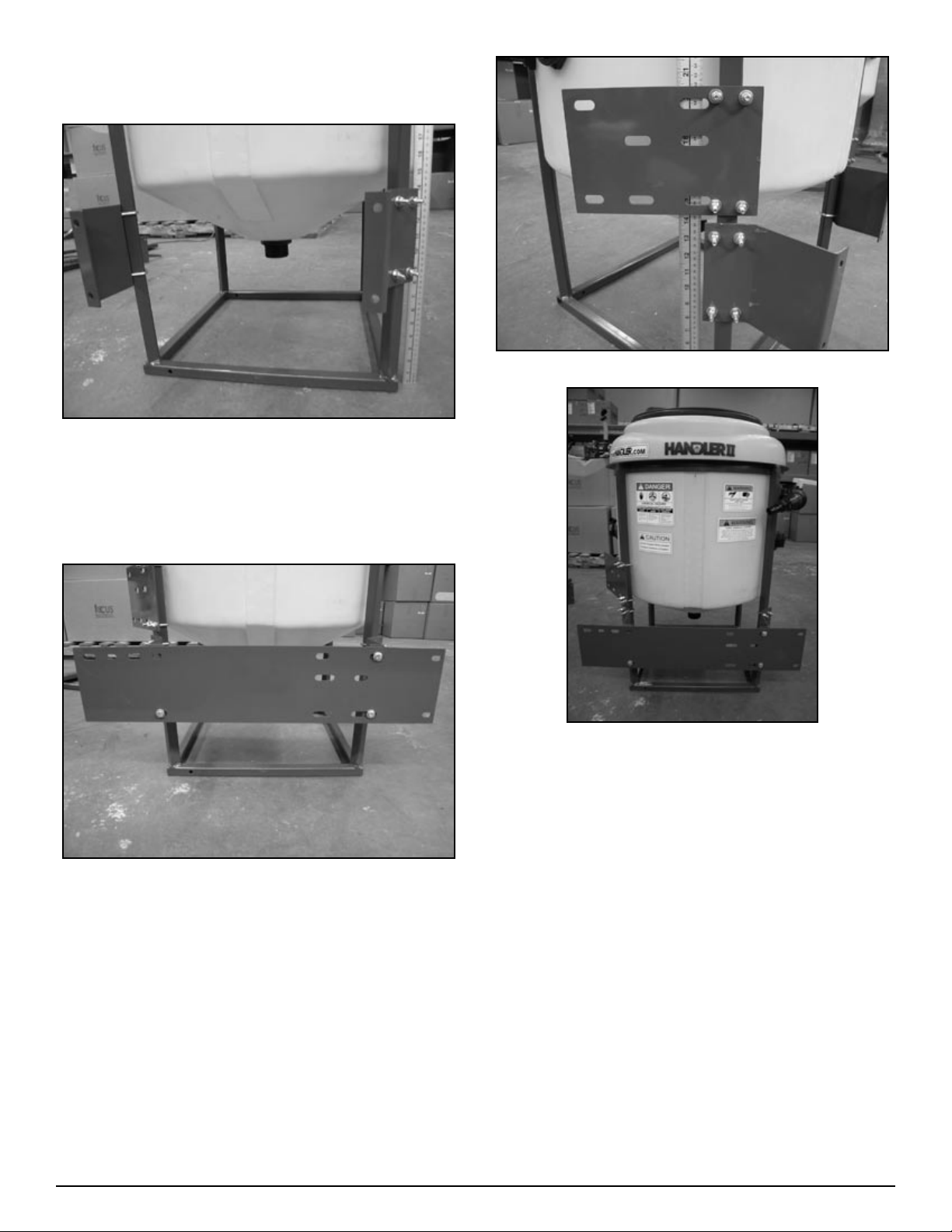
Venturi bracket and plate installation
Figure H2-4.4
Mount angled frame brackets (86-HAFB) to frame as shown
1.
in figure H2-4.4. Use two 1” U-bolts (67-UB025-100) per
bracket. Bottom of bracket should be 7” from bottom of
frame. NOTE: Tighten only enough to prevent slipping.
Figure H2-4.6
Figure H2-4.5
Mount venturi mounting plate (86-HVMP) on to angled
2.
frame brackets as shown in figure H2-4.5 . Use three 5/16”
X 1” bolts (67-CSH5C516-1p) – two on the right side and
one on the lower left side. Do not tighten completely yet.
Hint: if angle frame brackets are not perpendicular to frame
tap with a mallet to align them.
Figure H2-4.7
Mount intake support plate (86-HISP) to frame 14 1/2” from
3.
the base as shown in figure H2-4.6 and H2-4.7. Use two 1”
U-bolts (67-UB025-100). Do not tighten completely yet.
Go to next step (Three way valve support bracket installa-
4.
tion).
15Handler I, II & III Operator’s Manual - October 2008
Page 16
Step 3
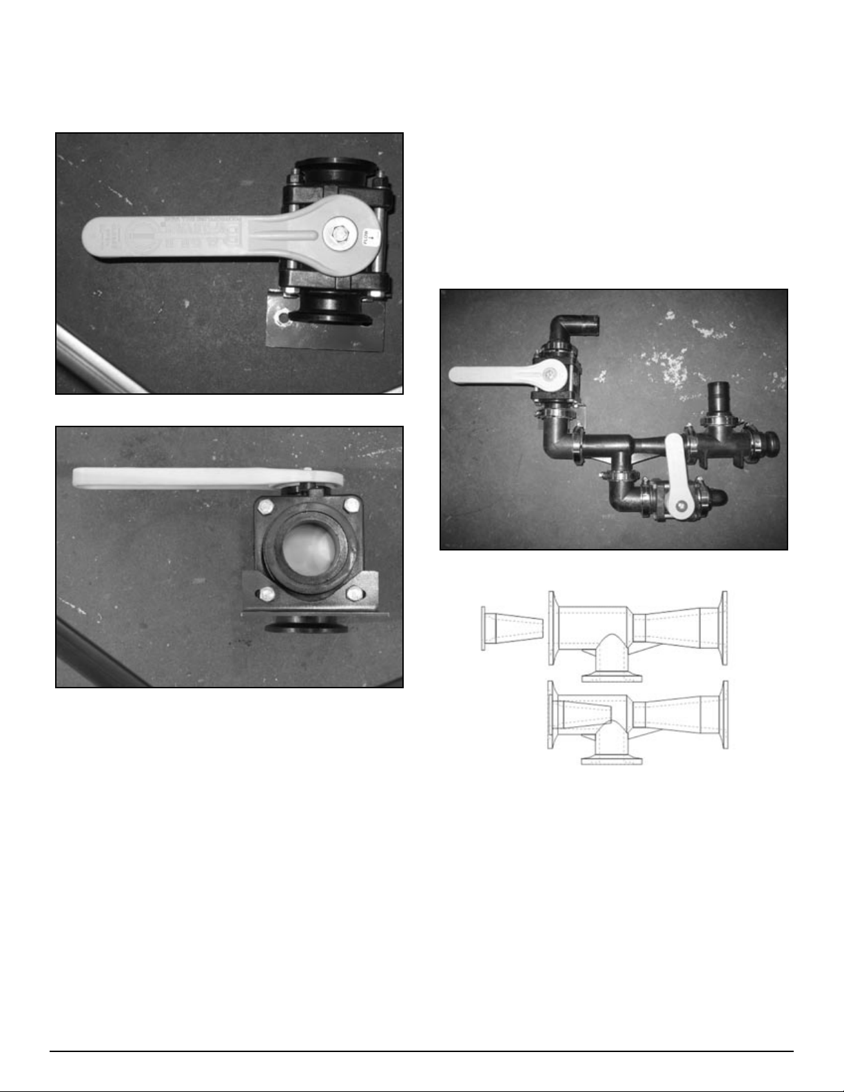
Three way valve support bracket
installation
Figure H2-4.22
Part Number 25-M220CPG90 has long and short side. At-
•
tach short side to venturi and long side to 3 way ball valve
(25-MV220BL) as shown in figure H2-4.8
Start assembly at discharge end and work towards other end
•
(intake).
Venturi comes with nozzle insert, will not run without.
•
Do not install 2” bypass hose (54-79250) until last.
•
Warm hoses before installing – use heat gun or pail of hot
•
water.
Lubricate hose barbs with liquid dish soap or silicone based
•
lubricant to make installation easier.
Assemble and install 1” fittings last.
•
Figure H2-4.23
Install 2” three way valve support bracket (86-VASB2) on
1.
to three way valve as shown in Figure H2-4.22 and H2-4.23
NOTE: handle operation should have closed position to left
when looking at front of valve.
Go to next Step (Venturi package assembly and installa-
2.
tion).
Step 4
Venturi package assembly and installation
Hints:
Lay all parts out first.
•
Open FC200 and FC220 clamps slightly larger to make as-
•
sembly easier.
Open FC100 clamps completely to make assembly easier.
•
Figure H2-4.8
Venturi Nozzle Placement
Assemble manifold venturi package as shown in figure H2,
1.
H3-4.8. Do not tighten completely yet.
16 Handler I, II & III Operator’s Manual - October 2008
Page 17
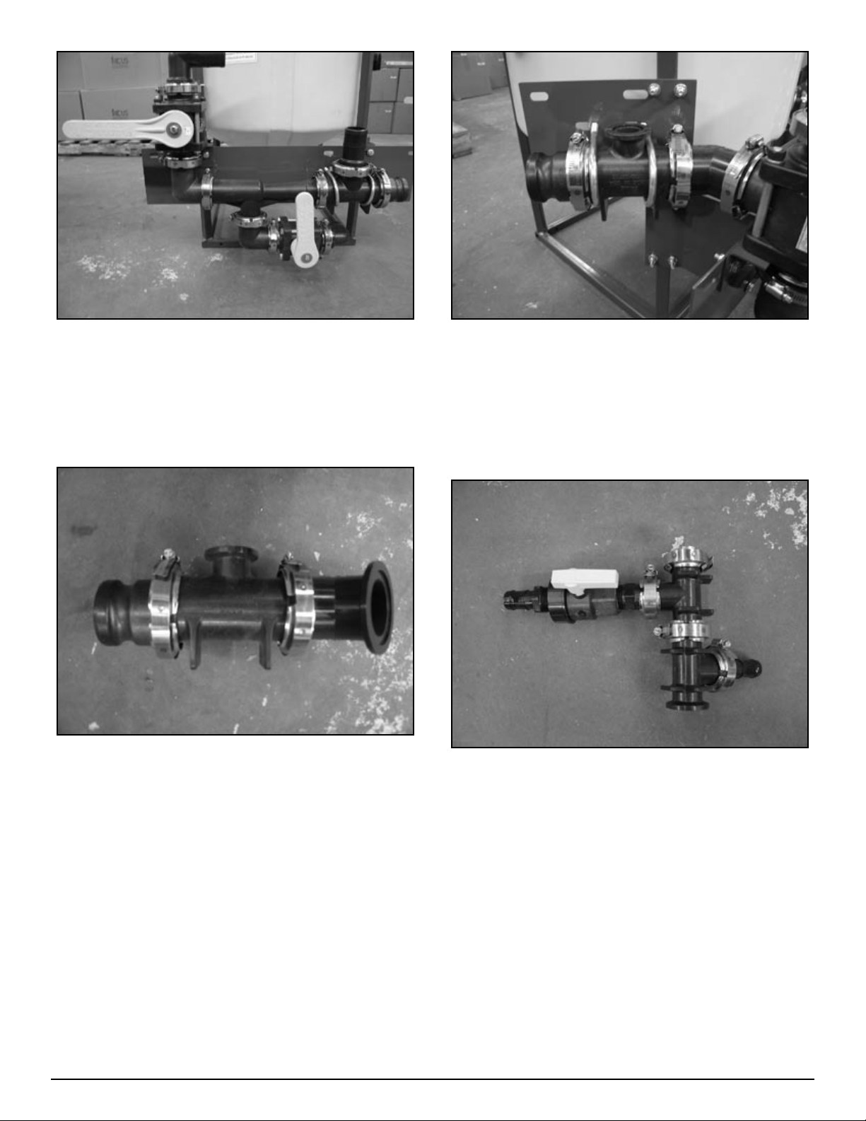
Figure H2-4.9
Install partial assembly on to venturi mounting plate as
2.
shown in figure H2-4.9. Use two 5/16” X 1” bolts. Do not
tighten completely yet.
Install two 2 ½” U-bolts (67-UB038-250) to hold assembly
3.
to plate. Do not tighten completely yet.
Figure H2-4.11
Mount second assembly to first as shown in figure H2-4.11
5.
(use 25-FC220 clamp and 25-200G gasket). Do not tighten
completely yet.
Install 2 ½” U-bolts (67-UB038-250) to hold second as-
6.
sembly to intake support plate. See figure H2-4.11. Do not
tighten completely yet.
Figure H2-4.10
Assemble remaining 2” fittings as shown in figure H2-4.10.
4.
Figure H2-4.12
Assemble 1” fittings as shown in figure H2-4.12.
7.
17Handler I, II & III Operator’s Manual - October 2008
Page 18

Figure H2-4.13
Install 1” fitting assembly as shown in figure H2-4.13. Do
8.
not tighten completely yet.
Tighten flange clamps on 2” fittings.
9.
Tighten U-bolts.
10.
Tighten remaining bolts.
11.
Align 1” fittings and tighten flange clamps.
12.
Figure H2-4.15
Install 2” FPT X 1 ½” HB 90 degree fitting (10-10910)on to
15.
bottom of tank, see figure H2-4.15
Figure H2-4.16
Figure H2-4.14
Install 2” bypass hose (54-79250) and secure with two
13.
clamps (53-75632) per end as in figure H2-4.14.
Hint: Install hose at bottom end and ensure proper length.
Heat other end and install hose barb. Attach hose barb to
assembly.
Measure, cut and install 1” clear braided hose (54-79210)
14.
for agitation and rinse lines. Secure with clamps (53-756-
12).
Measure, cut, and install 1 ½” PVC suction hose (54-79050)
16.
Figure H2-4.17
that goes between tank and venturi valve. Secure with
clamps (53-75624). See figure H2-4.16 and H2-4.17.
18 Handler I, II & III Operator’s Manual - October 2008
Page 19
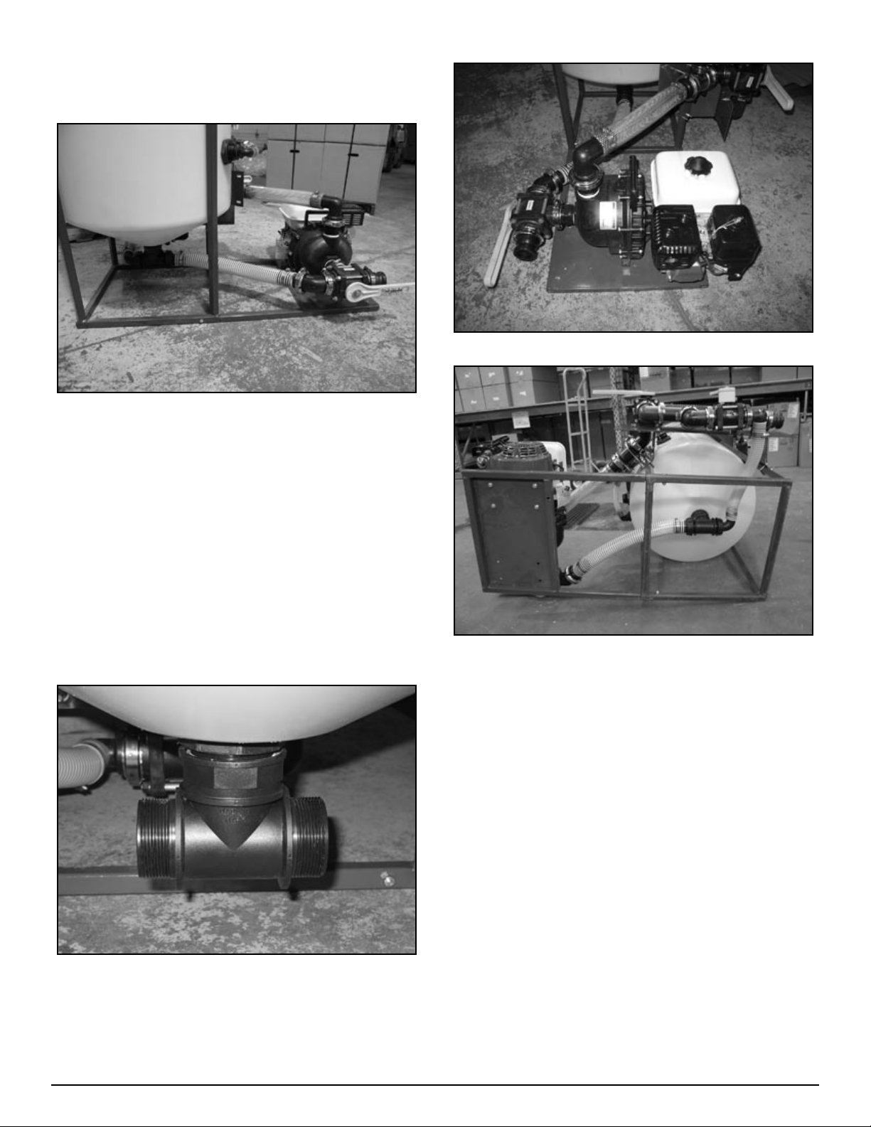
Step 5
Pump bracket installation
Figure H2-4.18
Fit pump bracket into bottom of tank frame (see figure H2-
1.
4.18).
Use two 5/16” X 1 1/2’” bolts and two 5/16” locking nuts to
2.
secure bracket to frame.
Figure H2-4.20
Step 6
Pump and recirculation
package installation
Mount pump to pump bracket using four 5/16” X 1 ½”L
1.
bolts, four 5/16” locking nuts and eight flat washers.
Figure H2-4.21
Install fittings as shown in figure H2-4.20 and H2-4.21.
3.
If using a pump/motor combination different than shown in
4.
the above figures may require repositioning of the pump to
direct exhaust away from the tank. This may require drilling extra holes in plate.
Figure H2-4.19
Install 2” Tee (10-11100) to bottom of tank (use pipe seal-
2.
ant) see figure H2-4.19.
19Handler I, II & III Operator’s Manual - October 2008
Page 20
Handler III Assembly
Overview
Assembly of your Handler 3 (without pump) follows four basic
steps:
Rinse valve and agitation fitting assembly and installation.
1.
Venturi bracket and plate installation.
2.
Three way valve support bracket installation.
3.
Venturi package assembly and installation.
4.
If you have purchased a Handler 3 with a pump or recirculation
package then there are two additional steps:
Pump bracket installation.
1.
Pump and recirculation package installation.
2.
Step 1
Rinse valve/agitation fitting assembly and
installation
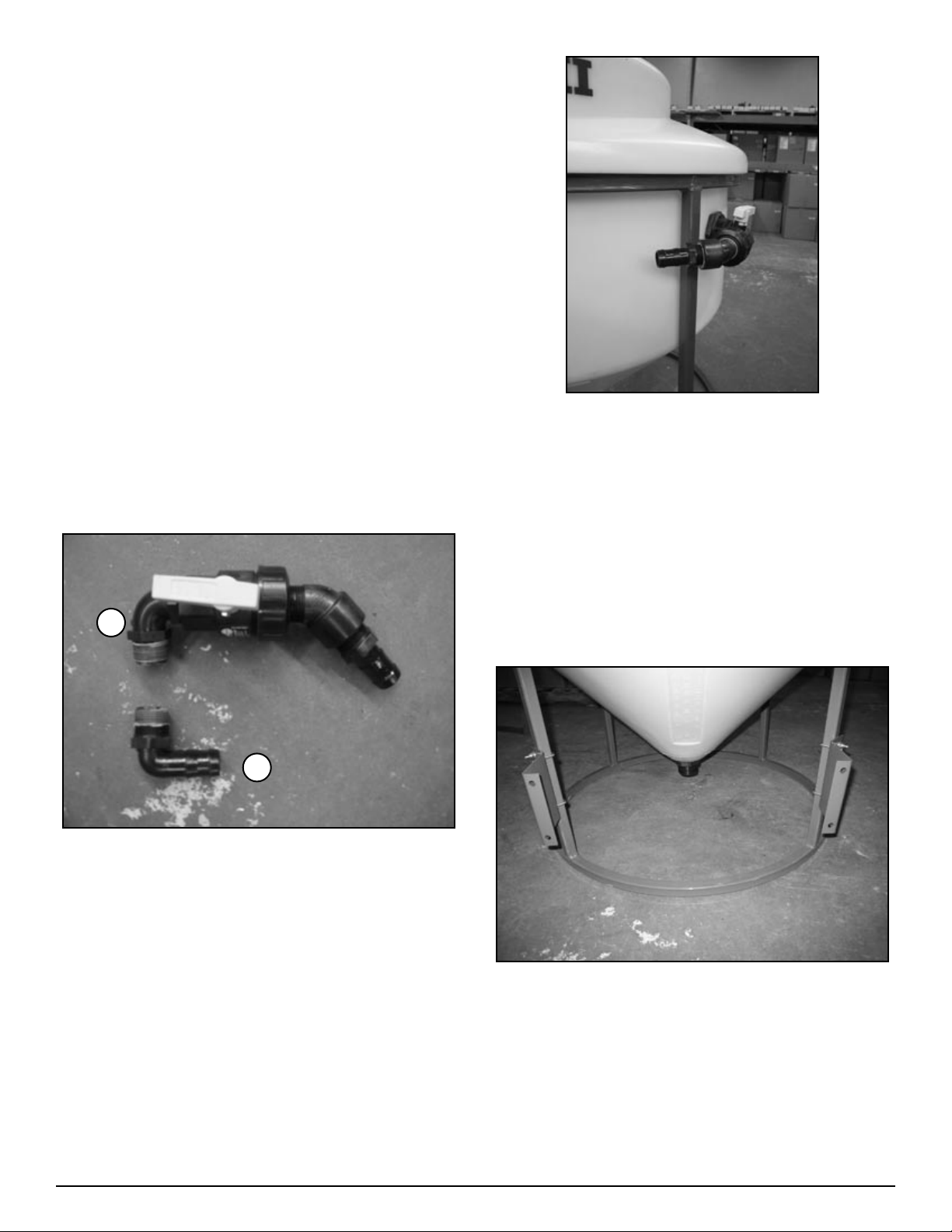
Figure H3-4.3
Install 1” street elbow 45 degree (25-SL100-45) into union
2.
side of ball valve.
Install 1” MPT X 1” Hose Barb (25-HB100) onto end of
3.
street elbow.
Attach the above assembly to 1” bulkhead on right side of
4.
tank (see figure H3-4.3).
B
A
Figure H3-4.1
Agitation Fitting Installation (figure H3-4.1, “A”).
Install 1” MPT X 1” HB 90 (25-HB100-90) on to 1” bulk-
1.
head on left side of tank. See figure H3-4.2. (Apply sealant
before assembling - see notes on page 37)
Rinse Valve Assembly (figure H3-4.1, “B”)
Install one 1” MPT X 1” MPT elbow (10-10980) on to 1”
1.
single union ball valve (25-UV100FP) on end opposite of
union. (Apply sealant before assembling - see notes on
page 37)
Step 2
Venturi bracket and plate installation
Figure H3-4.4
Mount angled frame brackets (86-HAFB) to frame as shown
1.
in figure H3-4.4. Use two 1” U-bolts (67-UB025-100) per
bracket. Bottom of bracket should be 7” from bottom of
frame. NOTE: Tighten only enough to prevent slipping.
20 Handler I, II & III Operator’s Manual - October 2008
Page 21
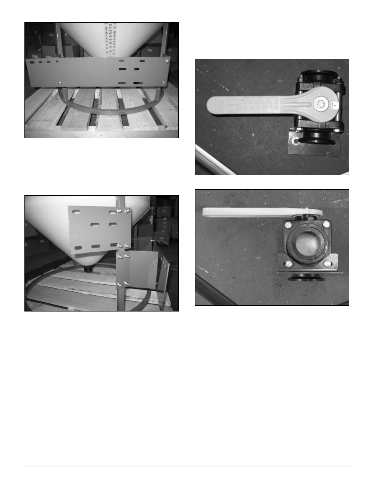
Figure H3-4.5
Mount venturi mounting plate (86-HVMP) on to angled
2.
frame brackets as shown in figure H3-4.5. Use three 5/16” X
1” bolts (67-CSH5C516-1P) – two on right side and one on
left lower side. Do not tighten completely yet.
Step 3
Three way valve support bracket
installation
Figure H3-4.32
Figure H3-4.6
Mount intake support plate (86-HISP) to frame as shown in
3.
figure H3-4.6. Use two 1” U-bolts (67-UB025-100), four ¼”
washers and four ¼” locking nuts. Do not tighten completely yet.
Go to next step (Three way valve support bracket installa-
4.
tion).
Figure H3-4.33
If two inch system install 2” three way valve support bracket
1.
(86-VASB2) on to three way valve as shown in Figure
H3-4.32 and H3-4.33 NOTE: handle operation should have
closed position to left when looking at front of valve.
21Handler I, II & III Operator’s Manual - October 2008
Page 22
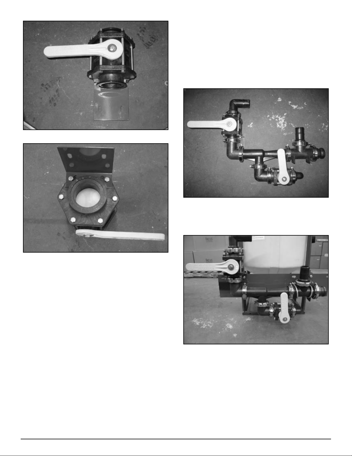
Figure H3-4.34
(intake).
Venturi comes with nozzle insert, will not run without.
•
Do not install 2” bypass hose (54-79250) until last.
•
Warm hoses before installing – use heat gun or pail of hot
•
water.
Lubricate hose barbs with liquid dish soap or silicone based
•
lubricant to make installation easier.
Assemble and install 1” fittings last.
•
Figure H3-4.35
If three inch system install 3” three way valve support
2.
bracket (86-VASB3) on to three way valve as shown in Figures H3-4.34 and H3-4.35 NOTE: handle operation should
have closed position to left when looking at front of valve.
Go to next step (Venturi package assembly and installation).
3.
Step 4
2” Venturi package assembly and
installation
Hints:
Lay all parts out first.
•
Open FC200 , FC220 and FC300 clamps slightly larger to
•
make assembly easier.
Open FC100 clamps completely to make assembly easier.
•
Part Number 25-M220CPG90 has long and short side. At-
•
tach short side to venturi and long side to 3 way ball valve
(25-MV220BL) as shown in figure H3-4.7
Start assembly at discharge end and work towards other end
•
Figure H3-4.8
Assemble manifold venturi package as shown in figure H3-
1.
4.8. Do not tighten completely yet.
Figure H3-4.9
Install partial assembly on to venturi mounting plate as
2.
shown in figure H3-4.9. Use two 5/16” X 1” bolts. Do not
tighten completely yet.
Install two 2 ½” U-bolts (67-UB038-250) to hold assembly
3.
to plate. Do not tighten completely yet.
22 Handler I, II & III Operator’s Manual - October 2008
Page 23
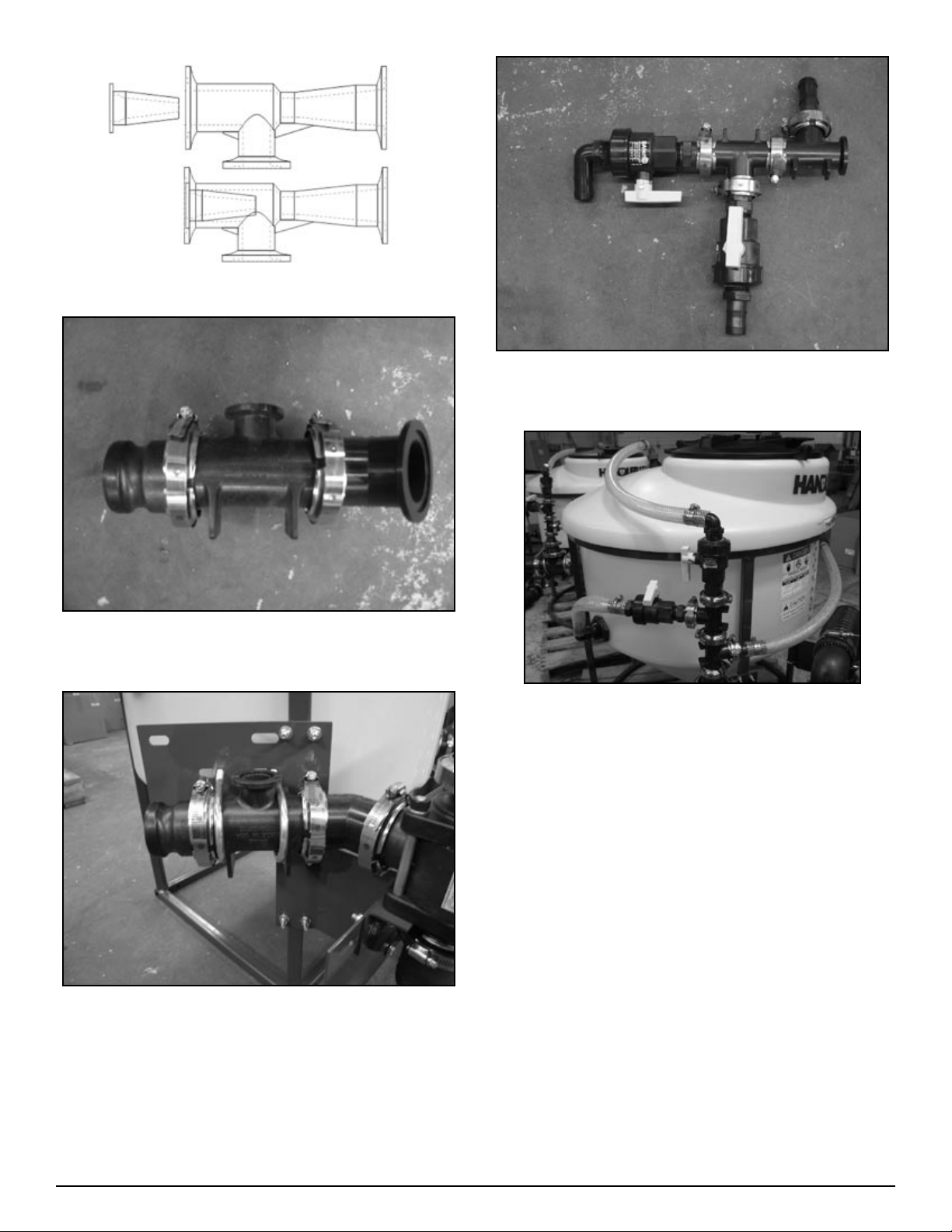
Venturi Nozzle Placement
Figure H3-4.10
Assemble remaining 2” fittings as shown in figure H3-4.10.
4.
Figure H3-4.13
Assemble 1” fittings as shown in figure H3-4.13.
7.
Figure H3-4.14
Install 1” fitting assembly as shown in figure H3-4.14. Do
8.
not tighten completely yet.
Tighten flange clamps on 2” fittings.
9.
Tighten U-bolts.
10.
Tighten remaining bolts.
11.
Align 1” fittings and tighten flange clamps.
12.
Figure H3-4.11
Mount second assembly to first as shown in figure H3-4.11
5.
(use 25-FC220 clamp and 25-200G gasket). Do not tighten
completely yet.
Install 2 ½ “ U-bolts (67-UB038-250) to hold second as-
6.
sembly to intake support plate. See figure H3-4.11. Do not
tighten completely yet.
23Handler I, II & III Operator’s Manual - October 2008
Page 24
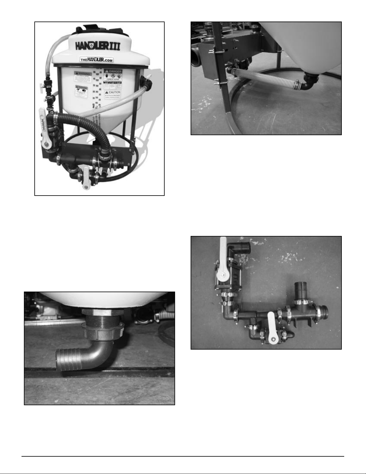
Figure H3-4.15
Figure H3-4.17
Measure, cut, and install 1 ½” PVC suction hose (54-79050)
16.
that goes between tank and venturi valve. Secure with
clamps (53-75624). See figure H3-4.17
3” Venturi package assembly and
installation
Install 2” bypass hose (54-79250) and secure with two
13.
clamps (53-75632) per end as in figure H3-4.15.
Hint: Install hose at bottom end and ensure proper length.
Heat other end and install hose barb. Attach hose barb to
assembly.
Measure, cut and install 1” clear braided hose (54-79210)
14.
for agitation and jug rinse lines. Secure with clamps (53-
75612).
Hints: see hints in 2” venturi package assembly and installation
instructions.
Figure H3-4.18
Assemble manifold venturi package as shown in figure H3-
1.
4.18. Do not tighten completely yet.
Figure H3-4.16
Install 2”FPT X 1 ½” hose barb 90 degree fitting on to bot-
15.
tom of tank, see figure H3-4.16
24 Handler I, II & III Operator’s Manual - October 2008
Page 25
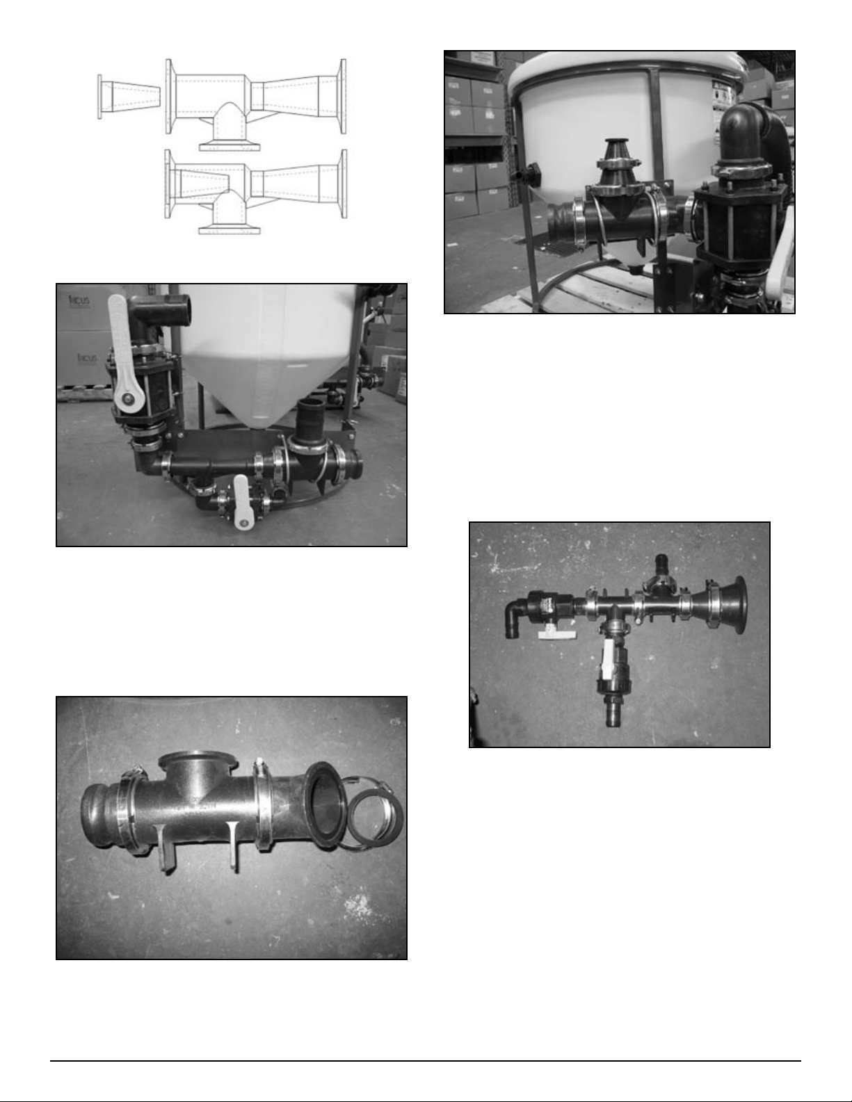
Venturi Nozzle Placement
Figure H3-4.19
Install partial assembly on to venturi mounting plate as
2.
shown in figure H3-4.19. Use two 3/8” X 1” bolts. Do not
tighten completely yet.
Install two 4” U-bolts (67-UB038-400) to hold assembly to
3.
plate. Do not tighten completely yet.
Figure H3-4.21
Assemble remaining 3” fittings as shown in figure H3-4.20
4.
.
Mount second assembly to first as shown in figure H3-4.21
5.
(use 25-FC300 clamp and 25-300G gasket). Do not tighten
completely yet.
Install 4 “ U-bolts (67-UB038-400) to hold second assembly
6.
to intake support plate. See figure H3-4.21 . Do not tighten
completely yet.
Figure H3-4.20
Figure H3-4.22
Assemble 1” fittings as shown in figure H3-4.22.
7.
25Handler I, II & III Operator’s Manual - October 2008
Page 26
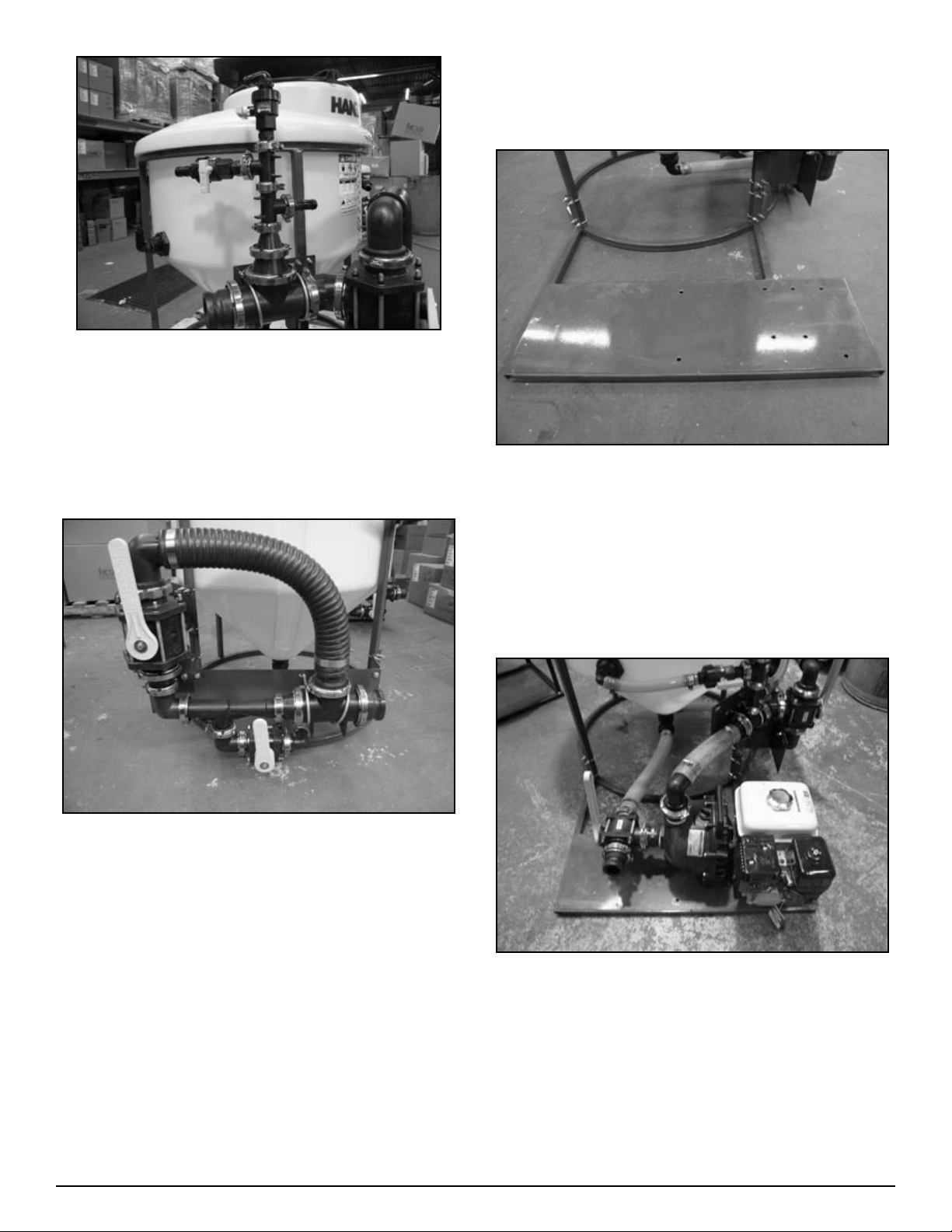
Figure H3-4.23
Install 1” fitting assembly as shown in figure H3-4.23 . Do
8.
not tighten completely yet.
Tighten flange clamps on 3” fittings.
9.
Tighten U-bolts.
10.
Tighten remaining bolts.
11.
Align 1” fittings and tighten flange clamps.
12.
Step 5
Pump bracket installation (all Handler III
models)
Figure H3-4.25
Install pump bracket into bottom of tank frame using four 1”
1.
U-bolts (67-UB025-100), see figure H3-4.25.
Figure H3-4.24
Install 3” bypass hose (54-79350) and secure with clamps
13.
(25-TC343) see Figure H3-4.24.
Hint: Install hose at bottom end and ensure proper length.
Heat other end and install hose barb. Attach hose barb to
assembly.
Measure, cut and install 1” clear braided hose (54-79210)
14.
for agitation , jug rinse and “Rotaflush” lines. Secure with
clamps (53-75612).
Install 2”FPT X 1 ½” Hosebarb 90 degree fitting on to bot-
15.
tom of tank, see figure H3-4.16.
Measure, cut, and install 1 ½” PVC suction hose (54-79050)
16.
that goes between tank and venturi valve. Secure with
clamps (53-75624). See figure H3-4.17.
Step 6
Two inch pump and recirculation package
installation
Figure H3-4.26
Mount pump to pump bracket using four 5/16’ X 1 ½”L
1.
bolts. See figure H3-4.26
26 Handler I, II & III Operator’s Manual - October 2008
Page 27
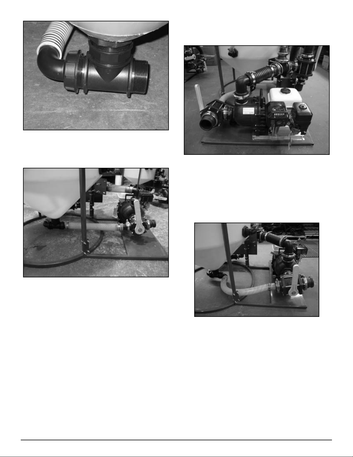
Figure H3-4.27
Install 2” Tee (10-11100) to bottom of tank (use sealant),
2.
see figure H3-4.27
Three inch pump and recirculation
package installation
Figure H3-4.29
Mount pump to “Z” rails using four 5/16’ X 1 ½” bolts.
1.
Mount pump to pump bracket using four 5/16’ X 3/4” bolts.
2.
See figure H3-4.29
Install 2” Tee (10-11100) to bottom of tank (use sealant),
3.
see figure H3-4.27
Figure H3-4.28
Install fittings as shown in figure H3-4.28.
3.
If using a pump/motor combination different than shown in
4.
figure H3-4.26 may require repositioning of the pump to direct exhaust away from the tank. This may require drilling
extra holes in plate.
Figure H3-4.30
Install fittings as shown in figure H3-4.30.
4.
If using a pump/motor combination different than shown in
5.
figure H3-4.29 may require repositioning of the pump to direct exhaust away from the tank. This may require drilling
extra holes in plate.
27Handler I, II & III Operator’s Manual - October 2008
Page 28

Operation
To the new operator or owner
It is the responsibiity of the owner or operator to read and understand this manual, the sprayer manual and the chemical container
label before starting. Follow all safety instructions exactly.
Safety is everyone’s business. By following recommended procedures, a safe working environment is provided for the operator, bystanders and the environment.
Many features incorporated into this equipment are the result
of suggestions made by customers like you. Read the manual
carefully to learn how to operate the machine safely, and how to
set it to provide maximum efficiency. By following the operating
instructions in conjunction with a good maintenance program,
your Handler will provide many years of trouble-free service.
How the System Works
Liquid product in containers
A sharp point and 4 blades are located inside the Handler tank to
puncture and split open the bottom of a container. As the bottom
of the container opens, fresh water is allowed to flow into the
container for rinsing.
Fresh water enters the bottom of the container from a line
through the side of the eductor tank. Valves in the plumbing control the removal of the contents of the tank and allow fresh water
to enter for rinsing the unit.
Mixing and removal of chemical from the Handler unit is accomplished using a venturi valve system.
Liquid bulk product
Operating Safety
Warning
Read and understand the Operator’s Manual and all
•
safety signs before operating, maintaining, adjusting or
unplugging the Handler.
Read chemical manufactures’ warnings, instructions
•
and procedures before starting and follow them exactly.
Do not put hands into the Handler when adding product.
•
Wear safety goggles, rubber gloves and protective cloth-
•
ing whenever working with the Handler or on a machine
or a component containing toxic product.
Keep all shields and guards in place when operating.
•
Clear the area of all bystanders, especially children,
•
before starting.
Review safety instructions annually.
•
Each Handler tank is calibrated with high visibility, accurate markings to easily measure product pumped from a bulk
container. The bulk product is pumped into the Handler tank
through the lid, or through a special closed fitting adapted to the
Handler’s lid.
Dry product
Each Handler tank comes with an agitation nozzle. When combined with the venturi or the recirculation package, the user can
easily mix dry product.
The venturi
The venturi system operates on principles of suction. As water
is being pumped through the venturi, a suction is created which
draws the tanks contents from the tank, simultaneously providing fresh water to rinse the container.
With the venturi system only one pump is required to operate the
system. The pump is always placed before the venturi and the
Handler.
Break In
Although there are no operational restrictions on the Handler
when used for the first time, it is recommended that the following mechanical items be checked:
28 Handler I, II & III Operator’s Manual - October 2008
Page 29

Functional Check
Operation
After the Handler has been installed, a complete functional
check should be done to verify that the plumbing has been properly connected and there are no leaks. Before adding product to
the system, run the system as if adding products during operation, but using only water. Open and close each valve to simulate
the complete operation of chemical removing and container
rinsing.
NOTE: Place a used, clean container in the handler to direct the
stream of water back into the tank.
Check all fittings and connections for leaks. Stop all leaks by
tightening fittings/clamps or disassembling and applying a thread
sealant to the threads. Do not use products unless all leaks have
been stopped.
After adding 5 and 50 containers of
products
Re-torque all mounting fasteners
Check plumbing for leaks. Stop all leaks by tightening fittings or
disassembling and applying a thread sealant to the threads.
The Handler can be adapted for use with any existing sprayer or
water supply vehicle. It may be used for adding liquid, dry, or
packaged products. The capability of your water supply source
and the type of valve system you have chosen to purchase with
your Handler will determine the installation configuration and
the operating procedures. Carefully review the section that applies to your particular system.
Caution
Wear appropriate personal protective gear whenever
•
working with the Handler or around toxic chemicals.
Read and follow warnings and instructions on chemical
•
container label.
Do not place hands into Handler tank at any time.
•
Review Sprayer Manual before starting.
•
Pre-operation Checklist
Efficient and safe operation of the Handler requires that each
operator reads and understands the operating procedures and all
related safety precautions outlined in this section. A pre-operational checklist is provided for the operator. It is important for
both personal safety and maintaining the good mechanical condition of the Handler that this checklist be followed.
Before using the Handler and each time thereafter the following
areas should be checked off:
Check that your personal protective gear is in good condi-
•
tion.
Review the warnings and instructions on the chemical con-
•
tainer label.
Check the plumbing for leaks. Repair all leaks before start-
•
ing.
Review and follow the Pre-Operation checklist for the
•
sprayer.
Check pump engine for oil and top up if necessary.
•
29Handler I, II & III Operator’s Manual - October 2008
Page 30
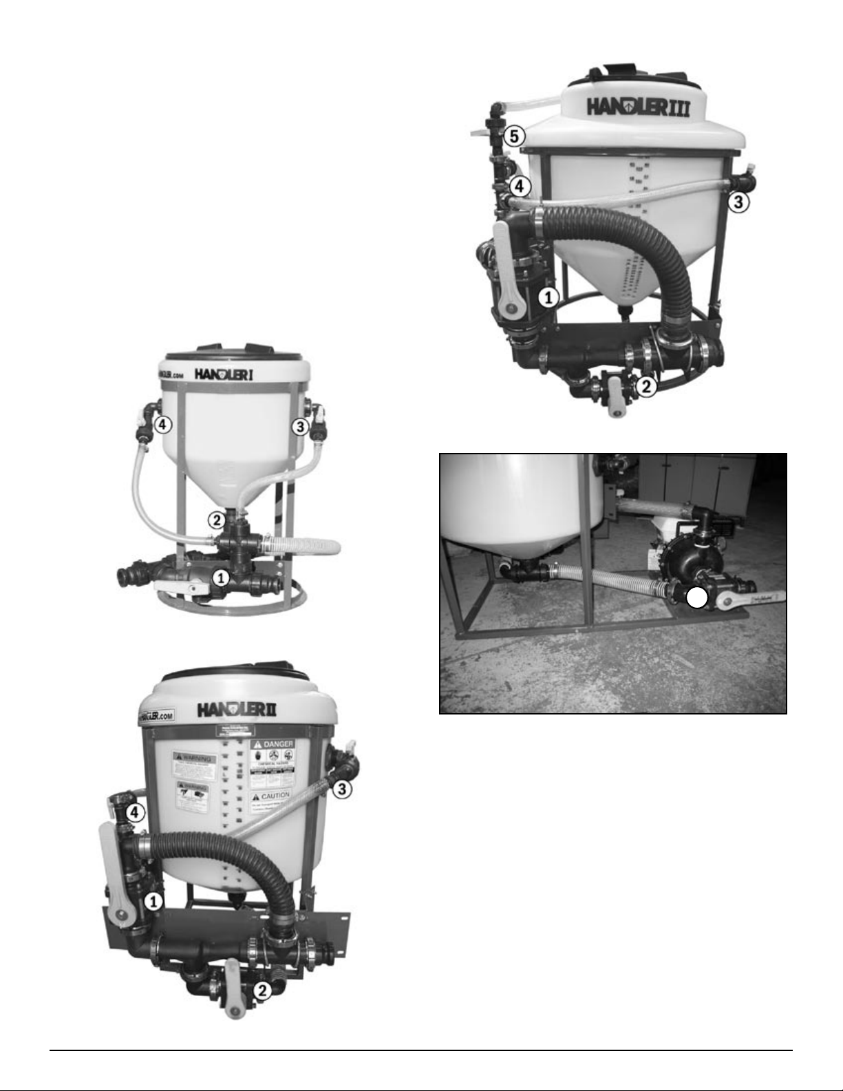
Valve Descriptions
In the operation instructions valves are referred to their purpose in the system. Using the images below, find the model of
Handler that you have purchased and familiarize yourself with
the valves and their names prior to moving on to the operation
instructions.
Main valve (3-way valve)
1.
Venturi valve
2.
Container rinse valve (knife valve)
3.
Agitation valve
4.
Rotaflush valve (Handler III only)
5.
Pump suction valve (Optional - Handler II & III only)
6.
Handler III valves
Handler I valves
6
Optional pump suction valve - Handler II or III
Handler II valves
30 Handler I, II & III Operator’s Manual - October 2008
Page 31
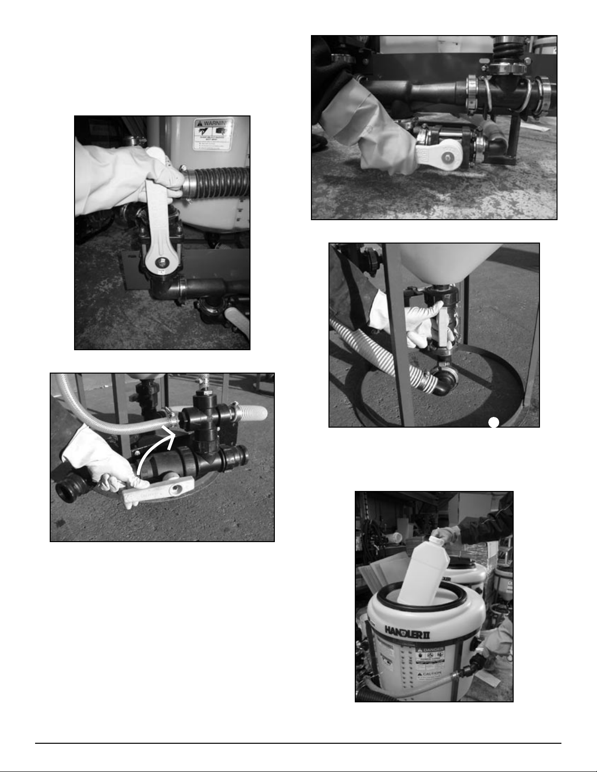
Emptying Liquid Containers
Close all valves and open lid.
1.
With all valves closed, start nurse pump to draw fresh water
2.
from water supply tank.
Figure H2-5.2 Handler II or III
Figure H2-5.1 Handler II or III
Figure H1-5.1 Handler I
Move handle on Main Valve to venturi position to allow
3.
water to flow through venturi, (See Figure H1-5.1 and H2-
5.1)
6
Figure H2-5.2 Handler I
Open Venturi Valve to allow suction from Handler tank,
4.
(See Figure H2-5.2 and H1-5.2)
Figure H2-5.3
31Handler I, II & III Operator’s Manual - October 2008
Page 32
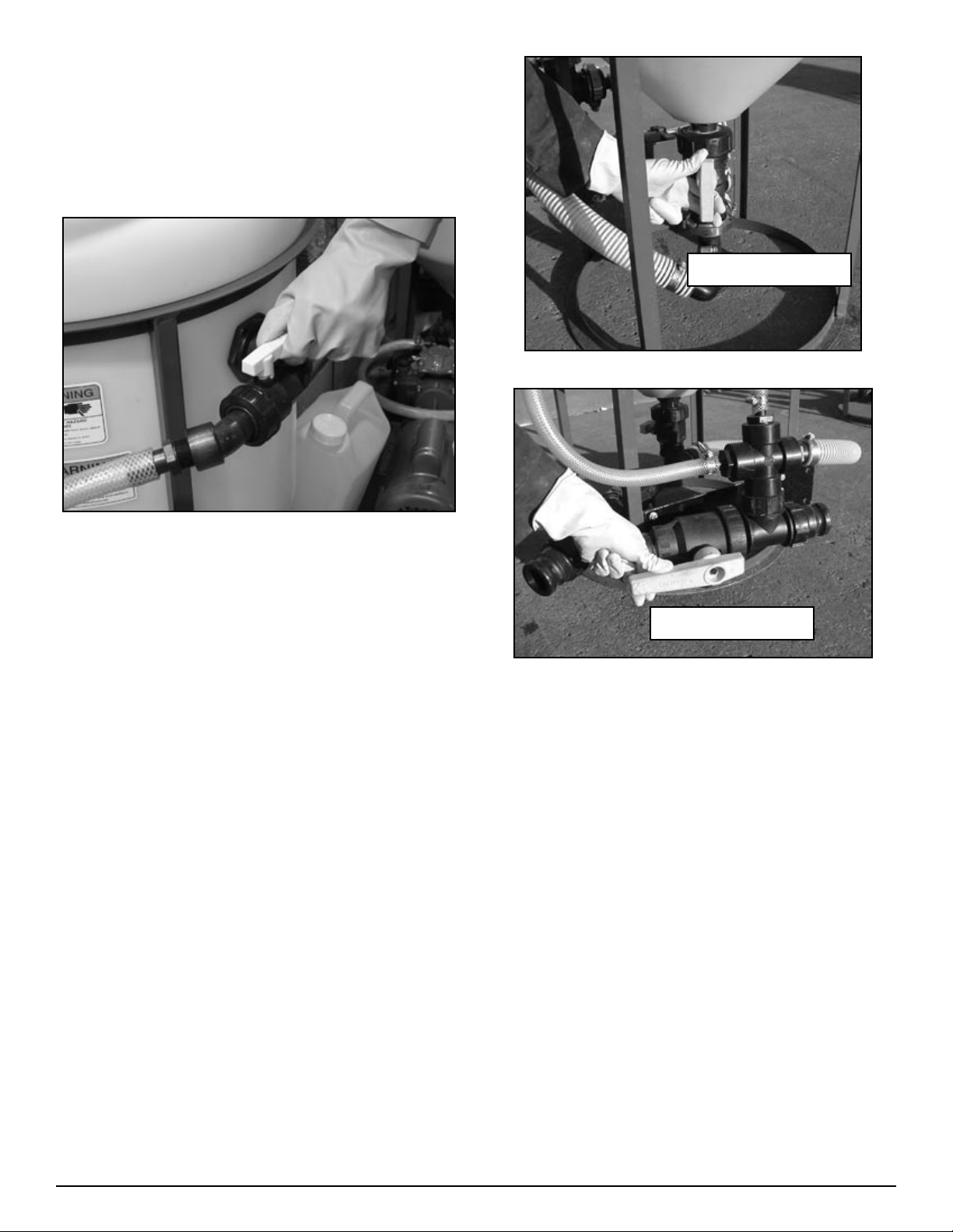
Plunge container into tank and puncture on knife. Push
5.
container down with consistent, even force to cut the bottom
and then allow to drain. (See Figure H2-5.3)
HINT: puncture to one side of bottom (stay away from
•
the centre as this is usually the thickest part of the
container) and make sure knife cuts up side wall of
container.
Shown in open position
Figure H1-5.7a
Figure H2-5.7
Hold punctured container on knife and open Container
6.
Rinse Valve to rinse container, (See Figure H2-5.7) Repeat
until container is thoroughly rinsed. Then close Container
Rinse Valve and remove container.
Repeat steps # 5 and #6 until all containers have been
7.
rinsed.
Tank Cleanout Instructions
Handler I Tank Cleanout
Replace lid and open Container Rinse Valve to rinse Han-
1.
dler tank. When rinsing is complete, close Container Rinse
Valve to stop water flow into Handler tank.
NOTE: rinse water is being continuously sent off to
•
sprayer as rinsing is occurring.
Shown in open position
Figure H1-5.7b
To fill the remainder of the sprayer tank, close Venturi
2.
Valve and open Main Valve. (See Fig H1-5.7a and H1-
5.7b). All valves, except Main Valve, should now be
closed. This terminates the water flowing to and from the
Handler tank allowing fresh water from the source tank to
bypass the venturi system and finish filling the sprayer tank.
When desired sprayer tank volume is achieved, close Main
3.
Valve.
32 Handler I, II & III Operator’s Manual - October 2008
Page 33
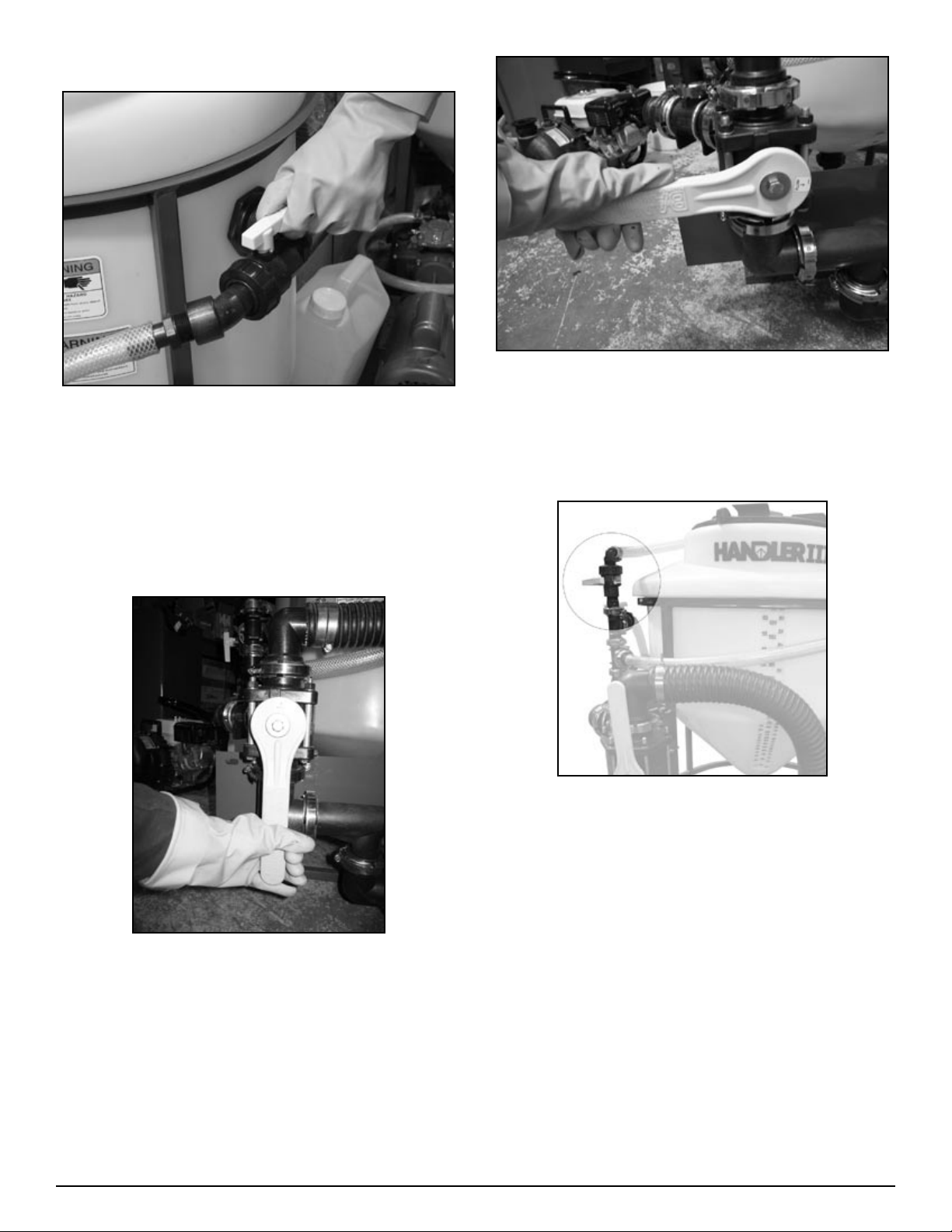
Handler II Tank Cleanout
Figure H2-5.5
Figure H2-5.7
Close lid and open Container Rinse Valve to rinse Handler
1.
Tank, (See Figure H2-5.7) When rinsing is complete, close
Container Rinse Valve to stop flow of water into Handler
tank.
NOTE: rinse water is being continuously sent off to sprayer
•
as rinsing is occurring.
Close Venturi Valve to stop suction from Handler tank.
2.
Figure H2-5.4
To fill remainder of the sprayer tank with fresh water, move
3.
handle on Main Valve to bypass position, (See Figure
H2-5.4) This terminates the flow of product/water from the
Handler tank, allowing fresh water from the source tank to
bypass the venturi system and finish filling the sprayer tank.
When desired sprayer tank volume is achieved, move handle
4.
on Main Valve to closed position, (See Figure H2-5.5)
Handler III Tank Cleanout
Figure H3-5.7
Close lid and open Rotaflush valve to rinse Handler Tank.
1.
When rinsing is complete, close Rotaflush Valve to stop
flow of water into Handler tank.
NOTE: rinse water is being continuously sent off to sprayer
•
as rinsing is occurring.
Close Venturi Valve to stop suction from Handler tank.
2.
To fill remainder of the sprayer tank with fresh water, move
3.
handle on Main Valve to bypass position, (See Figure H2-
5.4). This terminates the flow of product/water from the
Handler tank, allowing fresh water from the source tank to
bypass the venturi system and finish filling the sprayer tank.
When desired sprayer tank volume is achieved, move handle
4.
on Main Valve to closed position, (See Figure H2-5.5).
33Handler I, II & III Operator’s Manual - October 2008
Page 34
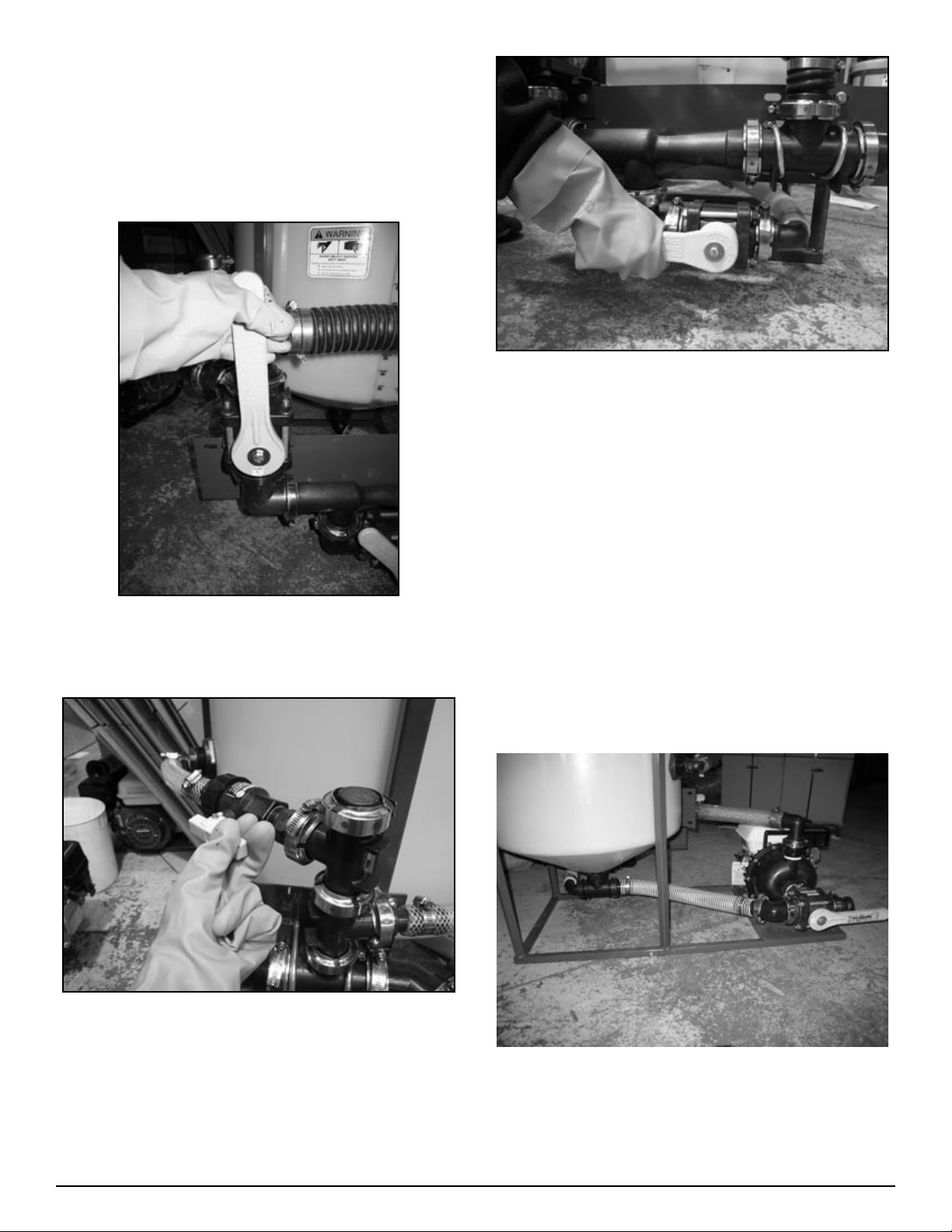
Dry Product: (recirculation
not available/not used)
Close all valves and open lid.
1.
With all valves closed, start nurse pump to draw fresh water
2.
from water supply tank.
Figure H2-5.2
Open Venturi Valve to allow suction from Handler tank,
5.
(See Figure H2-5.2)
Pour powder or dry product slowly into tank and stream of
6.
water discharging from agitation jet. Dry product will mix
with water swirling in bottom of Handler tank and then will
be drawn away by venturi. Be careful not to pour too much
product at any one time as this may cause plugging of the
anti-vortex fitting in tank bottom.
See Tank Cleanout instructions above
•
Figure H2-5.1
Move handle on Main Valve from closed position to venturi
3.
position, (See Figure H2-5.1)
Figure H2-5.6
Open Agitation Valve to allow water to flow from agitation
4.
jet, (See Figure H2-5.6)
Batch mix/Premix liquids,
powders and granules
(recirculation/pump package required
- Handler II and III only)
Close all valves and open lid on Handler.
1.
Figure H2-5.8
Position handle on Pump Suction Valve to draw fresh water,
2.
start nurse pump to draw fresh water from water supply
tank, (See Figure H2-5.8)
34 Handler I, II & III Operator’s Manual - October 2008
Page 35
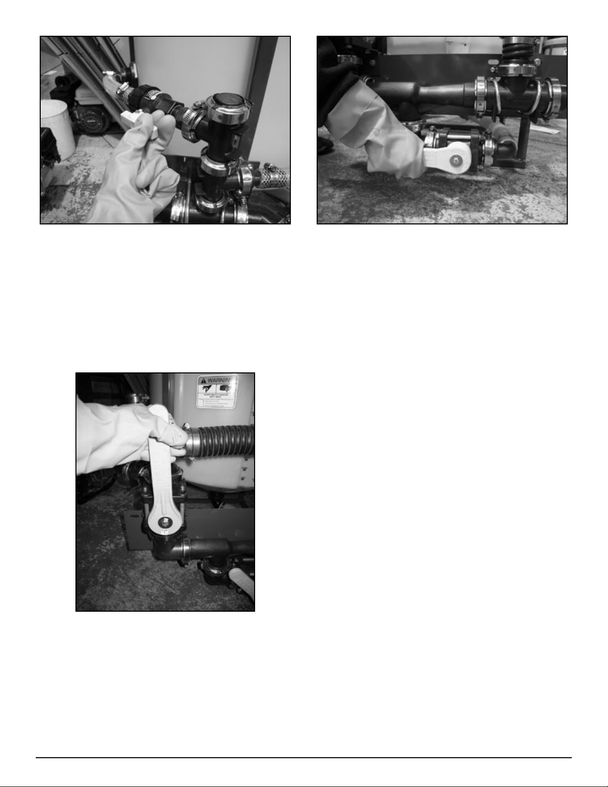
Figure H2-5.6
Open Agitation Valve and fill tank to desired level then
3.
close Agitation Valve. (See Figure H2-5.6)
Turn handle on Pump Suction Valve so pump is drawing
4.
from Handler tank (recirculating).
Open Agitation Valve to complete recirculation flow. (See
5.
Figure H2-5.6)
NOTE: Rate of flow can be controlled with Agitation
•
Valve and/or adjusting pump motor speed.
Figure H2-5.2
If venturi delivery is preferred then close Agitation Valve,
6.
then turn Pump Suction Valve (See Figure H2-5.8) to draw
fresh water and then turn Main Valve to venturi position.
(See Figure H2-5.2)
See Tank Cleanout instructions above
•
Figure H2-5.1
Add product to water in tank and agitate for as long as
6.
required.
Close Agitation Valve (See Figure H2-5.6) and position the
7.
Main Valve to bypass (This will use the pump to deliver
mixture to sprayer). (See Figure H2-5.1)
35Handler I, II & III Operator’s Manual - October 2008
Page 36

Troubleshooting
The Focus Industries Inc. Handler is a simple eduction system
that employs a venturi suction system to place product into
your sprayer tank. It is a convenient and reliable system which
requires minimal maintenance.
Problem Cause Solution
Venturi won’t suck Improper installation of venturi Check to make sure the venturi has been installed in the
Improper line size Check to make sure the discharge line is large enough to ac-
Obstructions in the lines Check to see if there are obstructions in the line after the
Venturi will suck, but not when
the lines are hooked to the sprayer, or your sprayer fills up before
all the product can be sucked from
the Handler.
Jug won’t puncture properly Dull blade Resharpen the knife assembly by removing the assembly
Jug won’t puncture properly, jug
won’t empty
Improper fittings If the venturi is sucking properly, check all fittings to make
Filter One of the most common causes of back pressure and
Your sprayer inlet is 1 1/2” or
your tank is smaller than 500
gallons
Extra thick jug Some of the jugs on the market are extra thick. We rec-
The following troubleshooting section lists many of the problems you may encounter. It defines the possible causes and
presents solutions to the problems. If you have a different problem, even after having read through this troubleshooting section,
please call you local Handler dealer or the factory. Before you
call, please have this Operator’s manual as well as the model
type and operating system you have purchased available for
reference.
proper direction and ensure that the nozzle of the venturi is
in place.
commodate the flow of the mixture. Discharge line should
be no smaller than the size of the fittings that make up the
venturi package (2” or 3” depending on the model).
venturi. This can be done by running a hose directly from
the venturi to the top of the sprayer tank, bypassing all of
the sprayer plumbing.
sure they are not smaller than the hose size being used.
Note that tees and elbows will add back pressure and reduce
the performance of the venturi, so avoid or reduce the use of
these where possible.
reduced venturi performance is the presence of filters in the
fill line at the sprayer. If you insist on having a filter at the
inlet to your sprayer be aware that it will effect the performance of your venturi.
Your Handler must be adapted to 1 1/2” fittings. The easiest way to do this is to change the camlock sizes of your
2” Handler to 1 1/2” using reducers and 1 1/2” camlocks.
Simply reducing your hose from 2” to 1 1/2” at the sprayer
will not work.
and hand sharpening with a file or grinder.
ommend puncturing the bottom of any jug off of the thick
reinforced seam. This is the weakest point on the container
and it cuts up the side of the container allowing for full
drainage. See image below for proper puncture location.
36 Handler I, II & III Operator’s Manual - October 2008
Page 37

Problem Cause Solution
Chemical is splashing Improper handling of jugs Apply constant, even pressure when puncturing the con-
tainer. Don’t force the jug onto the knife assembly.
Dull blade Resharpen the knife assembly by removing the assembly
and hand sharpening with a file or grinder.
Suction line is drawing air Incorrect valve settings Reduce suction from the Handler tank by partially closing
the suction valve. This will regulate the speed at which the
mixture is drawn from the Handler. Once all of the liquid
has been drawn from the tank, shut off the suction valve.
Pump is cavitating Incorrect valve settings Reduce suction from the Handler tank by partially closing
the suction valve. This will regulate the speed at which the
mixture is drawn from the Handler. Once all of the liquid
has been drawn from the tank, shut off the suction valve.
Clogged suction lines or venturi Granular product is insufficient-
ly dissolved
Threaded fittings leak Improper sealant usage It is important the manufacturers instructions for use are fol-
Hose is difficult to install Heat the hose in boiling water until soft. Slide on to hose
Tank calibration not accurate Tank is not level Level the system.
Fittings and line volumes not
accounted for
Inside of tank dirty Regular use See the section of this manual that covers cleaning the tank
Contamination in optional recirculation line
Improper rinsing/cleaning Add a second ball valve on the bottom of the tank to com-
Force water back into the venturi by opening the bypass
valve. This allows water to back up into the Handler tank
and dislodge any obstructions.
lowed. As a reminder:
Store and apply between 20 F and 140 F to clear ta-
1.
pered threads.
For pipe diameters up to 1 1/4”, apply thick even coat
2.
to male threads only. For large sizes apply to both male
and female threads.
For up to 2” pipe, tighten up to 3 full turns past hand
3.
tight and for larger sizes up to 2 full turns. Additional
tightening may be required but do not overtorque to
stretched condition.
Cure time may vary with application and service condi-
4.
tions - normally 24 hours.
barb fitting. If necessary, hose lubricants and silicone are
available and can be used if compatible.
The tank calibration marks indicate the volume of the tank,
but do not take into account added volume in the lines and
fittings. Pre-calibrate the volume of your lines and fittings
to get more accurate readings.
pletely isolate the line returning to the pump.
37Handler I, II & III Operator’s Manual - October 2008
Page 38
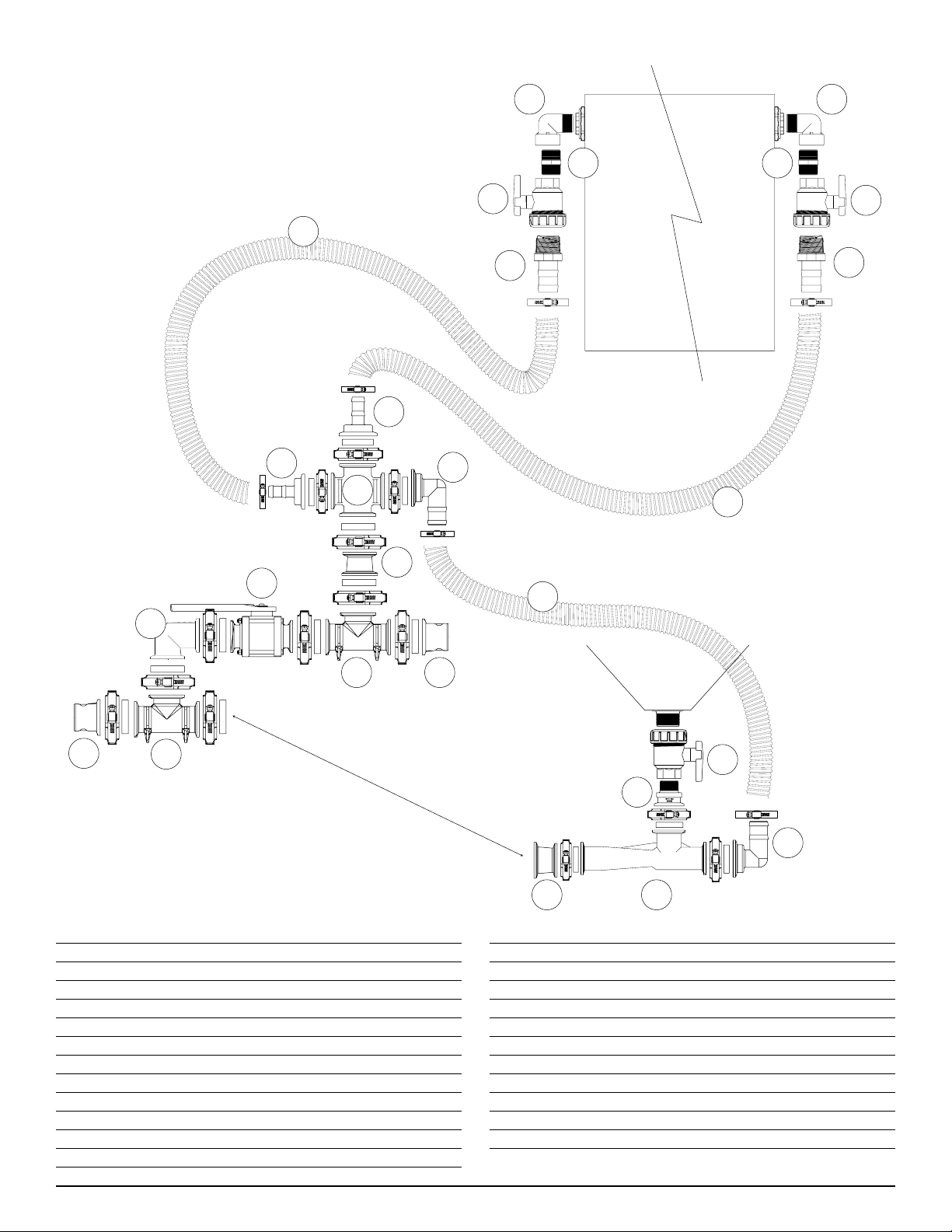
Handler Tank
Handler Tank
Agitation
Line
Knife/Rinse
Line
Venturi Line
1
1
2 2
3
3
4
4
21
21
23
15
15
14
8
9
1110
13
12
10
11
9 7
8
6
5
2” Handler I Manifold Venturi
Package Breakdown
(2” Fittings and 1 ½” Venturi)
# Part No. Description Qty
1 25-SL075-90 3/4” Street Elbow 2
2 25-NIP075-SH 3/4” Short Nipple 2
3 25-UV075FP 3/4” Single Union Ball Valve 2
4 25-HB075-100 3/4” MPT X 1” HB Adapter 2
5 25-UV125FP 1 1/4” Single Union Ball Valve 1
6 25-M200125MPT 2” SP Flange X 1 1/4” MPT 1
7 85-HV150FLA 1 1/2” Venturi, Flanged 1
8 25-M200150BRB90 2” SP Flange X 1 1/2” HB 90 2
9 25-M220200CPG 2” FP X 2” SP Flanged Coupler 1
10 25-M220TEE 2” FP Flanged Tee 2
11 25-M220A 2” FP Flange X 2” Male Camlock 2
12 25-M220CPG90 2” FP Flanged Coupler 90 Degree 1
# Part No. Description Qty
13 25-MV220CF 2” FP Flanged Ball Valve 1
14 25-M200CR 2” SP Flanged Cross 1
15 25-M200100BRB 2” SP Flange X 1” Hose Barb 2
- 25-FC220 220 Series Flange Clamp 7
- 25-FC200 200 Series Flange Clamp 7
- 25-150G EPDM Gasket for 200 Series 7
- 25-200G EPDM Gasket for 220 Series 7
- 53-75612 MC12SS Hose Clamp 4
21 54-79210 1” Clear Braided PVC Hose 3.0 ft
- 53-75624 MC24SS Hose Clamp 2
23 54-79050 1 1/2” PVC Suction Hose 1.5 ft
38 Handler I, II & III Operator’s Manual - October 2008
Page 39
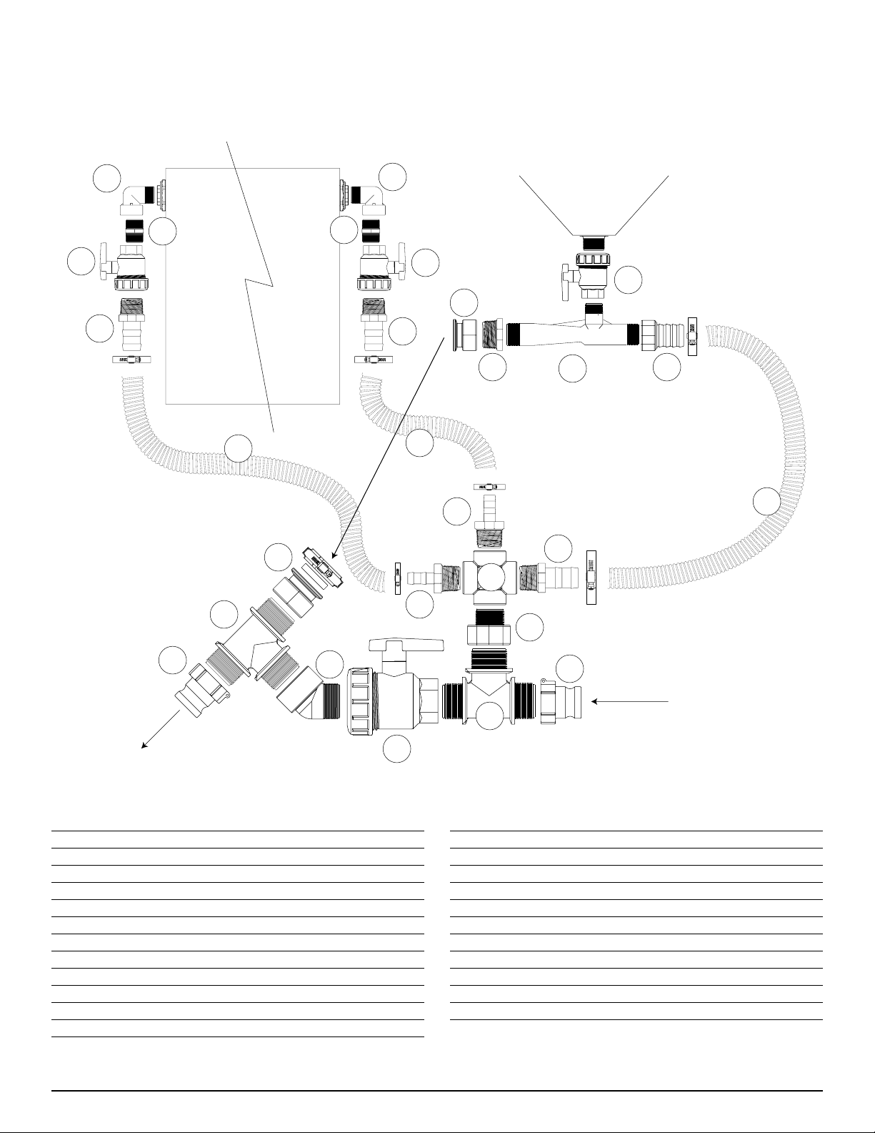
Handler Tank
Handler Tank
Agitation
Line
Knife/Rinse
Line
Venturi Line
1
4
1
4
2
2
3
3
6
6
12
9
8
18
7
22
21
2
20
20
16
11
13
15
14
13
12
11
Handler I Threaded Venturi Package Breakdown
(2” Fittings and 1 ½” Venturi)
# Part No. Description Qty
1 25-SL075-90 3/4” MPT x FPT Street Elbow 2
2 10-10190 3/4” Single Union Ball Valve 2
3 30-60830P 3/4” MPT x HB Adapter 2
4 30-61580P 3/4” MPT Short Nipple 2
- 53-75610 MC10SS Hose Clamp 4
6 54-79200 3/4” Clear Braided Hose 3.5 ft
7 10-10210 1 1/4” Single Union Ball Valve 1
8 85-HV150 1 1/2” Venturi, Threaded 1
9 30-61810P 2” MPT x 1 1/2” FPT Bushing 1
10 25-FC200 200 Series Flange Clamp 1
11 25-200A 2” FPT x 2” Male Camlock 2
12 25-M200FPT 2” Flange x 2” FPT Manifold Fit. 2
# Part No. Description Qty
13 10-11105 2” MPT Poly Tee 2
14 25-SL200-45 2” MPT x FPT Stree Elbow 1
15 10-10230 2” Single Union Ball Valve 1
16 49-40013 2” FPT x 1 1/4” MPT Adapter 1
17 25-150G EPD Gasket for 200 Series 1
18 10-10300 1 1/2” FPT x HB Adapter 1
19 25-CR125 1 1/4” 4 Way Cross 1
20 25-HB125-075 1 1/4” x 3/4” HB Adapter 2
21 30-60940P 1 1/4” x 1 1/2” HB Adapter 1
22 54-79050 1 1/2” PVC suction hose 3.0 ft
23 53-75624 MC24SS hose clamp 2
39Handler I, II & III Operator’s Manual - October 2008
Page 40
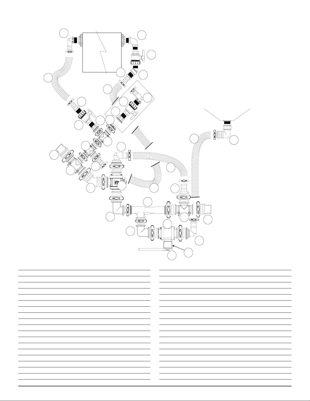
Handler III R
otaFlush Ki
t
Handler Tank
Handler Tank
Agitation
Line
Knife/Rinse
Line
Bypass Line
Venturi Suction Line
15
16
13
36
14
24
24
14
13
12
10
10
1
34
3
11
5
4
17
24
7
18
8
9
6
2
1
25
19
15
13
12
23
32
33
35
Note: Part quantities in the RotaFlush kit
are not included in the breakdown quantities
below.
2” Handler II & III Manifold
Venturi Package Breakdown
# Part No. Description Qty
1 25-M220A 2” FP Flange X 2” Male Adapter 2
2 25-M220TEE 2” FP Flanged Tee 2
3 25-M220CPG45 2” FP Flanged Coupler 45 1
4 25-MV220BL 2” FP Flanged Valve Bottom Load 1
5 25-M220BRB90 2” FP Flange X 2” HB 90 1
6 25-M220BRB 2” FP Flange X 2” HB 1
7 85-HV200FLA 2” Flanged Venturi 1
8 25-MV200CF 2” SP Flanged Valve 1
9 25-M200150BRB90 2” SP Flange X 1 1/2” HB 90 1
10 25-M100TEE 1” Flanged Tee 2
11 25-M100BRB 1” Flange X 1” Hose Barb 1
12 25-M100MPT 1” Flange X 1” MPT 1
13 25-UV100FP 1” Single Union Ball Valve 2
14 25-HB100 1” MPT X 1” HB 2
15 25-HB100-90 1” MPT X 1” HB 90 1
16 10-10980 1” MPT X 1” MPT Elbow 90 1
17 25-M220CPG90 2” FP Flanged Coupler 90 1
18 25-M200CPG90SH 2” SP Flanged Coupler 90 1
40 Handler I, II & III Operator’s Manual - October 2008
# Part No. Description Qty
19 10-10910 2” FPT X 1 1/2” HB 90 1
- 53-75624 MC24SS Hose Clamp 2
- 53-75612 MC12SS Hose Clamp 4
- 53-75632 MC32SS Hose Clamp 4
23 54-79250 2” Kanaflex EPDM Ribbed Hose 2 ft
24 54-79210 1” Clear Braided PVC Hose 3 ft
25 54-79050 1” PVC Suction Hose 1.5 ft
- 25-FC220 220 Series Screw Clamp 9
- 25-200G EPDM Gasket for 220 Series 9
- 25-FC200 200 Series Screw Clamp 3
- 25-150G EPDM Gasket for 200 Series 3
- 25-FC100 100 Series Screw Clamp 5
- 25-M100G EPDM Gasket for 100 Series 5
32 25-V20153138 Handle Offset for 25-MV200CF 1
33 67-CSHC14-2S1 2”L x 1/4” SS Nolt for Handle 1
34 25-M220100TEE 2” FP Flange X 1” Flange Tee 1
35 25-M100PLG 1” Flange Plug 1
36 25-SL100-45 1” Street Elbow 45 Degree 1
Page 41
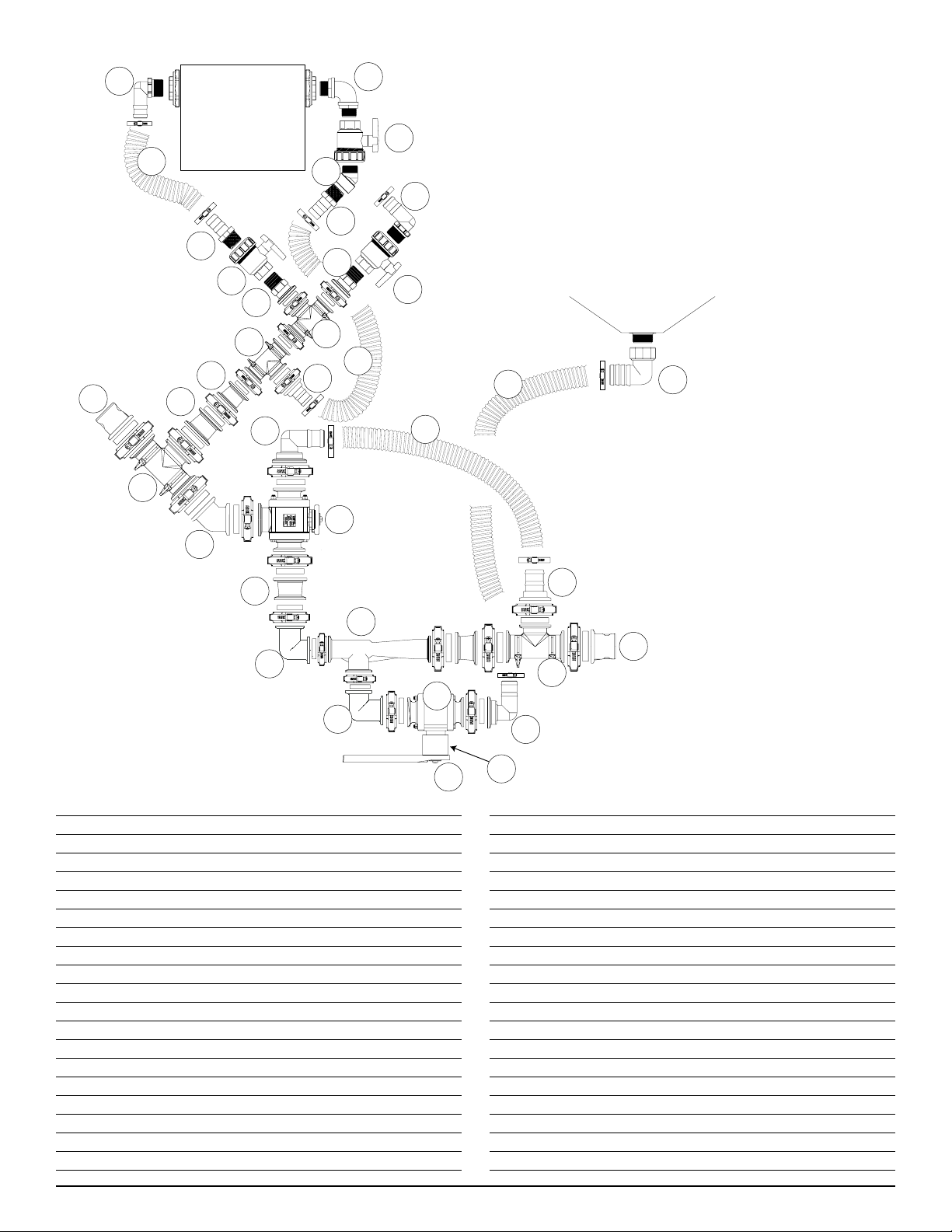
Handler Tank
Handler Tank
Agitation
Line
Venturi Suction Line
Knife/Rinse
Line
Bypass Line
19
20
17
21
18
36
19
17
22
35
34
1
2
6
12
11
10
7
9
8
4
3
5
2
1
8
13
14
15
16
17
18
36
14
16
37
38
3” Handler III Manifold
Venturi Package Breakdown
# Part No. Description Qty
1 25-M300A 3” FP Flange X 3” Male Adapter 2
2 25-M300TEE 3” FP Flanged Tee 2
3 25-M300CPG45 3” FP Flanged Coupler 45 1
4 25-MV300BL 3” FP Flanged Valve bottom load 1
5 25-M300BRB90 3” FP Flange X 3” HB 90 1
6 25-M300BRB 3” FP Flange X 3” HB 1
7 85-HV200FLA 2” Flanged Venturi 1
8 25-M300220CPG 3” Flange X 2” FP Flange Coupler 3
9 25-220CPG90 2” FP Flange Coupler 90 1
10 25-200CPG90SH 2” SP Flange Coupler Short 90 1
11 25-MV200CF 2” SP Flanged Valve 1
12 25-M200150BRB90 2” SP Flange X 1 1/2“ HB 90 1
13 25-M220100CPG 2” FP x 1” Flanged Coupler 1
14 25-TEE100 1” Flanged Tee 2
15 25-M100BRB 1” Flange X 1” HB 1
16 25-M100MPT 1” Flange X 1” MPT 2
17 25-UV100FP 1” Single Union Ball Valve 3
18 25-HB100 1” MPT X 1” HB 2
19 25-HB100-90 1” MPT X 1” HB 90 2
20 10-10980 1” MPT X 1” MPT 90 1
21 25-SL100-45 1” Street Elbow 45 1
# Part No. Description Qty
22 10-10910 2” FPT X 1 1/2” HB 90 1
- 53-75624 MC24SS Hose Clamp 2
- 25-TC343 TC343 SS Super T Hose Clamp 2
- 53-75612 MC12SS Hose Clamp 6
- 25-FC300 300 Series Clamp 9
- 25-300G EPDM Gasket for 300 Series 9
- 25-FC220 220 Series Clamp 4
- 25-200G EPDM Gasket for 220 Series 4
- 25-FC100 100 Series Clamp 5
- 25-M100G EPDM Gasket for 100 Series 5
- 25-FC200 200 Series Clamp 3
- 25-150G EPDM Gasket for 200 Series 3
34 54-79350 3” Kanaflex Ribbed EPDM Hose 2.5 ft
35 54-79050 1 1/2” PVC Suction Hose 1.5 ft
36 54-79210 1” Clear Braided PVC Hose 6 ft
37 25-V20153138 Handle Offset for 25-MV200CF 1
38 67-CSHC14-2S1 2”L x 1/4” SS Bolt for Handle 1
41Handler I, II & III Operator’s Manual - October 2008
Page 42
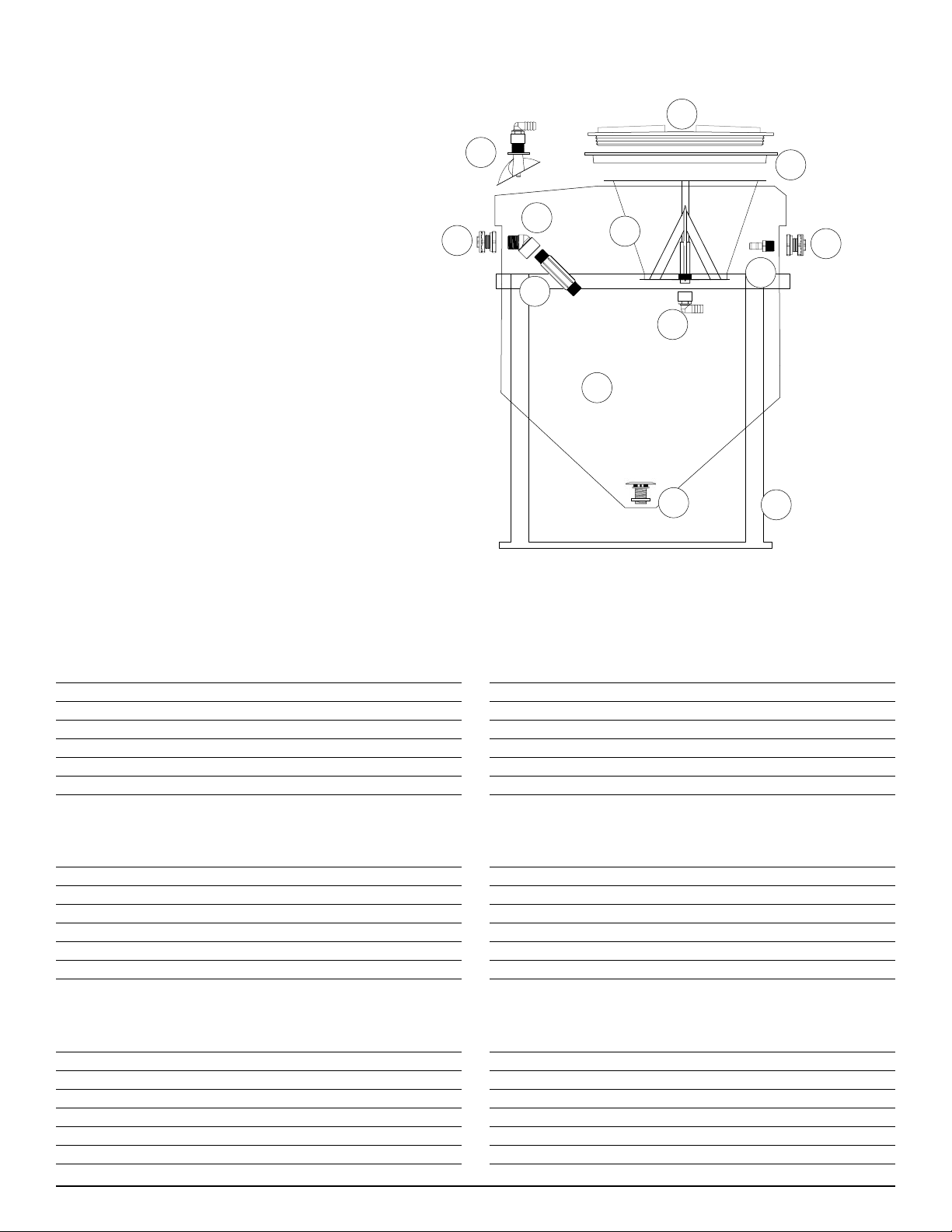
12
4
5
3
10
7
6
9
8
6
11
1
2
Handler I, II & III Tank
Parts Breakdown
Handler I
# Part No. Description Qty
1 86-H1T15 Handler I tank 1
2 86-H1FSFRA Handler I frame 1
3 85-HKNIFE Handler knfire 1
4 10-15080 15” polypropylene closed lid 1
5 10-15090G 15” gasketed polypropylene rim 1
6 42-38020 3/4” FPT bulkhead 2
Handler II
# Part No. Description Qty
1 86-H2T35 Handler II tank 1
2 86-H2FRA Handler II frame 1
3 85-HKNIFE Handler knfire 1
4 10-15080 15” polypropylene closed lid 1
5 10-15090G 15” gasketed polypropylene rim 1
6 25-TF100 1” FPT bulkhead 2
Handler III
# Part No. Description Qty
1 86-H3T60 Handler III tank 1
2 86-H3FRA Handler III frame 1
3 85-HKNIFE Handler knfire 1
4 49-62532 15” hinged polypropylene lid and rim 1
5 N/A
6 25-TF100 1” FPT bulkhead 2
# Part No. Description Qty
7 30-60400P 3/4” MPT x HB 90 1
8 30-60400P 3/4” MPT x HB 90 1
9 N/A
10 30-60974PHK 3/4” FPT x HB 90 - Drilled 1
11 10-14170 1 1/4” anti-vortex fitting 1
12 N/A
# Part No. Description Qty
7 30-60450 1” MPT x 3/4” HB 90 1
8 25-HB100-90 1” MPT x HB 90 1
9 N/A
10 30-60974PHK 3/4” FPT x HB 90 - Drilled 1
11 10-14210 2” anti-vortex fitting 1
12 N/A
# Part No. Description Qty
7 30-60450 1” MPT x 3/4” HB 90 1
8 25-SL100-45 1” MPT x FPT street elbow 45 1
9 25-NIP100-6 1” x 6” MPT nipple 1
10 30-60974PHK 3/4” FPT x HB 90 - Drilled 1
11 10-14210 2” anti-vortex fitting 1
12 49-PWRF-15 RotaFlush 1
42 Handler I, II & III Operator’s Manual - October 2008
Page 43

System Specifications
Handler I
Tank: Polyethylene.
•
Capacity: 15 US Gallons or 59 Lites.
•
Frame: Powder coated steel.
•
Fittings: Fiberglass filled polypropylene.
•
Hose: Clear braided PVC (pressure side) or PVC suction
•
(suction side of system).
Clamps: All stainless steel.
•
Lid: 15 inch polypropylene.
•
Venturi: 1 ½” fiberglass filled polypropylene (Threaded p/n
•
85-HV150, Manifold p/n 85-HV150FLA)
Venturi performance (volume draw): 35 US Gallons/minute
•
(29 imperial gallons / minute or 131 liters/ minute) at an
operating pressure of 50 psi.
NOTE: Venturi performance may vary depending on
•
application, conditions, restrictions and pressures. Per-
formance data is based on water.
Height: 35” with lid on.
•
Width: 21” for tank and frame (without plumbing attached),
•
20” tank only.
Handler II
Tank: Polyethylene.
•
Capacity: 42 US Gallons or 160 liters.
•
Frame: Powder coated steel.
•
Fittings: Fiberglass filled polypropylene.
•
Hose: 1” clear braided PVC or 1 1/2 “ PVC suction or 2”
•
Ribbed EPDM Kanaflex.
Clamps: All stainless steel.
•
Lid: Polypropylene, 15’ closed lid with gasketed rim.
•
Venturi: 2” flanged, fiberglass filled polypropylene.
•
Venturi performance: 49 US Gallons/minute (41 imperial
•
gallons or 186 liters/minute) at an operation pressure of 50
PSI.
NOTE: Venturi performance may vary depending on
•
the application, product, conditions, restrictions and
pressure. Performance data is based on water.
Height: 40” with lid on.
•
Width: 34” with plumbing (27” diameter without plumbing).
•
Length: 32” with plumbing only, 53” with pump bracket
•
and pump attached.
Handler III
Tank: Polyethylene.
•
Capacity: 70 US Gallons or 275 liters.
•
Frame: Powder coated steel.
•
Fittings: Fiberglass filled polypropylene.
•
Hose: 1” clear braided PVC , 1 1/2 “ PVC suction , 2 or 3 ”
•
Ribbed EPDM Kanaflex.
Clamps: All stainless steel.
•
Lid: Polypropylene, 15’ diameter hinged lid with check
•
valve breather.
Venturi: 2” flanged, fiberglass filled polypropylene.
•
Venturi performance: 49 US Gallons/minute (41 imperial
•
gallons or 186 liters/minute) at an operating pressure of 50
PSI.
NOTE: Venturi performance may vary depending on
•
the application, product, conditions, restrictions and
pressure. Performance data is based on water.
Height: 44” with lid on.
•
Width: 44” with plumbing (36” diameter without plumbing
•
attached).
Length: 44” with plumbing only, 56” with pump bracket
•
and pump attached.
NOTE: Specifications subject to change without notice.
43Handler I, II & III Operator’s Manual - October 2008
Page 44
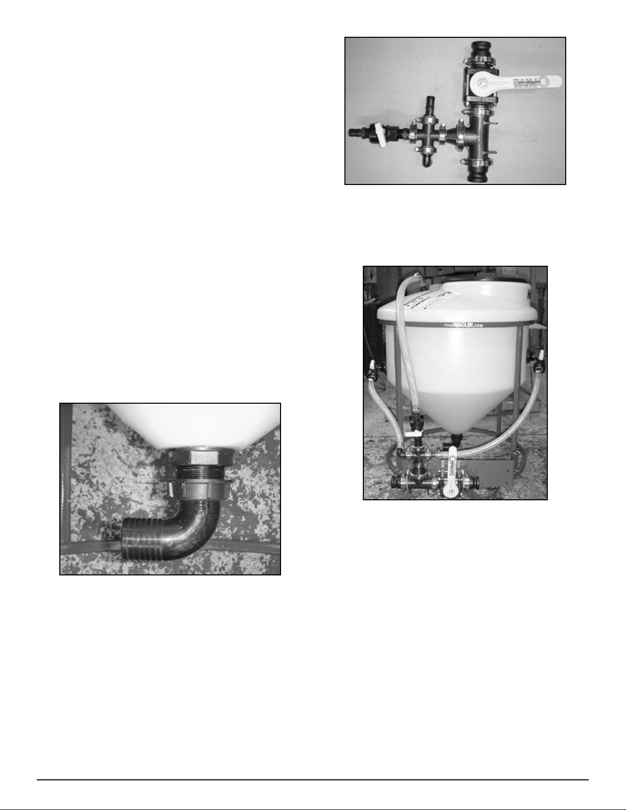
Plumbing Package
Assembly
(Handler 3)
Overview
Although not very common, some customers prefer to purchase
and use the Handler as an induction system rather than an eduction system. In the induction system the venturi is removed and
the pump is used to both pressurize the system when adding
fresh water through agitation and when rinsing containers with
fresh water, and to remove mix liquids and concentrated chemical solutions from the tank. This appendix to the Handler I, II
& III manual gives assembly and operational instructions for
the Handler III plumbing package systems offered by Focus
Industries.
Assembly & Installation
Handler III 2” Manifold Plumbing
Figure H3P-4.2
Assemble 2” plumbing package. (See Fig H3P-4.2)
2.
Install plumbing assembly to venturi bracket using bolts and
3.
U-bolts provided. Tighten.
Figure H3P-4.3
Measure, cut and install 1” hose (See Fig H3P-4.3) con-
4.
necting agitation/rinse assemblies and RotaFlush to cross.
Secure hose with clamps.
Attach customer supplied 2” suction hose to 2” hose barb
Figure H3P-4.1
Thread (without using sealant) 2” FPT x 2” hose barb 90
1.
degree, 10-10930 to anti-vortex fitting on tank bottom. Turn
hose barb to desired position and tighten fly-nut. (See Fig
H3P-4.1)
NOTE: Check flynut on anti-vortex fitting and tighten as
•
necessary with pump pliers. Do not overtighten.
44 Handler I, II & III Operator’s Manual - October 2008
5.
assembly on tank bottom. Secure with clamps provided.
Check and tighten all clamps and bolts as necessary.
6.
NOTE: For optional recirculation package
installation instructions see page 26.
Page 45
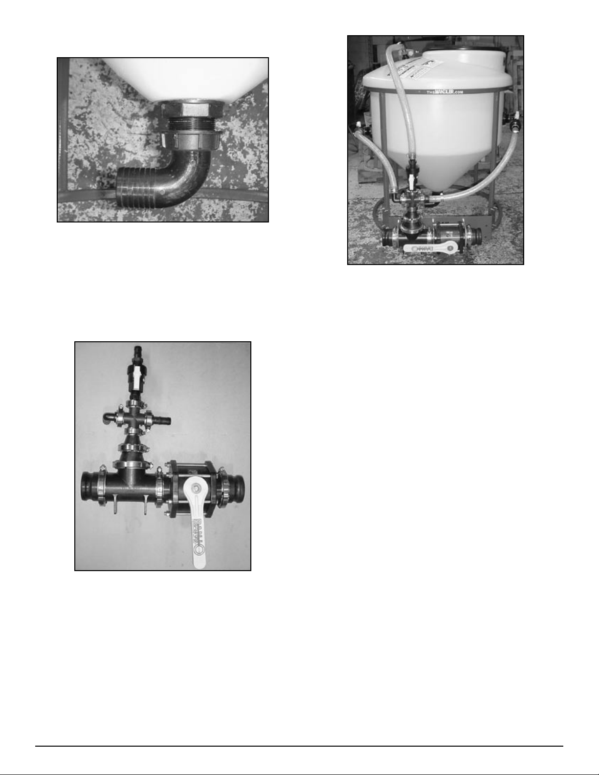
Handler III 3” Manifold Plumbing
Figure H3P-4.4
Thread (without using sealant) 2” FPT x 2” hose barb 90
1.
degree, 10-10930 to anti-vortex fitting on tank bottom. Turn
hose barb to desired position and tighten fly-nut. (See Fig
H3P-4.4)
NOTE: Check flynut on anti-vortex fitting and tighten as
•
necessary with pump pliers. Do not overtighten.
Figure H3P-4.6
Measure, cut, and install 1” clear braided hose. (See Fig
4.
H3P-4.6) Connecting agitation/rinse assemblies and rota
flush to cross assembly. Secure hose with MC12 clamps, 53-
75612.
Attach customer supplied 2” suction hose to 2” hose barb
5.
assembly, 10-10930 on tank bottom. Secure with MC32
clamps, 53-75632 supplied.
Check and tighten all clamps and bolts as necessary.
6.
Figure H3P-4.5
Assemble 3” plumbing package. (See Fig H3P-4.5)
2.
Install plumbing assembly to venturi bracket using three
3.
3/8” x 4” U-Bolts 67-UB38-400. Tighten all bolts and UBolts.
NOTE: For optional recirculation package
installation instructions see page 26.
45Handler I, II & III Operator’s Manual - October 2008
Page 46
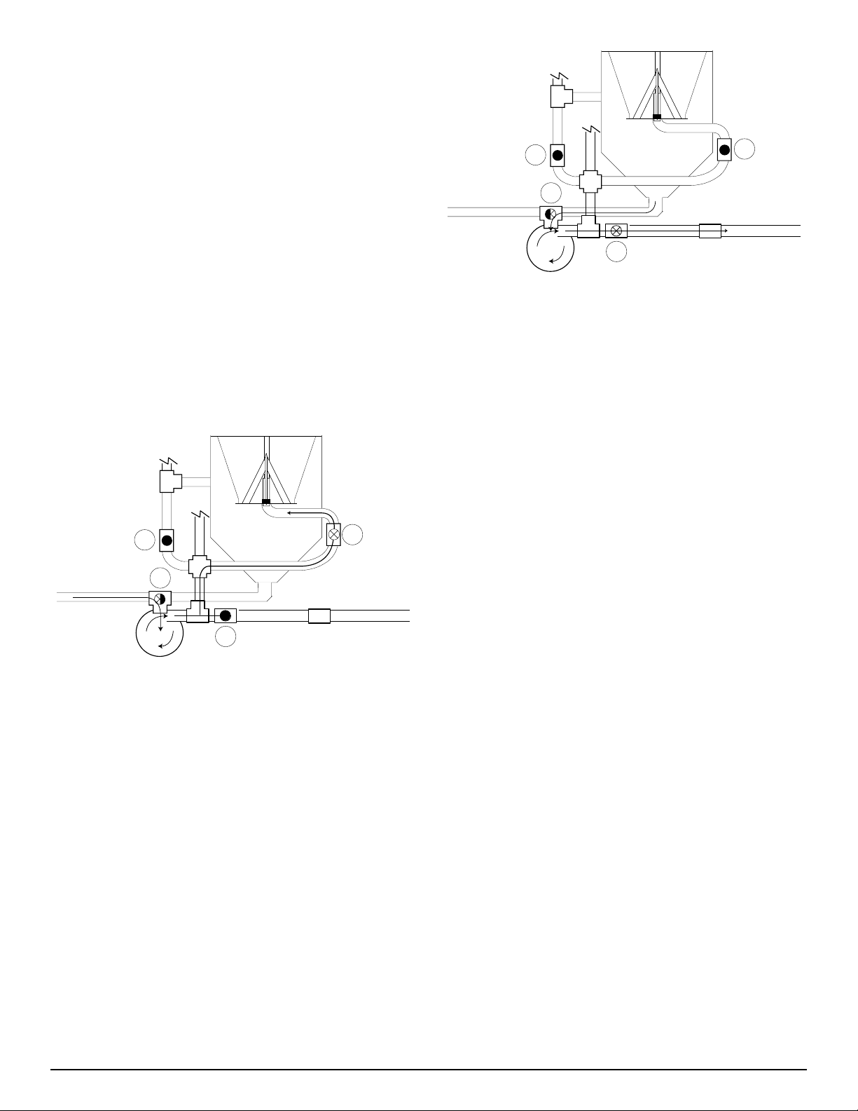
Plumbing Package
1
2
3
4
1
2
3
4
Operation
(Handler 3)
Mixing Liquid Product
Valve #1 (3 way ball valve on suction side of pump) in the following instructions is part of the optional recirculation package,
and is not included with the package you purchased.
Before adding water, set the ball valves by closing valve #2,
1.
#3 and #4.
Set valve #1 to receive fresh water.
2.
Start your pump.
3.
Place the container into the tank and puncture from the bot-
4.
tom. Push it down with consistant, even pressure to cut the
bottom and allow it to drain.
Figure H3P-5.2
To drain rinsate from tank, first close RotaFlush valve, turn
1.
valve #1, to draw from Handler tank. Next open valve #3 to
send rinsate to sprayer. (See Fig. H3P-5.2)
Once the Handler tank has been cleaned of all product
2.
residue, turn off the RotaFlush valve and turn on valve #1 to
receive fresh water and continue to fill the sprayer until it is
at the desired level.
Shut off your pump.
3.
Figure H3P-5.1
Open valve #4 to rinse the container. Before removing the
1.
container close valve #4 so the incoming fresh water does
not overflow the Handler tank or spray upwards. (See Fig.
H3P-5.1)
Repeat this process until the desired amount of chemical has
2.
been mixed.
To drain the Handler tank, set valve #1 to receive the
3.
product from the Handler tank. Open valve #3 to send the
product to the sprayer.
To rinse replace the lid, close valve #3 and turn valve#1 to
4.
receive fresh water. Open the valve to the RotaFlush nozzle
(not shown) and thoroughly rinse the Handler tank.
46 Handler I, II & III Operator’s Manual - October 2008
Page 47
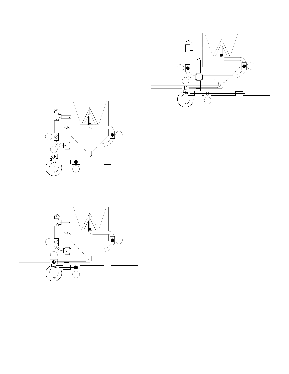
Mixing Dry and Packaged Products
1
2
3
4
1
2
3
4
1
2
3
4
Recirculation Instructions for both Liquid
and Dry products.
Valve #1 (3 way ball valve on suction side of pump) in the following instructions is part of the Optional Recirculation package
and is not included with the package you purchased.
Before turning on your pump, ensure that valve #1 is set to
1.
receive fresh water, that valve #2 (agitation valve) is open
and that all other valves are closed.
Turn on your pump and begin the flow of water.
2.
Figure H3P-5.3
Fill the Handler tank with the desired amount of fresh water.
3.
(See Fig. H3P-5.3)
Once the desired mixture is achieved, turn off valve #2 to
7.
prevent continued recirculation.
Figure H3P-5.5
Turn valve #3 to send the mixture to the sprayer. (See Fig.
8.
H3P-5.5)
When tanks contents has drained from the Handler tank,
9.
replace the lid, turn off valve #3 and turn valve #1 to receive
fresh water. Turn on the valve to activate the RotaFlush
tank rinser (not shown).
To drain rinsate from tank, first close rota flush valve and
10.
follow steps #4, #7 and #8. (See Fig. H3P-5.5)
Once the tank has been cleaned and drained of all product
11.
residue, turn valve #1 to receive fresh water and with all
other valves closed except for valve #3, allow water from
the source to continue filling the sprayer tank.
When the sprayer is full, close valve #3 and stop the pump
12.
at the source. This will terminate all fresh water entering
the system. The adding procedure should now be complete.
Figure H3P-5.4
Turn valve #1 to receive product from the bottom of the
4.
Handler. (See Fig. H3P-5.4)
Slowly pour dry or packaged products into the Handler tank.
5.
Allow ample water to product ratio to prevent product from
clogging.
If more water needs to be added to the tank, turn valve #1 to
6.
receive fresh water.
NOTE: Repeat above steps until desired amount of mix-
•
ture is attained.
47Handler I, II & III Operator’s Manual - October 2008
Page 48

48 Handler I, II & III Operator’s Manual - October 2008
 Loading...