

Focus Foodservice Shelving Wire Assembly Instructions [en, es]
INSTRUCTIONS
FOODSERVICE, LLC
Note: Please dispose of loose, round plastic pieces. These are used to separate the shelves
for shipping purposes.
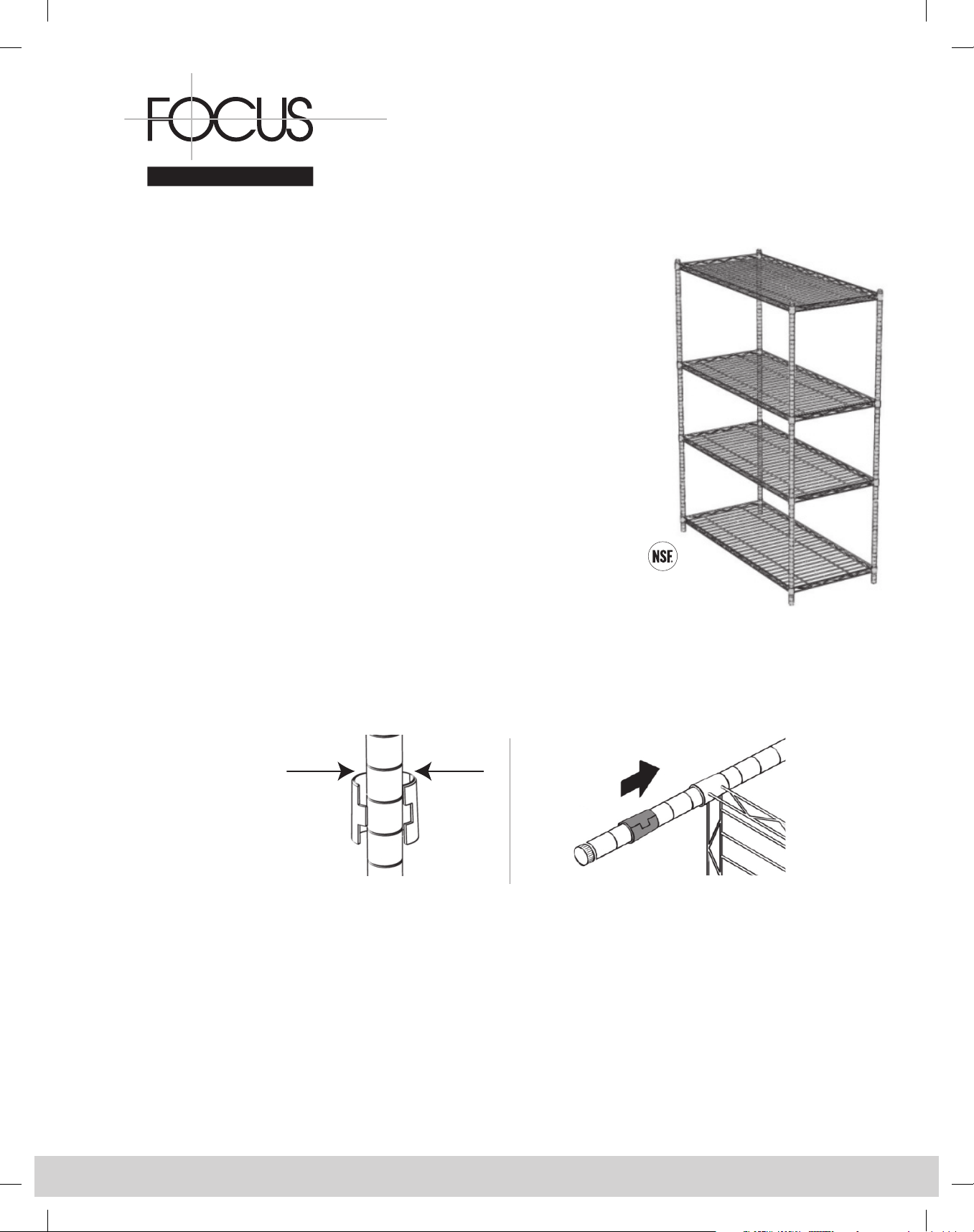
Helpful Hint: When placing the plastic tapered sleeves onto the posts (Step 1), slide the
plastic tapered sleeves up or down on the post until you feel it “snap” into the lines or grooves
of the post. It is normal to have a slight gap in-between the two pieces of the plastic tapered
sleeves when it is placed on the post.
Step 1 For mobile version, install casters into bottoms of posts.
Step 2 Choose the desired height of the bottom shelf (for added stability, it is recommended
that the bottom shelf is installed no more than 6"(2 – 3 lines) from the floor and the
top shelf no more than 6"(2 – 3 lines) from the top.) Snap two (2) tapered sleeves,
with the word UP on top, at the desired height on each post. Shelves can be adjusted
every 1". (Note: Double grooves in the posts are placed every 8th groove for simple
shelf height reference.)
Step 3 Place shelf on its side, making sure the wider portion of the four (4) round shelf
collars are facing the bottom of the unit, slide the top of the posts through the
round shelf collars on each corner of the shelves. Push the shelves firmly onto
the tapered sleeves.
Step 4 After installing the bottom shelf, set the unit upright.
Step 5 Snap the tapered sleeves into place on posts at the next desired shelf height. Slide
the shelf down from the top of the posts onto the tapered sleeves and repeat this
step for the remaining shelves. (Note: A rubber mallet may be used to tap each corner
of the shelves so they firmly install onto the tapered sleeves. Note: The leg levelers may
need to be utilized in order to make the unit level or flush against the wall.)
ASSEMBLY
Wire Shelving
WARNING: HEAVY OBJECTS MUST BE PLACED--NOT DROPPED--ONTO THE SHELVES!!
DIAGRAM 1
Top
Top
DIAGRAM 2
continued on backside
ASSEMBLY INSTRUCTIONS
Model# FXHAND18C 18" Chromate Side Handle
Model# FXHAND24C 24" Chromate Side Handle
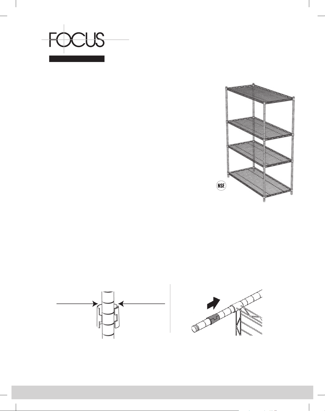
Helpful Hint: When placing the plastic tapered sleeves onto the posts, slide the plastic
tapered sleeves up or down on the post until you feel it “snap” into the lines or grooves of the post.
It is normal to have a slight gap in-between the two pieces of the plastic tapered sleeves when it is
placed on the post.
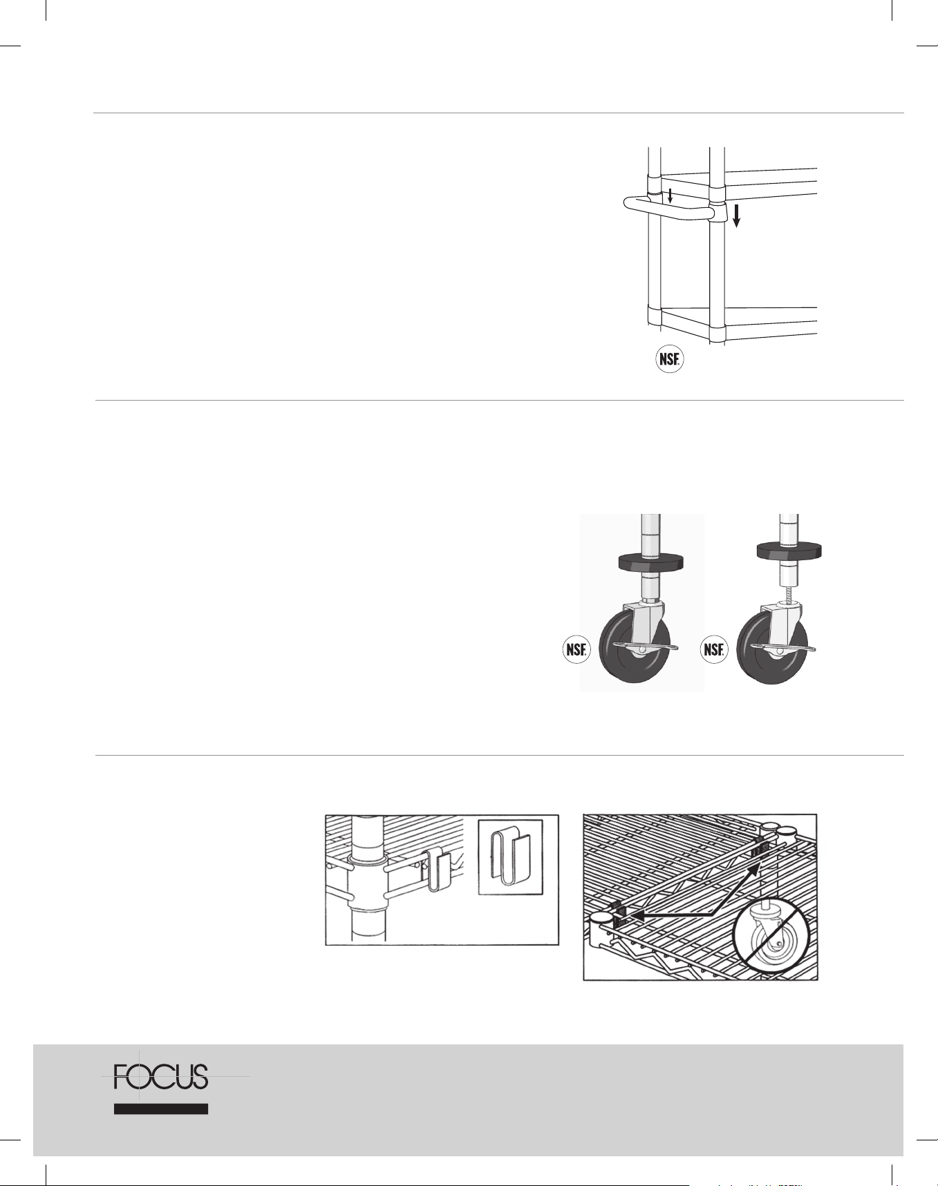
Installing the Side Handle
Install handle on the two posts that are 18˝ apart and choose the desired height for the side
handle (Note: Handles can be adjusted every 1˝). Snap 2 plastic tapered sleeves into place
on each post at the desired height. With the wider portions of the round collars facing the
bottom of the unit, slide the side handle down from the top of the posts onto the plastic
tapered sleeves. (Note: Make sure to leave enough room to install shelf above handle. )
Model# FTPRCST5 5" TRP Stem Casters with Bumpers
Model# FSCAST5 5" Polyurethane Stem Casters with Bumpers
Model# FTCAST5 5" Polyurethane Threaded Casters with Bumpers
Step 1 Slide a plastic bumper up the bottom of post about 4˝ - 6˝, smooth side facing up.
Step 2 For stem - Install caster by inserting it into the hole in the bottom of the post.
For screw-in - Remove leveling assembly by turning it counter-clockwise.
Install caster by screwing it into the hole at the bottom of the post.
Step 3 Slide the plastic bumper down to the bottom of the post.
Step 4 Repeat these steps to install the remaining 3 casters.
Step 5 Then assemble shelving unit.
Note: The casters can be locked in place by turning the steel lock mechanism
counter clockwise on the side of two of the casters.
Weight capacity - Stem - 300 lbs. per caster
Screw-In - 200 lbs. per caster
5" Industrial Stem
Casters with Bumpers
S Hooks/Shelf Connectors
Model# 93333 Chromate
Model# 93333GN
Green Epoxy Coated
Two per shelf required.
5" Industrial
Screw-In Casters
with Bumpers
FOODSERVICE, LLC
Call Customer Service at 1.800.968.3918 | Fax 1.800.968.4129
www.focusfoodservice.com
rev. 1212
INSTRUCCIONES
FOODSERVICE, LLC
DE MONTAJE
Anaqueles de Alambre
Nota: Sírvase desechar la piezas plásticas redondas sueltas. Éstas son utilizadas para
separar los anaqueles durante el transporte.
Sugerencia util: Al colocar las mangas de plástico ahusadas en los postes (Paso 1),
deslice dichas mangas hacia arriba o abajo del poste hasta que sienta que "encajan" dentro
de las muescas del poste. Es normal que quede una ligera separación entre las dos piezas de
las mangas de plástico ahusadas al colocarlas en el poste.
Paso 1 Para la versión móvil, instale las ruedas en la par te de debajo de los postes.
Paso 2 Escoja la altura deseada del anaquel inferior (para mayor estabilidad, se
Paso 3 Coloque el anaquel sobre su lado, asegurándose de que la parte más ancha
Paso 4 Tras instalar el anaquel inferior, coloque la unidad de pie.
Paso 5 Encaje las mangas de plástico ahusadas en su lugar en los postes en la próxima
´
recomienda que el anaquel inferior esté instalado a no más de 6'" (15 cm)
(2-3 líneas) del piso y el que el superior a no más de 6'" (15 cm) (2-3 líneas)
de la parte superior. Encaje dos (2) mangas de plástico ahusadas, con las
flechas cara arriba, a la altura deseada en cada poste. (Vea el Diagrama No.1)
Los anaqueles pueden ajustarse cada 1" (2,45 cm). (Nota: en cada 8va.
muesca, se colocan muescas dobles para brindar una sencilla referencia de la
altura del anaquel.)
de los 4 collares redondos esté de cara hacia la parte inferior de la unidad;
deslice la parte superior de los postes a través de los collares redondos en
cada esquina de los anaqueles. Presione el anaquel firmemente sobre las
mangas de plástico ahusadas. (Vea el Diagrama No. 2)
altura de anaquel deseada. Deslice el anaquel desde la parte superior de los
postes hacia abajo hasta las mangas de plástico ahusadas y repita este paso
para los anaqueles restantes. (Nota: puede utilizarse un mazo de goma para
golpear ligeramente cada esquina de los anaqueles de manera que queden
firmemente instalados sobre las mangas de plástico usadas.) (Nota: pudieran
necesitarse utilizar los niveladores de patas a fin de que la unidad quede a nivel
o al ras contra la pared.)
ADVERTENCIA: ¡LOS OBJETOS PESADOS DEBEN COLOCARSE - NO DEJARSE
CAER - SOBRE LOS ANAQUELES!
DIAGRAMA 1
Parte superior
Parte superior
DIAGRAMA 2
continúa en el reverso
 Loading...