

FOCUS Enhancements MX-4DV User Manual

DISCLAIMER
Television screens are simulated and subject to change without
notice. This device is not to be used for the unauthorized copying of
copyrighted material.
TRADEMARKS
MX-4 DV, the FOCUS Enhancements logo, and MX-4 DV are
trademarks or registered trademarks of FOCUS Enhancements Hi8
and i.LINK are trademarks of Sony Corporation. FireWire is a registered trademark of Apple Computer. VHS is a registered trademark of JVC. Other product and brand names might be trademarks
or registered trademarks of their respective companies and are
hereby acknowledged.
FOCUS Enhancements MX-4 DV User Guide, © 2004. No part of
this book may be reproduced in hard copy, electronically, or by any
other means without the expressed, written permission of FOCUS
Enhancements
FCC Statement
This equipment has been tested and found to comply with the limits
for a Class A digital device, pursuant to part 15 of the FCC Rules.
These limits are designed to provide reasonable protection against
harmful interference when the equipment is operated in a commercial environment. This equipment generates, uses, and can radiate
radio frequency energy and, if not installed and used in accordance
with the instruction manual, might cause harmful interference to
radio communications. Operation of this equipment in a residential
area is likely to cause harmful interference, in which case the user
must correct the interference at his/her own expense.
MANL-0956-01

CONTENTS
DISCLAIMER • 2
TRADEMARKS • 2
FCC Statement • 2
1INTRODUCTION
Major Features • 2
Common Uses for MX-4 DV • 4
MX-4 DV Package Contents • 5
About this User Guide • 6
2QUICK START
Quick Start Steps • 10
Setting Up • 10
The Preview Screen • 11
Running the Demo • 12
Cutting Between Sources • 13
Borders and Solid Color Backgrounds • 13
Setting up a Transition • 13
Running Transitions • 14
Using CUT Transitions • 14
Choosing Transitions • 15
Using Transition Categories • 15
Other Features • 15
3INSTALLING THE MX-4 DV
Sources and Output • 18
Preview and Program Monitors • 18
Preview Monitor • 19
Program Monitor • 19
Number of Monitors • 19
Understanding MX-4 DV Connectors • 20
Power Connector • 22
Cables and Adapters • 22
Installation Examples • 24
Correlating Input Sources to MX-4 DV Jacks • 24
Using Headphones • 25
VCR Selector Switches • 25
General Notes • 25
Post Production Configuration • 26
Live Broadcast Configuration • 28
Using a Microphone with MX-4 DV • 30
4BASIC OPERATIONS
Starting and Stopping the MX-4 DV • 32
Understanding the Keyboard • 32
Using the Preview Screen • 35
Changing the Display Configuration • 35
Input Source Previews • 36
Active Source Highlights • 36
Color Selector • 37
Transitions Menu • 37
Selected Transition • 37
Using CURRENT and NEXT Sources • 38
Selecting Sources • 39
Using the Video/Audio Selector • 39
Swapping Sources • 40
Simple Cuts • 40
Swapping Between Two Sources • 40
Working with Colors • 41
Identifying Colors • 42
Using Color Backgrounds • 42
Changing Colors and Styles • 42
Creating Custom Colors • 43
Using Borders • 43
Changing Border Styles • 44
5TRANSITIONS
Basic Transition Concepts • 48
Transition Categories and Menus • 50
Basic Transitions Category • 51
Edges Transitions Category • 51
Misc. Transitions Category • 51
Shapes Transitions Category • 51
User Transitions Category • 51
Changing User Transitions Menu • 52
Selecting Transition Sources • 53
Setting the CURRENT Source • 53
Setting the NEXT Source • 53
Selecting Transitions • 54
Using the Transitions Menu • 54
Using Transition Numbers • 55
Adjusting Transitions • 56
Changing Transition Speed • 56
Changing Transition Direction • 56
Running Transitions • 58
Running Transitions Automatically • 58
Running Transitions Manually • 58
6INPUT EFFECTS
Input Effects Menu • 60
Special Key Combinations • 61
Using Input Effects • 62
B&W • 63
B&W Neg • 63
Posterize • 63
Flip Horizontal • 63
Mosaic • 64
Color Correct • 64
Color Neg • 64
Video Adjustment • 65
Chromakey • 65
Flip Vertical • 65
Strobe • 65
7FUNCTIONS
Demo • 68
Running a Locked Demo • 68
Display • 69
Setup • 71
Force Field Freeze • 72
GPI Out Mode • 72
Comb Filter • 72
Audio Mode • 72
Dual Monitor Mode • 72
7.5 IRE Pedestal • 72
FTP • 73
Route • 73
Configuring the MX-4 DV • 73

CONTENTS
Changing the Routing • 74
Example: Changing the Routing • 75
Routing Audio Through Color or Background Channels • 76
Sub-Route Menus • 77
Learn • 78
Compose • 79
PIPs • 79
Audio Mix • 79
Freeze • 79
Field and Frame Freezes • 79
Major Freeze Functions • 80
Freeze Examples • 80
8PIPS
Single PIP • 84
Background Tile • 84
Foreground Tile • 84
Using Other Effects with Single PIPs • 86
Multi-PIP • 87
Using Freeze Effect with Multi-PIPs • 88
9COMPOSE
Basic Composition Steps • 90
Backgrounds • 90
Foreground Tiles • 91
Creating Color Tiles and Lines • 91
Creating Moving Video Tiles • 91
Creating Still Image Tiles • 91
Manipulating Tiles • 91
Positioning Tiles • 91
Sizing Tiles • 92
Composition Rules • 92
Creating a Composed Image • 93
Playing the Composition • 94
Exiting from Compose Mode • 94
10 CHROMAKEY
Preparing the Background Footage • 96
Preparing the Keyed Footage • 97
Preparing the Chromakey Footage • 97
Performing the Chroma key • 99
Fine-Tuning Key Colors • 99
Ending Chroma Key • 99
11 LEARN MODE
Learned Environments • 102
Learned Scripts • 103
Using Learn Mode • 104
Other Useful Information • 105
Aborting a Playback Session • 105
12 WORKING WITH AUDIO
Audio Devices You Can Use • 108
Ways You Can Control Audio • 108
Controlling Audio Transitions • 108
VIDEO/AUDIO Selector • 108
Selecting Audio Sources • 109
Ways to Use Audio • 109
Audio Accompanies Video • 109
Continuous Audio • 110
Using the Audio Mixer • 111
Audio Mixer Controls • 112
Using Background Audio • 112
Using Headphones • 113
Advanced Audio Steps • 113
Using the Analog Audio Adjustments Function • 113
Selecting Manual Levels • 114
Selecting Audio Delay • 114
13 ADVANCED OPERATIONS
Using Titles • 116
Using Color Bars • 116
Performing Roll Edits • 117
Cutting Between Scenes • 117
A/A Roll Edits • 117
A/B Roll Edits • 118
Transitions TO and FROM Solid Colors • 118
Transitions to Modified Sources • 119
Operating in Live Environments • 119
Security Monitoring • 119
Using a GPI Device • 120
Instructions for Building a GPI Trigger • 121
Using a GPI Trigger Device • 122
Resetting the MX-4 DV Factory Defaults • 122
Connecting with Ethernet • 123
IP Setup for a Computer or Laptop • 124
Transferring Files TO or FROM the MX-4 DV • 130
Updating System Software • 131
Information About FTP Clients • 132
ATRANSITIONS LIST 135
Basic Transitions • 136
Edge Transitions • 144
Misc. Transitions • 145
Shape Transitions • 146
Default User Transitions • 151
BTIME BASE CORRECTOR 153
Dual TBC Mode • 153
Vertical Interval Data • 153
TBC Technical Information • 154
CVIDEO QUALITY 155
Preview Image Quality • 155
Video Scaling Artifacts • 156
Freeze Quality • 156
Video Processing Artifacts • 156
DTECHNICAL SPECIFICATIONS 157
ELP FOR MXPRO DV USERS 159
EH
MX-4 DV Defaults to Y/C on All 4-Channels • 159
Transitions Organized Differently • 159
Glossary
Index

CHAPTER 1
INTRODUCTION
Welcome to the MX-4 DV, and thank you for buying FOCUS Enhancements products.
This chapter contains:
• Brief descriptions of major MX-4 DV features
• Typical uses for the MX-4 DV
• How to contact FOCUS Enhancements
• An inventory of package contents
• Description of the contents of this User Guide
Please take a few moments to read the material so you can take full advantage of all
MX-4 DV benefits.
2
MX-4 DV USER GUIDE CHAPTER 1
MAJOR FEATURES
MX-4 DV contains features found on most video mixers. In addition, it contains the special features described in this section.
Superb Video Quality — To ensure the highest video quality, the MX-4 DV uses 10-bit (4:2:2)
video technology for Y/C applications, and 8-bit 4:2:2 for composite applications.
Four Input Synchronized Switcher — MX-4 DV provides four input channels that mix analog
sources. This makes MX-4 DV useful in live production settings where up to four cameras or other
sources might be in use. MX-4 DV synchronizes the inputs, so picture disruptions do not occur
when switching between sources.
Effects Generator — Use a variety of effects to enhance a source or transition between sources.
Select from over 700 effects, including natural shapes (diamonds, three leaf clover, and so forth),
fancy edges, and borders. You can also build your own custom menu for quick access to those
effects you use most often. Take advantage of FOCUS Enhancements downloadable subscription
site which provides additional new transitions and natural shapes to better serve your production
needs.
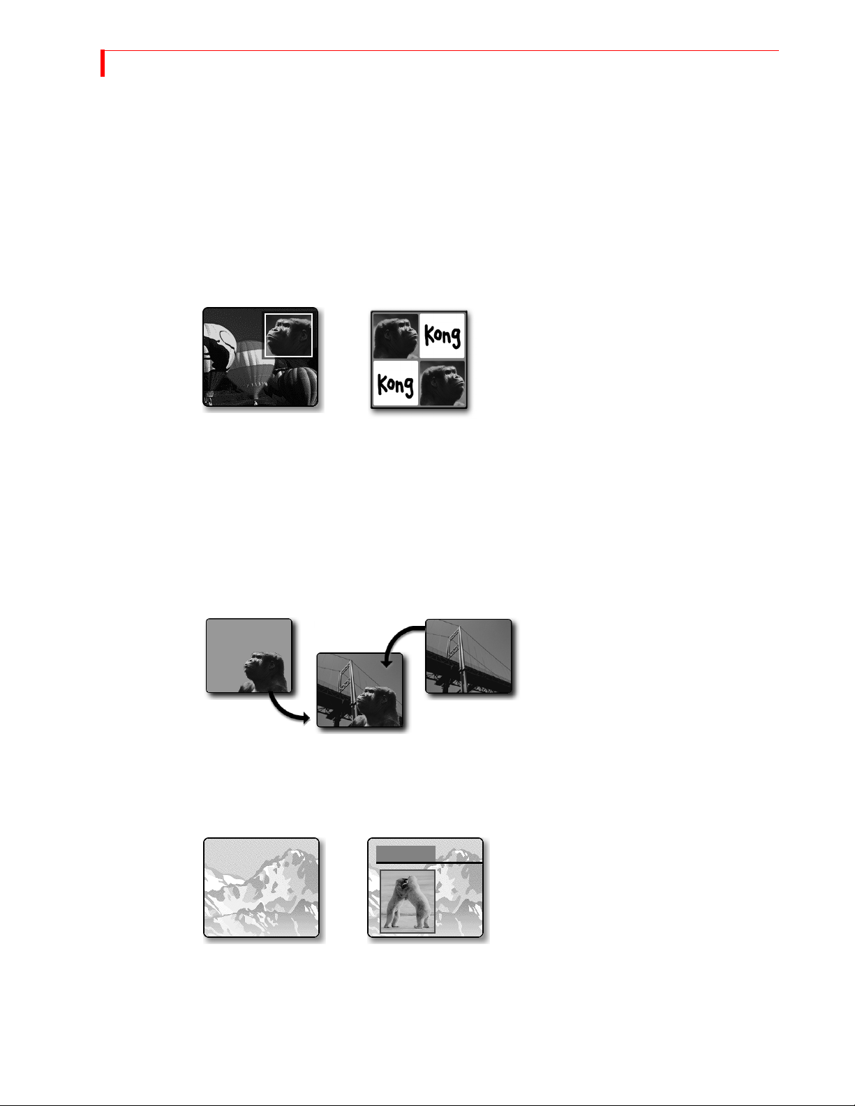
Picture-in-Picture (PIPs) — PIP allows multiple pictures to share the screen in various
configurations. For example, one source might
take the entire background while another
image appears inside a separate, smaller window, both sharing the screen at the same time.
You can use up to 4 images in a PIP configuration.
Time Base Corrector (TBC) — MX-4 DV automatically corrects the output’s time base. MX-4
DV stabilizes the output signal even when the input sources are not stable.
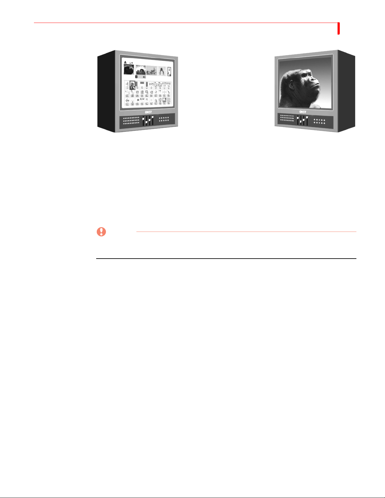
Chromakey — Keying replaces
parts of one picture with another,
based on their color. Here the solid
background behind Kong is replaced
by the picture of the bridge. The
chromakey version shows Kong contemplating the bridge.
Frame Synchronizer and Digital Video Mixer — Mix any two input sources together using a
variety of transitions — wipes, dissolves, flips, and so forth. With the frame synchronizer you can
mix independent video signals.
Compose — MX-4 DV provides a video
painting system you can use to combine video
stills, color shapes, and moving video on one
screen. You can create a screen that contains a
video still of a football coach (with a surrounding red border), combined with a moving video of the players in action on the field.
Audio Mixer — MX-4 DV provides sophisticated audio control. You can change the sound along
with the video, or play a constant sound while the video plays. Audio can come from a video
source or from external audio devices.

INTRODUCTION MAJOR F EATURES
Connectivity — MX-4 DV provides multiple video/audio outputs, including one DV output, two
Y/C Program outputs, two composite Program outputs, one composite Preview output, two sets of
stereo audio outputs, and a Headphone output.
Joystick — The joystick gives you fine control over color adjustments and positioning of PIP (picture-in-picture), compose, and the chromakey cursor.
Color Correction — Apply true RGB color correction to any or all input sources. Color correction
parameters can be set separately for each channel.
Input Effects — Apply special effects such as flips, mosaics, and others to the signals coming in
from any input source. You now have the ability to adjust the brightness, contrast, color saturation
and hue on your input sources and thumbnails.
Still Frame Jpeg Images — For the ultimate in creative expression, let the MX-4 DV allow you to
trigger a stand-alone jpeg clips for background, input, or foreground use in your live video production programming. You can import and store up to 100 jpeg images (50 background and 50 foreground) using the Ethernet connection on the back of your unit.
Ethernet — You can network your MX-4 DV to a Mac or PC using an Ethernet (10Base-T) connector. You can import backgrounds, bugs and still frame jpegs to or from your unit.
Gradients — You can access eight gradients using the graphics menu.
3
4
MX-4 DV USER GUIDE CHAPTER 1
COMMON USES FOR MX-4 DV
Multiple-Source Video Production — In a video production setup, you can connect one or more
video sources (VCRs, camcorders, video disc players, cameras, title generators, computer graphics
systems, and so forth) to MX-4 DV’s four input channels. The Program output can then be sent to a
VCR or directly to a monitor.
You can determine what is sent to the output. While the original inputs play, you can switch
between any of MX-4 DV’s channels. Use dissolves or other transitions to go from one channel to another. Add special effects to any channel, and use advanced features such as compose
and chromakey to enhance the production.
Single-Source Use — MX-4 DV supports A/A roll, a method for creating interesting transitions
with a single source. Its digital effects (such as picture freeze, posterization, and mosaic) give
added life to productions. You can use MX-4 DV with a titler to mix and superimpose titles. Time
base correction improves the picture (especially when making multiple-generation copies) by
removing the jitter common to most VCRs.
Live Video — In live production setups, MX-4 DV processes events as they occur. Good coverage
requires seeing the events from different vantage points—which means you need multiple input
sources. MX-4 DV gives you the ability to connect up to four sources simultaneously. For example, at a sporting event, camera one might focus on the playing field, camera two on the team
benches, camera three on the announcer, and camera four on the scoreboard. Using MX-4 DV you
can easily switch between the sources whenever necessary.
NOTE
MX-4 DV is not an edit controller — that is, it does not control VCRs, camcorders, and similar
devices. You can control the sources manually, or use external edit controllers such as those
manufactured by FOCUS Enhancements.
INTRODUCTION MX-4 DV PACKAGE CONTENTS
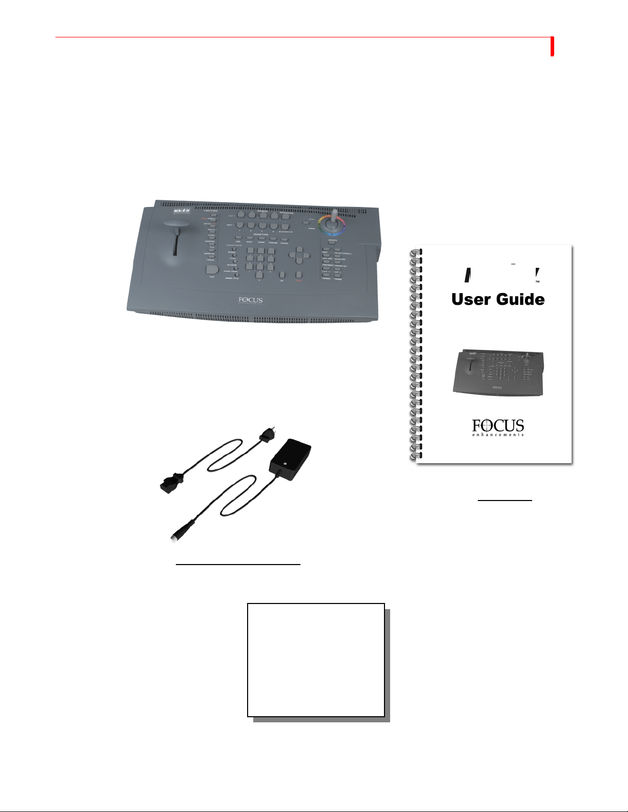
MX-4 DV PACKAGE CONTENTS
The MX-4 DV package contains the items shown below. Check your package against the illustration.
MX-4 DV Unit
MX-4 DV
5
POWER ADAPTER AND CORD
If your package doesn’t
contain all of the items
shown here, contact the
dealer where you purchased
the MX-4 DV for the
necessary replacements.
USER GUIDE
Product registration card
and other information

6
MX-4 DV USER GUIDE CHAPTER 1
ABOUT THIS USER GUIDE
This User Guide contains the chapters, appendixes, and other sections shown in the following
table.
Table 1: User Guide Contents
CHAPTER DESCRIPTION
Chapter 1
Introduction
Chapter 2
Quick Start
Chapter 3
Installing MX-4 DV
Chapter 4
Basic Operations
Chapter 5
Transitions
Chapter 6
Input Effects
Chapter 7
Functions
Chapter 8
PIPs
Chapter 9
Compose
Basic overview of MX-4 DV features, description of
package contents, description of manual.
Brief steps to setting up MX-4 DV with your equipment. Provided for people quite familiar with connecting video equipment.
Instructions for setting up MX-4 DV to work with
your video equipment.
Explains most common procedures and functions used
with MX-4 DV.
Complete description of and instructions for using
MX-4 DV transitions. Also see Appendix A, Transitions List.
How to use various effects with video input material.
Descriptions of and instructions for using MX-4 DV’s
built-in functions.
Instructions for using the picture-in-picture functions.
How to create composed images consisting of rectangles, lines, still images, and/or moving images.
Chapter 10
Chromakey
Chapter 11
Learn Mode
Chapter 12
Working with Audio
Chapter 13
Advanced Operations
Appendix A
Transitions List
Appendix B
Time Base Corrector
Appendix C
Video Quality
Instructions for creating chromakey images where specific colors (such as a blue screen) can be keyed out
and replaced with a video sequence or other image.
How to use MX-4 DV’s Learn Mode for “recording”
your mixing steps then playing them back.
How to use audio sources (tapes, CDs, and so forth)
with MX-4 DV.
Descriptions of operations used infrequently, but still
of substantial use for mixing video programs.
Complete list of transitions available with MX-4 DV,
along with their assigned code numbers and descriptions.
Explains the time-base corrector feature built into
MX-4 DV.
Discusses issues concerning the level of quality in videos — that is, what to expect and what you can do to
improve quality.
INTRODUCTION ABOUT THIS USER GUIDE
Table 1: User Guide Contents (continued)
CHAPTER DESCRIPTION
7
Appendix D
MX-4 DV product specifications.
Technical Specifications
Appendix E
Help for MXPro DV Users
Summarizes operational differences between MX-4
DV and FOCUS Enhancements’s Video Mixers.
Glossary Definitions of terms frequently used in conjunction
with MX-4 DV and video mixing procedures.
Index Standard index to topics in this manual.
Conventions The User Guide employs the conventions described in this section.
Tips, Notes, Cautions, and Warnings use the following formats.
TIP
A tip provides useful information for doing various tasks and procedures.
NOTE
Notes contain information to supplement the other information contained throughout the guide.
CAUTION
Cautions warn that if you continue with what you are doing there is a danger of losing information.
WARNING
Warnings mean stop what you are doing because there is danger of losing information and,
possibly, damaging your equipment.
MX-4 DV Buttons When referencing the various buttons (keys) and other controls on the MX-4 DV keyboard, they
appear in uppercase, boldface characters. For example, the keyboard contains the
T-BAR.
PLAY button and
In some cases you use two buttons together to perform a function. This is normally done using the
shift button in combination with some other button. A plus (+) symbol indicates this. For example,
SHIFT+PIPS to start MultiPIP mode. This means press and hold down
PIPs
Sources, Channels,
and Outputs
you might be asked to enter
SHIFT button, press the PIPS button, then release both.
the
SHIFT
The terms Source, Channel, and Output appear extensively throughout this guide. It’s important to
understand the differences between them.
A Source is a physical device, such as a VCR, that provides a video and/or audio signal.
A Channel is an internal MX-4 DV video signal path. The video and/or audio signal originating
from a source travels along one of the channels.

8
MX-4 DV USER GUIDE CHAPTER 1
An Output displays or records a mixed signal (such as the video on one channel, a transition, and
the video on another channel) on an output device. The output device might be a recording VCR or
a live broadcast signal.

CHAPTER 2
QUICK START
This chapter contains brief instructions for setting up MX-4 DV with basic equipment. The
instructions do not go into detail. If you feel comfortable connecting video and audio equipment, you can probably get started quickly using these instructions.
If you are upgrading from the Videonics MXPro DV, refer to Appendix APPENDIX E, Help
for MXPro DV Users, for helpful information in setting up your MX-4 DV.
Skim the instructions in this chapter. If you have any questions about any of the steps, turn to
Chapter 3, Installing the MX-4 DV, and follow the detailed instructions for setting up your
equipment.
10
MX-4 DV USER GUIDE CHAPTER 2
QUICK START STEPS
Setting Up
Input Source Input Source
Preview Monitor
PREVIEW OUT
IN 1
IN 2
OUT 1
Output Monitor
Output Device
• Connect a COMPOSITE-type monitor to MX-4 DV’s PREVIEW OUT jack.
• Connect an Input Source (such as a VCR or camcorder) to the MX-4 DV’s DV IN 1 jack.
• Connect a second Input Source to the MX-4 DV’s Y/C IN 2 jack.
The MX-4 DV is set up, by default, to expect DV devices to be connected to the DV IN 1 and
DV IN 2 input jacks, and S-Video (Y/C) devices to be connected to the IN 1 and IN 2 input
jacks. If you connect a different assortment of input devices, you must tell the MX-4 DV this
fact. Refer to “Route” beginning on page 73 after completing the following steps.
• Connect an output device to the OUT jacks on the MX-4 DV rear panel. This is the
device where you record the program.
Remember, a DV connector carries the audio signal as well as the video signal. It is, therefore,
unnecessary to make separate connections for these signals when using a DV device as output.
• Connect a television or monitor to the recording VCR according to their instructions.
Having this monitor available lets you see exactly what is being recorded (or, output).
NOTE
These instructions assume there is a two-monitor setup. If you are using only one monitor, connect
it to PREVIEW OUT.
QUICK START THE PREVIEW S CREEN
• Connect the MX-4 DV power supply to the power supply jack on the rear panel.
• Connect the MX-4 DV’s power cord to a suitable outlet.
• Turn on all devices (the MX-4 DV power switch is located on the right end of the unit)
and let the tapes roll.
For more detailed information about setting up your equipment, refer to Chapter 3, Installing the
MX-4 DV.
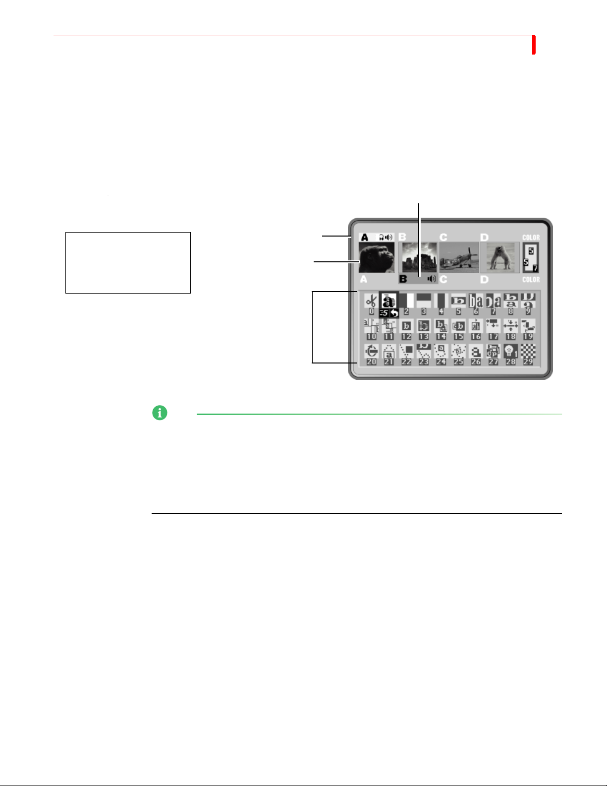
The Preview Screen
NEXT Source
CURRENT Source
You should see a Preview
screen similar to this on
your Preview monitor.
Previews
11
Transitions Menu
NOTE
The MX-4 DV provides a small preview screen in the user interface with the sources you have
attached. The images are scaled down in size, therefore, don’t play as smoothly as they would in a
single-source video monitor image. This does not affect the quality of the video going to the output
— it is always highest quality. In addition you will be able to view beforehand your source images
before running your transitions. Take advantage of the ability to adjust the Brightness, Color
Saturation, Contrast and Hue while viewing it on your preview screens. Refer to the video
adjustment menu section in Chapter 4 for these adjustments.
The PREVIEW screen contains the elements you need to run transitions:
CURRENT Source — The signal currently playing on your Output monitor. The MX-4 DV
highlights the CURRENT source in yellow (just above the preview images).
NEXT Source — The signal that will play on the Output monitor after the transition runs. The
MX-4 DV highlights the NEXT source in green.
Transitions M e n u — Rows and columns of icons representing some of the transitions available. The MX-4 DV highlights the currently selected transition in blue. The icons also show
the speed and direction for the selected transition.
Near the upper-right corner of the Preview screen is the color channel. The swatch uses numbers to
indicate the current background color, border color, and border style.
For more detailed information about controlling the content of the Preview screen, see “Using the
Preview Screen” beginning on page 35.
12
MX-4 DV USER GUIDE CHAPTER 2
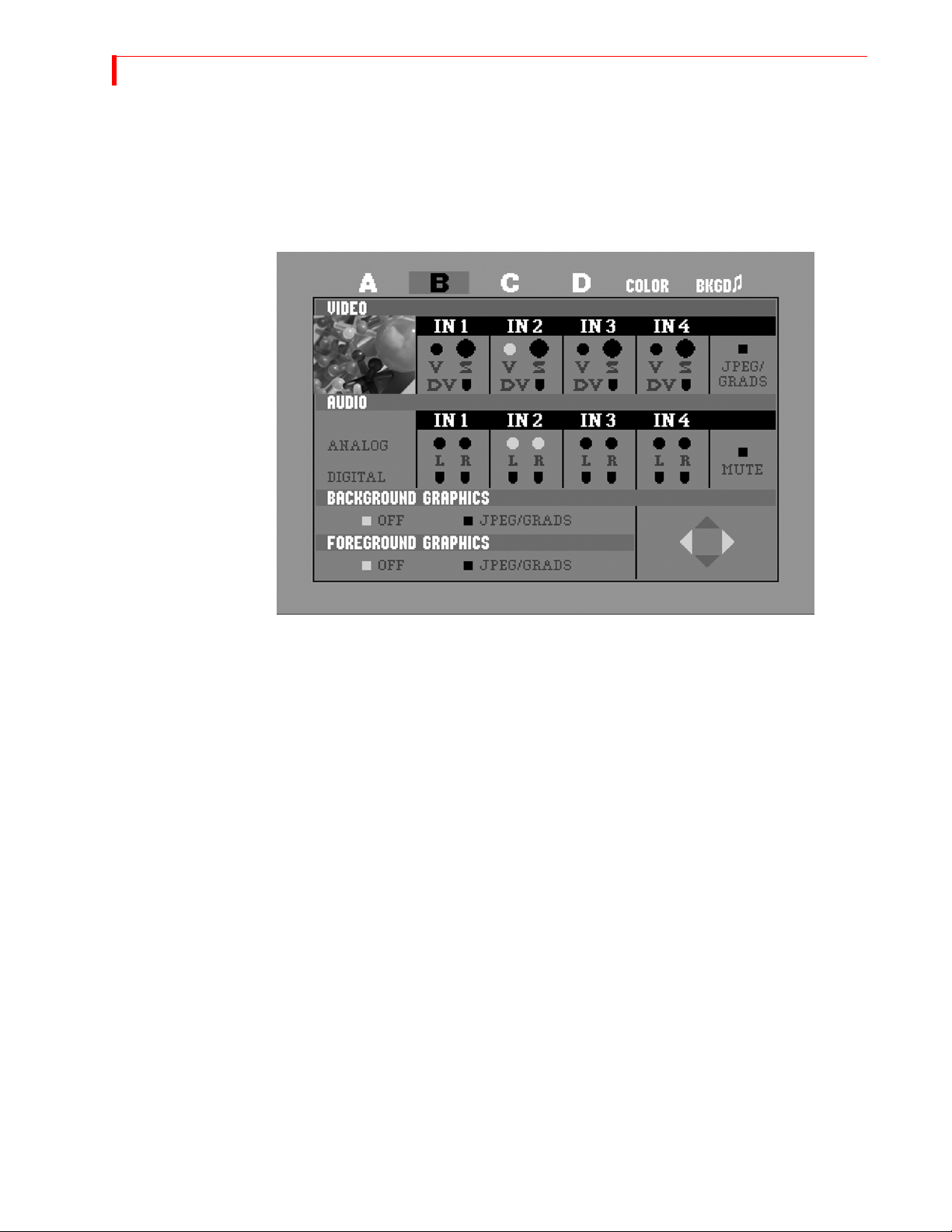
Using the Route
Function
The Route function ensures that the MX-4 DV understands where your input devices are connected
on the rear panel. If you connect Y/C devices to the IN1, IN2, IN3, and/or IN4 jacks, re-routing is
not necessary. Go on to the next section, “Running the Demo”.
• After starting the MX-4 DV with all devices connected and turned on, press ROUTE to display the Route screen.
Running the Demo
• Press the
LEFT ARROW or the RIGHT ARROW to select the appropriate input S
(Y/C), V (Composite), or DV.
• To route other inputs to different channels, press NEXT/X, where X represents the channel to which you want to route. Then repeat the preceding step.
• Press ROUTE again to exit from the Route screen.
The demo gives you a quick look at some of the MX-4 DV’s important features and assortment of
transitions.
•
Press the SHIFT+DEMO/DISPLAY buttons at the same time.
You should see the two sources alternating, with a variety of transition effects in between.
• Press any key to stop the demo at any time.
QUICK START CUTTING BETWEEN SOURCES
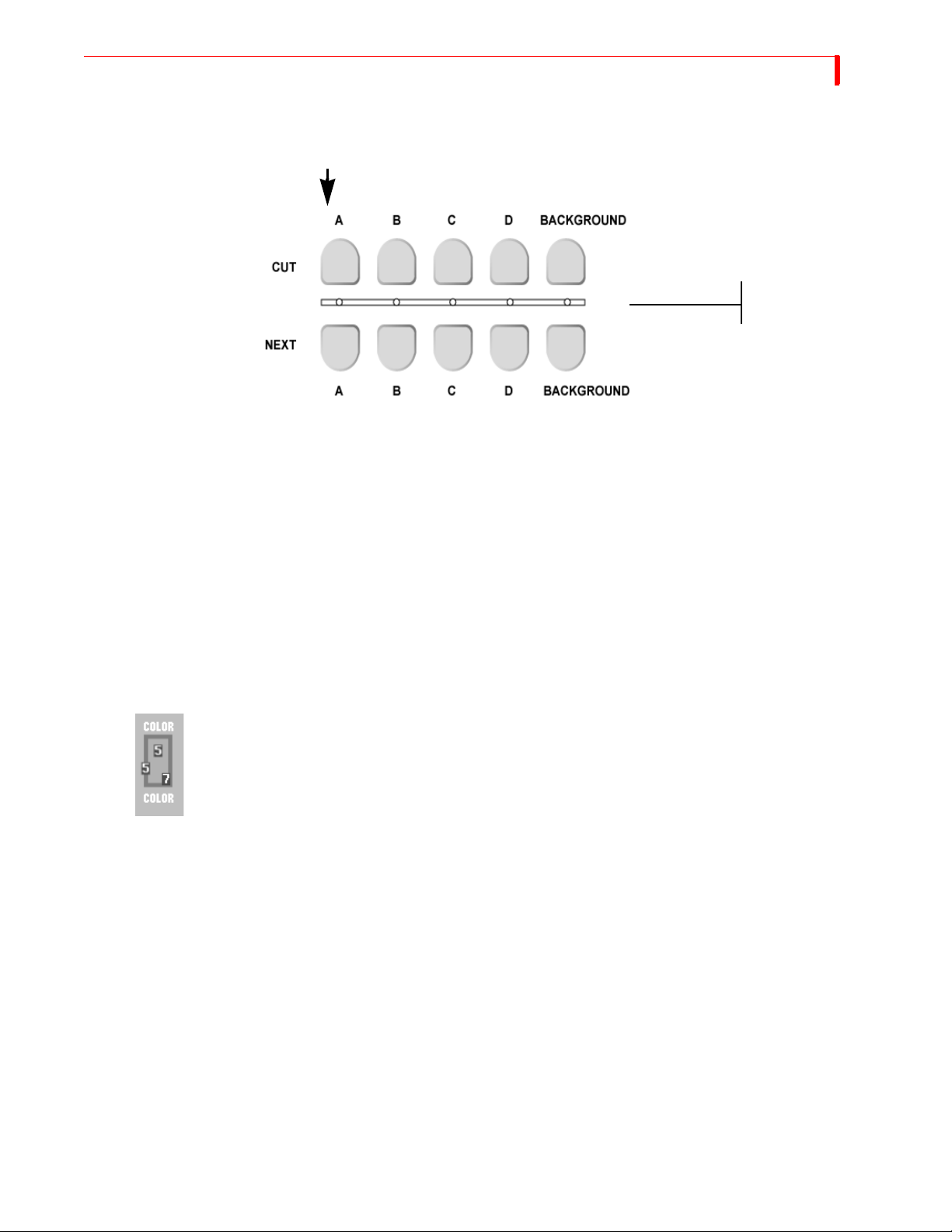
Cutting Between Sources
• Press CUT/A.
When you press a CUT button, the
small light below the button glows
steadily to indicate it is the CURRENT
source.
When you press a NEXT button, the
small light above the button blinks to
indicate it is the NEXT source.
The light below the A button comes on and the Output monitor displays the signal from whatever device is plugged into the inputs labeled IN 1. The yellow highlight above preview image
A tells you it is the currently active input.
Press CUT/B.
•
13
The light below the B button begins flashing (indicating B is both the CURRENT and NEXT
source) and the Output monitor displays the signal from whatever device is plugged into the
inputs labeled IN 2. The yellow highlight above preview image B tells you it is the currently
active input.
• If you have anything plugged into IN 3 or IN 4, press CUT/C and CUT/D, respectively, to
display their signals.
Borders and Solid Color Backgrounds
• Press CUT/BACKGROUND.
The MX-4 DV highlights the speaker, headphone, or color block above the channel indicator,
but does not show the channel letter. The Output monitor shows a solid color screen.
• To change the color, press
Each time you press the button the color changes in the background color sample and at the
Output. Continue pressing the button until you see a color you like.
• You can also define a border color and style to use at the edge of most transitions and
PIPs. Press
BORDER COLOR and the color around the background color sample shows
you the new choice. Press
Setting up a Transition
To set up a transition you need to select the sources you want to use and the transition you want to
use when switching between them. Here’s how to transition from source A to source B using a horizontal wipe.
• Press
• Press
• Use the
CUT/A to set A as the CURRENT source. The MX-4 DV shows a steadily glowing
light below the
NEXT/B to set B as the NEXT source (the one you want to see after the transition
CUT button you press.
finishes running). The LED light above the button you press flashes to indicate it is the
NEXT source.
ARROW keys to highlight the Wipe transition in the Transitions Menu, as shown
in the following example.
BG COLOR.
BORDER STYLE to select from different styles for the border.
14
MX-4 DV USER GUIDE CHAPTER 2
The MX-4 DV transitions between the two sources using the horizontal wipe transition with the
Output screen showing the results.
Running Transitions
You can run transitions automatically or manually.
Use LEFT and RIGHT ARROWS to move the selection horizontally. Use UP and DOWN ARROWS
to move the selection vertically: or, press 2 then
Selected Transition
OK to select the transition by number.
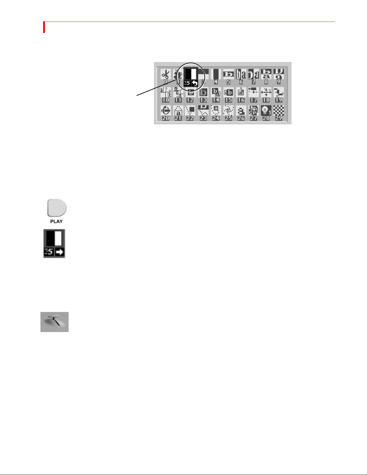
Automatic
Transitions
• Press PLAY. The MX-4 DV runs the transition at a pre-determined speed.
The MX-4 DV transitions between the two sources using the horizontal wipe transition with
the Output screen showing the results.
At the end of the wipe, B is on the OUTPUT monitor — it has become the CURRENT source. The
yellow highlight above the preview images has changed to reflect that. Furthermore, A is now the
NEXT source and the green highlight has been changed to A.
• To wipe back and forth between sources A and B, press PLAY repeatedly.
Speed
• To change the speed at which a transition runs, press the
cator under the transition icon changes.
• Press the button again until the desired speed appears. 0 is the slowest speed, 9 is the fastest.
• Try this with various speeds: Change the speed and press
Manual
Transitions
Use the TAKE BAR to run transitions and control their speed and direction.
•
Set up the transition as you would normally. However, instead of pressing PLAY, simply move
the
The transition begins running as soon as you move the
forth by moving the
Using CUT Transitions
SPEED button. The Speed indi-
PLAY.
T-BAR.
T-BAR. You can even move back and
T-BAR in different directions. Give it a try!
Most video productions use simple cuts a majority of the time. To cut between any two sources (for
example, you could cut from A to C to BACKGROUND to D), use the
There’s a quick way to cut back and forth between two sources using just the
of having to alternate between two
•
Press 0 and then OK to select transition 0, a simple cut.
CUT buttons:
CUT buttons.
PLAY button, instead
• Press PLAY again and again.
•
A solid color screen can be used as if it were a separate source. Press the NEXT/BACKGROUND
button and run any transition, or press CUT/BACKGROUND.
QUICK START CHOOSING T RANSITIONS
Choosing Transitions
The Preview screen contains the Transitions Menu. This menu contains icons and other information for all MX-4 DV transitions. A blue highlight indicates the transition selected for the next
transition.
Select Transitions in the following ways:
•
ARROW keys – Simply use the arrow keys to highlight the desired transition.
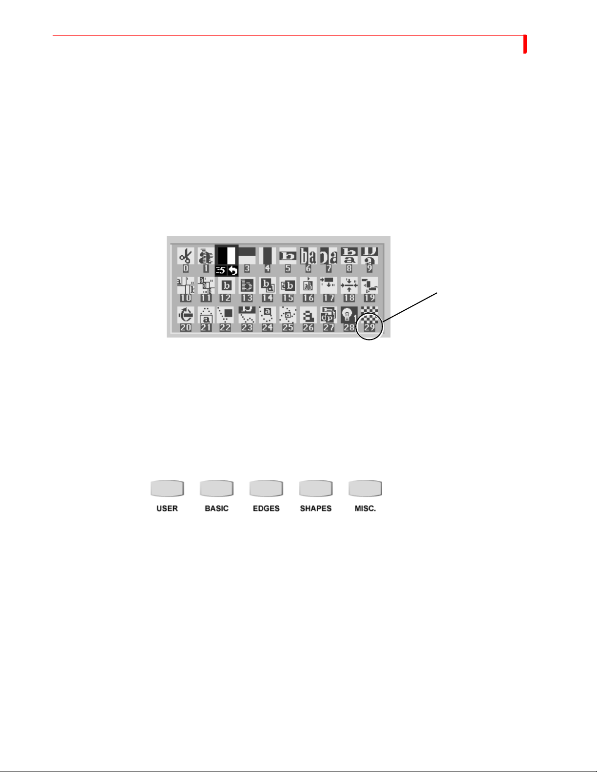
NUMBER keys – The MX-4 DV assigns a unique number to every transition. The number
appears below the transition icon on the PREVIEW screen (in the following example, the
checkerboard transition is number 29). You can use the number to select a transition. (When
you select/highlight a transition in the menu, the MX-4 DV shows the transition’s speed and
direction. At this point, the transition number is no longer visible.)
Transition Number 29
15
Enter 106 using the number keys (press 1, then 0, then 6), then press OK to highlight the tran-
•
sition icon.
The MX-4 DV replaces the current Transitions Menu and shows the one that contains the transition you selected.
•
Press PLAY.
Using Transition Categories
The MX-4 DV categorizes transitions into five major groups — User, Basic, Edges, Shapes, and
Misc. You can access any category at any time by pressing one of the Transition Category buttons.
When you press one of the buttons, the content of the Transitions Menu (see “The Preview Screen”
on page 11) changes.
• Press the
tion icons.
• Use the
• Press
The USER transition category is slightly different from the others. It originally contains a default
set of transitions, each of which also exists in the other categories. You can “tailor” the content of
the USER category to your specific needs and preferences. You’ll learn more about this in later
chapters.
PLAY or use the T-BAR to run the transition.
MISC. button. The Transitions Menu display a completely different set of transi-
ARROW keys to highlight a transition you’d like to see run.
Other Features
Refer to the rest of this User Guide to learn about the many additional MX-4 DV features, including:

16
MX-4 DV USER GUIDE CHAPTER 2
• Using the DEMO/DISPLAY button to change the content of the Preview screen.
• Freeze the picture, and compress it.
• Separately control the sound.
• Apply input effects, such as mosaic, paint (posterization), negative, and more.
• Use chromakey to combine parts of one picture with parts of another.
• Compose your own pictures, made up of several stills, color rectangles, and a moving picture.
• Rearrange the inputs so A, B, C, and D, and their audio channels come from different rear
panel jacks.
• Memorize a sequence of transitions and play them back.

CHAPTER 3
INSTALLING THE MX-4 DV
This chapter explains how to install (or, set up) MX-4 DV to use with other equipment.
Major topics include:
• Understanding Sources and Output
• Understanding Preview and Program monitors
• Understanding the MX-4 DV connectors
• Identifying Cables and Adapters you might need
• Installation examples
• Installing a Microphone
If you have experience with the Videonics MXPro DV, refer to APPENDIX E, Help for
MXPro DV Users, for information that will be helpful setting up your equipment.
18
MX-4 DV USER GUIDE CHAPTER 3
SOURCES AND OUTPUT
Source and Output refer to the way you use devices with MX-4 DV.
Source
Source
Source
Source
MX-4 DV
Output
Output
Source — A source is an input device. Each source provides a video signal, audio signal, or both.
You use the MX-4 DV to combine and (optionally) animate these signals.
Output — An output is a device on which you record and/or broadcast a signal. The signal might
contain video, audio, or both. This signal is often a mix of signals coming into MX-4 DV from one
or more sources. The output device might be a VCR with an optional monitor attached, or it might
be a live broadcast.
PREVIEW AND PROGRAM MONITORS
The MX-4 DV designates monitors as either Preview or Program to indicate how a particular mon-
itor may be used. This manual uses the following picture to distinguish between the two monitors.
INSTALLING THE MX-4 DV PREVIEW M ONITOR
Preview Monitor Program Monitor
Preview Monitor
The Preview monitor is your “working” monitor. Most of the time it contains controls for managing Source and Output devices. For example, it shows miniature versions of images coming from
the attached VCRs and camcorders. The Preview monitor also shows a menu of transitions and
other effects from which you can choose. Refer to “Using the Preview Screen” beginning on
page 35.
19
Program Monitor
The Program monitor shows the production exactly as recorded on the output device or displayed
in a live video environment. The Program monitor shows the program complete with transitions
and other effects. You normally connect the Program monitor to the output device. The Program
monitor can be either a Composite, or Y/C device.
Number of Monitors
You can operate the MX-4 DV with only one monitor connected to the Preview out. However, to
greatly simplify your work you should have at least two monitors — one Preview and one Program. Instructions in this manual assume you have separate Preview and Program monitors.
CAUTION
The preview monitor must be a Composite device. Do not attempt to connect any other type
of monitor to the PREVIEW OUT jack on the MX-4 DV rear panel.

20
MX-4 DV USER GUIDE CHAPTER 3
UNDERSTANDING MX-4 DV CONNECTORS
To properly setup the MX-4 DV, you need to know how and where to connect external components – such as VCRs, camcorders, and so forth. Use cables to connect video devices to the MX-4
DV’s rear panel. Refer to “Cables and Adapters” on page 22.
Remove the MX-4 DV from its package and set it so you can see the rear panel. Refer to the panel
and the illustration on the next page while reading this section.
The MX-4 DV rear panel has numerous connectors and they vary by type. You can connect input
sources in any combination – up to a maximum of twelve – but you can use a maximum of four
devices at any given time. You can process just the video signal from a device, just the audio signal, or both.
You can connect four separate output devices to the MX-4 DV. You might, for example, direct one
output to a recording device and another to a live broadcast.
Note the labels associated with each connector on the MX-4 DV rear panel.
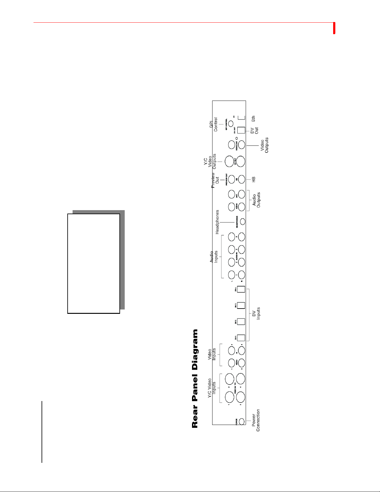
POWER — An electrical power connector. Use the power cord and adapter in the MX-4 DV
package to connect the unit to an electrical outlet.
Y/C IN— Connect Y/C sources to these connectors.
RCA IN — Connect composite sources to these connectors.
DV IN — Connect Digital Video sources to these connectors. Both the audio and video signal
is sent through these connections.
AUDIO IN — Connect audio devices to these connectors. Each set of connectors has L (Left)
and R (Right) jacks for stereo input. Refer to “Audio Connectors” on page 23.
HB IN — Connect a composite source such as a camera to lock on to and synchronize the
MX-4 DV with it.
GPI CONTROL — Connect a General Purpose Interface (GPI) device to this jack to control
the MX-4 DV from an external device or remote location. Refer to “Using a GPI Device”
beginning on page 120.
There are a total of eleven output connectors — one Preview, two composite, two S-Video, four
audio, and a Headphone jack.
PREVIEW OUT — Connect a composite video monitor to this jack. You cannot use an Y/C
monitor as Preview. This monitor serves as your visual “interface” with the MX-4 DV. It’s
where you do most of your work.
DV OUT — Connect a Digital Video output device. You record productions on this device,
use it to display a live broadcast signal or both. Both the audio and video signal are sent
through this connector.
Y/C OUT— Connect an Y/C output device. You record productions on this device, use it to
display a live broadcast signal, or both.
RCA OUT — Connect a composite output device. Same as above, but use this connector if
your output device is composite format.
AUDIO OUT — Connect a suitable audio cable or cables from these jacks to the audio inputs
on your output device. Refer to Chapter 12, Wo rk i n g wi t h A ud io , for a discussion of the dual
audio output features.
HEADPHONES — Refer to “Using Headphones” on page 25.
INSTALLING THE MX-4 DV UNDERSTANDING MX-4 DV CONNECTORS
21
MX-4 DV REAR PANEL
familiarize yourself with the
Please take a few moments to
connections on the MX-4 DV Rear
your equipment.
Panel before you begin setting up
22
MX-4 DV USER GUIDE CHAPTER 3
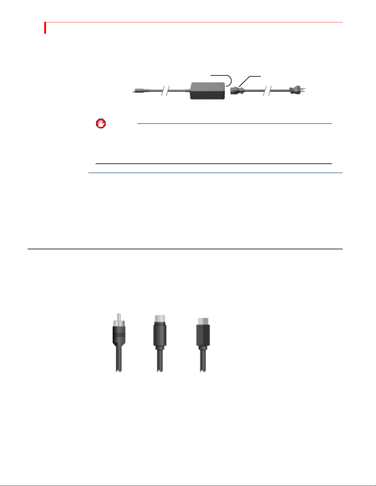
Power Connector
The MX-4 DV package contains the required transformer and power cord for the unit.
Male Socket Female Plug
Power
Adapter
Plug
Transformer Power Cord
WARNING
USE ONLY THE POWER CORD AND TRANSFORMER PROVIDED IN THE PACKAGE. DO NOT
USE THIS POWER CORD AND TRANSFORMER WITH ANY OTHER EQUIPMENT. FAILURE TO
OBSERVE THESE CONDITIONS CAN DAMAGE YOUR EQUIPMENT AND VOID YOUR
WARRANTY.
To connect the power cord and transformer:
1 Connect the female plug on the power cord into the male socket on the transformer.
2 Connect the male plug on the power cord to a suitable power outlet.
Male
Plug
3 Connect the power adapter plug on the transformer cord into the power connector on the MX-
4 DV rear panel.
4 Turn the MX-4 DV power switch (located on the right side of the unit) to the ON position.
CABLES AND ADAPTERS
To connect video devices to the MX-4 DV you need specific types of cables. You might also need
one or more adapters, depending on your equipment.
Look closely at the jacks on the MX-4 DV rear panel and note that they accept RCA Composite,
S-Video (Y/C), or Digital Video (DV)cables.
RCA
Composite
S-Video
(Y/C)
Digital Video
Connector
Before connecting any device to the MX-4 DV, make sure the cable you are using has the right
type of fitting for the jack you intend to use.
INSTALLING THE MX-4 DV CABLES AND A DAPTERS
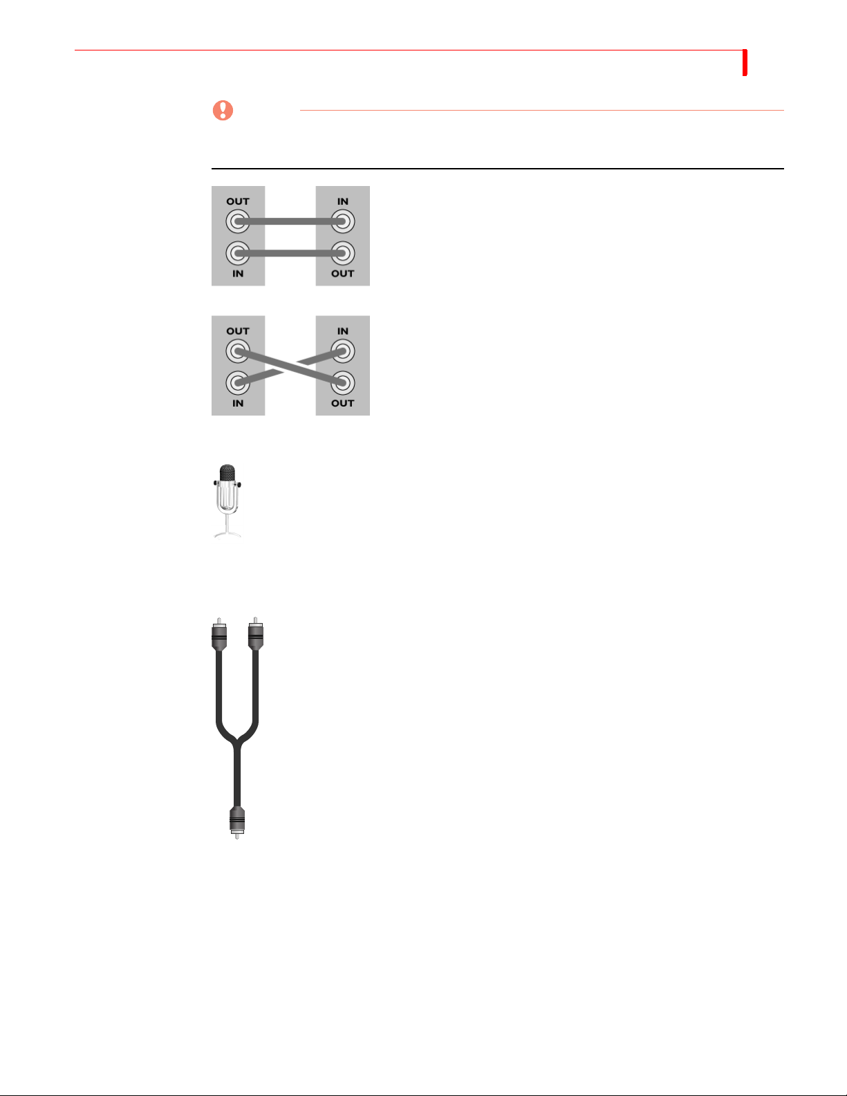
CAUTION
When making connections, always connect the OUT from one device to the IN on the other
device. NEVER connect OUT to OUT or IN to IN
GOOD!
BAD!
Microphones You can connect a microphone to any MX-4 DV input jack, but you may need a spe-
cial adapter to make the connection. The type of adapter needed varies depending on
the type of microphone you want to use. If you do not have the adapter you need,
take your microphone to a local electronics supply store to make sure you select the
correct adapter.
23
Audio Connectors To connect a stereophonic audio device to the MX-4 DV, you need two separate audio cables —
one for the left channel and one for the right.
To connect a monaural audio device you need a Y-adapter cable (like the one shown
at the left). Connect the single end of the adapter to the line input or output on the
device. Connect the two remaining ends to the left and right channel inputs or outputs on the MX-4 DV rear panel.
The Y-adapter cable does not provide stereophonic audio. It simply directs the mono
signal to or from both MX-4 DV channels.
You can also connect a mono audio device, then connect the other end to either the
left or right connector on any MX-4 DV audio input. Once connected, use the MX-4
DV ROUTE function to specify which connector (left or right you used. Refer to
“Route” beginning on page 73.
24
MX-4 DV USER GUIDE CHAPTER 3
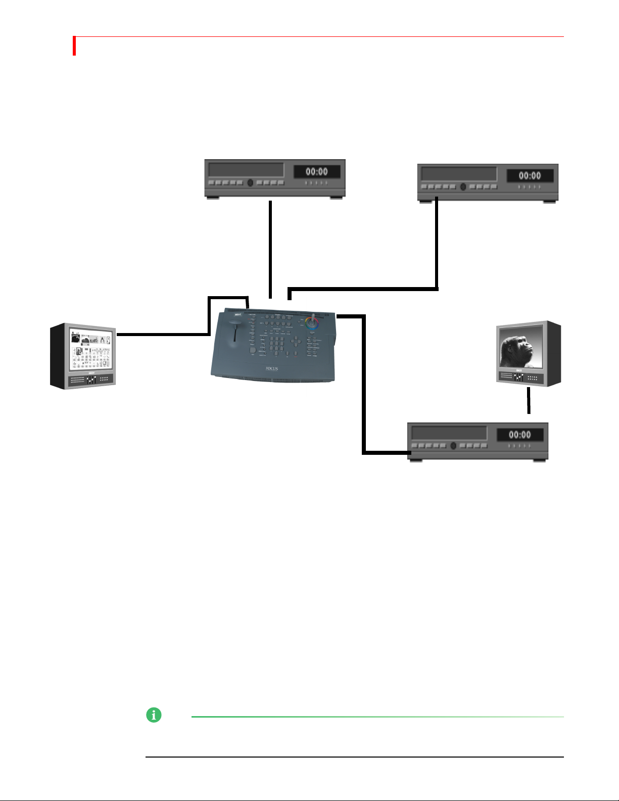
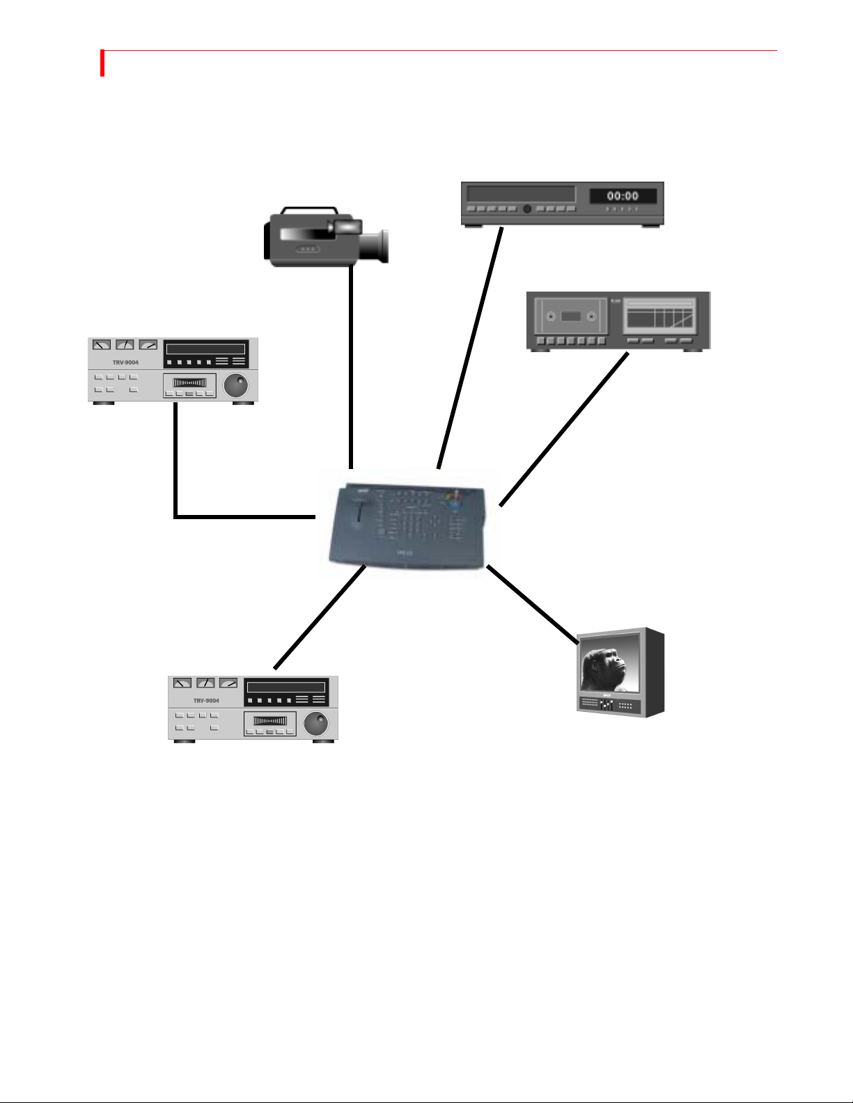
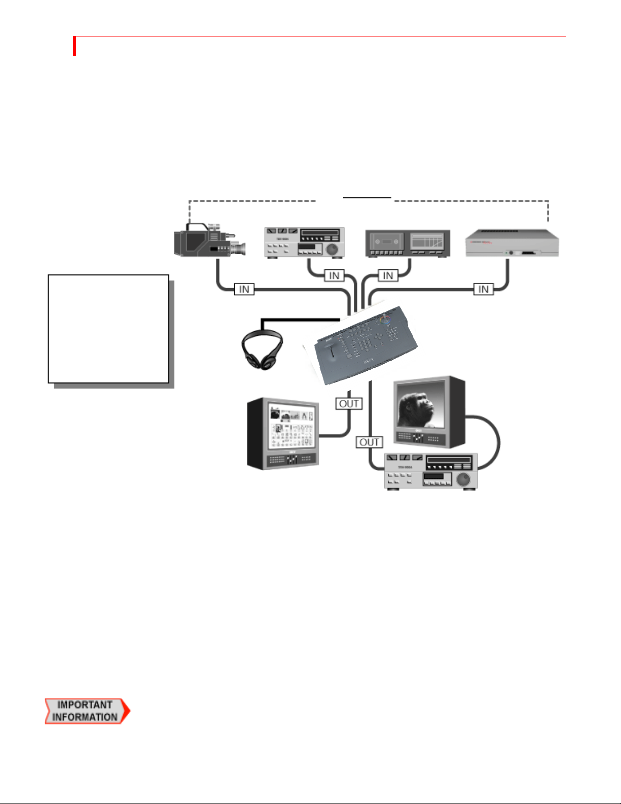
INSTALLATION EXAMPLES
This section shows examples of two common MX-4 DV configurations, but does not describe
every possibility. Before proceeding, study the following diagram (MX-4 DV Installation Concept)
that shows overall configuration concepts.
MX-4 DV Installation Concept
This diagram illustrates
the overall concept for
installing equipment with
MX-4 DV. Please study it
before you begin
installing your own
equipment.
Channel
Preview
Channel
A
B
SOURCES
Channel
C
Channel
D
Headphones
Program
You can have up to four separate audio/video input sources active at any given time. The MX-4
DV designates them as sources A, B, C, and D. You can use any mix of devices as necessary to
complete your work so long as they are valid MX-4 DV devices. For example, you can use VCRs,
VTR’s, camcorders, laserdisc players, satellite tuners, broadcast tuners/receivers, character generators (CG’s), video-equipped computers, and audio devices (such as a CD player or tape deck).
The MX-4 DV sends the output signal to a recording device (such as a VCR) and/or a Program
monitor.
Use a second monitor, Preview, to display preview images of all input sources. The Preview monitor also displays the on-screen controls you use to operate MX-4 DV. The Preview monitor is
required for operation.
Correlating Input Sources to MX-4 DV Jacks
As stated above, the MX-4 DV designates your input sources as A, B, C, and D. However, if you
examine the jacks on the MX-4 DV rear panel, you’ll see they are labeled 1, 2, 3, and 4. Initially,
there is a direct correlation between the letter and the number designations: jack 1 corresponds to
source A, jack 2 corresponds to source B, jack 3 corresponds to source C, and jack 4 to source D.
You can re-route inputs to other channels. For more information, refer to “Route” beginning on
page 73.
Output
INSTALLING THE MX-4 DV USING H EADPHONES
Using Headphones
To use headphones, connect them to the Headphone jack, which is located on the middle of the
unit. The jack accepts standard stereo headphones with a miniature plug. If your headphones have
a large plug, you need an adapter to switch it to a miniature plug.
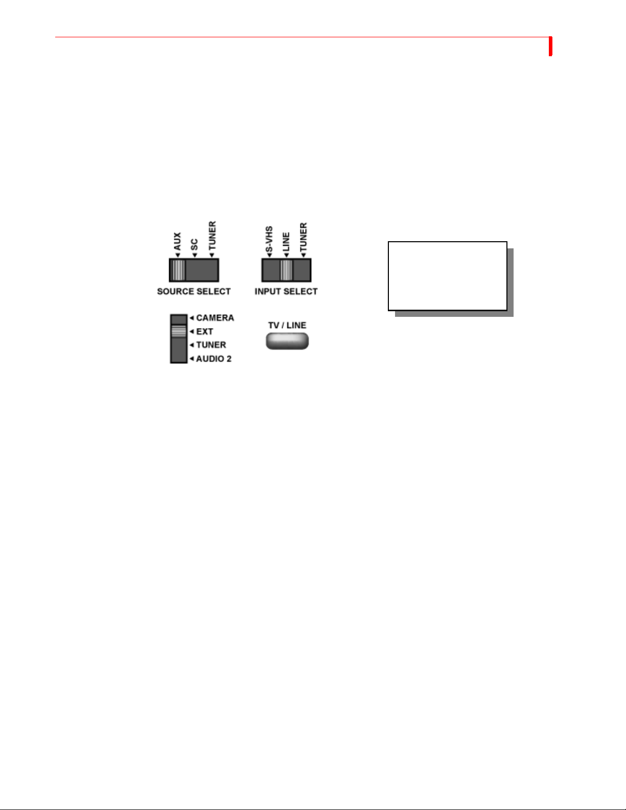
VCR Selector Switches
Many VCRs have an input selector switch that routes between Line (or AUX, EXT, A/V, or S) and
Tuner. Here are some examples.
If a device has a switch
similar to one of these,
set the switch to the
LINE position.
25
General Notes
Some VCRs have more than one VIDEO IN jack (for example, one might be Composite and the
other Y/C). Set the switch to match the jack you are using as the connector to the MX-4 DV.
When connecting video and audio outputs from source devices, most of the time you’ll probably
connect to corresponding jacks on the MX-4 DV rear panel. For example, if you connect the video
to the VIDEO IN jack labeled “1,” you’ll most likely connect the audio to the AUDIO IN jack also
labeled “1.” However, this is not a requirement. You might use non-corresponding jacks — for
example, you might connect the video from one source to VIDEO IN 1 but connect the audio from
the same source to AUDIO IN 2 if you want to control the audio and video separately.
Remember, DV devices carry the audio and video signal (as well as a machine control signal) on
the same connection.

26
MX-4 DV USER GUIDE CHAPTER 3
Post Production Configuration
This configuration is useful in a Post-Production environment—where you mix two or more programs together.
This installation example below shows the use of DV equipment in combination with analog
equipment.
1 Connect the VIDEO OUT from a DV VTR 1 to DV IN 1 on the MX-4 DV rear panel.
Connect the AUDIO OUTs from a DV VTR 1 to AUDIO IN 1 on the MX-4 DV rear panel.
2 Connect the VIDEO OUT from a DV VTR 2 to DV IN 2 on the MX-4 DV rear panel.
Connect the AUDIO OUTs from a DV VTR 2 to AUDIO IN 2 on the MX-4 DV rear panel.
3 OPTIONAL – Connect an audio source (CD player, tape deck, or microphone) to AUDIO IN
4 on the MX-4 DV rear panel.
4 Connect a Composite-type monitor to the PREVIEW OUT jack on the rear panel.
5 OPTIONAL - Connect a Character Generator (CG) to the OUT Y/C jack on the rear panel.
With this configuration you can superimpose titles from the CG atop the output signal.
6 Connect a recording VTR to the OUT Y/C jack on the rear panel.
If you are using the optional Character Generator (described above), connect the output from
the CG to the VTR input.
7 Connect an Output Monitor to the recording VTR so you can see the signal being recorded.
8 Connect the power cord and transformer to the MX-4 DV rear panel. Refer to “Power Connec-
tor” on page 22 for instructions.
Use the Route function (“Route” beginning on page 73) to make sure your devices are directed to
the correct MX-4 DV channels.
 Loading...