

FOCUS Enhancements Firefly SC User Manual

Firefly SC and MZ
Media Players
Version 3.2
User Manual

Trademarks
The Focus Enhancements, Visual Circuits, and Firefly logos are
registered trademarks in the United States and other countries. All
other products, services or company names mentioned herein are
claimed as trademarks and trade names by their respective
companies.
© Focus Enhancements (formerly Visual Circuits), 1999-2004.
All rights reserved. No portion of this manual may be copied by
any means without the prior consent of Visual Circuits.
Focus Enhancements
5155 East River Road, Suite 401
Minneapolis, MN 55421 USA
http://www.visualcircuits.com
Publication Number: 813-0049c
All specifications, notices and warnings are subject to change
without notice.

Firefly Safety Requirements
IMPORTANT SAFETY INSTRUCTIONS:
The following safety instructions apply to the
Visual Circuits Firefly:
1. Read and follow all warning notices and instructions marked on the
product or included in this manual. Opening or removing covers and/or
components may expose you to dangerous high voltage points or other
risks. Qualified personnel should perform all servicing.
2. The maximum ambient temperature for the Firefly is 114 degrees
Fahrenheit (45 degrees Celsius). Care should be given to allow sufficient
air circulation or space between units when Firefly is installed in a closed
or multi-unit rack assembly because the operating ambient temperature
of the rack environment must be greater than room ambient temperature.
3. Slots and openings in the cabinet (chassis) are provided for ventilation.
To ensure reliable operation of the product and to protect it from
overheating, maintain a minimum of 1-inch (2.5-cm) clearance on the top
and sides.
4. Installation of the Firefly in a rack without sufficient airflow can be
unsafe.
5. If installed in a rack, the rack should safely support the combined weight
of all equipment it supports. A fully loaded Firefly weighs 4 pounds (1.5
kg).
6. The connections and equipment of the Firefly should be capable of
operating safely with the maximum power requirements of the Firefly. In
the event of a power overload, the supply circuits and supply wiring
should not become hazardous.
7. External power supply AC power inputs are intended to be used with the
three-wire grounding type plug (a plug that has a grounding pin). This is
a safety feature. Equipment grounding is vital to ensure safe operation.
Do not defeat the purpose of grounding type plugs by modifying the plug
or using an adapter.
8. If a three-wire grounding type power source is not available, consult a
qualified electrician to determine another method of grounding the
equipment.
9. Install only in restricted areas in accordance with Articles 110-16, 100-17
and 110-18 of the National Electrical Code, ANSI/NFPA 70.
10. Do not allow anything to rest on the power cord and do not locate the
product where persons will walk on or come in contact with the power
cord.
i
POWER AND GROUND REQUIREMENTS:
Determine that the cumulative power requirements of the Firefly
plus other equipment in the rack do not overload the supply circuits
and/or wiring.
CAUTION
If using a power strip or similar supply, make sure
the power requirements of the chassis, plus the
cumulative power draw of any other equipment in
the rack, do not overload the supply circuit.
WARNING
For safe operation, this equipment must be properly
grounded.
The chassis should be reliably earth grounded to the
rack equipment. This earth ground connection must be
maintained when supply connection is other than direct
connection to the branch circuit.
ii

User Manual Regulatory Documentation
CAUTION
There is danger of explosion if the battery is
incorrectly replaced.
A lithium battery on the product provides backup power
for the device’s timekeeping capability. The battery has
an estimated life expectancy of ten years. When the
battery starts to weaken, the date and time may become
incorrect. If the battery fails, the unit must be sent back
to Visual Circuits for battery replacement.
WARNING
An improperly grounded power supply can result in
electrical shock.
The AC power cord provided with your system has a
grounded plug. Always use a grounded power cord with
a properly grounded wall outlet.
Class A Statement
FCC Part 15 (EN 61 00 0- 3 - 2 )
This equipment has been tested and found to comply with the
limits for a Class A digital device, pursuant to Part 15 (EN61000-3-
2) of the FCC Rules. These limits are designed to provide
reasonable protection against harmful interference when the
equipment is operated in a commercial environment. This
equipment generates, uses, and can radiate radio frequency
energy and, if not installed and used in accordance with this
instruction manual, may cause harmful interference to radio
communications. Operation of this equipment in a residential area
is likely to cause harmful interference in which case the user will
be required to correct the interference at his or her own expense.
The Firefly complies with Part 15 (EN61000-3-2) of the FCC rules.
iii

Operation is subject to the following two conditions:
1. This device may not cause harmful interference.
2. This device must accept any interference that may cause undesired
operation.
WARNING
Changes or modifications to this unit not expressly
approved by the party responsible for compliance
could void the user’s authority to operate the
equipment.
Industry Canada
This Class A digital apparatus meets all requirements of the
Canadian Interference-Causing Equipment Regulations.
Cet appareil numerique de la classe A respecte toutes les
exigences du Regulement sur le materiel brouilleur du Canada.
EMC and Safety Directive
Compliance
The CE mark is affixed to this Visual Circuits
Corporation product to confirm compliance with the following
European Community Directives:
Council Directive 89/336/EEC of 3 May 1989 on the approximation
of the laws of Member States relating to electromagnetic
compatibility.
And
Council Directive 73/23/EEC of 19 February 1973 on the
harmonization of the laws of Member States relating to electrical
equipment designed for use within certain voltage limits:
Each amended by Council Directive 93/68/EEC of 22 July 1993 on
the harmonization of CE marking requirements.
iv

Class A Warning (EN55024, EN55022)
In a domestic environment this product may cause radio
interference in which case the user may be required to take
adequate measures.
WARNING
Failure to provide adequate surge protection may
cause damage to the Firefly.
Visual Circuits does not warranty damage caused by
electrical surges to the system. Surge protection should
be provided when connecting any peripheral device and
power to the system.
v

vi

CONTENTS
Welcome to Firefly SC™ and MZ . . . . . . . . . . . . . . . . . . . . 1
Quick Start Plug and Play . . . . . . . . . . . . . . . . . . . . . . . . . 3
Before You Start, You Will Need. . . . . . . . . . . . . . . . . . . . . . . . . 3
Installation Sequence . . . . . . . . . . . . . . . . . . . . . . . . . . . . . . . . . 4
Install the Firefly . . . . . . . . . . . . . . . . . . . . . . . . . . . . . . . . . . . . . . . . 5
Configure for Network . . . . . . . . . . . . . . . . . . . . . . . . . . . . . . . . . . . . 7
Attaching a Laptop or PC . . . . . . . . . . . . . . . . . . . . . . . . . . . . . . 7
Ethernet . . . . . . . . . . . . . . . . . . . . . . . . . . . . . . . . . . . . . . . . 7
Serial . . . . . . . . . . . . . . . . . . . . . . . . . . . . . . . . . . . . . . . . . . 7
Changing TCP/IP Settings . . . . . . . . . . . . . . . . . . . . . . . . . . 8
WebView via Ethernet Port . . . . . . . . . . . . . . . . . . . . . . . . . 8
External Control Commands . . . . . . . . . . . . . . . . . . . . . . . . 9
Install Media Messenger . . . . . . . . . . . . . . . . . . . . . . . . . . . . . . . . . 10
Configure FTP . . . . . . . . . . . . . . . . . . . . . . . . . . . . . . . . . . . . . . . . . 11
Setup on-board Firefly FTP Server . . . . . . . . . . . . . . . . . . . . . . 11
Configure Firefly Properties . . . . . . . . . . . . . . . . . . . . . . . . . . . 11
Configuring the Firefly FTP Server . . . . . . . . . . . . . . . . . . . . . . 12
How To Create a Basic Playlist . . . . . . . . . . . . . . . . . . . . . . . . . . . . 13
Publish . . . . . . . . . . . . . . . . . . . . . . . . . . . . . . . . . . . . . . . . . . . . . . . 14
Via FTP . . . . . . . . . . . . . . . . . . . . . . . . . . . . . . . . . . . . . . . . . . 14
Via CD/DVD . . . . . . . . . . . . . . . . . . . . . . . . . . . . . . . . . . . . . . . 16
Software Updating . . . . . . . . . . . . . . . . . . . . . . . . . . . . . . . . . . . . . . 17
Encoding Requirements and Recommendations . . . . . 19
Encoding Requirements. . . . . . . . . . . . . . . . . . . . . . . . . . . . . . . . . . 19
Encoding Recommendations . . . . . . . . . . . . . . . . . . . . . . . . . . . . . . 20
WEBVIEW . . . . . . . . . . . . . . . . . . . . . . . . . . . . . . . . . . . . . . . 23
Accessing the WebView Interface . . . . . . . . . . . . . . . . . . . . . . . . . . 23
Setup Procedures: . . . . . . . . . . . . . . . . . . . . . . . . . . . . . . . . . . 23
Step 1: Connect to the Network. . . . . . . . . . . . . . . . . . . . . 23
Step 2: Determine the Address of the Firefly. . . . . . . . . . . 24
Step 3: Establishing Communication with the Firefly . . . . . 24
Step 4: Enter Your User Name and Password . . . . . . . . . 25
Forgot Name, Password, IP...???. . . . . . . . . . . . . . . . . . . . . . . 25
Using the WebView Interface. . . . . . . . . . . . . . . . . . . . . . . . . . . . . . 26
Transferring Media . . . . . . . . . . . . . . . . . . . . . . . . . . . . . . . . . . 27
Webview Software Update . . . . . . . . . . . . . . . . . . . . . . . . . . . . 30
vii

Contents
Reviewing, Previewing and Deleting Firefly Media . . . . . . . . . . 31
Reviewing Media and Storage Usage on the Firefly . . . . . 31
Previewing Videos and Graphic Overlays
on the Firefly . . . . . . . . . . . . . . . . . . . . . . . . . . . 32
Deleting Media from the Firefly . . . . . . . . . . . . . . . . . . . . . 33
Using the Playlist Editor . . . . . . . . . . . . . . . . . . . . . . . . . . . . . . 35
Creating a New Playlist . . . . . . . . . . . . . . . . . . . . . . . . . . . 36
Adding Videos to a Playlist . . . . . . . . . . . . . . . . . . . . . . . . 36
Removing Videos from a Playlist . . . . . . . . . . . . . . . . . . . . 36
Moving Videos Within a Playlist. . . . . . . . . . . . . . . . . . . . . 37
Shuffling Video Playback on a Channel. . . . . . . . . . . . . . . 37
Adding Graphic Overlays to a Playlist . . . . . . . . . . . . . . . . 37
Working With Graphic Overlays in a Playlist . . . . . . . . . . . 39
Adding Scrolling Text to a Playlist . . . . . . . . . . . . . . . . . . . 42
Working With Scrolling Text in a Playlist . . . . . . . . . . . . . . 43
Transparency Level . . . . . . . . . . . . . . . . . . . . . . . . . . . . . . 43
Saving a Playlist. . . . . . . . . . . . . . . . . . . . . . . . . . . . . . . . . 44
Playing a Playlist Quickly . . . . . . . . . . . . . . . . . . . . . . . . . . 45
Using the Schedule Editor. . . . . . . . . . . . . . . . . . . . . . . . . . . . . 46
Creating a New Schedule . . . . . . . . . . . . . . . . . . . . . . . . . 47
Adding an Event to a Schedule . . . . . . . . . . . . . . . . . . . . . 48
Deleting an Event from a Schedule . . . . . . . . . . . . . . . . . . 50
Editing an Event within a Schedule . . . . . . . . . . . . . . . . . . 50
Saving a Schedule. . . . . . . . . . . . . . . . . . . . . . . . . . . . . . . 52
Additional Saving and Loading Methods . . . . . . . . . . . . . . 53
Assigning Dates for Video Playback . . . . . . . . . . . . . . . . . 56
Exiting the Schedule Editor . . . . . . . . . . . . . . . . . . . . . . . . 58
Using the Player Control Panel. . . . . . . . . . . . . . . . . . . . . . . . . 59
Diagnostics . . . . . . . . . . . . . . . . . . . . . . . . . . . . . . . . . . . . . . . . 60
Diagnostics - General . . . . . . . . . . . . . . . . . . . . . . . . . . . . 61
Diagnostics - Video . . . . . . . . . . . . . . . . . . . . . . . . . . . . . . 62
Diagnostics - Playback. . . . . . . . . . . . . . . . . . . . . . . . . . . . 64
Diagnostics - Logging . . . . . . . . . . . . . . . . . . . . . . . . . . . . 65
System Settings . . . . . . . . . . . . . . . . . . . . . . . . . . . . . . . . . . . . 69
General Settings . . . . . . . . . . . . . . . . . . . . . . . . . . . . . . . . 69
Video Settings . . . . . . . . . . . . . . . . . . . . . . . . . . . . . . . . . . 71
Audio Settings . . . . . . . . . . . . . . . . . . . . . . . . . . . . . . . . . . 73
Control Settings . . . . . . . . . . . . . . . . . . . . . . . . . . . . . . . . 75
Network Settings . . . . . . . . . . . . . . . . . . . . . . . . . . . . . . . . 77
Logging Settings . . . . . . . . . . . . . . . . . . . . . . . . . . . . . . . . 82
WebView Settings . . . . . . . . . . . . . . . . . . . . . . . . . . . . . . . 85
FTP Auto-Update Settings. . . . . . . . . . . . . . . . . . . . . . . . . 87
HTTP Auto-Update Settings . . . . . . . . . . . . . . . . . . . . . . . 89
USB Devices . . . . . . . . . . . . . . . . . . . . . . . . . . . . . . . . . . . 91
viii

Contents
USB Devices Settings . . . . . . . . . . . . . . . . . . . . . . . . . . . . 92
USB Network Settings . . . . . . . . . . . . . . . . . . . . . . . . . . . . 94
Multicast. . . . . . . . . . . . . . . . . . . . . . . . . . . . . . . . . . . . . . . 96
Advanced Settings. . . . . . . . . . . . . . . . . . . . . . . . . . . . . . . 99
Networking. . . . . . . . . . . . . . . . . . . . . . . . . . . . . . . . . . . . 101
Overview . . . . . . . . . . . . . . . . . . . . . . . . . . . . . . . . . . . . . . . . . . . . 101
Getting Started . . . . . . . . . . . . . . . . . . . . . . . . . . . . . . . . . . . . . . . . 101
Media Messenger™ Software . . . . . . . . . . . . . . . . . . . . . . . . . . . . 102
Product Features: . . . . . . . . . . . . . . . . . . . . . . . . . . . . . . . . . . 102
Benefits: . . . . . . . . . . . . . . . . . . . . . . . . . . . . . . . . . . . . . . . . . 102
Updating Video Playback . . . . . . . . . . . . . . . . . . . . . . . . 103
Automatic Updating:. . . . . . . . . . . . . . . . . . . . . . . . . . . . . . . . . . . . 103
Manual Updating: . . . . . . . . . . . . . . . . . . . . . . . . . . . . . . . . . . . . . . 103
FTP UPDATING . . . . . . . . . . . . . . . . . . . . . . . . . . . . . . . . . . . . . 103
FTP Server. . . . . . . . . . . . . . . . . . . . . . . . . . . . . . . . . . . . 104
Player Management. . . . . . . . . . . . . . . . . . . . . . . . . . . . . 104
Creating a Firefly FTP Update Account . . . . . . . . . . . . . . 105
/ . . . . . . . . . . . . . . . . . . . . . . . . . . . . . . . . . . . . . . . . . . . . 105
/scripts . . . . . . . . . . . . . . . . . . . . . . . . . . . . . . . . . . . . . . . 105
/updates . . . . . . . . . . . . . . . . . . . . . . . . . . . . . . . . . . . . . . 105
FTP Update Process . . . . . . . . . . . . . . . . . . . . . . . . . . . . 106
FTP Updating Order. . . . . . . . . . . . . . . . . . . . . . . . . . . . . 107
FTP Font Files (.ttf) . . . . . . . . . . . . . . . . . . . . . . . . . . . . . 107
Playlist Parsing Routine. . . . . . . . . . . . . . . . . . . . . . . . . . 107
System Update Check . . . . . . . . . . . . . . . . . . . . . . . . . . . 108
Firefly Storage Cleanup Routine . . . . . . . . . . . . . . . . . . . 108
MULTICAST UPDATING. . . . . . . . . . . . . . . . . . . . . . . . . . . . . . . . 108
Overview . . . . . . . . . . . . . . . . . . . . . . . . . . . . . . . . . . . . . 109
Software Update Check. . . . . . . . . . . . . . . . . . . . . . . . . . 110
System Settings for Multicasting . . . . . . . . . . . . . . . . . . . 111
Manual Updating . . . . . . . . . . . . . . . . . . . . . . . . . . . . . . . . . . . . . . 112
WebView Updating . . . . . . . . . . . . . . . . . . . . . . . . . . . . . . . . . 112
Forgot Name, Password, IP...???. . . . . . . . . . . . . . . . . . . . . . 112
Direct File Access Updating . . . . . . . . . . . . . . . . . . . . . . . . . . 113
Log File Reporting . . . . . . . . . . . . . . . . . . . . . . . . . . . . . 115
Overview . . . . . . . . . . . . . . . . . . . . . . . . . . . . . . . . . . . . . . . . . . . . 115
Run Logs . . . . . . . . . . . . . . . . . . . . . . . . . . . . . . . . . . . . . . . . . . . . 116
Diagnostic Logs . . . . . . . . . . . . . . . . . . . . . . . . . . . . . . . . . . . . . . . 116
Log Format . . . . . . . . . . . . . . . . . . . . . . . . . . . . . . . . . . . . . . . 117
Run Logs . . . . . . . . . . . . . . . . . . . . . . . . . . . . . . . . . . . . . 117
ix

Contents
Diagnostic Logs . . . . . . . . . . . . . . . . . . . . . . . . . . . . . . . . 117
DTDs (Document Type Definition) . . . . . . . . . . . . . . . . . . 117
Log Default Playlist . . . . . . . . . . . . . . . . . . . . . . . . . . . . . . . . . 117
Maximum Log File Sizes. . . . . . . . . . . . . . . . . . . . . . . . . . . . . 117
Uploading Log Files . . . . . . . . . . . . . . . . . . . . . . . . . . . . . . . . 118
External Control Commands . . . . . . . . . . . . . . . . . . . . . 119
Connecting via RS232 . . . . . . . . . . . . . . . . . . . . . . . . . . . 119
Connecting via TCP/IP. . . . . . . . . . . . . . . . . . . . . . . . . . . 119
Basic Hyper Terminal Setup . . . . . . . . . . . . . . . . . . . . . . . . . . 120
VCC Control Commands:. . . . . . . . . . . . . . . . . . . . . . . . . . . . . . . . 121
Playlist Playback Commands . . . . . . . . . . . . . . . . . . . . . . . . . 121
Playing Individual Files . . . . . . . . . . . . . . . . . . . . . . . . . . . . . . 123
Using Serial Commands To Create Playlists . . . . . . . . . . . . . 130
. . . . . . . . . . . . . . . . . . . . . . . . . . . . . . . . . . . . . . . . . . . . . . . . 130
Firefly System Commands . . . . . . . . . . . . . . . . . . . . . . . . . . . 131
Callback Commands. . . . . . . . . . . . . . . . . . . . . . . . . . . . . . . . 132
Audio and Video Setting Changes . . . . . . . . . . . . . . . . . . . . . 133
Networking Commands. . . . . . . . . . . . . . . . . . . . . . . . . . . . . . 134
LDV Control Commands . . . . . . . . . . . . . . . . . . . . . . . . . . . . . . . . 141
Introduction . . . . . . . . . . . . . . . . . . . . . . . . . . . . . . . . . . . . . . . 141
COM Port Settings . . . . . . . . . . . . . . . . . . . . . . . . . . . . . . . . . 141
Error Codes. . . . . . . . . . . . . . . . . . . . . . . . . . . . . . . . . . . . . . . 142
Command Syntax . . . . . . . . . . . . . . . . . . . . . . . . . . . . . . . . . . 143
Address Arguments. . . . . . . . . . . . . . . . . . . . . . . . . . . . . . . . . 143
Command Summary . . . . . . . . . . . . . . . . . . . . . . . . . . . . . . . . 144
Playback Commands . . . . . . . . . . . . . . . . . . . . . . . . . . . . . . . 145
External Control Commands
Quick Reference Guide: . . . . . . . . . . . . . . . . . . . . . . . . . . . . . 159
VCC Commands:. . . . . . . . . . . . . . . . . . . . . . . . . . . . . . . 159
LDV Commands: . . . . . . . . . . . . . . . . . . . . . . . . . . . . . . . 159
Troubleshooting . . . . . . . . . . . . . . . . . . . . . . . . . . . . . . .161
General Issues . . . . . . . . . . . . . . . . . . . . . . . . . . . . . . . . . . . . . . . . 161
No Power to Firefly . . . . . . . . . . . . . . . . . . . . . . . . . . . . . . . . . 161
No Video Playback . . . . . . . . . . . . . . . . . . . . . . . . . . . . . . . . . 161
"Latent Images" or "Flashing" During Playback . . . . . . . . . . . 162
Stuttering Files During Playback. . . . . . . . . . . . . . . . . . . . . . . 162
Some files in the playlist do not play. . . . . . . . . . . . . . . . . . . . 163
Smooth Transitions . . . . . . . . . . . . . . . . . . . . . . . . . . . . . . . . . 164
SMPTE time codes are not recognized properly. . . . . . . . . . . 164
Filename Already Exists . . . . . . . . . . . . . . . . . . . . . . . . . . . . . 164
FTPing Font Files (.ttf) . . . . . . . . . . . . . . . . . . . . . . . . . . . . . . 164
x

Contents
Insufficient Disk Space . . . . . . . . . . . . . . . . . . . . . . . . . . . . . . 164
Forgot Name, Password, IP...???. . . . . . . . . . . . . . . . . . . . . . 165
Preventing Cabling and Connection Problems. . . . . . . . . . . . . . . . 166
Firefly Multi-Zone™ (MZ) . . . . . . . . . . . . . . . . . . . . . . . . 167
Installing the MZ . . . . . . . . . . . . . . . . . . . . . . . . . . . . . . . . . . . . . . 167
Video Output . . . . . . . . . . . . . . . . . . . . . . . . . . . . . . . . . . . . . . 167
Functionality . . . . . . . . . . . . . . . . . . . . . . . . . . . . . . . . . . . . . . . . . . 168
Software Update. . . . . . . . . . . . . . . . . . . . . . . . . . . . . . . . . . . . . . . 169
Status LED . . . . . . . . . . . . . . . . . . . . . . . . . . . . . . . . . . . . . . . 169
Using Firefly MZ to
Create a Layout and Playlist . . . . . . . . . . . . . . . . . . . . . . . . . . 170
Creating the Layout. . . . . . . . . . . . . . . . . . . . . . . . . . . . . . . . . 170
Setting Display Parameters . . . . . . . . . . . . . . . . . . . . . . . 170
Creating a MZ (multi-zone) Layout . . . . . . . . . . . . . . . . . 171
Position Zones in Layout Workspace. . . . . . . . . . . . . . . . 172
Creating the Playlist . . . . . . . . . . . . . . . . . . . . . . . . . . . . . . . . 173
Link the Playlist to the Firefly . . . . . . . . . . . . . . . . . . . . . . . . . 175
Firefly MZ Tips . . . . . . . . . . . . . . . . . . . . . . . . . . . . . . . . . . . . . . . . 177
Technical Specifications . . . . . . . . . . . . . . . . . . . . . . . . 181
Index. . . . . . . . . . . . . . . . . . . . . . . . . . . . . . . . . . . . . . . . . 183
xi

xii

WELCOME TO FIREFLY SC™ AND MZ
Thank you for purchasing the Firefly SC™ or the Firefly MZ™.
The Firefly SC and MZ are the media players developed
specifically for A/V professionals; combining the ease and
familiarity, flexibility and control of a disk-based, MPEG-2
decoder. These players provide for playlist creation, time/date
scheduling, graphic overlay capability, remote content updating,
network compatibility and a web-based “control and monitor”
interface.
In addition, the Firefly MZ when teamed with Media Messenger
software permits the creation of compelling multi-zone
presentations.
The Firefly SC and MZ belong to a new-generation of commercial
media players that fit into a wide variety of stand alone or network
attached applications, from trade shows and exhibitions to retail
merchandising, education and training, corporation
communications and digital signage.
The Firefly family continues to develop and evolve to meet the
evolving demands of A/V contractors.
Keep up with our latest product offerings by checking our web site
at www.visualcircuits.com.
1

Welcome to Firefly SC™ and MZ
Documentation Conventions
The Firefly SC and MZ are single-channel devices that share many
features and capabilities. Because of these similarities, this manual,
in general, does not differentiate between these two players and
simply calls them either the Firefly or the player. Thus, unless
specifically identified as belong to a particular player, the
information in this manual applies to both.
Information specific only to the MZ is found in the section, Firefly
Multi-Zone™ (MZ) on page 167.
Notes
An exclamation point indicates information found in a Note.
2
QUICK START PLUG AND PLAY
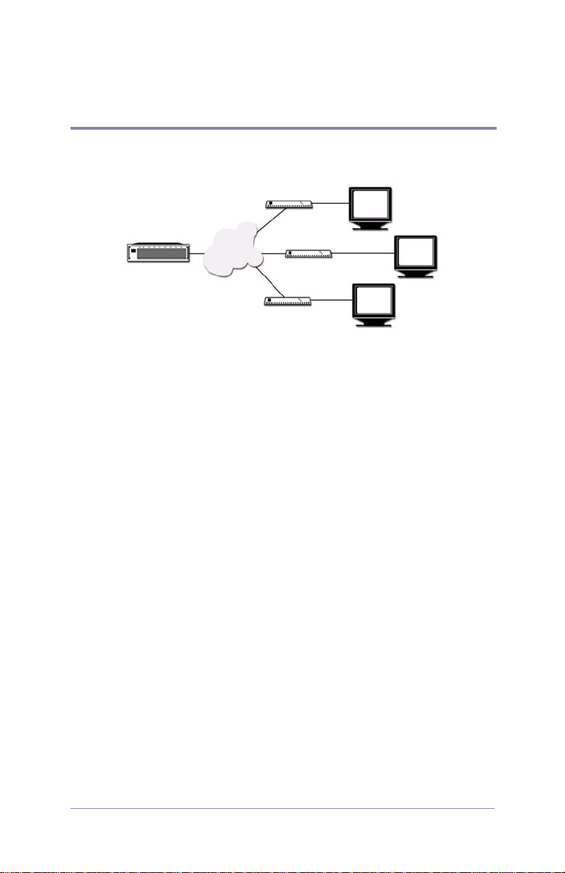
The Firefly is a single-channel output device that is simple to configure and can reside on a network or stand alone.
LAN
Content Server
Firefly Players
Display Devices
Before You Start, You Will Need
Have the following items ready before installing the Firefly MZ
Media Player.
• BNC Video cables
• IP and FTP Information
IP Addressing Mode (Static or DHCP)
IP Address
Hostname
FTP Proxy IP Address and Port
FTP Username and Password
3

Quick Start Plug and Play
Installation Sequence
1. Install Firefly on network.
a. Connect your video and audio cables to the back of the
Firefly.
b. Connect the video and audio cables from the Firefly to the
inputs on the monitor and audio component.
c. Connect the power cable to the back of the Firefly and plug
it in to your power source.
d. At start up, the Firefly runs through a a short series of self-
diagnostics before beginning automated playback.
The Firefly comes loaded with sample videos that are useful
as you become familiar with Firefly’s features and for
diagnostic purposes. Video playback is typically controlled
through a “playlist” that defines which videos are played
and in what order. Only one playlist can be active at any
time, though any number of playlists can be stored on
Firefly for later use. Whenever Firefly is turned on, the
playlist that was last used is reloaded and playback begins
automatically.
The default active playlist for a new Firefly is called
“factory.fpl”. The fastest way to test Firefly is to simply
plug it in, connect the cables and turn it on.
The Firefly’s default factory setting plays component,
1080i, and line-level audio. If your application requires the
Firefly to employ a different video standard and/or video
output type, use Webview to change the system settings
as needed. See the section on Video Settings on page 71
for more information.
2. Configure Firefly for network, see page 7.
3. Install Media Messenger application, refer to Media Messenger
User Manual for details.
4. Configure FTP.
5. Creating a Layout and Playlist.
6. Publishing via FTP or CD/DVD.
4
Install the Firefly
Quick Start Plug and Play
10/100
DVI-I
Network
Component
Pb Pr Y
S-Video
Y C
Composite
Power
12 VDC
1 2 3 4 5 6
-
+
Unbalanced
(Left Right)
+
USB
-
+
Serial
-
Digital
S / PDIF
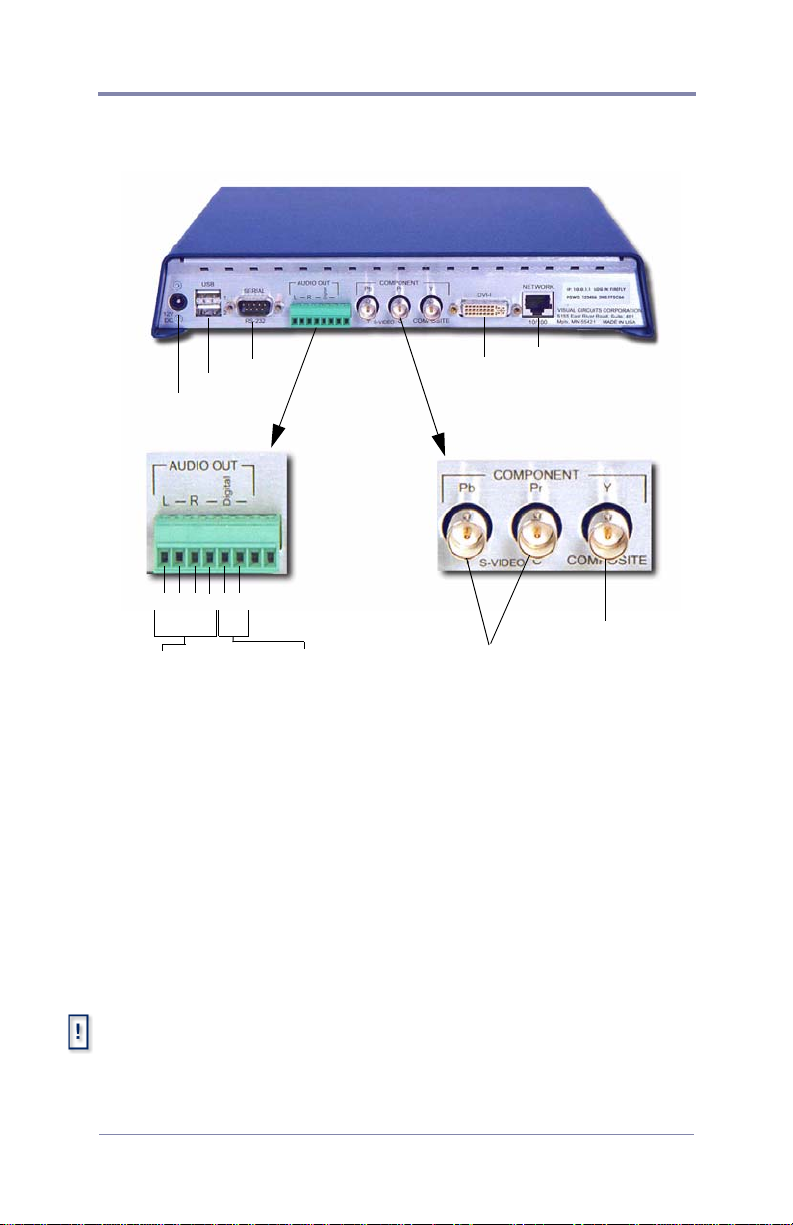
1. Attach the video cables to the Firefly.
❏ For Composite monitors: Connect a BNC-ended
composite cable (not included) to the composite connector
on the back of the Firefly.
❏ For S-Video monitors: Connect a BNC-ended Y s-video
cable (not included) to the corresponding chroma (C) and
luma (Y) connectors on the back of the Firefly.
❏ For Component monitors: Connect BNC-ended
component cables (not included) to the corresponding Pr, Y
and Pb connectors on the back of the Firefly.
MZ RGB and Component Output
For best quality video or to putput to an anology display device, it is
necessary to use the MZ’s DVI output anlog with a DVI to VGA adapter,
see for more details.
5

Quick Start Plug and Play
2. Attach the audio cables to the Firefly.
❏ For an unbalanced audio connection use audio cables with
stranded wire ends and connect to terminal 1 (Left +),
terminal 4 (Right +), and terminals 2 and 4 (designated
grounds).
❏ If unbalanced audio cable lengths exceed 10 meters, use an
Audio Line Amp/Balancer such as the Radio Design Labs,
Stick On.
❏ For a S/PDIF digital audio, use a stranded audio cables and
connect to terminal 5 Digital Audio (+) and terminal 6 (-).
3. Attach video and audio cables to the video and audio inputs on
the video monitor and audio component.
4. Cable the Firefly to the network.
5. Plug in the power supply and attach the power cable to the
Firefly. The Firefly powers up and performs a short series of
self-diagnostics and then begins automated playback
6
Quick Start Plug and Play
Configure for Network
Often, the Firefly TCP/IP defaults must change to accommodate
the network where it will reside. The best method is to attach a
computer to the media player.
Contact the Network Administrator for the correct network configuration
information,
Attaching a Laptop or PC
Before beginning, verify that the computer and/or the Firefly are powered
off. When connections are completed, power on the devices.
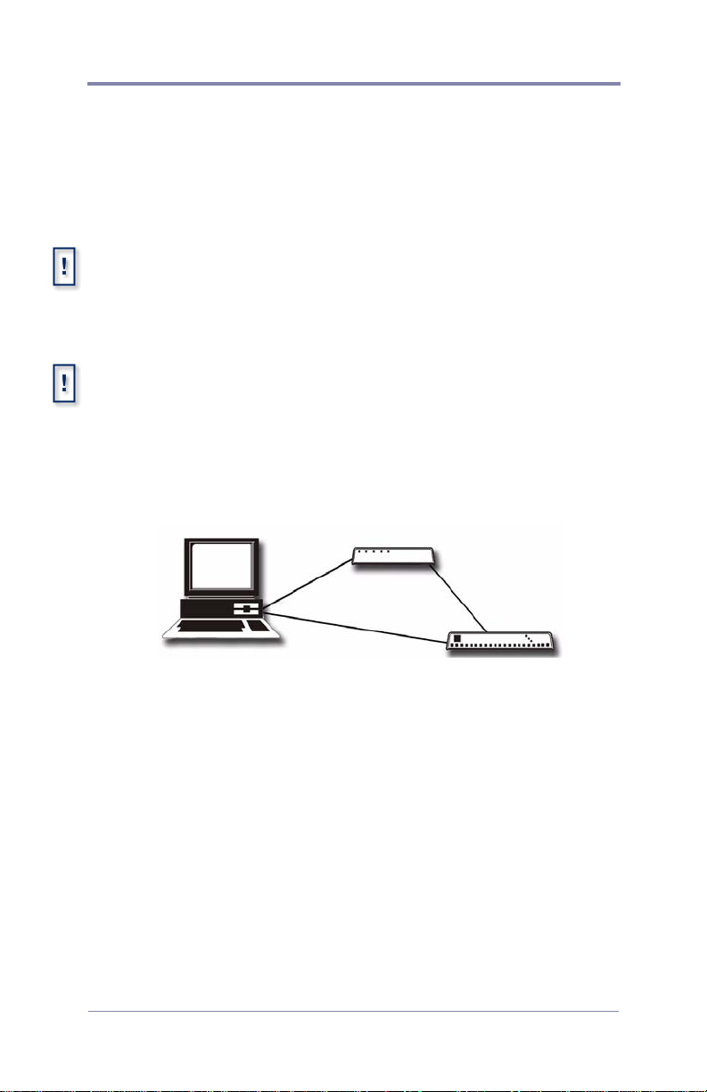
Ethernet
❏ Connect the computer directly to the Firefly using an
Ethernet crossover cable.
or
Ethernet via Hub or Switch.
Ethernet via Cross-over Cable.
❏ Connect using standard Ethernet cables and a hub or switch.
Serial
Use a null modem cable, female DB-9 to female DB-9, RS232
cable, when connecting to the Firefly via the serial port.
7

Quick Start Plug and Play
Changing TCP/IP Settings
Firefly default TCP/IP settings:
Static IP Address: 10.0.1.1
Login (case sensitive): firefly
Password: 123456
There are two methods for initially changing the Firefly TCP/IP
settings: WebView and serial commands.
WebView via Ethernet Port
WebView is a browser-based, administration tool-kit that resides
on the Firefly.
1. Set your PC’s IP address to a number in the same range as the
Firefly, such as 10.0.1.2.
2. Open a browser and enter the default IP address 10.0.1.1 in the
address field.
3. Access WebView using the default Firefly login and password,
shown above.
4. Set the IP address and other TCP/IP parameters as required.
5. Click on Update Settings to save.
6. Click on Player Control.
7. Click on Restart Player.
This initializes the new settings.
8

Quick Start Plug and Play
Restarting the Firefly is only necessary when updating the network
settings in a DHCP environment, i.e. going from Static to DHCP mode,
changing the Host Name, and so on. .
External Control Commands
External control commands require that the computer has an ASCII
generating control program, such as Hyper Terminal. The
parameters are:
• Serial port 1
• 9600 Bps
• Echo typed letters locally
Use the following Visual Circuits commands to configure the
Firefly.
FireflySetIpAddress
Syntax
fireflysetipaddr IP Address
FireflySetNetmask
Syntax
fireflysetnetmask netmask
FireflySetGateway
Syntax
fireflysetgateway gateway
FireflySetNetworkType
Syntax
fireflysetnetworktype 1 (DHCP) or 2 (Static)
Filenames and External Commands
When using external commands to handle files, it is necessary for those
files to have names without, i.e. sales_video.mpg not sales video.mpg.
One convention is to use underscores in place of spaces.
For more information about External Control Commands see,
External Control Commands on page 119, and for network
configuration, see Network Settings on page 77.
9

Quick Start Plug and Play
Install Media Messenger
Install Visual Circuit’s Media Messenger software from the Media
Messenger CD by following the online screens and prompts. Refer
to the Media Messenger User Manual for details.
Whenever the installation sequence requests the Company Name or
Registration Key, enter the name and key precisely as Visual Circuits
provided it.
10
Quick Start Plug and Play
Configure FTP
Setup on-board Firefly FTP Server
• Configure Firefly properties.
• Configure Firefly FTP server.
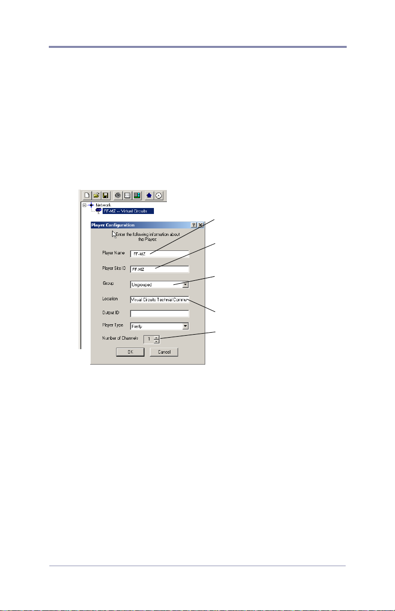
Configure Firefly Properties
Unique name to identify player
(Host Name)
Unique ID set in player before
installation, Media Messenger
uses it to identify the player.
If player belongs to a group,
select the group name fromlist.
Physical location of the player.
Set to one for Firefly.
1. Open the Main window of Media Messenger.
2. Right-click in the Firefly object in the Network Pane and
display Player drop down menu.
3. Click on Properties to display Player Configuration.
4. Fill in the Player Configuration fields.
11
Quick Start Plug and Play
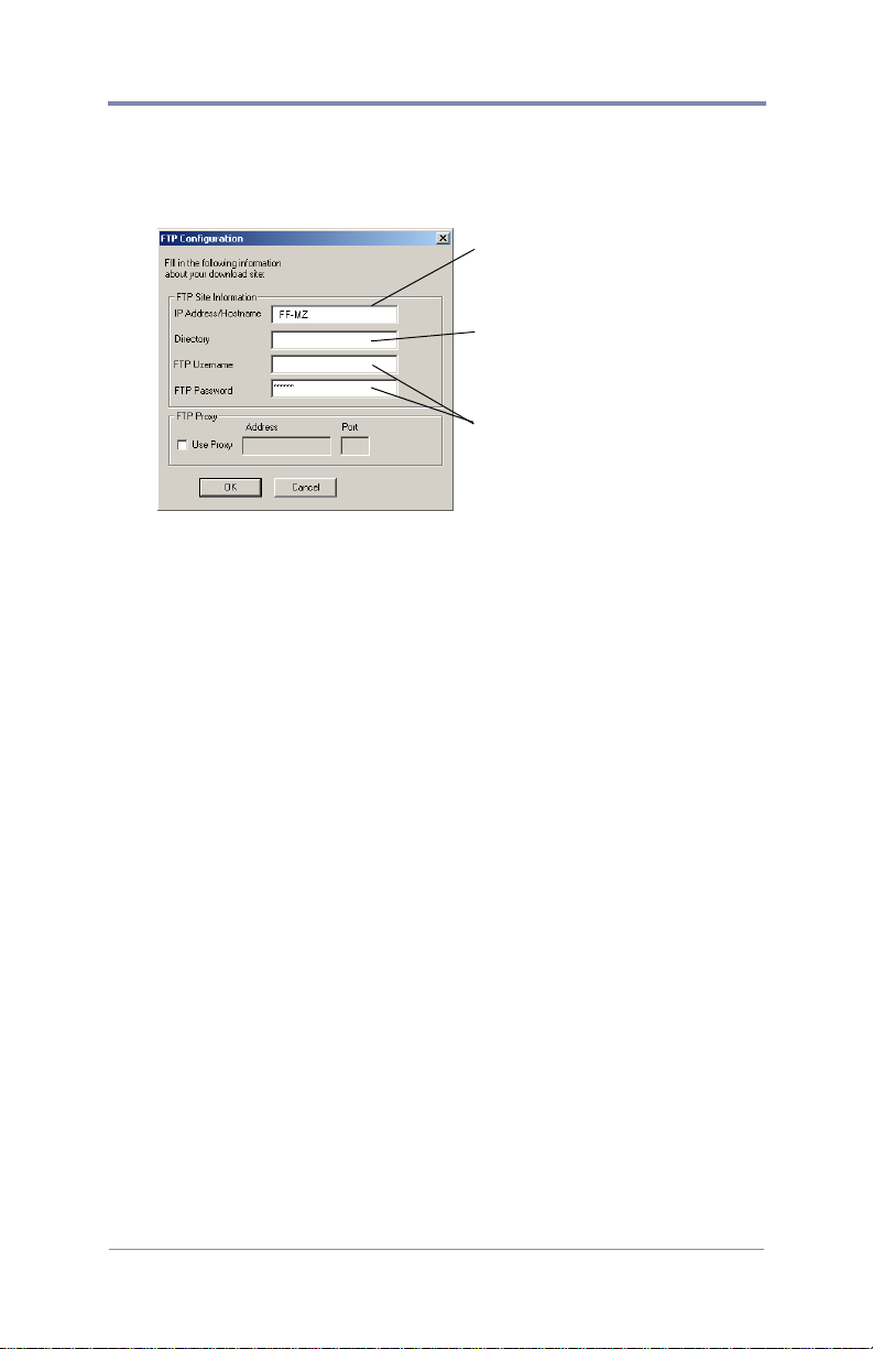
Configuring the Firefly FTP Server
Network Administrator provides FTP configuration information.
This may be the Firefly or an
FTP server used for storing
presentation content.
When loading directly to Firefly, leave the Directory field
blank and place files in FTP
root directory.
Security settings provided by
Network Administrator.
1. Click on Settings in the Main Menu list and select FTP Server
Setup.
2. Fill in the FTP Site Information Fields.
a. IP Address/Hostname.
Network Administrator provides the IP Address and
Hostname of the FTP server.
b. Directory
Name of the directory where the files go.
c. FTP UserName
d. FTP Password
3. FTP Proxy
Check this box if using a FTP Proxy server, then add its IP
address and port.
For additional information, see Updating Video Playback on
page 103.
12

Quick Start Plug and Play
How To Create a Basic Playlist
Playing media on Firefly requires
1. That the MPEG videos reside on the Firefly.
2. That a valid playlist resides on the Firefly.
There are several methods for creating a layout and playlist for the
Firefly.
1. WebView interface program (see Using the Playlist Editor on
page 35).
2. Media Messenger, refer to its user manual.
3. Firefly MZ, which is an optional enhancement that works with
Media Messenger, see
and Playlist on page 170.
Using Firefly MZ to Create a Layout
13
Quick Start Plug and Play
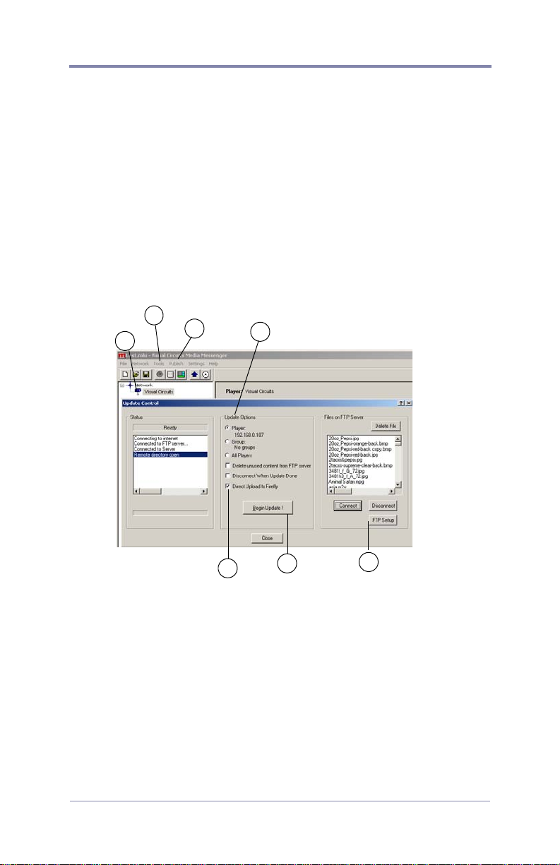
Publish
Via FTP
1. Open WebView, click on System Settings, and select Network.
Confirm that the network and security settings are correct.
2. Return to the Media Messenger main workspace.
3. Select the target player or player group in the Network Pane.
4. Click on Publish in the Media Messenger, Main Menu List and
then select Publish to FTP.
2
3
4
6
6A
7
5
5. Confirm that the Media Messenger FTP configuration is
correct for the player: click on the FTP Setup button and
review setup data.
14

Quick Start Plug and Play
6. Select the Upload Option:
a. a specific player,
b. a group of players,
c. all players,
6A If uploading to one specific Firefly, select the Direct
Upload to Firefly option, otherwise leave unchecked.
7. Click Begin Update button.
When the upload completes, close the Update Control window.
The Firefly MZ loads immediately and begins playing back the
playlist. If using a schedule, the playback begins at the appropriate
time.
15
Quick Start Plug and Play
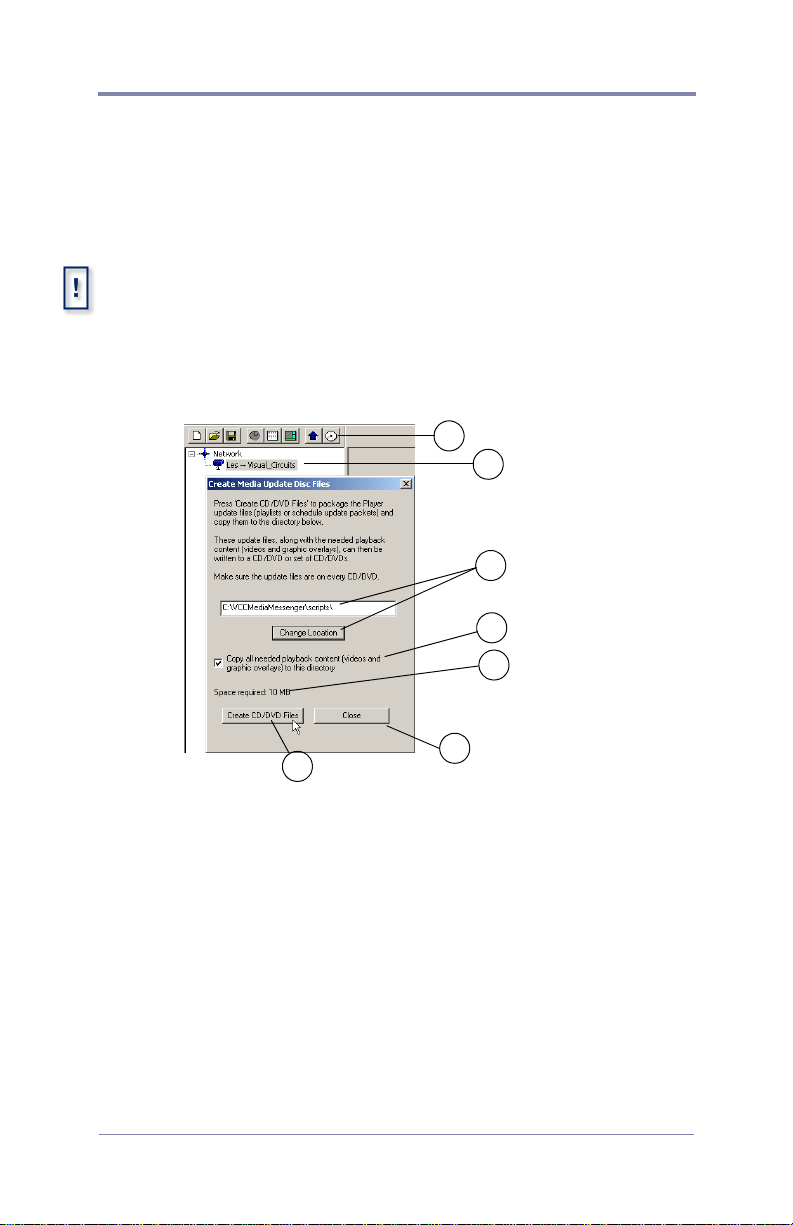
Via CD/DVD
Another method of transporting playlists, schedules, and media
files is to create a media update disc.This process creates the
content image of an autorun disc (CD/DVD).
Media Messenger does not burn a CD or DVD. It prepares the
necessary files so that when they are burned on to a disc, an
autorun application is created.
1. Go to the Media Messenger main workspace and select the
player or group that is to receive the update.
2
1
3
4
5
6
7
2. Select the Publish to CD/DVD icon.
3. Verify that the correct destination for the files is shown in the
destination field: change if necessary.
4. Check the Copy All Needed ... box.
5. Verify that the total space required does not exceed the
capacity of the CD or DVD disc.
6. Click on Create CD/DVD Files.
7. Click on Close.
8. Use CD/DVD creation application to burn files on a disc.
16
 Loading...