

FOCUS Enhancements DR-DV5000 User Manual
DV Video Disk Recorder
USER GUIDE
DR-DV5000

PAGE 1
FireStore DR-DV5000 User Guide
WARNING: TO PREVENT FIRE OR
SHOCK HAZARD, DO NOT EXPOSE
THIS EQUIPMENT TO RAIN OR
MOISTURE.
IMPORTANT NOTICE
(For U.S.Model)
The serial number for this equipment is located
on the bottom of the unit. Please write this serial
number on your enclosed warranty card and
keep it in a secure area. This is for your security.
CAUTION:
This product satisfies FCC regulations when
shielded cables and connectors are used to
connect the unit to other equipment. To prevent
electromagnetic interference with electric
appliances such as radios and televisions, use
shielded cables and connectors for connections.
NOTE:
This equipment has been tested and found
to comply with the limits for a Class A
digital device, pursuant to Part 15 of the
FCC Rules. These limits are designed to
provide reasonable protection against harmful
interference in a residential installation.
This equipment generates, uses, and can
radiate radio frequency energy and, if not
installed and used in accordance with the
instructions, may cause harmful interference
to radio communications. However, there is
no guarantee that interference will not
occur in a particular installation. If this
equipment does cause harmful interference
to radio or television reception,which can
be determined by turning the equipment off
and on, the user is encouraged to try to
correct the interference by one or more
of the following measures:
• Reorient or relocate the receiving
antenna.
• Increase the separation between the
equipment and receiver.
• Connect the equipment into an outlet
on a circuit different from that to
which the receiver is connected.
• Consult the dealer or an experienced
radio/TV technician for help.
INFORMATION TO USER
Alteration or modifications carried out
without appropriate authorization may
invalidate the user’s right to operate
the equipment.
CAUTION:
• Use of controls or adjustments or
performance of procedures other than
those specified herein may result in
hazardous radiation exposure.
• The use of optical instruments with
this product will increase eye hazard.
THE ON/OFF SWITCH IS SECONDARY
CONNECTED AND THEREFORE DOES
NOT SEPARATE THE UNIT FROM
MAINS POWER IN STANDBY
POSITION.
CAUTION: TO PREVENT ELECTRIC
SHOCK, DO NOT USE A (POLARIZED) PLUG
WITH AN EXTENSION CORD, RECEPTACLE
OR OTHER OUTLET UNLESS THE BLADES
CAN BE FULLY INSERTED TO PREVENT
BLADE EXPOSURE.
ATTENTION: POUR PREVENIR LES
CHOCS ELECTRIQUES NE PAS UTILISER
CETTE FICHE POLARISEE AVEC UN
PROLONGATEUR, UNE PRISE DE COURANT
OU UNE AUTRE SORTIE DE COURANT,
SAUF SI LES LAMES PEUVENT ETRE
INSEREES A FOND SANS EN LAISSER
AUCUNE PARTIE A DECOUVERT.
FireStore DR-DV5000 User Guide
Please read through these operating instructions so you will know how to operate your model
properly. After you have finished reading the instructions, put them away in a safe place for
future reference.
FireStore DR-DV5000 User Guide
IMPORTANT
CAUTION:
TO PREVENT THE RISK OF
ELECTRIC SHOCK, DO NOT
REMOVE COVER (OR BACK).
NO USER SERVICEABLE PARTS
INSIDE.REFER SERVICING TO
QUALIFIED SERVICE PERSONNEL.
The exclamation point within an
equilateral triangle is intended to alert
the user to the presence of important
operating and maintenance (servicing)
instructions in the literature accompanying
the appliance.
READ INSTRUCTIONS – All the safety and
operating instructions should be read before the
product is operated.
RETAIN INSTRUCTIONS – The safety and
operating instructions should be retained for
future reference.
HEED WARNINGS – All warnings on the product
and in the operating instructions should be
adhered to.
FOLLOW INSTRUCTIONS – All operating and use
instructions should be followed.
CLEANING – Unplug this product from the wall
outlet before cleaning. The product should be
cleaned only with a polishing cloth or a soft dry
cloth. Never clean with furniture wax, benzine,
insecticides or other volatile liquids since they
may corrode the cabinet.
ATTACHMENTS – Do not use attachments not
recommended by the product manufacturer as
they may cause hazards.
WATER AND MOISTURE – Do not use this
product near water – for example, near a bathtub,
wash bowl, kitchen sink, or laundry tub; in a wet
basement; or near a swimming pool; and the like.
ACCESSORIES – Do not place this product on an
unstable cart, stand, tripod, bracket or table. The
product may fall, causing serious injury to a child
or an adult, and serious damage to the product.
Use only with a cart, stand, tripod, bracket or
table recommended by the manufacturer, or sold
with the product. Any mounting of the product
should follow the manufacturer’s instructions, and
should use a mounting accessory recommended
by the manufacturer.
CART – A product and cart combination should be
moved with care. Quick stops, excessive force,
and uneven surfaces may cause the product and
cart combination to overturn.
VENTILATION – Slots and openings in the cabinet
are provided for ventilation and to ensure reliable
operation of the product and to protect it from
overheating, and these openings must not be
blocked or covered. The openings should never be
blocked by placing the product on a bed, sofa, rug,
or other similar surface. This product should not be
placed in a built-in installation such as a bookcase
or rack unless proper ventilation is provided or the
manufacturer’s instructions have been adhered to.
POWER SOURCES – This product should be
operated only form the type of power source
indicated on the marking label. If you are not sure of
the type of power supply to your home, consult
your dealer or local power company.
LOCATION – The appliance should be installed in
a stable location.
NON-USE PERIODS – The power cord of the
appliance should be unplugged from the outlet
when left unused for a long period of time.
GROUNDING OR
POLARIZATION –
• If this product is equipped with a polarized
alternating current line plug ( a plug having one
blade wider than the other), it will fit into the
outlet only one way. This is a safety feature. If
you are unable to insert the plug fully into the
outlet, try reversing the plug. If the plug should
still fail to fit, contact your electrician to replace
your obsolete outlet. Do not defeat the safety
purpose of the polarized plug.
• If this product is equipped with a three-wire
grounding type plug, a plug having a third
(grounding) pin, it will only fit into a grounding
type power outlet. This is a safety feature. If you
are unable to insert the plug into the outlet,
contact your electrician to replace your obsolete
outlet. Do not defeat the safety purpose of the
grounding type plug.
POWER-CORD PROTECTION – Power supply cords
should be routed so that they are not likely to be
walked on or pinched by items placed upon or
against them, paying particular attention to cords at
plugs, convenience receptacles, and the point where
they exit the product.
OUTDOOR ANTENNA GROUNDING – If an outside
antenna or cable system is connected to the
product, be sure the antenna or cable system is
grounded so as to provide some protection against
voltage surges and built-up static charges. Article
810 of the National Electric Code, ANSI/NFPA 70,
provides information with regard to proper
grounding of the mast and supporting structure,
grounding of the lead-in wire to an antenna
discharge unit, size of grounding connectors,
location of antenna discharge unit, connection to
grounding electrodes, and requirements for the
grounding electrode. See Fig. A.
LIGHTNING – For added protection for this product
during a lightning storm, or when it is left unattended
and unused for long periods of time, unplug it from
the wall outlet and disconnect the antenna or cable
system. This will prevent damage to the product due
to lightning and power-line surges.
POWER LINES – An outside antenna system
should not be located in the vicinity of overhead
power lines or other electric light or power
circuits, or where it can fall into such power lines
or circuits. When installing an outside antenna
system, extreme care should be taken to keep
from touching such power lines or circuits as
contact with them might be fatal.
OVERLOADING – Do not overload wall outlets,
extension cords, or integral convenience
receptacles as this can result in a risk of fire or
electric shock.
OBJECT AND LIQUID ENTRY – Never push
objects of any kind into this product through
openings as they may touch dangerous voltage
points or short-out parts that could result in a fire
or electric shock. Never spill liquid of any kind on
the product.
SERVICING – Do not attempt to service this
product yourself as opening or removing covers
may expose you to dangerous voltage or other
hazards. Refer all servicing to qualified service
personnel.
DAMAGE REQUIRING SERVICE – Unplug this
product from the wall outlet and refer servicing to
qualified service personnel under the following
conditions:
• When the power-supply cord or plug is damaged.
• If liquid has been spilled, or objects have fallen
into the product.
• If the product has been exposed to rain or water.
• If the product does not operate normally by
following the operating instructions. Adjust
only those controls that are covered by the
operating instructions as an improper
adjustment of other controls may result in
damage and will often require extensive work
by a qualified technician to restore the product
to its normal operation.
• If the product has been dropped or damaged in
any way.
• When the product exhibits a distinct change in
performance – this indicates a need for service.
REPLACEMENT PARTS – When replacement parts
are required, be sure the service technician has
used replacement parts specified by the
manufacturer or have the same characteristics as
the original part. Unauthorized substitutions may
result in fire, electric shock or other hazards.
SAFETY CHECK – Upon completion of any service
or repairs to this product, ask the service
technician to perform safety checks to determine
that the product is in proper operating condition.
WALL OR CEILING MOUNT – The product should
not be mounted to a wall or ceiling.
HEAT – The product should be situated away from
heat sources such as radiators, heat, registers,
stoves or other products (including amplifiers)
that produce heat.
CAUTION
RISK OF ELECTRIC SHOCK
DO NOT OPEN
IMPORTANT SAFETY INSTRUCTIONS
ELECTRIC
SERVICE
EQUIPMENT
GROUND
CLAMP
ANTENNA
LEAD IN WIRE
ANTENNA
DISCHARGE UNIT
(NEC SECTION 810-20)
GROUNDING CONDUCTORS
(NEC SECTION 810-21)
NEC — NATIONAL ELECTRICAL CODE
GROUND CLAMPS
POWER SERVICE GROUNDING
ELECTRODE SYSTEM
(NEC ART 250. PART H)
Fig A
PAGE 3
FireStore DR-DV5000 User Guide

FOCUS Enhancements, Inc. warrants
this product against defects in materials
or workmanship as follows:
For a period of TWO years from the date
of purchase, FOCUS Enhancements, Inc.
will repair or replace the unit, at our option,
without charge for parts or labor. After the
period of TWO years, you must pay all
parts and labor charges.
The limited warranty is extended only to
the original purchaser. It does not cover
damage or failure caused by or attributable
to Acts of God, abuse, misuse, improper or
abnormal usage, faulty installation, improper
maintenance, lightning, or other incidences of
excessive voltage, or any repairs or tampering
by other than a FOCUS Enhancements
authorized repair facility. It does not cover
replacement of batteries or other consumable
parts, transportation costs or damage in
transit. This warranty will become void if the
serial number or model number identification
has been wholly or partially removed or
erased. Repair or replacement under the
terms of this warranty do not extend the
terms of this warranty. This warranty can
not be modified by an agent of FOCUS
Enhancements, Inc. unless in written and
signed by an officer of FOCUS
Enhancements, Inc.
Should this product prove defective in
workmanship or material, the consumer’s
sole remedies shall be such repair or
replacement provided by the terms of
this warranty. Under no circumstances shall
FOCUS Enhancements, Inc. be liable for
any loss or damage, direct, consequential, or
incidental, arising out of the use of or inability
to use this product. Some states do not allow
limitations on how long an implied warranty
lasts or the exclusions or limitations of
incidental or consequential damages, so the
above limitations or exclusions may not apply
to you. This warranty gives you specific legal
rights. You may also have other rights which
vary from state to state.
For customers outside the USA or Canada,
please contact your dealer or distributor
for repairs or technical support. Refer to
document MANL-0907-XX for a list of
International Dealers and Authorized Service
Centers.
In the United States or Canada, to obtain
warranty service, call or write the FOCUS
Enhancements, Inc. Technical Support Line
for a Return Material Authorization (RMA)
number. Technical Support can be reached at:
Email: support@FOCUSinfo. com
Telephone: 408-370-9963. 8AM-5PM,
Monday to Friday (PST)
(Hint: Mondays tend to be the busiest)
Fax: 408-866-4859
Address: FOCUS Enhancements, Inc.
1370 Dell Ave.
Campbell, CA. 95008
Please mark the RMA number clearly on
the outside of the package. Include a copy
of your sales receipt, a brief description of the
symptoms, your name, address, phone number
and any special shipping instructions. Then
deliver or ship the product, postage and shipping
costs prepaid, to a FOCUS Enhancements
authorized repair facility. For the name of
the nearest repair facility, contact FOCUS
Enhancements, Inc. Technical Support.
PAGE 4
FireStore DR-DV5000 User Guide

PAGE 5
FireStore DR-DV5000 User Guide
Table of Contents . . . . . . . . . . . . . . . . . . . . . . . . . . . . . . . . . . . . . . . . .PAGE
Warning and Safety Information . . . . . . . . . . . . . . . . . . . . . . . . . . . . . . . . . . . . . . . . . . . . . . . .1
Statement of Compliance . . . . . . . . . . . . . . . . . . . . . . . . . . . . . . . . . . . . . . . . . . . . . . . . . . . . .3
Statement of Warranty . . . . . . . . . . . . . . . . . . . . . . . . . . . . . . . . . . . . . . . . . . . . . . . . . . . . . . . .4
Introduction . . . . . . . . . . . . . . . . . . . . . . . . . . . . . . . . . . . . . . . . . . . . . . . . . . . . . . . .7
PACKAGE CONTENTS . . . . . . . . . . . . . . . . . . . . . . . . . . . . . . . . . . . . . . . . . . . . . . . . . . . . . .7
WHAT IS A DTE DISK RECORDER? . . . . . . . . . . . . . . . . . . . . . . . . . . . . . . . . . . . . . . . . . . .7
WHAT IS FIRESTORE DR-DV5000? . . . . . . . . . . . . . . . . . . . . . . . . . . . . . . . . . . . . . . . . . . . .7
BASIC APPLICATIONS . . . . . . . . . . . . . . . . . . . . . . . . . . . . . . . . . . . . . . . . . . . . . . . . . . . . . .8
MOUNTING TO A CAMCORDER . . . . . . . . . . . . . . . . . . . . . . . . . . . . . . . . . . . . . . . . . . . . .9
INSERTING AND REMOVING FIRESTORE FSHDD-1 FIREWIRE DRIVES . . . . . . . . . . .11
USING EXTERNAL FIREWIRE DISK DRIVES . . . . . . . . . . . . . . . . . . . . . . . . . . . . . . . . . .12
Physical Features . . . . . . . . . . . . . . . . . . . . . . . . . . . . . . . . . . . . . . . . . . . . . . . . . .12
FRONT PANEL . . . . . . . . . . . . . . . . . . . . . . . . . . . . . . . . . . . . . . . . . . . . . . . . . . . . . . . . . . .12
LCD DISPLAY . . . . . . . . . . . . . . . . . . . . . . . . . . . . . . . . . . . . . . . . . . . . . . . . . . . . . . . . . . .13
FRONT PANEL BUTTONS . . . . . . . . . . . . . . . . . . . . . . . . . . . . . . . . . . . . . . . . . . . . . . . . . .15
REAR CONNECTOR PANEL . . . . . . . . . . . . . . . . . . . . . . . . . . . . . . . . . . . . . . . . . . . . . . . .17
DR-DV5000 Menus And Functions . . . . . . . . . . . . . . . . . . . . . . . . . . . . . . . . . . . . .18
RECORD MODE MENU . . . . . . . . . . . . . . . . . . . . . . . . . . . . . . . . . . . . . . . . . . . . . . . . . . .18
Normal Record . . . . . . . . . . . . . . . . . . . . . . . . . . . . . . . . . . . . . . . . . . . . . . . . . . . . . . . . . .19
Retro Disk Record . . . . . . . . . . . . . . . . . . . . . . . . . . . . . . . . . . . . . . . . . . . . . . . . . . . . . . .19
Retro Cache Record . . . . . . . . . . . . . . . . . . . . . . . . . . . . . . . . . . . . . . . . . . . . . . . . . . . . . .20
Snap . . . . . . . . . . . . . . . . . . . . . . . . . . . . . . . . . . . . . . . . . . . . . . . . . . . . . . . . . . . . . . . . .21
Time Lapse . . . . . . . . . . . . . . . . . . . . . . . . . . . . . . . . . . . . . . . . . . . . . . . . . . . . . . . . . . . . .21
Dump To Tape . . . . . . . . . . . . . . . . . . . . . . . . . . . . . . . . . . . . . . . . . . . . . . . . . . . . . . . . . .21
Dump To Disk . . . . . . . . . . . . . . . . . . . . . . . . . . . . . . . . . . . . . . . . . . . . . . . . . . . . . . . . . .21
PLAY MODE MENU . . . . . . . . . . . . . . . . . . . . . . . . . . . . . . . . . . . . . . . . . . . . . . . . . . . . . .22
Play Clip . . . . . . . . . . . . . . . . . . . . . . . . . . . . . . . . . . . . . . . . . . . . . . . . . . . . . . . . . . . . . . .22
Loop Clip . . . . . . . . . . . . . . . . . . . . . . . . . . . . . . . . . . . . . . . . . . . . . . . . . . . . . . . . . . . . . .22
Loop All . . . . . . . . . . . . . . . . . . . . . . . . . . . . . . . . . . . . . . . . . . . . . . . . . . . . . . . . . . . . . . .22
Play All . . . . . . . . . . . . . . . . . . . . . . . . . . . . . . . . . . . . . . . . . . . . . . . . . . . . . . . . . . . . . . .22
CONTROL MODE MENU . . . . . . . . . . . . . . . . . . . . . . . . . . . . . . . . . . . . . . . . . . . . . . . . . .22
Local . . . . . . . . . . . . . . . . . . . . . . . . . . . . . . . . . . . . . . . . . . . . . . . . . . . . . . . . . . . . . . . . .22
AV/C . . . . . . . . . . . . . . . . . . . . . . . . . . . . . . . . . . . . . . . . . . . . . . . . . . . . . . . . . . . . . . . . .23
Syncro Slave . . . . . . . . . . . . . . . . . . . . . . . . . . . . . . . . . . . . . . . . . . . . . . . . . . . . . . . . . . . .23
Series Record . . . . . . . . . . . . . . . . . . . . . . . . . . . . . . . . . . . . . . . . . . . . . . . . . . . . . . . . . . .23
Split Slaved . . . . . . . . . . . . . . . . . . . . . . . . . . . . . . . . . . . . . . . . . . . . . . . . . . . . . . . . . . . .24
HDD BYPASS . . . . . . . . . . . . . . . . . . . . . . . . . . . . . . . . . . . . . . . . . . . . . . . . . . . . . . . . . . . .24
RECORD FORMAT MENU . . . . . . . . . . . . . . . . . . . . . . . . . . . . . . . . . . . . . . . . . . . . . . . . .25

FireStore DR-DV5000 User Guide
PAGE 6
SETUP MENU . . . . . . . . . . . . . . . . . . . . . . . . . . . . . . . . . . . . . . . . . . . . . . . . . . . . . . . . . . . .25
HDD Port . . . . . . . . . . . . . . . . . . . . . . . . . . . . . . . . . . . . . . . . . . . . . . . . . . . . . . . . . . . . . .26
Date Format . . . . . . . . . . . . . . . . . . . . . . . . . . . . . . . . . . . . . . . . . . . . . . . . . . . . . . . . . . . .26
Set Date & Time . . . . . . . . . . . . . . . . . . . . . . . . . . . . . . . . . . . . . . . . . . . . . . . . . . . . . . . . .26
Operating System Version No. . . . . . . . . . . . . . . . . . . . . . . . . . . . . . . . . . . . . . . . . . . . . . .27
Operating System Upgrade . . . . . . . . . . . . . . . . . . . . . . . . . . . . . . . . . . . . . . . . . . . . . . . . .27
Cam Type . . . . . . . . . . . . . . . . . . . . . . . . . . . . . . . . . . . . . . . . . . . . . . . . . . . . . . . . . . . . . .28
Timecode Mode . . . . . . . . . . . . . . . . . . . . . . . . . . . . . . . . . . . . . . . . . . . . . . . . . . . . . . . . .28
Timecode, User Bit & Drop/Non-Drop Preset . . . . . . . . . . . . . . . . . . . . . . . . . . . . . . . . . . .29
Infrared Sensor Setting . . . . . . . . . . . . . . . . . . . . . . . . . . . . . . . . . . . . . . . . . . . . . . . . . . . .29
GPI Settings . . . . . . . . . . . . . . . . . . . . . . . . . . . . . . . . . . . . . . . . . . . . . . . . . . . . . . . . . . . .30
LCD Back Light Settings . . . . . . . . . . . . . . . . . . . . . . . . . . . . . . . . . . . . . . . . . . . . . . . . . .30
Clip Preview Settings . . . . . . . . . . . . . . . . . . . . . . . . . . . . . . . . . . . . . . . . . . . . . . . . . . . . .30
Audio Correct Settings . . . . . . . . . . . . . . . . . . . . . . . . . . . . . . . . . . . . . . . . . . . . . . . . . . . .31
UTILITIES MENU . . . . . . . . . . . . . . . . . . . . . . . . . . . . . . . . . . . . . . . . . . . . . . . . . . . . . . . .31
Organize Keeper Clips . . . . . . . . . . . . . . . . . . . . . . . . . . . . . . . . . . . . . . . . . . . . . . . . . . . .31
Organize OMF Clips . . . . . . . . . . . . . . . . . . . . . . . . . . . . . . . . . . . . . . . . . . . . . . . . . . . . . .32
Delete Clip . . . . . . . . . . . . . . . . . . . . . . . . . . . . . . . . . . . . . . . . . . . . . . . . . . . . . . . . . . . . .32
Format Disk . . . . . . . . . . . . . . . . . . . . . . . . . . . . . . . . . . . . . . . . . . . . . . . . . . . . . . . . . . . .32
Partition Volume . . . . . . . . . . . . . . . . . . . . . . . . . . . . . . . . . . . . . . . . . . . . . . . . . . . . . . . . .33
Repair Disk . . . . . . . . . . . . . . . . . . . . . . . . . . . . . . . . . . . . . . . . . . . . . . . . . . . . . . . . . . . .33
File Name . . . . . . . . . . . . . . . . . . . . . . . . . . . . . . . . . . . . . . . . . . . . . . . . . . . . . . . . . . . . . .34
Factory Reset . . . . . . . . . . . . . . . . . . . . . . . . . . . . . . . . . . . . . . . . . . . . . . . . . . . . . . . . . . .34
Getting Firestore Recorded Clips Onto A Computer System . . . . . . . . . . . . . . . .35
Mounting Firewire Disk Drives To Windows XP, 2000,
98SE And ME Computer Systems . . . . . . . . . . . . . . . . . . . . . . . . . . . . . . . . . . . . . . . . . . .36
Using Firestore DR-DV5000 Recorded Avid OMF Clips On Avid Xpress DV. . . . . . . . . . . .36
Dismounting Firewire Disk Drives Fro38m Windows XP, 2000,
98SE and ME Computer Systems . . . . . . . . . . . . . . . . . . . . . . . . . . . . . . . . . . . . . . . . . . . .38
Mounting Firewire Disk Drives To Macintosh Computer Systems . . . . . . . . . . . . . . . . . . . .38
Dismounting Firewire Disk Drives From Macintosh Computer Systems . . . . . . . . . . . . . . .38
DR-DV5000 Remote Control Commanders . . . . . . . . . . . . . . . . . . . . . . . . . . . . . . .39
T
echnical Specifications . . . . . . . . . . . . . . . . . . . . . . . . . . . . . . . . . . . . . . . . . . . . .40
DR-D
V5000 Record And Control LCD And Camcorder
Viewfinder Display Modes . . . . . . . . . . . . . . . . . . . . . . . . . . . . . . . . . . . . . . . . . . .41
Notes
. . . . . . . . . . . . . . . . . . . . . . . . . . . . . . . . . . . . . . . . . . . . . . . . . . . . . . . . . . . .42

INTRODUCTION
Thank you for purchasing the Focus
Enhancements FireStore DR-DV5000 DTE
DV Video Disk Recorder for JVC full-size DV
camcorders. DR-DV5000 adds a digital disk
recorder/player for a powerful acquisition
combination.
The purpose of this User Guide is to explain
the features and operation of the FireStore
DR-DV5000. You have also received a DRDV5000 QuickStart guide which should be
kept for quick future reference. Please study
the contents of this User Guide before
attempting to use your DR-DV5000.
Check the Focus Enhancements website
regularly for updates to software and
documentation and if you have questions
or require further assistance with your
FireStore DR-DV5000, please visit:
www.focusinfo.com/support
Alternatively, contact your Focus
Enhancements or JVC FireStore
dealer/distributor.
PACKAGE CONTENTS
Please take a moment to study the contents of
your FireStore DR-DV5000 package. You
should have the following contents:
• One (1) FireStore DR-DV5000 Unit w/ two
(2) captive screws
• One (1) FireStore FSHDD-1 FireWire Hard
Disk Drive (HDD)*
• One (1) Hardwire Remote Commander
• One (1) Infrared Remote Commander
• One (1) 6-pin to 4-pin Right Angle
FireWire cable.
• One (1) 3.5mm to DB9 Serial Cable
• One (1) Battery Gasket
• One (1) GY-DV500/-550/-700 Adapter Plate
w/ four (4) mount screws
• User Guide CD-ROM
• QuickStart Guide
If any of these contents are missing, please
contact Focus Enhancements or your JVC
FireStore dealer/distributor immediately.
You may need to purchase cables to connect
more than one hard disk drive to FireStore
DR-DV5000 at a time. Your Focus Enhancements
dealer can help you identify additional cables
you may need.
* Depending on the model number that is
ordered, drive capacity may vary. Please verify
that you have received the correct FireStore
FSHDD-1 capacity that you ordered.
WHAT IS A DTE DISK RECORDER?
A DTE DV Disk Recorder is a device that
allows you to record/playback DV video
directly to/from a removable FireWire hard
disk drive without using a computer. Video is
input or output as a DV Video Stream through
FireStore which writes/reads a DV data stream
in NLE native file formats from/to a FireWire
hard disk drive.
WHAT IS FIRESTORE DR-DV5000?
FireStore DR-DV5000 is a DTE DV Disk
Recorder that mounts directly to JVC Full
Size DV camcorders. With DR-DV5000, it is
possible to:
• Input or output DV video from/to JVC DV
camcorders such as the GY-DV5000, DV500,
DV550 and DV700. It is also possible to use it
stand-alone with virtually any DV video device
FireStore DR-DV5000 User Guide
PAGE 7

• Capture clips to hard disk at the acquisition
stage - there is no need to capture later.
• Simultaneously record to disk while
recording to your camcorder's tape
• Record clips to disk in DTE Technology
based “edit-ready” file formats such as Raw
DV, AVI Type 1, AVI Type 2, Matrox AVI,
Canopus AVI, QuickTime and Avid DV-OMF.
This means clips are immediately available to
your NLE system without first having to
transfer or convert the clips.
• Connect your FireWire disk directly to your
computer or connect via FireStore which
allows mount and dismount of the drives
without re-cabling or computer re-boots.
• Jump from clip to clip without spooling
through tape when in playback mode.
• As well as video, record and playback
embedded DV audio in either 2-ch (16-bit,
48kHz) or 4-ch (12-bit, 32kHz) formats.
• Record source timecode from your camcorder
or create your own Free Run, Regen or Rec
Run timecode. It is also possible to preset
timecode and user-bit values.
• Record, play and navigate using FireStore
DR-DV5000’s VTR style controls.
• Record and recall a single frame of DV
video. Also record user definable time-lapse
sequences.
• Slow playback down or speed it up by 1
frame per second increments.
• Use trick playback modes such as up to
30X/-30X fast-forward and rewind speeds,
reverse play, loop clip and loop entire disk.
• Control DR-DV5000 remotely via FireWire
(for triggering record/pause or AV/C) from a
DV based camcorder GPI port. Alternatively,
control DR-DV5000 via RS-232C (using the
included 3.5mm to DB-9 cable), wired remote
or infrared remote control.
• Daisy-chain up to four FireWire (IEEE-
1394) hard drives (in addition to the internal
removable FSHDD-1 FireWire hard drive)
together for extremely long, uninterrupted
record times.
BASIC APPLICATIONS
FireStore DR-DV5000 can be used
both in the acquisition stage of production,
the editing/post production stage and the
presentation stage. FireStore DR-DV5000 is
most useful in the following applications:
• Record DV video live to disk at the
acquisition stage. Not only will you have an
exact copy of your camcorder’s tape footage
on disk with the same timecode, audio and
video information, it will be possible to
quickly review shot footage back through your
camcorder without risking damaging the tape
in your camcorder’s tape transport. This
“confidence recording” will save time and
reduce costly re-shoots during production.
• Clips are recorded in DTE Technology
based “edit-ready” file formats such as
RawDV, AVI Type 1, AVI Type 2, Matrox AVI,
Canopus AVI, QuickTime or Avid DV-OMF.
This will allow you to get your footage onto
a computer (Mac or PC) and view or edit it
quickly. The FireStore FSHDD-1 or external
FireWire disk drive can either be connected
directly to your computer (without FireStore)
or through FireStore which allows you to
mount/un-mount any connected drives without
re-cabling or re-booting. This also allows you
to capture footage to disk without tying up
your computer.
• Playback DV video clips that were recorded
to a connected FireWire hard disk drive from
FireStore DR-DV5000 User Guide
PAGE 8
FireStore DR-DV5000 to any DV video
device such as a mixer, camcorder or deck.
Use FireStore’s random access capabilities
to navigate quickly from clip to clip without
having to spool forward and backward through
tape. Use FireStore DR-DV5000’s trick
playback modes such as multi-speed fast
forward, incremental 1 frame per second
slow motion and reverse play to present
DV video in industrial, presentation or
scientific applications.
MOUNTING TO A CAMCORDER
The FireStore DR-DV5000 is designed to
mount directly to full size JVC Professional
DV camcorders. When mounted to JVC
GY-DV5000/ 5000E/ 5001 camcorders,
the DR-DV5000 “hooks” to the rear of the
camcorder in the usual position of the battery.
These camcorders and DR-DV5000 also
feature a 52-pin connector that allows unique
communication between both devices. To
mount to a Professional DV series camcorder,
do the following:
1) Remove and disconnect the attached
battery system from the camcorder. Consult
either your camcorder’s documentation or
documentation from your battery system for
more detailed information on removing the
battery system. Leave the rubber gasket that
was between the camcorder and battery
system in place.
2) If you are using a JVC GY-DV500, 550 or
700, you will first need to add the supplied
adapter plate to the rear of your camcorder
(this plate will allow the DR-DV5000 to
“hook” to the back of your camcorder.) Use
the supplied four screws to mount. GYDV5000 series camcorder owners can ignore
this step.
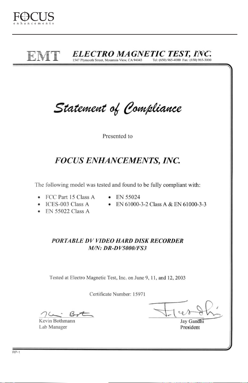
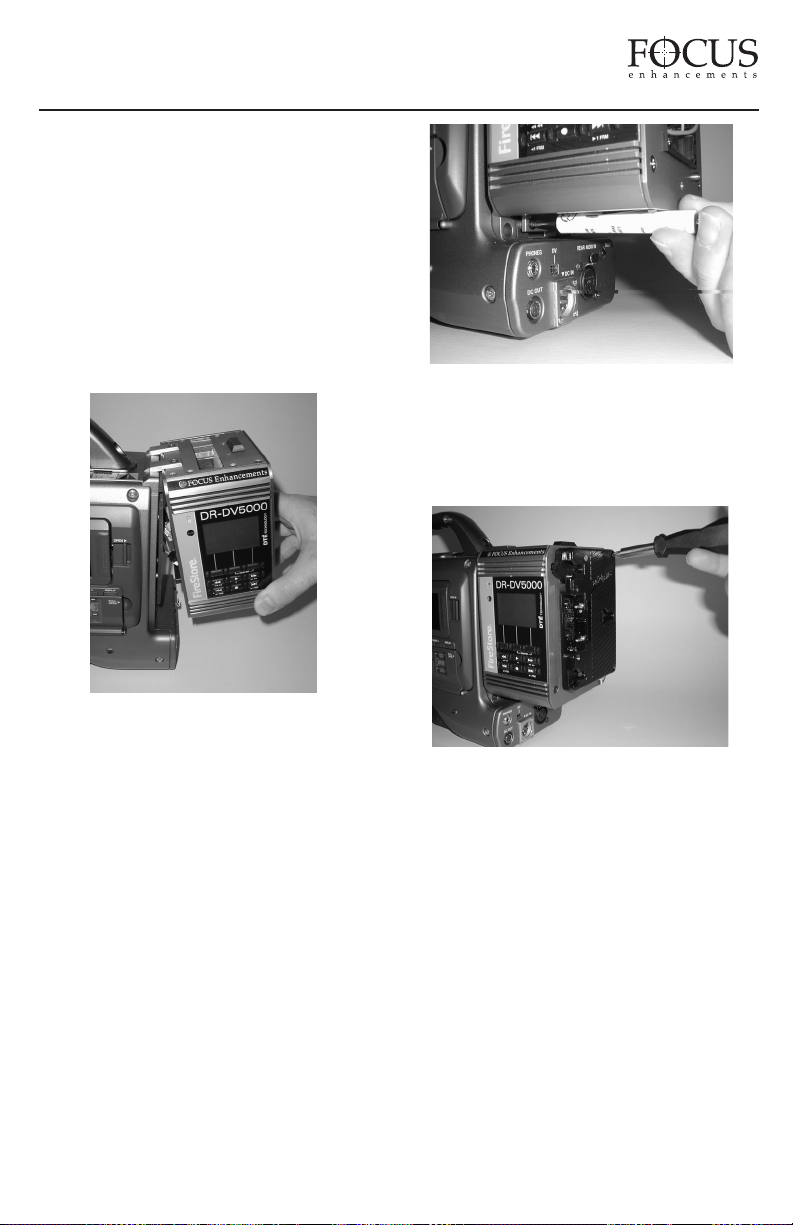
3) DR-DV5000 features a two wire connector
with black and red cables that connects main
power between the DR-DV5000 and the
camcorder. Connect this to the equivalent
connector on the rear of your camcorder.
FireStore DR-DV5000 User Guide
PAGE 9
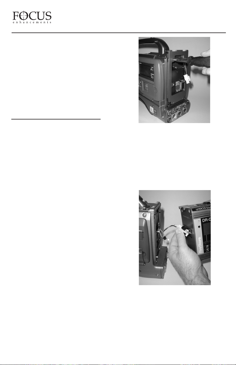
If you are using a digital battery system that
passes battery life status to the camcorder, and
are using a camcorder that is compatible with
these systems, connect the following cables
between DR-DV5000 and camcorder:
Anton/Bauer Digital Battery System
- Grey and Orange Cable
IDX Syncron Digital Battery System
- Blue and Red Cable
4) “Hook” the DR-DV5000 to the rear of the
the GY-DV5000 camcorder. If you are using
a JVC GY-DV5000 camcorder, use care to
ensure that the 52-pin connector on DRDV5000 mounts properly to the equivalent
connector on your camcorder. Harness any
loose cables into the “Hidey-Hole” on the DRDV5000.
5) Once mounted, secure the two captive
screws at the base of DR-DV5000 to the
camcorder. Ensure that no cables are
“pinched” between the DR-DV5000 and
the camcorder.
6) Re-attach the battery system to the rear
of the DR-DV5000. Ensure to connect all
power cables and utilize the supplied gasket
between DR-DV5000 and the battery system.
Harness any loose cables in the “Hidey-Hole”
on the rear of DR-DV5000.
FireStore DR-DV5000 User Guide
PAGE 10
PAGE 1
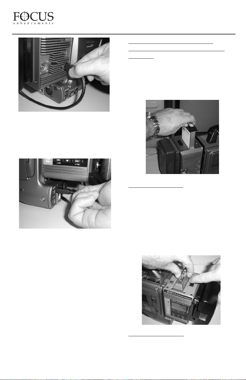
7) Finally, connect a 6-pin to 4-pin FireWire
cable from the 6-pin FireWire port on DRDV5000 marked “DV I/O” to the 4-pin
FireWire port on the rear of the camcorder
marked “DV”.
This final step is necessary on all JVC GYDV500, -550 and -700 series camcorders,
but may not be necessary on certain JVC
GY-DV5000 series camcorders. On certain
models, DV input/output is done via the 52pin connector between camcorder and DRDV5000. Check with JVC for information on
different models. A flexible wire clamp
located on the DR-DV5000 base provides
strain relief for the cable.
INSERTING AND REMOVING
FIRESTORE FSHDD-1 FIREWIRE
DRIVES
The best way to get to know the FireStore
FSHDD-1 FireWire HDD is by studying
the supplied manual. The manual provides
detailed instructions and illustrations.
INSER
TING THE HDD: Insert the drive into
the slot on top of the DR-DV5000 unit. Ensure
that the power switch on the bottom side of
the drive is set to “On” before inserting. The
drive will only insert one way and features a
“key” on one side to prevent incorrect
insertion. Press down on the drive handle
firmly until the handle meets the top of DRDV5000. If power is on, you will observe the
power LED light up green.
REMO
VING THE HDD: Slide the HDD
release latch on the DR-DV5000 top plate
toward the battery system. Once slid as far as
FireStore DR-DV5000 User Guide
PAGE 11

possible, hold the latch while at the same
time grasping the FSHDD-1 drive handle and
pulling the HDD out from DR-DV5000.
USING EXTERNAL FIREWIRE
DISK
DRIVES
In addition to using FireStore FSHDD-1
FireWire HDDs in the internal slot on DRDV5000, it is also possible to connect any
FireWire disk drive to the HDD I/O port on
DR-DV5000. Power a single FireWire disk
drive on DR-DV5000 at any given time (either
internal or external). If external drives are
being used as additional volumes to the
inserted FSHDD-1 FireWire HDD, it will be
necessary to provide external power to these
drives. It may also be necessary to partition
and format drives before use with DRDV5000. See page 32 of this user guide for
instructions on preparing drives before use.
NOTE: It is possible to "hot swap" both
internal and external FireWire HDDs on
DR-DV5000. Drives can be disconnected and
connected from the system without the need to
power cycle the unit. Ensure that DR-DV5000
is in STOP mode before removing a disk drive.
PHYSICAL FEATURES
Your FireStore DR-DV5000 features two
main surfaces, the front panel and the rear
connector panel.
FRONT PANEL
The front panel contains the backlit LCD
and nine buttons for controlling FireStore’s
functions. The top row of buttons act as Soft
Keys and provide the function displayed on
the bottom of the LCD.
The front panel also features a tally light,
infrared remote sensor and power switch.
1. Tally Light
The DR-DV5000 red tally light is located
at the top of the DR-DV5000 front panel. In
general, this light will flash when DR-DV5000
is in REC/PAUSE mode and be solid when in
RECORD mode. This light is also used to
warn the user when an error or warning
message appears on the DR-DV5000 LCD
display. See the “

PAGE 1
When used with a JVC GY-DV5000
series camcorder, DR-DV5000 communicates
with the camcorder first before power up or
shutdown. In cases where the camera power
is switched to off when DR-DV5000 is
connected and ON, the camcorder will wait
until DR-DV5000 is powered down first
before powering both down. Again, this
prevents errors occurring on particular files.
3. Infrared Remote Sensor
The DR-DV5000 infrared remote sensor
is for use with the DR-DV5000 infrared
remote commander. For information on the
DR-DV5000 infrared remote commander,
see “DR-DV5000 REMOTE CONTROL
COMMANDERS on page 39 of this User
Guide. This port can be disabled in infrared
noisy environments if desired in the DRDV5000 settings menu.
4. LCD Display Screen
The DR-DV5000 LCD screen displays status,
setup and warning/error messages relating to
DR-DV5000. The LCD backlight is set as
default to ON, but this can be set to OFF or
AUTO-OFF mode if desired. See page 30 of
this User Guide for details.
5. Keypad Soft Key Function
The bottom line of the DR-DV5000 LCD
screen displays Soft Key functions for the top
row of buttons. Soft Keys allow the function
of the top row of buttons to change depending
on particular modes.
6. Keypad Soft Key
The top row of buttons on the DR-DV5000
front panel are dedicated Soft Keys. Soft Key
functions change depending on what mode
DR-DV5000 is in. Current Soft Key function
is displayed on the bottom row of the LCD
screen. The left key on the top row of buttons
acts as a Soft Key and as the STOP key during
record sessions. The right key also acts as a
SHIFT key which allows Standard Keys to
have a secondary function.
7. Keypad Standard Keys
The bottom two rows of keys on the DRDV5000 keypad have dedicated functions such
as fast forward/back search, play, record, and
index forward back. Each key (except record)
also has a SHIFT mode which allows a
secondary function to be performed.
LCD DISPLAY
The DR-DV5000 LCD screen displays
different DR-DV5000 modes and states.
On boot up, DR-DV5000 will display the
following screen:
Depending on the connected disk drive,
DR-DV5000 may or may not display “Please
Wait” during boot up.
Once booted up, if no disk drive is connected
to the DR-DV5000 (either through the internal
slot or externally via the HDD I/O port), the
following screen will appear:
 Loading...