

Page 1

TView Pro AV 1600
USER’S MANUAL
Rev. 1.02
FOCUS Enhancements, Inc.
600 Research Drive
Wilmington, MA 01887
Phone: 978-988-5888
Fax: 978-988-7555
URL: www.FOCUSinfo.com
Page 2

1 INTRODUCTION...................................................................................................................................................................3
1.1 THE TV IEW PRO AV 1600 FAMILY..............................................................................................................................4
1.2 OPERATIONAL SPECIFICATIONS.................................................................................................................................6
2 INSTALLATION....................................................................................................................................................................9
2.1 PC DESKTOP V ERSION................................................................................................................................................. 10
2.2 MAC DESKTOP V ERSION............................................................................................................................................ 11
2.3 SUN OR SGI DESKTOP V ERSION................................................................................................................................. 12
2.4 WORKSTATION DESKTOP V ERSION..........................................................................................................................13
3 TVIEW PRO AV 1600 CONTROLS AND ADJUSTMENTS ......................................................................................14
3.1 TV IEW PRO AV 1600 INTERFACE CONTROLLABLE FUNCTIONS.........................................................................14
3.2 INTERNAL ADJUSTMENTS..........................................................................................................................................19
4 TVIEW PRO AV 1600 CONTROL METHODS.............................................................................................................21
4.1 FRONT PANEL CONTROL ............................................................................................................................................ 21
4.2 REMOTE CONTROL ...................................................................................................................................................... 22
4.3 RS-232/422 CONTROL..................................................................................................................................................22
5 HYPERFORMANCE UTILITY SOFTWARE ...................................................................................................................29
5.1 HYPERFORMANCE COMPONENTS.............................................................................................................................29
APPENDIX A - LIMITED WARRANTY ....................................................................................................................................32
APPENDIX B - HYPERFORMANCE UTILITY SOFTWARE LICENSE .............................................................................33
APPENDIX C – GENLOCK.........................................................................................................................................................34
APPENDIX D - COMPONENT OUTPUT..................................................................................................................................35
TView Pro AV 1600 User's Manual Rev 1.02
2
Page 3

1 Introduction
The FOCUS Enhancements TView Pro AV 1600 product family is a series of products that produce standard,
recordable NTSC or PAL base band video from High-Resolution Computer Graphics devices.
The TView Pro AV 1600 automatically senses the input resolution and frequency of the incoming Computer Graphics
signal and transforms the resolution of input Computer Graphics to full screen, 24 bit color, NTSC or PAL Video. The
TView Pro AV 1600 performs this transformation without disturbing the input Computer Graphics signal in any way;
High-Resolution Computer Graphics appears on the System's Computer Graphics Monitor (using a buffered loopthrough) exactly as if the TView Pro AV 1600 was not there.
The TView Pro AV 1600’s output is fully broadcast compatible, with the ability to Genlock to a reference video or
black burst signal. Independent adjustments allow full control over H phase and subcarrier phase.
TView Pro AV 1600 User's Manual Rev 1.02
3
Page 4

1.1 The TView Pro AV 1600 Family
The TView Pro AV Product Family consists of one common technology implemented on a common circuit board.
Depending on the specific model, different ICs and accessories are added to the base product to provide specific
options.
1.1.1 Board or Desktop or Rackmount
TView Pro AV 1600 units are configured as Board Units (PCI boards) or Desktop Units or Rackmount Units. The
Board Units mount inside the PC and receive their electrical power from the computer.
Desktop Units are stand alone items that accept 13.5 VDC power from a UL listed power supply. Users of Desktop
TView Pro AV 1600s may choose between American compatible, wall mount transformers, with standard American
plug configuration (shipped automatically with Pro AV Desktop, NTSC orders) or deskmount universal power
supplies (shipped with Pro AV Desktop orders). Desktop universal power supplies terminate in an IEC-320 connector
(the same connector that you see on the back of PC computers). You must supply the wall outlet to IEC-320 cable.
TView Pro AV1600 is also available in an EIA 19 inch rack mount configuration. The TView Pro AV 1600-R occupies
1 standard rack height. All TView Pro AV 1600-R models are capable of accepting power in the range of 95 V - 250 V,
47Hz. to 63 Hz. FOCUS Enhancements does not supply the IEC-320 to wall outlet cable.
1.1.2 IBM or Mac or Workstation
The TView Pro AV 1600 is compatible with IBM PC (ISA) computers, MAC computers and many popular
workstations. The same Desktop unit may be used with any personal computer or workstation, however the
appropriate cable kits must be ordered. The Pro AV 1600 is shipped with a PC cable and a Mac Adapter Kit. Any
cable or cable kit may be ordered separately at a later date.
In the IBM family, the Pro AV 1600 supports VGA and super VGA devices in all VGA standard modes (640 x 480,
EGA, Text and 320 x 200 modes, all 800 x 600 modes from 56 - 76 Hz Vertical Non-Interlaced, all 1024 x 768 modes from
60 - 76 Hz and all 1280 x 1024 modes from 60 - 76 Hz Vertical Non-Interlaced. The 1024 x 768 Non-Interlaced modes of
the XGA-2 are also supported.
In the Macintosh family, The Pro AV 1600 supports 640 x 480, 66.7 Vertical Non-Interlaced mode (Applecolor
High-Resolution RGB Monitor, often referred to as the 13" display) and the 1024 x 768, 66.7 Hz Vertical
Non-Interlaced mode (AppleVideo RGB Monitor, often referred to as the 21" display).
In addition to IBM PC and Macintosh video formats, the TView Pro AV 1600 also accepts computer video in popular
workstation formats as well (up to its 1024 x 768 limit). The TView Pro AV 1600 is capable of decoding a separate
composite synchronization signal, as well as a composite sync signal embedded in the green signal. The correct
cable kit is required for successful use with a workstation.
TView Pro AV 1600 User's Manual Rev 1.02
4
Page 5

1.1.3 Standard Packout for TView ProAV 1600 (Desktop) (SKU #444-6210)
1 TView ProAV 1600 desktop unit
1 American Wall Transformer
1 BNC Male – BNC Male cable
1 BNC Female – RCA Male adapter
1 S-VHS Male to S-VHS Male cable
1 HD-15 Male – HD –15 Female cable
1 TView Pro AV Remote Control
2 AAA Batteries
1 Tview Pro AV Manual
1.1.4 Standard Packout for TView ProAV International (Desktop) (SKU #444-6212)
1 TView ProAV 1600 desktop unit
1 IEC-320 International Power Supply
1 BNC Male – BNC Male cable
1 BNC Female – RCA Male adapter
1 S-VHS Male to S-VHS Male cable
1 HD-15 Male – HD –15 Female cable
1 TView Pro AV Remote Control
2 AAA Batteries
1 Tview Pro AV Manual
1.1.5 Standard Packout for TView ProAV (Rackmount) (SKU #444-6230)
1 TView ProAV rackmount unit
1 BNC Male – BNC Male cable
1 BNC Female – RCA Male adapter
1 S-VHS Male to S-VHS Male cable
1 HD-15 Male – HD –15 Female cable
1 TView Pro AV Remote Control
2 AAA Batteries
1 Tview Pro AV Manual
1.1.6 Accessory Items
The following items may be ordered separately as accessories:
444-5906 HD15 Male – 5 BNC Male Cable (PC)
444-5907 HD15 Female – 5 BNC Male Cable (PC)
444-5908 DB-15 Male – 5 BNC Male Cable (Mac)
444-5909 DB-15 Female – 5 BNC Male Cable (Mac)
444-5910 13W3 Male – 5 BNC Male Cable(Sun)
444-5914 5 BNC-Male – 5 BNC Male Extender Cable
3201-0901 RS-232 Control Cable
TView Pro AV 1600 User's Manual Rev 1.02
5
Page 6

1.2 Operational Specifications
1.2.1 Input Resolutions
All original IBM VGA Modes
640 x 480 72 Hz. (S-VGA Vesa Spec. VS900101)
640 x 480 75 Hz. (S-VGA Vesa Spec. VGMT)
800 x 600 56 Hz. (S-VGA Vesa Spec. VG900601)
800 x 600 60 Hz. (S-VGA Vesa Spec. VG900602)
800 x 600 72 Hz. (S-VGA Vesa Spec. VS900603)
800 x 600 75 Hz. (S-VGA Vesa Spec. VGMT)
1024 x 768 60 Hz. (S-VGA Vesa Spec. VG901101)
1024 x 768 70 Hz. (S-VGA Vesa Spec. VS910801)
1024 x 768 75 Hz. (S-VGA Vesa Spec. VGMT)
1024 x 768 60-76 Hz. (IBM XGA-2 Non-Interlaced modes)
(requires 9515 or 9517 monitor)
1280 x 1024 60 Hz (SXGA Vesa Spec. VDMTREV)
1280 x 1024 75 Hz (SXGA Vesa Spec. VDMT75HZ)
1280 x 1024 85 Hz (SXGA Vesa Spec. VDMTPROP)
1600 x 1200 60-85Hz (UXGA Vesa Spec. VDMTREV)
640 x 480 66.7 Hz. (AppleColor High-Resolution 13" RGB Monitor)
1024 x 768 60 Hz. (AppleVideo 21" RGB Monitor)
Or any computer video resolution up to 1600x1200 at up to 120Hz.
All workstation modes in the range of 640 x 480 to 1600 x 1200
THE TVIEW PRO AV 1600 DOES NOT SUPPORT INTERLACED INPUT.
1.2.2 Input Color Capability
All input formats are internally converted, and processed as 24 bit RGB signals. The TView Pro AV 1600 is therefore
capable of handling an input color space of up to 16.8 million colors.
1.2.3 Output Resolutions
NTSC
484 displayed lines vertically
Underscan/Overscan Switch selectable
PAL
576 displayed lines vertically
Underscan/Overscan Switch selectable
TView Pro AV 1600 User's Manual Rev 1.02
6
Page 7

1.2.4 Digital Flicker Reduction Filter
A multistage Digital Flicker Reduction Filter is a standard feature of all models of the TView Pro AV 1600. The Flicker
Filter may be engaged at one of seven different levels or disengaged by any one of the control methods.
TView Pro AV 1600 User's Manual Rev 1.02
7
Page 8

1.2.5 TView Pro AV 1600 Connectors (Desktop Model)
(with reference to TView Pro AV 1600)
Computer Video Input HD15 Male
Computer Video Output HD15 Female
Composite Video Output Female BNC
(Female RCA optionally available)
S-Video Mini-Din 4 position female
Genlock Female BNC
Component Female BNC
RS-232/422 Female DB9
Power 2.5 mm Barrel Connector male
1.2.6 Power Consumption
Desktop Unit:
120 V. 0.25 A.
240 V. 0.15 A.
1.2.7 Physical Size
Desktop Unit:
7.5" X 7.25" X 2.0”"
1.2.8 Environmental
Temperature:
Operating: 0 – 40 degrees Celsius
Non-Operating: -40 to 70 degrees Celsius
Humidity:
Operating: 15% to 80% non-condensing
Non-Operating: 10% to 95% non-condensing
Altitude:
Operating: -500 to 15000 ft. ASL
Non-Operating: -1000 to 50000 ft. ASL
Electromagnetic:
Susceptibility: EN50082-1
Radiation: CISPR 22 (1993-12), FCC Class B
TView Pro AV 1600 User's Manual Rev 1.02
8
Page 9
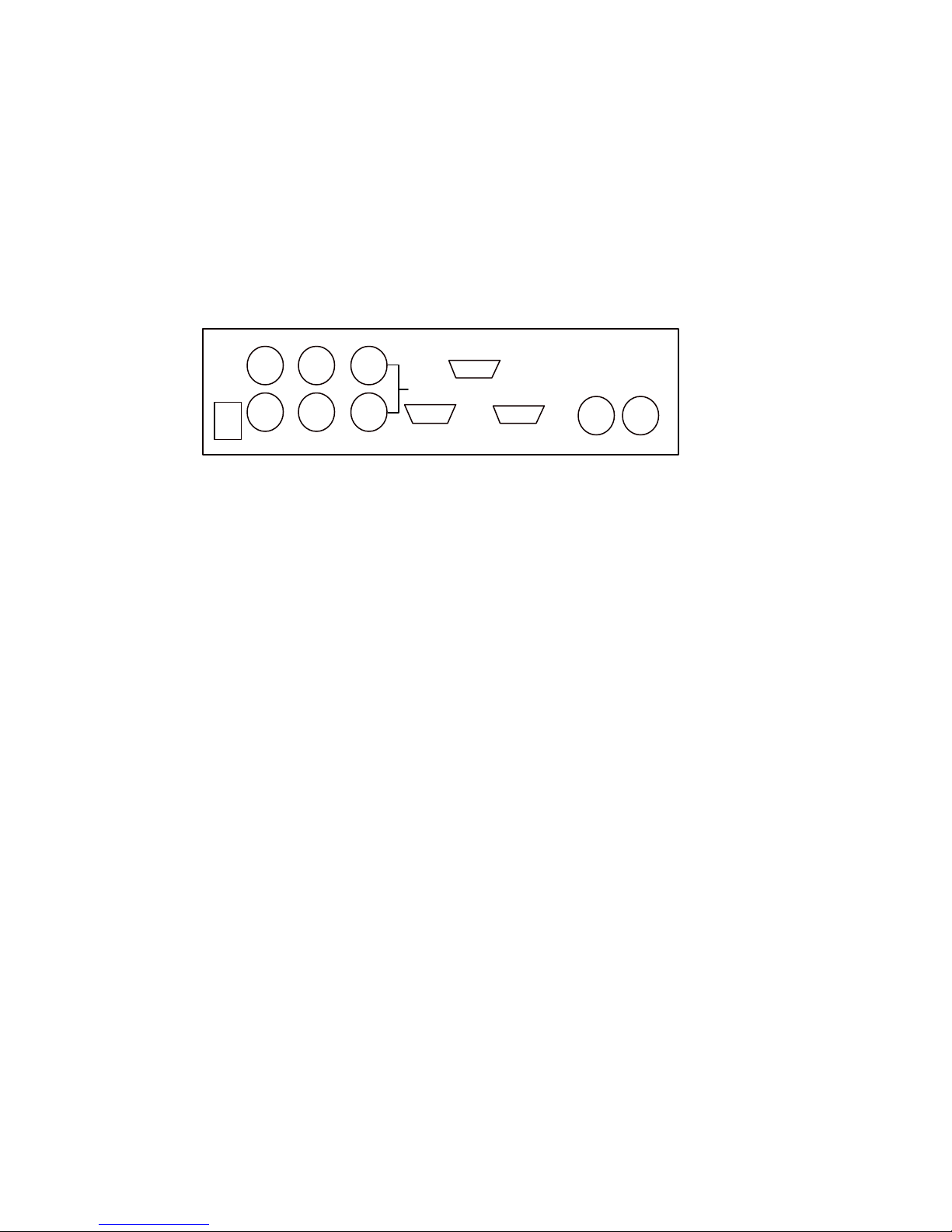
2 Installation
Installation of all TView Pro AV 1600 products is a simple and quick procedure, but is slightly different for each of the
following versions.
12-18 VDC
23 W.
2.5 MM
Red/R-Y Out
Blue/B-Y
Out
Sync Out
Green/Y
Out
RS-232/422
GenLock Thru
VGA In VGA Out
Figure 1: TView Pro AV Desktop Back Plate Diagram
S-Video
Out
NTSC/PAL
Out
TView Pro AV 1600 User's Manual Rev 1.02
9
Page 10

2.1 PC Desktop Version
All TView Pro AV 1600 Desktop Units will work with IBM PC family computers. Units are shipped with a PC cable,
and Macintosh Adapter. Workstation cables can be ordered.
Follow these steps to install your Desktop TView Pro AV 1600 for PC or MAC systems. If you intend to use the
TView Pro AV 1600 with Genlock or component output please see Appendix C (Genlock operation) and Appendix D
(Component output) for further information on these features.
1. Turn the computer off.
2. Select a convenient location for the TView Pro AV 1600.
3. Disconnect the Computer Display from the Graphics Card on the Computer .
4. Connect one end of the PC video cable into the graphics card on the computer (The location from which the
computer display was removed). Connect the other end of the cable into the VGA In connector of the TView Pro
AV 1600.)
5. Connect the Computer Display to the VGA Out Connector of the TView Pro AV 1600.
6. Connect your Video Device to the Composite Video and/or S-Video output connector. (You may connect both
outputs simultaneously to the same or different Video Devices: Video is always available on both these outputs.)
7. Plug the 13.5 VDC Power Supply's jack into the TView Pro AV 1600’s power input (marked 12-18 VDC, 23W, 2.5
mm).
8. Plug the 13.5 VDC Power Supply into an electrical outlet. (If you have a Universal Power Supply, you will have
to supply an appropriate IEC-320 compatible power cord for your country).
9. Turn the TView Pro AV 1600 On.
10. From the Front Panel or RS-232/422 control, set the Sync Selection to “IN= VGA SYNC”. (See section 3.1.19 for
additional details on Sync Selection.)
11. Turn the System On. If everything is correctly installed, you will see your computer's normal power up sequence
appearing on both the Computer Display and the Video Device (if the Video Device has a visible display).
TView Pro AV 1600 User's Manual Rev 1.02
10
Page 11

2.2 MAC Desktop Version
Follow these steps to install your Desktop TView Pro AV 1600 for Macintosh systems. If you intend to use the
TView Pro AV 1600 with Genlock or component output please see Appendix C (Genlock operation) and Appendix D
(Component output) for further information on these features.
1. Turn the computer off.
2. Select a convenient location for the TView Pro AV 1600.
3. Disconnect the Computer Display from the Computer Graphics device at the Computer Graphics device.
4. Using the Macintosh Adapters connect one end of the PC video cable into the graphics card on the computer
(The location from which the computer display was removed). Connect the other end of the cable into the VGA
In connector of the TView Pro AV 1600.
5. Using the Macintosh Adapter connect the computer display to the video out connector on the TView Pro AV
1600.
6. Connect your Video Device to the Composite Video and/or S-Video output connector. (You may connect both
outputs simultaneously to the same or different Video Devices: Video is always available on both these outputs.)
7. Plug the 13.5 VDC Power Supply's jack into the TView Pro AV 1600’s power input (marked 12-18 VDC, 23W, 2.5
mm).
8. Plug the 13.5 VDC Power Supply into an electrical outlet. (If you have a Universal Power Supply, you will have
to supply an appropriate IEC-320 compatible power cord for your country).
9. Turn the TView Pro AV 1600On.
10. From the Front Panel or RS-232/422 control, set the Sync Selection to “IN= MAC SYNC”. (See section 3.1.19 for
additional details on Sync Selection.)
11. Turn the System On. If everything is correctly installed, you will see your computer's normal power up sequence
appearing on both the Computer Display and the Video Device (if the Video Device has a visible display).
TView Pro AV 1600 User's Manual Rev 1.02
11
Page 12

2.3 Sun or SGI Desktop Version
Follow these steps to install your Desktop TView Pro AV 1600 for SGI or Sun systems. If you intend to use the
TView Pro AV with Genlock or component output please see Appendix C (Genlock operation) and Appendix D
(Component output) for further information on these specialty items.
1. Turn the computer off.
2. Select a convenient location for the TView Pro AV 1600.
3. Disconnect the Computer Display from the Computer Graphics device at the Computer Graphics device.
4. Connect the HyperCableGOLD-13W,13W3M-HD15F cable into the Computer Graphics Device. Connect the
other end of the HyperCableGOLD-13W ,13W3M-HD15Fcable into the VGA In connector of the TView Pro AV
1600.
5. Connect the HyperCableGOLD-13W ,HF15M-13W3F cable into the VGA Out connector of the TView Pro AV
1600.
6. Connect the Computer Display to the female end of the HyperCableGOLD-13W,HF15M-13W3F cable.
7. Connect your Video Device to the Composite Video or S-Video output connector. (You may connect both
outputs simultaneously to the same or different Video Devices: Video is always available on both these outputs.)
8. Plug the 13.5 VDC Power Supply's jack into the TView Pro AV 1600’s power input (marked 12-18 VDC, 23W, 2.5
mm).
9. Plug the 13.5 VDC Power Supply into an electrical outlet. (If you have a Universal Power Supply, you will have
to supply an appropriate IEC-320 compatible power cord for your country).
10. Turn the TView Pro AV 1600 On.
11. From the Front Panel or RS-232/422 control, set the Sync Selection to “IN= MAC SYNC” or “IN= GRN SYNC”,
depending on whether your workstation delivers separate composite sync (also referred to as 4 wire) or
composite sync on green (also referred to as 3 wire). As a general rule, Sun systems are 4 wire, SGI systems are
3 wire and all other workstation (DEC, HP, IBM, etc. are 3 wire). See section 3.1.19 for additional details on
Sync Selection.
12. Turn the System On. If everything is correctly installed, you will see your computer's normal power up sequence
appearing on both the Computer Display and the Video Device (if the Video Device has a visible display).
TView Pro AV 1600 User's Manual Rev 1.02
12
Page 13

2.4 Workstation Desktop Version
Follow these steps to install your Desktop TView Pro AV 1600 for Workstations that use BNC connectors for output
video. If you intend to use the TView Pro AV 1600 with Genlock or component output please see Appendix C
(Genlock operation) and Appendix D (Component output) for further information on these specialty items.
1. Turn the computer off.
2. Select a convenient location for the TView Pro AV 1600.
3. Disconnect the Computer Display from the Computer Graphics device at the Computer Graphics device.
4. Connect the BNC connectors of the Cable, HD15 M to 5 BNC M cable into the Computer Graphics Device.
Connect the other end of the Cable, HD15 M to 5 BNC M cable into the HD15 F to F, Genderchanger. Finally
connect the other end of the HD15 F to F, Genderchanger into the VGA In connector of the TView Pro AV.
5. Connect another Cable, HD15 M to 5 BNC M cable into the VGA Out connector of the TView Pro AV 1600.
Finally connect the BNC Connectors of the Cable, HD15 M to 5 BNC M into the Display Device.
6. Connect your Video Device to the Composite Video or S-Video output connector. (You may connect both
outputs simultaneously to the same or different Video Devices: Video is always available on both these outputs.)
7. Plug the 13.5 VDC Power Supply's jack into the TView Pro AV 1600’s power input (marked 12-18 VDC, 23W, 2.5
mm).
8. Plug the 13.5 VDC Power Supply into an electrical outlet. (If you have a Universal Power Supply, you will have
to supply an appropriate IEC-320 compatible power cord for your country).
9. Turn the TView Pro AV 1600 On.
10. From the Front Panel or RS-232/422 control, set the Sync Selection to “IN= MAC SYNC” or “IN= GRN SYNC”,
depending on whether your workstation delivers separate composite sync (also referred to as 4 wire) or
composite sync on green (also referred to as 3 wire). As a general rule, Sun systems are 4 wire, SGI systems are
3 wire and all other workstation (DEC, HP, IBM, etc. are 3 wire). See section 3.1.19 for additional details on Sync
Selection.
11. Turn the System On. If everything is correctly installed, you will see your computer's normal power up sequence
appearing on both the Computer Display and the Video Device (if the Video Device has a visible display).
TView Pro AV 1600 User's Manual Rev 1.02
13
Page 14

3 TView Pro AV 1600 controls and adjustments
There are several parameters on the TView Pro AV 1600 that can be controlled through by the TView Pro AV 1600's
control interfaces. TView Pro AV models have three methods of control: front panel control, RS-232/422 and IR
remote control. All methods are interchangeable and simultaneously active (i. e. a front panel button push can be
followed by an IR remote control command).
Not all controllable items are accessible by the IR remote mouse. This provision is deliberately intended to prevent
the user of an IR remote mouse from accidentally changing the video standard from NTSC to PAL, etc., at a critical
moment in a presentation.
Additional adjustments to functions that are likely to accessed infrequently - or are intended to be adjusted by
service personnel only - are available in the form of potentiometers, variable capacitors and jumpers on the TView Pro
AV 1600 board itself. Access to these internal adjustments requires the removal of the TView Pro AV 1600's cover.
3.1 TView Pro AV 1600 Interface Controllable Functions
The following parameters are accessible using the TView Pro AV 1600's control interfaces. Each of the controls has
one of three possible types of parameters associated with it, Toggle (the function is either on or off), Multiple Choice
(there are several, mutually exclusive options) or Range (the parameter varies over a range of values for a particular
function). Section 4 details the use of each of the Control interfaces.
3.1.1 Horizontal/Vertical Position (Range)
This control enables the user to position the converted Computer Graphics with respect to the output television. The
actual functioning of this control is dependent on the state of the Zoom function. If Zoom is off, H/V Position
enables minor changes in position of the full screen image. If Zoom is on, H/V position functions as a pan and scroll
control, positioning the input window for zooming.
3.1.2 Horizontal/Vertical Size (Range)
This control enables the user to size the converted Computer Graphics with respect to the output television. The
actual functioning of this control is dependent on the state of the Zoom function. If Zoom is off, H/V Size enables
minor changes in size of the full screen image. If Zoom is on, the H/V Size Control is inactive. To properly size the
PC output to the television screen follow these steps
1. Position the underscanned image to the top, left corner of the television screen
2. Toggle the Pro AV control panel to H,V Sizing
3. Use the IR remote control pad or arrow keys to size the screen both horizontally and vertically
3.1.3 Zoom (Toggle)
This control applies a 2X Zoom to a portion of the input Computer Graphics. The position of the window is
determined by the H/V Position control.
3.1.4 UnderScan (Toggle)
This control selects whether Underscan is applied to the Television Output. An "UnderScanned" picture slightly
shrinks the whole display such that information in the corners is visible. Select “UNDERSCAN” when you have text
or detail oriented pictures that requires you to preserve fine detail in the corner regions of the display. An
"OverScanned" picture fills the entire area of the screen, which is the natural way of presenting material in television.
Select “OVERSCAN” to present photo-realistic and animation oriented material.
TView Pro AV 1600 User's Manual Rev 1.02
14
Page 15

3.1.5 Terminate VGA (Toggle)
This control connects the TView Pro AV1600's 75 Ohm termination resistors onto the computer's RGB output lines.
Select “TERMINATED” unless you are using the TView Pro AV 1600 with a pass through monitor cable (such as a
HyperCable-PC, intended for use with the Pro AV CP product line).
3.1.6 Fine Genlock H Position (Range) (Not available from IR remote mouse)
This control adjusts the relative horizontal picture position of the Television Output with respect to a Reference
Television signal. This control is only operational when using the Genlock capability of the TView Pro AV 1600.
3.1.7 Coarse Genlock H Position (Range) (Not available from IR remote mouse)
This control adjusts the relative horizontal picture position of the Television Output with respect to a Reference
Television signal. This control is only operational when using the Genlock capability of the TView Pro AV 1600.
3.1.8 Genlock Subcarrier Phase (Range) (Not available from IR remote mouse)
This control adjusts the relative Subcarrier Phase of the Television Output with respect to a Reference Television
signal. This control provides slightly more than 180 degrees of variable phase control and most be used in
conjunction with the Genlock Subcarrier Phase Reverse Control to establish 360 degrees of phase control. This
control is only operational when using the Genlock capability of the TView Pro AV 1600.
3.1.9 Genlock Subcarrier Phase Reverse (Toggle) (Not available from IR remote
mouse)
This control selects 180 degrees of Television Output Subcarrier Phase shift with respect to a Reference Television
signal. This control is only operational when using the Genlock capability of the TView Pro AV 1600.
3.1.10 Genlock Termination (Toggle) (Not available from IR remote mouse)
This control applies a 75 Ohm termination to the Genlock input. This control is always operational.
3.1.11 NTSC/PAL (Toggle) (Not available from IR remote mouse)
This control selects between PAL and NTSC operation. Set this control to PAL for European operation. Set this
control to NTSC for American operation.
3.1.12 Flicker Reduction Filter (Multiple)
This control operates the Flicker Reduction Filter. Flicker filter settings from 0 (Flicker Filter is Off) to 7 (Flicker Filter
is at a maximum) are available. The display will indicate “FLK FLT = #” where # is the current setting of the Flicker
Filter.
3.1.13 Brightness Boost (Toggle) (Not available from IR remote mouse)
This control applies a Brightness Boost to the Television Output. Set “BRIGHT MAX” to raise the brightness of the
Television Output. Set “BRIGHT NORM” to set the Television Output to regulation brightness level.
3.1.14 Freeze Frame (Toggle)
This control freezes the output video of the TView Pro AV. Select “INPUT FROZEN” to freeze the picture. Select
“INPUT LIVE” to view live input.
TView Pro AV 1600 User's Manual Rev 1.02
15
Page 16

3.1.15 IR Remote Disable (Toggle) (Not Available from IR remote mouse)
This control disables the operation of the IR remote mouse. Select “IR ON” to enable the operation of the remote
mouse. Select “IR OFF” to disable the operation of the IR Remote Mouse and prevent IR conflicts.
3.1.16 Colorbar Pattern Enable (Toggle) (Not available from the IR Remote Mouse)
This control enables the Colorbar pattern to be displayed at the television output. Use the Colorbar test pattern to
test for succesful connection of the Pro AV 1600 to the television device; no input source is required. Select
“COLORBAR ON” to enable the color bar pattern to be displayed at the output. Select “COLORBAR OFF” for
normal operation.
3.1.17 YUV /RGB Selection mechanism (Toggle) (Not available from IR remote mouse)
This control selects the color space of the component output. Select “RGB OUTPUT” for RGB appearing on the R-Y,
Y and B-Y connectors respectively. Select “YUV OUTPUT” for BetaCam levels of R-Y, Y and B-Y appearing on the
R-Y, Y and B-Y connectors respectively.
3.1.18 Sync Selection (Multiple) (Not available from IR remote mouse)
This control determines how the TView Pro AV will interpret input synchronization signals from the Computer
Graphics device. Select “IN= VGA SYNC” for VGA input and other devices that provide 5 wire video signals (i. e.
Red, Green, Blue, and H and V sync). Select “IN= MAC SYNC” for Macintosh input and other devices that provide
4 wire video signals (i. e. Red, Green, Blue, and a composite sync). Select “IN= GRN SYNC” for Workstation input
and other devices that provide 3 wire video signals (i. e. Red, Green, Blue, with composite sync on Green).
3.1.19 Contrast (Range) (Not available from IR remote mouse)
This control enables the user to control the contrast of the output video. The relative value of contrast is indicated
on a scale of 0 to 127. The default value is 62.
3.1.20 Brightness (Range) (Not available from IR remote mouse)
This control enables the user to control the brightness of the output video. The relative value of brightness is
indicated on a scale of 0 to 127. The default value is 60.
3.1.21 Saturation (Range) (Not available from IR remote mouse)
This control enables the user to control the saturation of the output video. The relative value of contrast is indicated
on a scale of 0 to 127. The default value is 127.
3.1.22 Save Configuration (Multiple) (Not available from IR remote mouse)
The Pro AV 1600 enables the storage of 15 user defined parameter sets of all of its control settings. (A 16th
SaveRecall parameter set is automatically saved and recalled on power-up.) To save the current setting select the
Save command with the + / - buttons. The next configuration to be saved will be indicated on the display. The act of
pressing any one of the arrow buttons will cause the current set of parameters to be saved as “Save Set #” (where #
is the # appearing on the display). The display will immediately increment to the next Save Set number. The Save
feature is not available from RS-232/422 Control.
TView Pro AV 1600 User's Manual Rev 1.02
16
Page 17

3.1.23 Recall Configuration (Multiple) (Not available from IR remote mouse)
Using the Recall Configuration feature, the user can instantly recall any previously saved Save Set. The up or down
arrow keys select from previously configured Save Sets. Recall Configuration is not available from RS-232/422
Control.
3.1.24 Erase Configuration (Multiple) (Not available from IR remote mouse)
The Erase Configuration feature is the inverse of the Save Configuration. To erase the most recently saved
configuration enter the Erase command with the + / - buttons. The last configuration to be saved will be indicated on
the display. The act of pressing any one of the arrow buttons will cause the numbered set of parameters “Save Set
#” (where # is the # appearing on the display) to be erased. The display will immediately decrement to the next Save
Set number. The Erase feature is not available from RS-232/422 Control.
TView Pro AV 1600 User's Manual Rev 1.02
17
Page 18

3.1.25 Auto Reset
This control resets the TView Pro AV to its default settings. Default Settings are as follows:
Function Auto Reset Parameter Valu e
Horizontal/Vertical Position Best Factory Estimate
Horizontal/Vertical Size Best Factory Estimate
Zoom Off
UnderScan Overscanned
Terminate TERMINATED
Fine Genlock H Position Best Factory Estimate
Coarse Genlock H Position Best Factory E stimate
Genlock Subcarrier Phase Best Factory Estimate
Genlock Subcarrier Phase Reverse 0 degrees
Genlock Termination Genlock input Unterminated
NTSC/PAL as originally shipped
Sharpness FLICKER OFF
Brightness Boost Off
Freeze Frame INPUT L IVE
IR Remote Enabled
Colorbar Test Pattern Disabled
YUV/RGB Selection RGB OUTPUT
Sync Selection IN = VGA SYNC
Recall Configurations All are preserved
TView Pro AV 1600 User's Manual Rev 1.02
18
Page 19

3.2 Internal Adjustments
The following adjustments are internal adjustments. These controls require the user to remove the TView Pro AV
1600’s cover and make the indicated adjustment with an adjustment tool.
3.2.1 Color Burst Level VR1
This potentiometer adjusts the amplitude of the Color Burst.
3.2.2 Output NTSC Pedestal VR2
This potentiometer adjusts the level of the NTSC Pedestal.
3.2.3 RGB Output Level VR9
This potentiometer adjusts the RGB Output Level
3.2.4 FSC-403 Reference Voltage VR10
This potentiometer adjusts the Voltage Reference on the FSC-403 chip.
3.2.5 Sync on Y output Insertion JP6
This jumper determines whether composite sync is inserted on the Y output. Connect the 2 posts of this jumper
together to produce sync on the Y output. Sync is always available on the dedicated component sync output
connector. The factory default is Sync on Y selected (Jumper JP6 installed).
3.2.6 Pal GenLock Trim Cap C6
Adjusts PAL color frequency
3.2.7 NTSC Genlock Trim Cap C11
Adjusts NTSC color frequency
TView Pro AV 1600 User's Manual Rev 1.02
19
Page 20
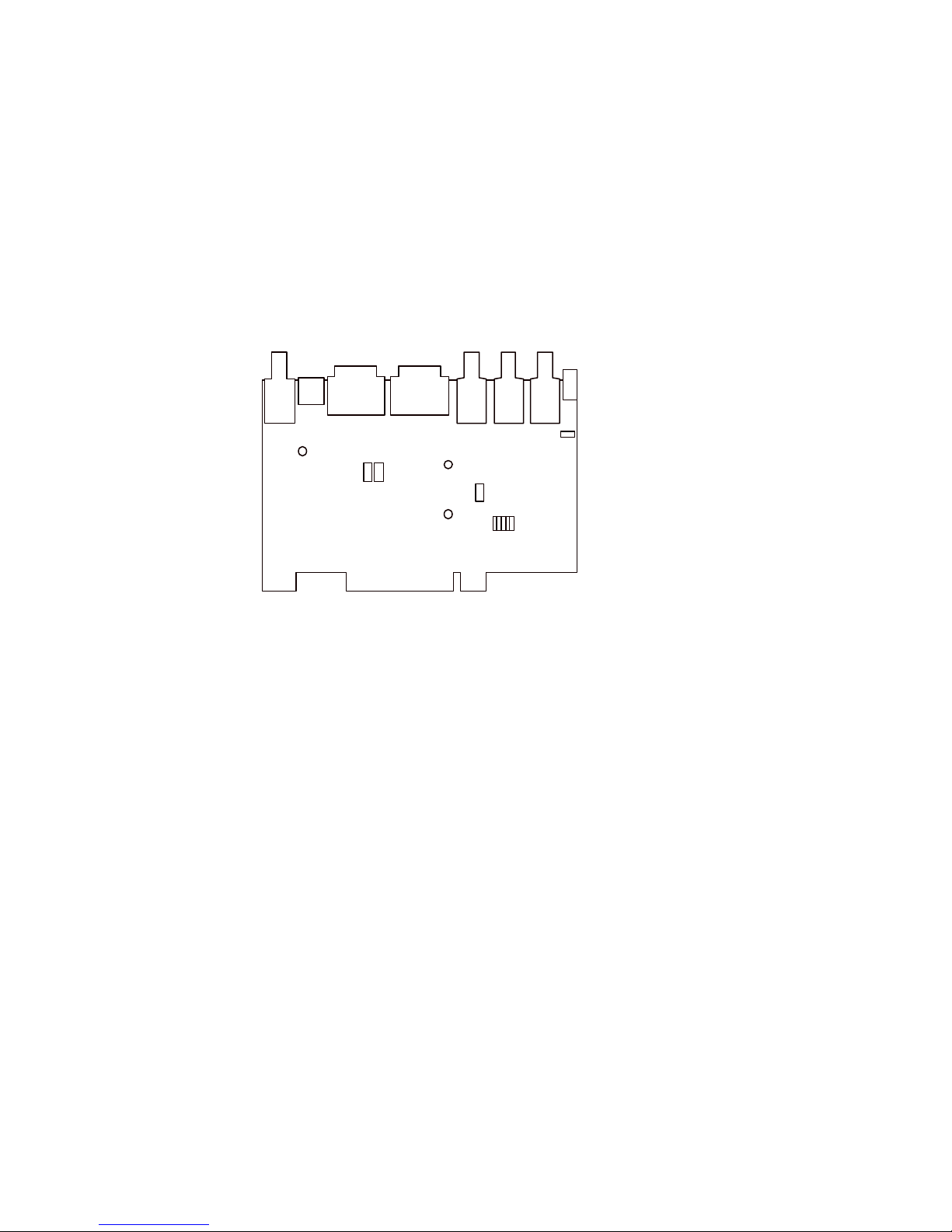
Figure 2: Adjustments and Jumpers
VR2
VR9
VR1
C11
JP10
JP6C6V10
TView Pro AV 1600 User's Manual Rev 1.02
20
Page 21
4 TView Pro AV 1600 Control Methods
+
TView Pro AV 1600 models can be controlled in one of 3 different ways: Front Panel, RS-232/422, or InfraRed Remote
Control. The following sections detail the use of each of these control mechanisms. In all cases, the state of a
particular function of the Pro AV 1600 is indicated on the TView Pro AV 1600's Front Panel LED readout.
4.1 Front Panel Control
The TView Pro AV 1600 Front Panel gives the user access to all of the control parameters detailed in section 3.1.
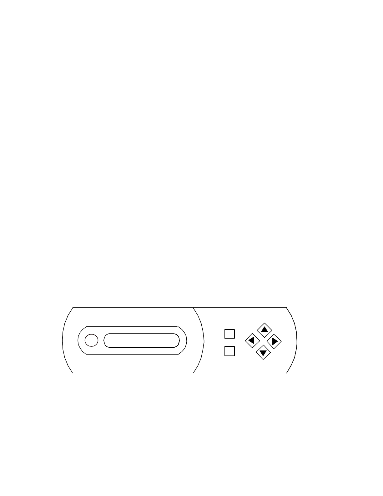
Figure 3 indicates the placement of the buttons and LED display on the Front Panel of the TView Pro AV..
The controls are arranged such that the user can cycle through a circular list of controllable functions with the + or buttons. Using the + button advances the controlled item to the next item in the list. Using the - button reverses the
controlled item to the previous item in the list. Depending on the nature of the controlled item, the directional arrow
buttons function differently.
If the controlled item is a Toggle (i. e. Underscan, Sharpness, NTSC/PAL, etc.) with a position of either On or Off,
then the activation of any one of the arrow buttons will toggle the state of the controlled item.
If the controlled item is a Multiple Choice (i. e. Sync Selection) with several mutually exclusive positions, then the
activation of any one of the arrow buttons will change the state of the controlled item to the next state. When the
last state is reached, the next state will be the first state.
If the controlled item is a Range (i. e. Horizontal/Vertical Size, Horizontal/Vertical Position, Genlock H Position, etc),
then the arrow buttons increase or decrease the value of these quantities. The increase or decrease is proportional to
the length of time that the button is pressed.
Figure 3: Position of Front Panel Controls
TView Pro AV 1600 User's Manual Rev 1.02
-
21
Page 22

4.2 Remote Control
The hand held IR remote control enables the user to access many of the functions of the TView Pro AV 1600. Since
the IR unit is intended to be used in presentation situations, certain functions of the TView Pro AV1600 may only be
accessed via the Front Panel or via RS-232/422. This prevents the accidental use of some controls (i. e. switching
from NTSC to PAL inadvertently in a presentation; a presentation disaster!) and keeps the interface simple. The
Remote Control interface is indicated in Figure 3. The Remote Control is a line of sight device; the IR receiver is
mounted inside the TView Pro AV 1600 next to the LED displays. The Remote Control will only operated when it is
within the line of sight of the LEDs of the TView Pro AV 1600. The maximum range is about 25 feet.
Several controls are available from the IR unit. Flicker Filter, UnderScan/Overscan, Freeze Frame, Auto Reset and
Horizontal and Vertical Size, Position and Zoom. Of these, the first three controls (Flicker Filter, Underscan and
Freeze Frame) are simple toggle switches that activate or de-activate the indicated function. Auto Reset performs a
Reset to a known state (see section 4.2.2 below). Horizontal/Vertical Size, Position and Zoom cycles the function of
the Directional button between Size, Position and Zoom Position. Depending on the state of the Size, Position and
Zoom switch, the Directional Control will influence either the size, position or zoomed position of the converter
output. In all cases, the currently operating function will be indicated on the LED display of the TView Pro AV 1600.
4.2.1 Auto Reset with the Remote Control
The Remote Control unit will return the TView Pro AV1600 to a known state (as indicated in section 4.1.2 above). The
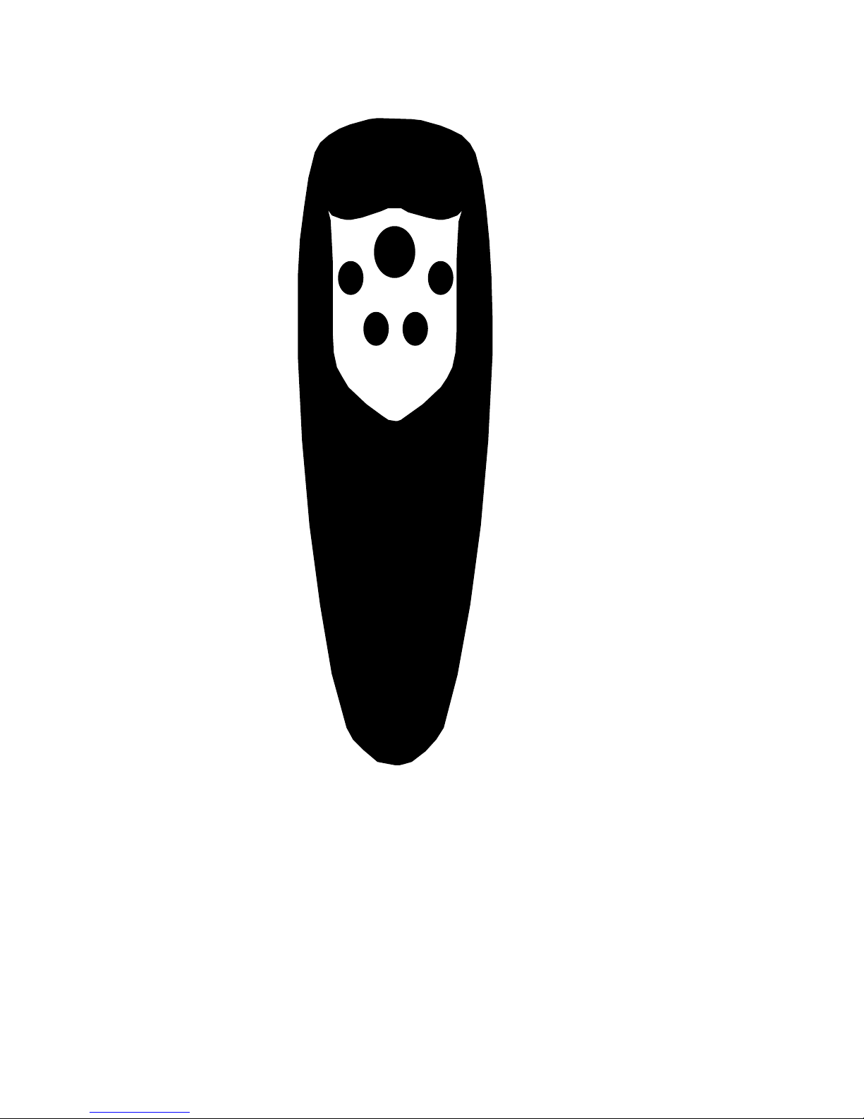
Auto Reset button on the Remote Control is the large button indicated in figure 4.
4.3 RS-232/422 Control
All of the functions detailed in section 3.1 are available from RS-232/422 control. Every TView Pro AV 1600 is
operable in both RS-232 and RS-422, but must be correctly set up for each standard. When configured for RS-422,
up to 8 TView Pro AV 1600s may be connected in a single RS-422 wired system. The TView Pro AV 1600s will react
to controls that are delivered to a unique address that is programmed into each TView Pro AV via the Front Panel
control.
When configured for RS-232, only a single TView Pro AV 1600 may be attached to the RS-232 link. The default
configuration is RS-232. You must program an address for a Pro AV 1600 connected with the RS-232, even though
only one unit may be connected in an RS-232 configuration.
TView Pro AV 1600 User's Manual Rev 1.02
22
Page 23
Reset
Size/Position
Freeze Frame UnderScan
Flicker Filter
Figure 4: Remote Control Interface
TView Pro AV 1600 User's Manual Rev 1.02
23
Page 24

4.3.1 Configuring the TView Pro AV for RS-232 or RS-422
Jumper JP3 on the TView Pro AV 1600's Control Interface board selects RS-232 or RS-422. Depending on the
configuration of this jumper, the DB-9 communications connector located on the rear panel of the TView Pro AV 1600
will accept either RS-232 or RS-422.
Figure 5 indicates the positioning of Jumper JP3. In the case of RS-422, the user has the additional choice of
selecting a 120 Ohm termination.
P1
JP3
U3
Y1
FAB 0082-1100-101
RS-232
P1
JP3
U3
Y1
FAB 0082-1100-101
RS-422 (Unterminated)
P1
JP3
U3
Y1
FAB 0082-1100-101
RS-422 (120 Ohm Termination)
Figure 5: Position of Jumper JP3 for RS232 or RS422 Control
TView Pro AV 1600 User's Manual Rev 1.02
24
Page 25
4.3.2 Connecting the TView Pro AV 1600 to communications devices
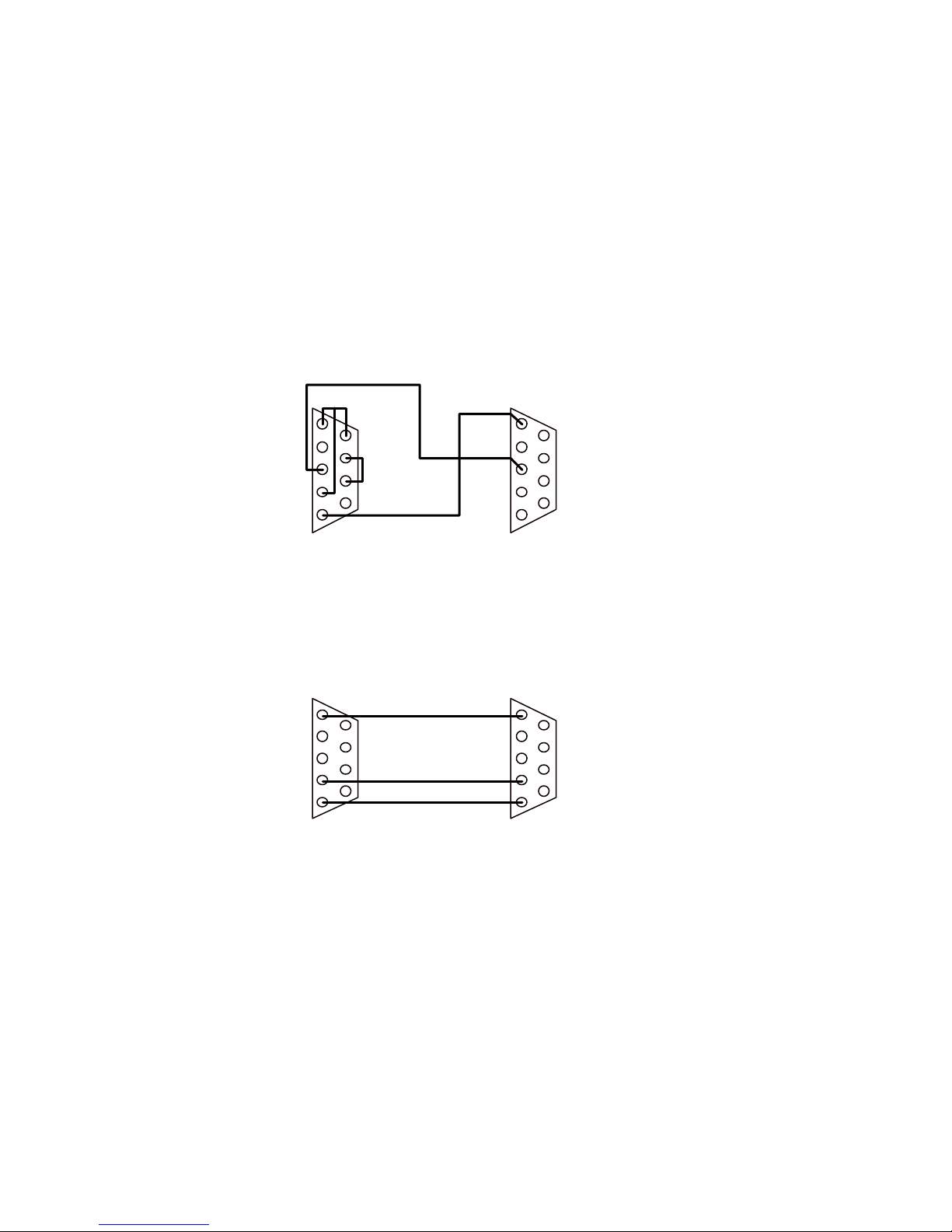
Slightly different connections schemes are required for RS-232 and RS-422 operation.
Figure 6 indicates the recommended connections from a DB-9 connector for RS-232 operation. Depending on the
way that the controlling port is programmed, other connections may work as well. The TView Pro AV 1600 has no
way of handling the RTS/CTS and DSR/DCD signals.
Figure 7 indicates the recommended connections from a DB-9 connector for RS-422 operation. In this case, a simple 9
pin to 9 pin cable will work in all cases.
1 DCD
3 Data
4 RTS
5 Ground
Computer
6 DSR
7 RTS
8 CTS
1 Ground
3 Data
Pro AV 1600
Figure 6: Recommended RS232 Wiring
1 Ground
4 TX Data +
5 TX Data -
Computer
1 Ground
4 RX Data +
5 RX Data -
Pro AV 1600
Figure 7: Recommended RS422 Wiring
TView Pro AV 1600 User's Manual Rev 1.02
25
Page 26

4.3.3 Selecting the TView Pro AV 1600's address
In an RS-422, there may be as many as 8 TView Pro AV 1600s operating within a system. In order to provide a control
mechanism to differentiate each TView Pro AV 1600, the user must program each TView Pro AV 1600's address using
the Front Panel.
Programming the address is a simple procedure. Turn the TView Pro AV 1600 on, or cycle the control sequence such
that the Power Up Identification is visible (i. e. Model 1024 or Model 1600) on the LED display. Press the Right
Arrow Button. You will see the TView Pro AV 1600’s address indicated on the LED display. When you are finished,
press either the + button or the - button. The TView Pro AV 1600 will remember its address until you change it in the
same fashion.
The address circuitry is active even you are using the RS-232 link (which does not permit multiple Pro AV 1600s or
other devices to be connected in a multiple unit configuration). The default address is 0.
4.3.4 Sending Communications Commands to the TView Pro AV 1600
The serial port of the TView Pro AV accepts serial data at 9600 baud, 8data bits, no parity bit, 1 stop bit. It is
essential that the serial communications device that delivers commands to the Pro AV 1600 be set up in this fashion.
The TView Pro AV 1600 accepts 8 bit characters as commands. The commands to turn the TView Pro AV 1600 on
and off are received as strings of ASCII alphabetic characters and binary numbers. For the purposes of this manual,
all ASCII characters and binary numbers will be referred to with the decimal numbering sequence (i. e. the minimum
value of a byte is 0, the maximum value of a byte is 255, the value of an upper case A is 65).
The Command sequence for communicating with the TView Pro AV 1600 is as follows:
1) The Activation Command is given. The Activation Command consists of the character string: HCRONx
(where x is the address of the TView Pro AV 1600). The Activation Command (and all other commands) must be
followed by a Carriage Return (ASCII character value of 13 decimal) to be accepted.
The following byte string (using decimal values for ASCII characters) indicates a valid Activation Command for a
TView Pro AV 1600 previously programmed to be address 3:
72 67 82 79 78 51 13
H C R O N 3 <CR>
Note that the address number may be delivered as either ASCII, (decimal 51 in the above case) or binary (ETX or
Control C in the above case).
If the TView Pro AV 1600 receives any unexpected input before the reception of the Activation Command, it will
ignore it. If it receives an unexpected byte during the transmission of the Activation Command, the Activation
Command must be re-transmitted (the Activation sequence is reset).
2) Individual Commands are given. Any number of commands may be given after the TView Pro AV 1600 is
activated. The TView Pro AV 1600 individual commands consist of 2 byte strings. Each 2 byte string is an internal
Register Number Byte (23 registers exist) followed by a Value Byte. The Value Byte has a different meaning and legal
TView Pro AV 1600 User's Manual Rev 1.02
26
Page 27

range for each register. Each command ( i. e. Register Number Byte, followed by Value Byte) must be concluded with
a Carriage Return.
The Value Byte provides “absolute information” if the parameter in question is a Toggle or Multiple Choice Item. If
the parameter in question is a range item, the Value Byte provides “relative information” incrementing or
decrementing the existing value of that parameter by on count.
In addition to the above commands, two additional commands are provided for control information. Writing Value
Byte = 01 to register 22 will cause an Auto Reset operation to occur. Writing Value Byte = 01 to register 23 will cause
the existing parameter set to be written in to NOVRAM. The TView Pro AV 1600 will power up with these parameters
until the NOVRAM is changed by writing another set of parameters.
The following table indicates the Register Functions, the Register Number, Parameter Type and action of the legal
values of the Value Byte.
Register Name Number Type Value Byte Actions
Horizontal Position 1 Range =01 increment, =00 decrement
Horizontal Size 2 Range =01 increment, =00 decrement
Vertical Position 3 Range =01 increment, =00 decrement
Vertical Size 4 Range =01 increment, =00 decrement
Zoom 5 Toggle =01 Zoom On, =00 Zoom Off
UnderScan 7 Toggle =01 UnderScan, =00 OverScan
Terminate 8 Toggle =01 Terminated, =00 Unterminated
Fine Genlock H Position 9 Range =01 increment, =00 decrement
Coarse Genlock H Position 10 Range =01 increment, =00 decrement
Genlock Subcarrier Phase 11 Range =01 increment, =00 decrement
Genlock Subcarrier Phase Reverse 12 Toggle =01 180 degrees, =00 0 degrees
Genlock Termination 13 Toggle =01 Terminated, =00 Unterminated
NTSC/PAL 14 Toggle =01 NTSC, =00 PAL
Flicker Filter 15 Multiple =00 Off =07 Maximum
Brighntess Boost 17 Toggle =01 Boost On, =00 Boost Off
Freeze Frame 19 Toggle =01 Freeze, =00 Live Input
YUV/RGB Selection 20 Toggle =01 RGB, =00 YUV
Sync Selection 21 Multiple =01 GRN, =02 VGA, =03 MAC
Reset 22 =01 Reset
NOVRAM Save Parameters 23 =01 Save
Keyboard Lock 24 Toggle =00 Unlocked =01 Locked
IR Remote 25 Toggle =00 Disabled =01 Enabled
Test Pattern 26 Toggle =00 Disabled =01 Enabled
Brightness 27 Range 0-127
Contrast 28 Range 0-127
Saturation 29 Range 0-127
TView Pro AV 1600 User's Manual Rev 1.02
27
Page 28

For example, the following byte sequences perform the indicated functions:
Output Set to PAL
14 0 13
NTSC/PAL register 0, therefore PAL <CR>
Decrement Horizontal Size
2 0 13
Horizontal Size Decrement by 1 <CR>
Delay time between each transmitted character of a command does not matter. Each command will not be completed
until the Carriage Return is received. If incorrect register numbers are given at the start of any command (i. e. byte
with a register value greater than 23), the TView Pro AV 1600 will ignore that byte.
Special caution should be used when using the Save Settings Command (Register 23). Excessive repeated use of this
command (i. e. inside an endless loop) will damage the TView Pro AV 1600's Non-Volatile memory.
3) The De-Activation Command is given. When a TView Pro AV 1600 is used in an RS-422 system with several
other TView Pro AV 1600s, it will be necessary to De-Activate the currently selected TView Pro AV to issue
commands to another TView Pro AV 1600 in the system. If you are using a single TView Pro AV 1600, it will not be
necessary to De-Activate the TView Pro AV 1600.
The De-Activation Command consists of the character string: RSOFFx (where x is the address of the TView Pro AV
1600). The De-Activation Command (and all other commands) must be followed by a Carriage Return (ASCII
character value of 13 decimal) to be accepted.
The following byte string (using decimal values for ASCII characters) indicates a valid De-Activation Command for a
TView Pro AV previously programmed to be address 3:
82 83 79 70 70 31 13
R S O F F 3 <CR>
Note that the address number may be delivered as either ASCII, (decimal 51 in the above case) or binary (ETX or
Control C in the above case).
If the TView Pro AV 1600 receives any unexpected input before the reception of the De-Activation Command, it will
ignore it. If it receives an unexpected byte during the transmission of the De-Activation Command, the DeActivation Command must be re-transmitted (the De-Activation sequence is reset).
TView Pro AV 1600 User's Manual Rev 1.02
28
Page 29

5 Hyperformance Utility Software
A DOS test program for IBM PCs, entitled Hyperformance, can be downloaded from the FOCUS Enhancements web
site. If you would like to obtain a copy of Hyperformance, please log onto www.focusinfo.com. The
Hyperperformance software is available at the downloads page which is in the Tech Support section of the website.
5.1 Hyperformance Components
Hyperformance Software consists of a DOS application program with some sample images.
The release contains the following files:
Hyperformance Test Software Disk
HYPER.EXE Hyperformance Test Software
PICTURE8.PCX A 256 color image
PICTURE4.PCX A 16 color image
5.1.1 Installing and Running Hyperformance Tests Software
To install the software, copy the contents of the Hyperformance PC Test Software diskette to your hard disk, as
follows:
COPY A:*.* C: or B:*.* C:
This command should copy HYPER.EXE, PICTURE8.PCX, and PICTURE4.PCX to your hard disk.
To execute the program, type "HYPER".
5.1.2 The Main Menu
Upon execution, the utility software displays the following menu:
PRO AV UTILITY SOFTWARE
1 Text Mode 720 x 400 (Mode 3 hex)
2 16 color 640 x 350 (Mode 10 hex)
3 16 color 640 x 480 (Mode 12 hex)
4 256 color 320 x 200 (Mode 13 hex)
5 16 color VESA 800x600 (Mode 102h)
6 256 color VESA 800x600 (Mode 103h)
7 16 color VESA 1024x768 (Mode 104h)
8 256 color VESA 1280 x 1024 (Mode 107H)
I Images
C Change Menu Color
S Clear Screen
M Display Menu
Q Quit
TView Pro AV 1600 User's Manual Rev 1.02
29
Page 30

Commands 1-8 set the Video Mode. The current video mode is always displayed at the bottom of the screen. The
default video mode is Mode 12 Hex: 16 Color, 640 columns by 480 rows.
I clears the screen and displays the Image Menu (see below).
C clears the screen and displays a menu which allows you to select a
different color for the menus (press ESC to leave this menu
without changing the menu color).
S clears the VGA screen of image and text.
M redisplays the menu.
Q leaves the utility software and returns to DOS.
5.1.3 The Image Menu
PRO AV TEST IMAGES
T Page of Text
C Color Bars
H Chirp
P Pattern
I Picture
A Ramp
K Chroma Key Chart
M Menu
S Clear Screen
R Return
T Displays a Page of Text.
C Displays eight vertical color bars.
H Displays a Chirp Pattern.
P Displays a Complex Black and White
Pattern.
I Displays a 16 or 256 color picture
(the full picture is seen only in the
1024 x 768 mode; smaller resolutions
display the upper left hand corner of
the picture).
A Displays a 16 or 256 grey shades ramp.
K Displays a 16 or 256 color grid.
M Redisplays the Image Menu.
S Clears the screen.
R Returns to the Main Menu.
5.1.4 Hyperformance Utility Software Error Messages
5.1.4.1 Not a Legal Command in TEXT MODE
The Page of Text is the only Image that can be displayed in Text mode. This error message will be displayed if you
try to display any of the other Images in Text mode.
TView Pro AV 1600 User's Manual Rev 1.02
30
Page 31

5.1.4.2 Picture8.PCX Not Found!
Picture8.PCX contains the Picture displayed in the 256 color modes. If this error message occurs, make sure the file
PICTURE8.PCX is present in the current directory.
5.1.4.3 Picture4.PCX Not Found !
Picture4.PCX contains the Picture displayed in the 16 color modes. If this error message occurs, make sure the file
PICTURE4.PCX is present in the current directory.
5.1.4.4 VESA Version n.n VESA CALL FAILED
This error occurs when the VESA driver with the indicated version number has been installed, but a call to the VESA
software returns an error code. It indicates an incompatibility between the VESA driver and the VGA card.
5.1.4.5 VESA Driver Not Installed
The utility software uses the VESA TSR in the 1024x768 and 800x600 modes. If your attempt to use these modes
results in this error message, make sure you have installed the VESA TSR (see above).
TView Pro AV 1600 User's Manual Rev 1.02
31
Page 32

Appendix A - Limited Warranty
FOCUS Enhancements, Inc. warrants this product against defects in materials and workmanship for a period of THREE (3) YEARS
from the date of original purchase.
If you discover a defect, FOCUS Enhancements, Inc. will, at its sole option, repair or exchange the product at no charge to you,
provided you contact FOCUS Enhancements, Inc. Technical Support to obtain a Return Material Authorization (RMA) Number and
instructions on where and how to obtain repair. Note that a copy of the bill of sale bearing the FOCUS Enhancements, Inc. serial
numbers as proof of date of original purchase is required for each product returned for warranty service. Before returning product,
remove all non-FOCUS Enhancements, Inc. RAM, accessories, and options. FOCUS Enhancements, Inc. cannot be liable for the
return or care of any non-FOCUS Enhancements, Inc. products, nor accept responsibility for loss or damage of product in transit.
This warranty does not apply if the product has been damaged by accident, installation or removal of product, abuse, misuse,
misapplication, accident, neglect, fire, water, lightening, or other acts of nature, failure to follow supplied instructions; has been modified,
repaired or undergone attempted repair by unauthorized personnel without the written consent of FOCUS Enhancements, Inc.; has a
serial number that has been removed, modified, or defaced. FOCUS Enhancements, Inc. reserves the right to use re-manufactured,
refurbished, or used parts and components in making warranty repairs.
FOCUS Enhancements, Inc. products are designed to work with Windows and MacOS computers. Certain features of third-party
software or hardware designed for the host system may not be available when used with this product. Accordingly, FOCUS
Enhancements, Inc. does not warrant or represent that all third-party software or hardware will function error-free when used in
conjunction with this FOCUS Enhancements, Inc. product.
THIS WARRANTY IS IN LIEU OF ALL OTHER WARRANTIES, WHETHER ORAL OR WRITTEN, EXPRESS OR IMPLIED. ALL
EXPRESS AND IMPLIED WARRANTIES OF MERCHANTABILITY AND FITNESS FOR A PARTICULAR PURPOSE, ARE
LIMITED IN DURATION TO THE WARRANTY PERIOD. NO WARRANTIES, EXPRESS OR IMPLIED WILL APPLY AFTER THIS
PERIOD. FOCUS ENHANCEMENTS, INC. SHALL NOT BE LIABLE FOR ANY LOST PROFITS, DAMAGE TO OTHER
PROPERTY CAUSED BY A DEFECT IN THIS PRODUCT, DAMAGES BASED UPON INCONVENIENCE, LOSS OF USE OF
THE PRODUCT, LOSS OF TIME, COMMERCIAL USE, INCIDENTAL AND/OR CONSEQUENTIAL DAMAGES FOR THE
BREACH OF ANY EXPRESS OR IMPLIED WARRANTY, INCLUDING DAMAGE TO PROPERTY AND, TO THE EXTENT
PERMITTED BY LAW, DAMAGES FOR PERSONAL INJURY, EVEN IF FOCUS ENHANCEMENTS, INC. HAS BEEN ADVISED
OF THE POSSIBILITY OF SUCH DAMAGES.
Some states do not allow the inclusion or limitation of incidental or consequential damages or limitations on how long an implied
warranty lasts, so the above limitation or exclusion may not apply to you. This warranty gives you specific legal rights, and you may
have other rights, which vary, from state to state.
TView Pro AV 1600 User's Manual Rev 1.02
32
Page 33

Appendix B - Hyperformance Utility Software License
FOCUS Enhancements Corporation grants the user a 99 year license to use and reproduce the Hyperformance Utility
Software. No restrictions in copying or using the software or its reproduced images are implied except that any video
taped reproduction of any image developed or displayed by the Hyperformance Utility Software must be reproduced
using a FOCUS Enhancements Pro AV 1600 product.
TView Pro AV 1600 User's Manual Rev 1.02
33
Page 34

Appendix C – Genlock
All versions of the Pro AV 1600 can Genlock to a black burst, or active video external reference signal. Our usage of
the word Genlock is the usage understood by professional Television Engineers. The Pro AV 1600 will lock
Vertically, Horizontally and in color phase to the external reference signal. All Overlay, Chroma-Key, mixing
functions, etc. must be accomplished by additional devices.
The suggested way to align Genlock is as follows:
Make sure that the Pro AV 1600 provides a properly aligned picture with respect to an ordinary television raster.
(Since you have control over Horizontal and Vertical Size and Position, all 4 of these parameters must be properly
aligned with a television raster before attempting Genlock).
Connect the Genlock reference signal into either one of the Genlock BNC connectors. Connect the other Genlock
connector to the next device that you want to provide Genlock reference to. If the TView Pro AV 1600 is the last
device in the configuration, select the Genlock Termination On from the Front Panel or RS-232/422 Communication.
Otherwise, make certain that you select Genlock Termination Off. The 2 Genlock connectors are directly connected
with no buffering.
Adjust the Genlock Horizontal Position (from the front panel or RS-232/422) for correct position of the converted
video signal at the mixing point.
Adjust the Genlock Color Phase (from the front panel or RS-232/422) for the correct color phase of the converted
video signal at the mixing point.
TView Pro AV 1600 User's Manual Rev 1.02
34
Page 35

Appendix D - Component output
All versions of the Pro AV 1600 support two user selectable forms of component output. The TView Pro AV 1600 is
factory configured for Betacam component (Y, R-Y, B-Y) and RGB (without 7.5 IRE units of video setup). In addition,
component output synchronization may be provide as a separate, composite sync signal (4 wire) or as composite
sync signal on the green output (3 wire). Other amplitudes of component output ( i. e. M II) are available by special
order.
TView Pro AV 1600 User's Manual Rev 1.02
35
 Loading...