

Page 1

TView Micro
User’s Guide
Rev. 04/02
Page 2

FCC NOTICE
This equipment has been tested and found to comply with
the limits for a Class B digital device, pursuant to Part 15
of the FCC Rules. These limits are designed to provide
reasonable protection against harmful interference in a
residential installation. This equipment generates, uses
and can radiate radio frequency energy, and if not
installed and used in accordance with the installation
manual, may cause harmful interference to radio
communications. However, there is no guarantee that
interference will not occur in a particular installation. If this
equipment does cause harmful interference to radio or
television reception, which can be determined by turning
the equipment on and off, the user is encouraged to try to
correct the interference by one or more of the following
measures:
• This unit was tested with shielded cable. Therefore,
for continued compliance, use the shielded cables
provided with the unit.
• Re-orient or relocate the unit or receiving antenna.
• Increase the separation between the
computer/converter and television.
• Connect the equipment to an outlet on a circuit
different from that to which the receiver is connected.
• Consult the dealer or an experienced radio/TV
technician for help.
You may find the following booklet helpful:
How to Identify and Resolve Radio-TV Interference
Problems (stock number 004-000-000345-4)
Page 3

To order the booklet, write to:
The U.S. Government Printing Office
Washington D.C. 20402
COPYRIGHT
This document and the software described in it are
copyrighted under United States Copyright Laws. No part
of this document or software may be copied without prior
written consent from FOCUS Enhancements, Inc. except
in the normal use of the software as described in this
documentation. All printed circuits, their physical
implementation on printed circuit boards and associated
software are copyrighted with all rights reserved. Under
the copyright laws, the printed circuit board, or the
software programs provided may not be copied in whole
or part, without written consent of FOCUS
Enhancements, Inc., except in the normal use of the
software programs to make a backup copy. This
exception does not allow copies to be made for others,
whether sold or not, but all of the material may be sold,
given, or loaned to another person. Under the law,
copying includes translating into another language or
format.
Microsoft Windows, Windows 95, 98, 2000, ME, NT, XP
and Microsoft are trademarks of Microsoft Corporation.
All other products named are trademarks of their
respective manufacturers.
©2002 FOCUS Enhancements, Inc. All Rights Reserved
Page 4

This is a blank page
Table of Contents
CHAPTER 1 4
CHAPTER 2 10
Checking the Packing List 11
Packing List 11
Inspecting the Equipment 12
CHAPTER 3 22
Windows 95, 98, NT, 2000, ME & XP 25
Macintosh 25
Configuring the Macintosh Monitor Mode 26
CHAPTER 4 28
Brightness 29
Color 29
Sharpness 29
Tint or Hue 29
CHAPTER 5 30
Page 5

About the User’s Guide
The TView Micro User’s Guide is designed to help you to
quickly and easily connect the hardware and install the
software for this product. The guide is divided into the
following chapters:
Chapter 1: Introduction: which describes the key
features and functionality of the product and some of its
many uses. The chapter also discusses the notation
conventions used in the guide.
Chapter 2: Installing the Hardware: which
describes the information you should know before
installing and connecting the TView Micro hardware, and
the steps required to perform the installation.
Chapter 3: Image Control: describes the location
and functions of the control buttons on the TView Micro
unit and the auto-save memory function. It also describes
the steps involved in configuring your PC or laptop video
output.
Chapter 4: Tuning Your Television: this chapter
describes the methods you can use to tune the image on
your television.
Chapter 5: Troubleshooting: describes possible
problems that you might encounter and ways to solve
them.
Preface
1
Page 6
TView Micro User’s Guide
Notation Conventions
This user’s guide uses the following conventions to
specify certain types of information.
Warns you about potential problems
and hazards during the installation or
use of the product. Read these
warnings carefully, and be sure you
understand how they relate to the
installation procedures before
proceeding.
Note: Points out important or useful information.
Contact Information
To get information on the reseller nearest to you, to order
replacement parts, or for technical support contact one of
the following:
Focus Enhancements
Worldwide Headquarters
1370 Dell Avenue
Campbell, CA
Customer Service 800-338-3348 (U.S. Only)
Technical Support 408-370-9963
About This Guide
2
Page 7

Page 8

TView Micro User’s Guide
Chapter 1
Introduction
The TView Micro converts the VGA output from your
computer into video that can be displayed on a television
or recorded to a VCR. TView Micro automatically detects
VGA, SVGA, and XGA resolutions and synchronizes
them with your television. The result is a high quality,
flicker-free television display from your computer.
Features
The TView Micro includes the following features:
• Contains the industry leading FS 400 Chip which
provides the best possible resolution for PC-to-TV
scan conversion
• Plug and play pure hardware design
• Support for 640 x 480 800 x 600 and 1024 x 768
resolution at frequencies up to 152Hz
• Supports NTSC or PAL systems ( Two versions sold
seperately)
• Supports Composite and S-Video
• Manufacture default reset
• Power consumption from PC’s keyboard or USB port
• Compatibility with any size television monitor
(NTSC/PAL) with an RCA (composite), S-Video input
connection (Pending purchase of NTSC or PAL unit)
Introduction
4
Page 9

• Works with multiple platforms including Mac OS 7.1
or higher, Microsoft Windows 95, 98 , NT, 2000 and
ME
• 8 Levels of Brightness Control along with 8 Levels of
Sharpness and Flicker Filter
• 8 Levels of Over/UnderScan and Horizontal/Vertical
Scan
• EE-ROM auto save TV-Position and Size
• Zoom/Pan and freeze/unfreeze
• 2D Flicker Filter with 8 Levels
• Auto power on/off
• VGA to SCART adapter for PAL version
Chapter 1
5
Page 10

TView Micro User’s Guide
Modes of Operation
The TView Micro has ability to operate in three separate
modes:
1. Presentation Mode: Display the same image on your
computer
2. Television Only Mode: Use the television as your only
display.
3. Video Record Mode: Record your video image
directly to videotape.
Introduction
6
Page 11
AV
AV
S
CARD
A
G
V
AV
ENC
O
DER
R
O
NT
O
M
VGA
SIZE
PICTORE
TV SHOW
HSIZE/BRIGHT
ZOOM
VXIZE/FLICKER
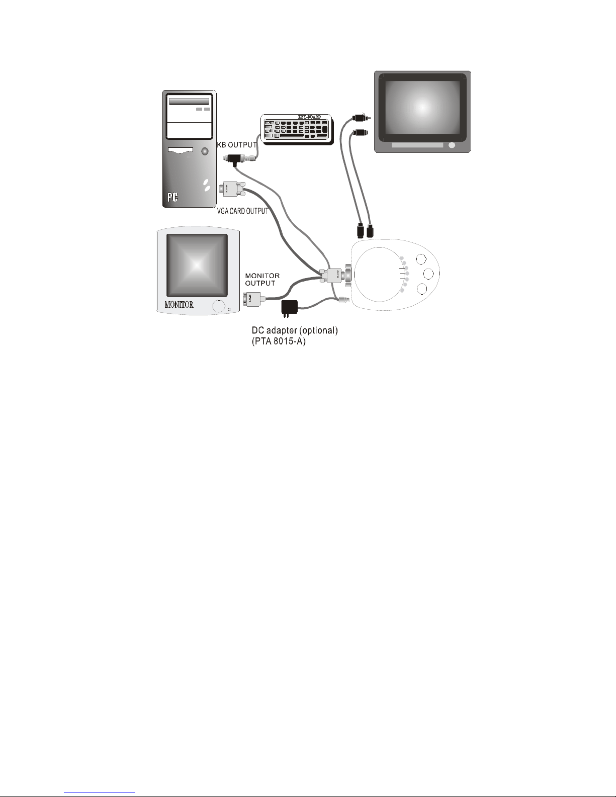
Figure 2-1: Connecting TView Micro to the Television
& Computer
Note: You have the option to use either the USB or
PS2/AT power cables, which are both included inside.
The DC adapter is not included but can be purchased
through our customer service.
Chapter 1
7
Page 12

TView Micro User’s Guide
Suggested Uses for the TView Micro
The TView Micro can be used for many purposes. For
example:
• Bring sales or other multimedia presentations from a
laptop to a large TV
• Create training tapes or outfit a training room
• Demonstrate a new software package using a large
screen TV
• Project computer games onto a TV screen
• Cruise the Internet on a TV
• Conferencing via TV
• E-Mail
• Collaborating with others on computer-based projects
• View DVD movies from your computer on your TV
Introduction
8
Page 13
Specifications
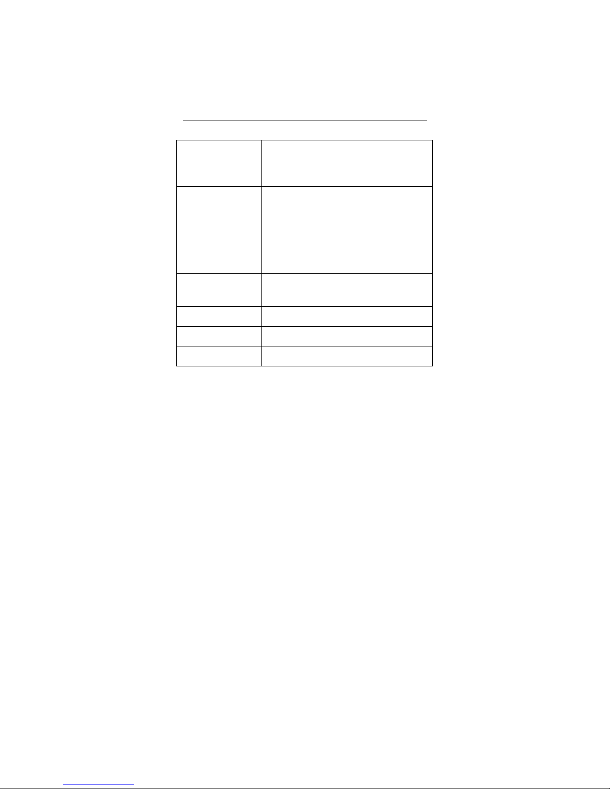
Table 1: TView Micro Specifications.
Computer
Compatibility
• Multiple platforms include Mac OS,
Windows 95, 98, 2000 , ME & XP along
with any computer with a VGA output
Television
Compatibility
Color Modes and
Resolution
Power Supply • Powered by keyboard or USB port
Unit Weight • 10.9 ounces (withcables)
Unit Dimensions • 4.5 cm x 3cm x 3.5 cm
• Works with any size television monitor
(NTSC or PAL) with an RCA (composite),
S-Video input connection. For television
receivers or televisions without composite
or S-Video inputs, an RF Modulator is
required (Radio Shack #15-1283)
• Supports up to 16,777,216 colors (24-bit),
and up to 1024 x 768 152Hz
Chapter 1
9
Page 14

TView Micro User’s Guide
Chapter 2
Hardware Installation
This chapter describes the information you should know
before installing and connecting the TView Micro
hardware, and the steps required to perform the
installation.
System Requirements
Before installation, the following are system requirements
for the operation of the TView Micro:
IBM (or compatible)
• Personal or multimedia computer with a 486 or higher
processor
• Microsoft Windows 95, 98, NT, 2000, ME & XP
• VGA, SVGA, or XGA desktop resolution
Macintosh (or compatible)
• Macintosh Performa or PowerMac with a 68020 or
higher processor
• MacOS System Software 7.1 or higher
• VGA, SVGA, or XGA desktop resolution
Hardware Installation
10
Page 15

Note: In order to see the video output on both the
computer monitor and TV simultaneously, you
will need to be using a monitor with a VGA
compatible input connector. If your monitor is
larger than 14”, it must be multisync (capable
of running at various frequencies). Refer to
your Macintosh documentation if you have any
questions Macintosh documentation if you
have any questions regarding the type of
monitor you are using.
• A TV/monitor, VCR or any video device that can
display or record NTSC or PAL video.
Checking the Packing List
Check the packing list that is included in this manual.
Compare the list with the equipment you have purchased.
Be sure that you have received everything that is on the
list. If anything is missing, contact FOCUS Enhancements
Customer Service department by calling 1-800-338-3348.
Packing List
Your TView Micro includes the following items:
• TView Micro (NTSC or PAL version sold seperately)
• Keyboard power cable (PS2/AT)
• 1 S-Video and 1 Composite video cable (connected
to unit)
• User’s guide and QuickStart guide (on CD ROM)
• DC Power Adapter (not included but optional)
Chapter 2
11
Page 16

TView Micro User’s Guide
• USB power cable
• VGA to SCART video adapter (included
internationally only)
Inspecting the Equipment
Before installing and connecting the hardware, inspect it
for any damage, which may have been incurred during
shipment. Perform a thorough inspection, looking for
dents, scratches, or loose parts. Look for anything that
appears unusual or out-of-the ordinary. If any of the
equipment is damaged, contact FOCUS Enhancement’s
Customer Service department by calling 1-800-338-3348.
Connecting the TView Micro to an IBM
PC or Macintosh Computer
This section describes the steps to connect your TView
Micro to a television or VCR. The following sections
describe how to connect to IBM PCs, Macintosh PCs,
IBM PC laptops and Notebooks, and Macintosh
PowerBooks.
Hardware Installation
12
Page 17

Notes: 1. Before performing the steps to
connect the TView Micro to a laptop computer,
you must turn on the external video connector.
This is accomplished by using a particular key
sequence on the keyboard (for example, FN +
F11) or through the BIOS setup program. Refer
to your laptop owner's manual to determine
how the external video connector is turned on.
2. Ensure that you are using a Macintosh
PowerBook computer that has a connector for
an external monitor.
Perform the following steps to connect the TView
Micro to a PC or Macintosh Desktop or Laptop:
1. Turn the computer and monitor off.
The computer must be off when connecting
the TView Micro. Connecting with the power
on could result in static damage to your
computer and video equipment.
2. Disconnect the current monitor cable from the
"monitor out" port at the rear of the computer.
3. Locate the Video In cable attached to the rear of the
TView Micro unit.
4. For an IBM PC or compatible, connect the cable
connector located at the other end of the VGA Input
Chapter 2
13
Page 18

TView Micro User’s Guide
cable to the "monitor out" port at the rear of the
computer, the same port from which you
disconnected the current monitor cable in step 2. For
an older Macintosh model or compatible, you may
use a Macintosh video adapter, connect the other
end of the VGA Input cable to the Macintosh Video
Output port located at the rear of the computer, the
same port from which you removed the current
monitor cable in step 2.
5. Connect the male end of your computer’s monitor
cable to the female connector on the VGA input
cable.
6. Connect the composite or S-Video cable from the
TView Micro to the TV.
7. Connect the PS2/AT power cable to the keyboard
port and the other end to the PC keyboard port.
(Option to use the USB power cable and connect it to
the USB port instead)
8. Once complete you will be able to view the PC
monitor on your TV.
Hardware Installation
14
Page 19
2.1 TView Micro OUTLINE DESCRIPTION
FREEZE/Un FREEZE
DC/KB
KB power cable
(PTA 8015)
UP-KEY DOWN-KEY
VSIZE/FLICKER
VGA
ZOOM
HSIZE/BRIGHT
SIZE
PICTORE
LEFT KEY
PIC/SIZERIGHT KEY
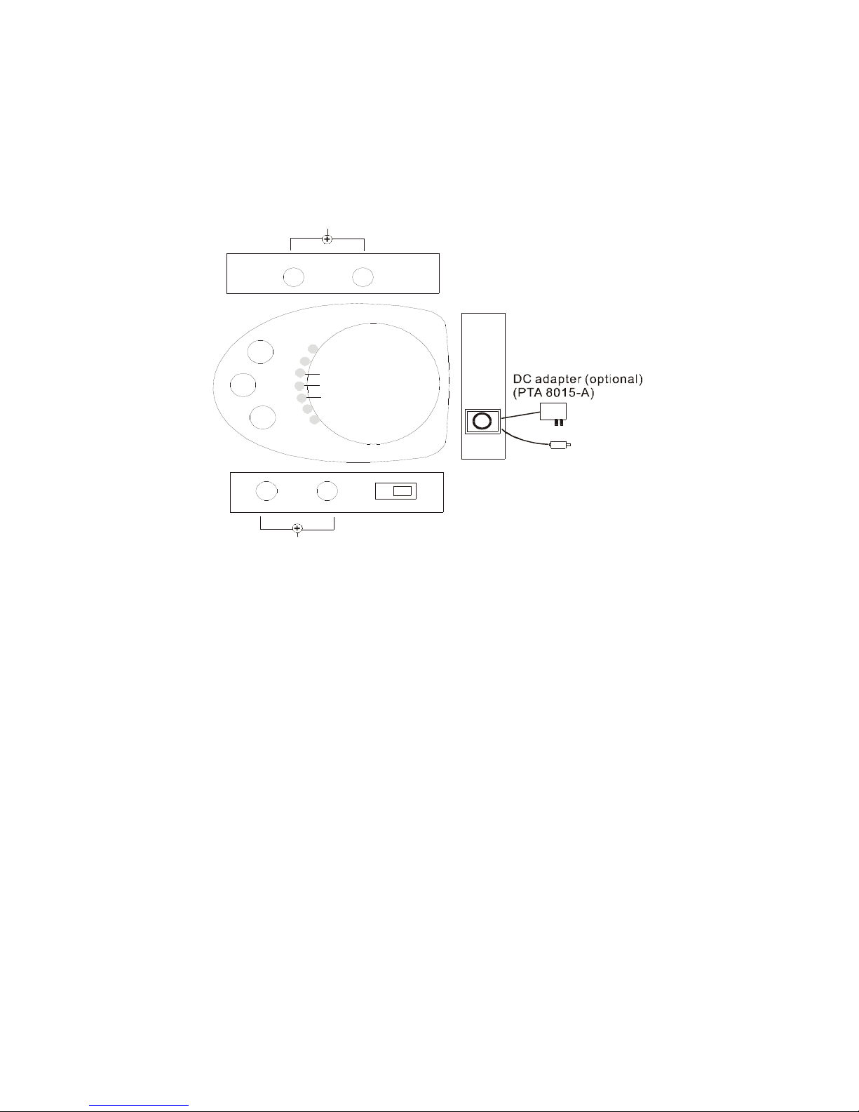
Figure 2-1: Connecting the TView Micro XGA to an IBM or Macintosh PC
Chapter 2
15
Page 20
TView Micro User’s Guide
Note: You have the option to use either the supplied
keyboard PS2/AT or USB power cable. You can
purchase the DC power cable through our customer
service.
Connecting the TView Micro to a
Television
The next step in connecting your system is to connect it
to the television. (If you are planning to connect to a VCR,
see "Connecting to a VCR" below.) There are two
possible ways to connect to a television:
• Using a composite video connection
• Using an S-Video connection
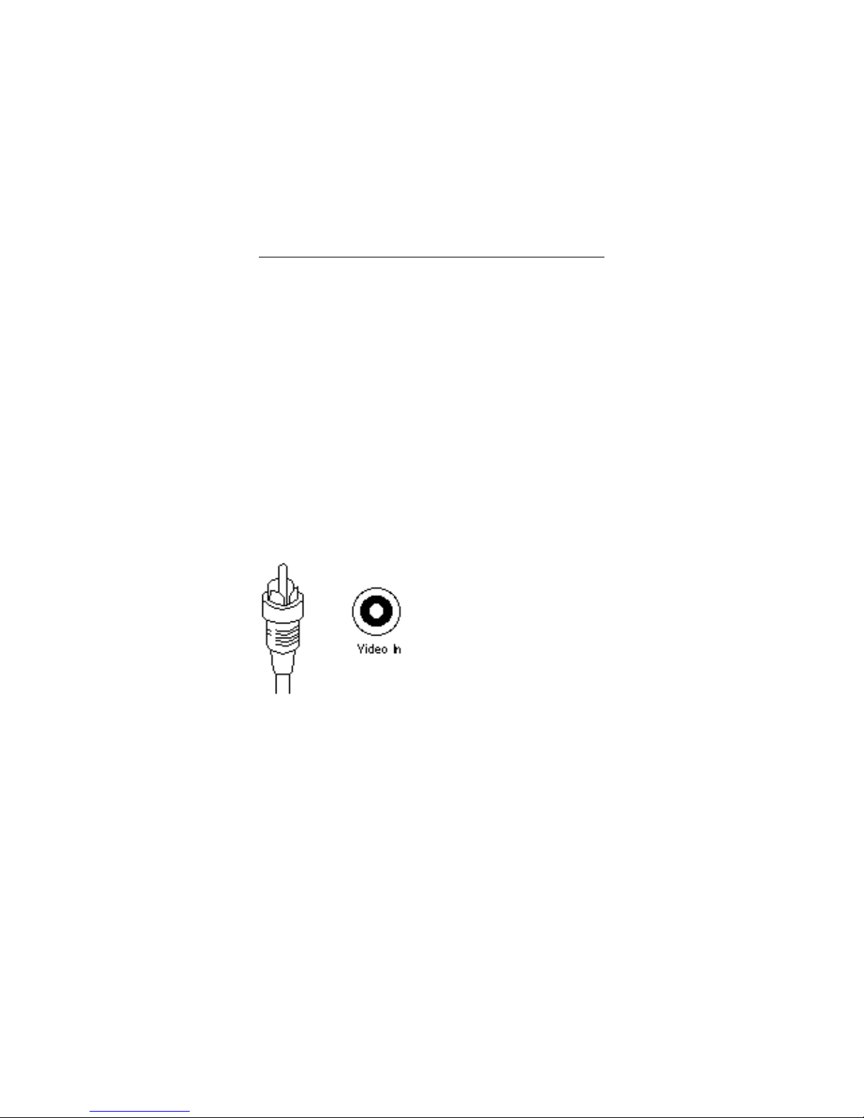
Composite Video Connection
Composite video is a connection type used by most
televisions, VCRs, laserdisc players, and certain LCD
panels. The connectors on a composite video cable have
an RCA-type plug. The plug has a long metal pin
projecting from its center and plugs into the composite
video in port at the rear of the television.
Figure 2-3: Composite Video Connectors
Hardware Installation
16
Page 21
To determine if your television supports composite video,
look for a port on your television that matches the
composite video out port at the rear of the TView Micro
unit.
Note: The composite video port on the television may
or may not be labeled "video in.”
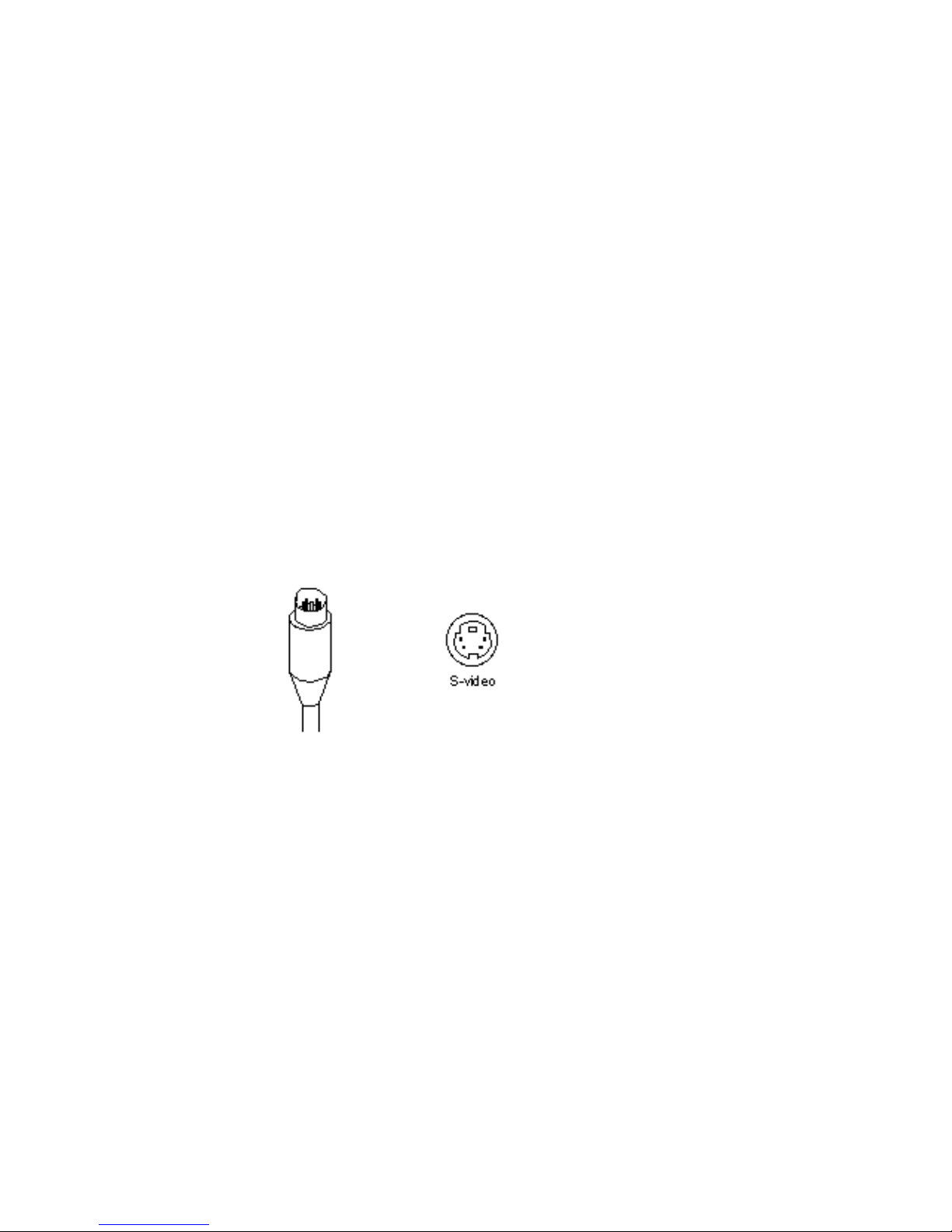
S-Video Connection
S-Video is a high-quality video connection used by some
video cameras and VCRs. The connector on an S-Video
cable has a round plug with several small metal pins. It
plugs into the S-Video output port at the rear of the TView
Micro unit.
Note: The S-Video connection is a newer video
standard. This type connection improves color,
clarity, and resolution. It is recommended that if
the S-Video connection is available it be used.
Figure 2-4: S-Video Connectors
Chapter 2
17
Page 22

TView Micro User’s Guide
To determine if your television supports S-Video, look for
a port at the rear of the television that matches the SVideo output port at the rear of the TView MicroUnit.
Note: The S-Video port on the television may or may
not be labeled "S-Video in."
To connect the TView Micro unit to your
television, perform the following steps:
1. Connect one end of the supplied composite video
cable to the “Comp Video” port located on the back of
the TView Micro unit, or connect the male end of the
S-Video cable to the port on the back of the TView
Micro. Connect the other end of the composite cable
or S-Video cable to the Comp Video in or S-Video in
port at on the television.
2. Turn the television on.
3. Turn the TView Micro on.
4. Turn your computer on. If the cables have been
connected correctly, the image from the computer
monitor should now appear on the television screen.
When you are looking at the television to make these
connections, you may see an input labeled ANT IN. This
input is used by cable TV companies and uses a different
type of video than that used by TView Micro. It is not
possible to connect directly to this input. If this is the only
Hardware Installation
18
Page 23

input available, and you do not have a VCR, this input
can be used with an RF modulator. See below for further
information.
Note: Because the port may not be labeled, you will
need to match the port to the connector you
are using.
Connecting to the Television Using an
RF Modulator
If you do not have a television with composite video or SVideo, you will need a special adapter called an RF
Modulator. This device converts the Composite Video
signal from the TView Micro unit to an antenna signal.
The RF Modulator is not supplied.
Note: When using a RF Modulator, the TV may have
to be set to a particular channel (for instance, 3
or 4) to accept the TView Micro video. Or, in
some cases, you may have to specify input
using the TVs on-screen-programming feature.
If you are unsure about how to set your
television to accept external video through the
Antenna In, refer to the television owner’s
manual.
Chapter 2
19
Page 24

TView Micro User’s Guide
To connect the TView Micro to your
television using the RF Modulator, perform
the following steps:
1. Connect the RF Modulator to the coaxial input at the
rear of the television.
2. Connect the composite video cable from the unit to
the RF Modulator’s Composite Input at the rear of the
television.
3. Plug RF modulator into wall outlet or surge protector
4. Turn your computer on.
5. Turn the TView Micro on.
6. Turn the television on. If the cables have been
connected correctly, the image from the computer
monitor should now appear on the television screen.
Connecting the TView Micro to a VCR
In certain configurations, the video will be run through a
VCR. Therefore the unit must be connected to the VCR.
By connecting the TView Micro unit, you will also be able
to record the computer screen to videotape.
To connect your TView Micro to a VCR,
perform the following steps:
1. Connect the other end of the composite cable or SVideo cable to the port at the rear of your VCR
labeled "Video Input" or “AUX-IN,” “AV-IN,” or “S-
Hardware Installation
20
Page 25

VIDEO IN.”
2. Turn on the VCR.
3. Turn on your television and tune it to channel 3 or 4.
4. Turn the TView Micro unit on.
5. Turn the computer on.
6. Find a button on the front of the VCR called "Line,"
"TV/Video," "Video Input," or something similar. Press
the button. If the cables have been connected
correctly, the image from the computer monitor
should now appear on the television screen.
Note If your VCR does not have a button specifying
video-in, use your VCR’s remote control to find
an on-screen programming system. Using the
programming system set the VCR to receive
external video. If you are unsure about how to
do this, refer to the VCR owner’s manual.
Chapter 2
21
Page 26

TView Micro User’s Guide
Chapter 3
Image Control
This chapter describes the location and functions of the
control buttons on the TView Micro Unit. It also describes
the steps involved in configuring your desktop or laptop
video output.
Screen Controls
If you look at the top of your TView Micro unit, you will
notice three buttons on top and two on the left and right
side of the unit. These buttons are used to perform
various adjustments to the unit’s video output. The
following descriptions outline the functions controlled by
each of these buttons.
The buttons on top of the TView Micro
perform the following functions:
• Flicker/ VSize Button: When the “PIC/SIZE”
switch on the right of the unit is in the PIC position,
this button is used to toggle through eight flicker
reduction modes. Click the button until the image on
your television is stable and not flickering. When the
Image Control
22
Page 27

“PIC/SIZE” switch on the right of the unit is in the
Size position, this button is used to size your
computer’s screen vertically to fit the television
screen.
• Zoom: When you choose to click on the Zoom
Button (Button 2) you can use the “Up & Down” and
“Left & Right” position buttons to move horizontally
and vertically bit by bit throughout the entire screen in
zoom mode.
• Bright/ HSize: When the “PIC/SIZE” switch on
the right of the unit is in the PIC position, this button
is used to adjust the brightness of the image. When
the “PIC/SIZE” switch on the right of the unit is in the
Size position, this button is used to size your
television screen horizontally to fit the television
screen. Pressing the “HSIZE” button incrementally
scrolls the entire image left and right on the TV.
When the image reaches the left or right of the
screen, it cycles around to the middle of the screen.
• Screen Height Control: Use the “Up” “Down”
buttons on the left side of the unit to control the
screen’s height on your television. Pressing these
buttons allows you to size your computer screen
vertically to fit the television screen.
• Screen Width Control: Use the “Left” “Right”
buttons on the left side of the unit to control the
screen’s width on your television. Pressing these
buttons allows you to size your computer screen
Chapter 3
23
Page 28

TView Micro User’s Guide
horizontally to fit the television screen.
• Default Mode: Pressing the “Left” Key plus the
“Right” Key at the same time will automatically set the
Micro unit into a Default Reset mode.
• Freeze/ Un Freeze Mode: Pressing the “ UP”
Key plus the “Down” Key at the same time will
automatically activate the function of Freeze/ Un
Freeze mode.
Auto-Save Memory Function
After you have changed the settings of the TView Micro,
the changes are automatically saved to memory with the
unit’s auto-save memory function. Each set- up will be
saved into EEROM, which means all settings will be
saved even if the unit is powered off and on.
To restore all settings to their defaults, press the left and
right key at the same time. When the buttons are
released, all settings are returned to their defaults.
Image Control
24
Page 29

Changing Screen Resolutions
Windows 95, 98, NT, 2000, ME & XP
To change screen resolutions perform the
following steps:
1. Click on the "Start" button.
2. Choose "Settings" and go to the "Control Panel"
submenu.
3. Double-click on the "Display" icon.
4. Click on the "Settings" tab.
5. Move the "Desktop Area" slider to the desired
resolution.
6. IMPORTANT: Click on "APPLY" first, and then "OK."
Macintosh
To change screen resolutions, perform the
following steps:
1. Select "Monitors and Sound" from the control panel.
2. In the resolution area of the monitor’s window, use
the "Show" pull down menu.
3. Select "Show All."
Chapter 3
25
Page 30

TView Micro User’s Guide
4. Select the desired resolution.
Configuring the Macintosh Monitor
Mode
Most Macintosh PowerBook’s allow you to configure the
external monitor in two ways:
• Mirror Mode - The external monitor reflects
whatever appears on the PowerBook screen.
• Dual Monitor Mode - The external monitor
increases the size of the workspace, allowing you to
drag windows or applications from one monitor to
another.
Note: Newer PowerBook’s such as the 2400s and
3400s do not support dual monitor mode.
When the TView Micro is connected to these
models, it defaults to external monitor mode,
and the PowerBook’s internal screen is turned
off.
When the TView Micro is connected to the PowerBook,
and the PowerBook is initially turned on, it defaults to the
dual monitor mode. To ensure that the PowerBook
recognizes the second monitor, select "Monitors" from the
control panel. If two monitors are recognized, you will see
two monitor icons.
To activate the Mirroring Mode, perform the
following steps:
1. Select "Monitors and Sound" from the control panel.
Image Control
26
Page 31

2. In the resolution area of the "Monitors and Sound"
window, use the "Show" pull down menu.
3. Select "Simulscan."
4. Select the resolution with the word "Simulscan" in
parentheses.
Chapter 3
27
Page 32

TView Micro User’s Guide
Chapter 4
Tuning Your Television
This chapter describes the methods you can use to tune
the image on your television.
Using Your Television’s Video Settings
Picture quality varies from television to television. To
obtain the clearest and sharpest picture from your
television, it is important to spend some time adjusting
the television’s video settings. The following are some
suggestions for tuning the video output you see on the
screen.
Note: The items listed below are general tips for all
televisions. Most televisions have one or more
of the controls listed. However, the results of
adjusting these items depend on your specific
television.
Note: Depending on the model of the television, the
image is adjusted using buttons or on-screen
programming. Check your owner’s manual to
determine how the image is adjusted on your
television.
Tuning Your Television
28
Page 33

Brightness
The Brightness adjustment on the television adjusts the
brightness levels of black areas of the picture. Raise or
lower the brightness until the picture appears bright
without a "blooming" effect. The sides of the picture
should be straight, not curved or bowed.
Color
The color adjustment on the television adjusts the
intensity of the colors in the picture. Adjust the color
control until the picture is clear and has a minimal amount
of "color-bleeding." If the color is turned up too high, the
color will be over-saturated.
Sharpness
The Sharpness adjustment on your television adjusts the
clarity of the edges around objects for the clearest picture
quality. The general rule when adjusting sharpness is to
turn it up anywhere from its middle to highest level.
Tint or Hue
The Tint or Hue adjustment on your television adjusts the
color of the flesh tones to more green or red. The most
effective way to use this adjustment is to display row or
column of colors side-by-side and then adjust them until
the color appears correct to you.
Chapter 4
29
Page 34
TView Micro User’s Guide
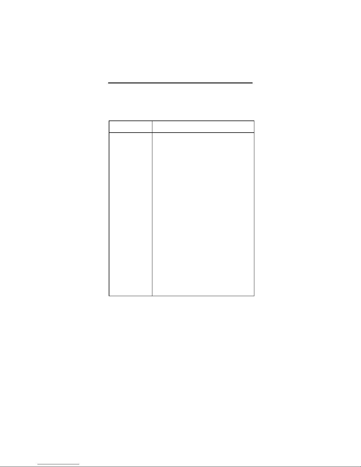
• Ensure that the TView MIcro is connected to
Chapter 5
Troubleshooting
This chapter describes possible problems that you might
encounter and ways to solve them.
Problem Possible Causes/Solutions
No video from
the TView
Micro
• Check the connection from the computer’s
video output port to the monitor in port at
the rear of the TView Micro unit.
• Check the connection from the comp video
out port or S-Video out port to the input on
your monitor or VCR.
• Ensure that the TV or VCR is ON.
• Check the connection from the power
supply. Is the TView unit plugged in to the
keyboard or USB port
• Ensure that your television or VCR has
been configured to accept auxiliary video
input.
the appropriate video connector on your TV
or VCR. At the TV or VCR end, the cable
should be connected to the VIDEO, VIDEO
IN, or AUX port.
Troubleshooting
30
Page 35
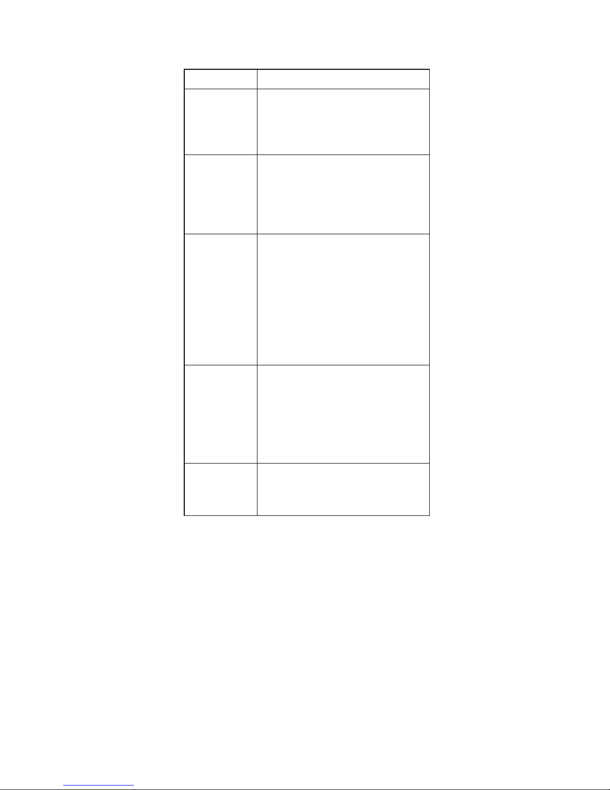
Picture Rolls • Ensure that your secondary monitor and
computer monitor size are supported by the
TView Micro
Flicker, or
other
Distortion on
your screen
Colors are
poor quality
or nonexistent
TV image
overshoots or
fails to fill the
screen
• Use of a RF modulator may cause image
quality problems. If at all possible, avoid
those devices that convert the TView Micro
signal into an antenna signal.
• Adjust the color and contrast controls on
your TV.
• Adjust the Video settings of the TView Micro
• Use of a RF modulator may cause image
quality problems. If at all possible, avoid
those devices that convert the TView Micro
signal into an antenna signal.
• Use the TView Micro’s horizontal and
vertical controls to adjust positioning.
• Adjust the Micro’s horizontal and vertical
sizing control to the appropriate setting.
• Adjust the vertical and horizontal size
controls on your TV.
Power
Concerns
• Check power connections.
• Possible power supply or TVIew Micro
failure.
Troubleshooting
31
Page 36

TView Micro User’s Guide
TView Micro
Failure
• Inspect the TView Micro unit for signs of
damage (i.e. broken pins, severed wires,
etc.).
Returning a Damaged or Failed
TView Micro Unit
To return a TView Micro unit, follow these
steps:
1. Contact FOCUS Enhancements Technical Support at
1-408-370-9963. A representative is available from
8:00 AM to 12:00PM & 1:00PM to 5:00PM Pacific
Standard Time (PST). Explain the nature of the
problem and any evidence of damage you may have
found. The customer representative will either assist
you with the specific problem or give you a Return
Materials Authorization Number.
Note: No goods will be accepted for warranty repair
or return without an RMA number that is written
on the outside of the package.
2. Pack the TView Micro carefully. If possible, use the
original shipping package. Send the package prepaid and insured via United Parcel Service (UPS) or
US Mail to:
Troubleshooting
32
Page 37

FOCUS Enhancements
ATTN: RMA# (Your RMA Number)
1370 Dell Avenue
Campbell, CA 95008
FOCUS Enhancements will repair or replace your TView
Micro within 5-15 working days. For units not covered
under the 1-year warranty, or where the warranty has
been voided, we charge a minimum fee of $90.00.
Troubleshooting
33
Page 38

Page 39

Page 40

Page 41

 Loading...