

Page 1
PICTOFOCUS
_____
BALANCED FLUE APPLIANCES
Installation, servicing and user instructions
Page 2

Contents
IMPORTANT
The flue system of this stove should only be installed and serviced by a
qualified engineer (i.e. Corgi registered engineer).
These instructions should be left with the customer for future reference.
This Manual Covers the following appliances :
· Pictofocus 1200
· Pictofocus 860
General section
IMPORTANT SAFETY NOTICE
GENERAL FITTING INFORMATION
User instructions
USING THE APPLIANCE
FIRST TIME OF OPERATION
OPERATING INSTRUCTIONS
A. GENERAL NOTES
B. SETTING THE ELECTRONIC CODE (first time use only)
C. SETTING FAHRENHEIT OR CELSIUS
D. SETTING THE TIME
E. CHILD PROOF
F. MANUAL MODE (handset)
G. DESIGNATED LOW FIRE AND HIGH FIRE
H. COUNTDOWN TIMER
I. MODES OF OPERATION
J. THERMOSTATIC MODE
K. PROGRAM MODE
L. AUXILIARY FEATURE
M. ECO MODE
MANUAL TURN OFF
03
03
03
04
04
04
04
09
Servicing instructions
TROUBLESHOOTING
Technical informations
APPLIANCE DIMENSIONS
PICTOFOCUS 860
PICTOFOCUS 1200
TECHNICAL INFORMATIONS
Appendix
15
15
16
16
17
18
Installer section
INSTALLATION
A. VENTILATION
B. GENERAL BALANCED FLUE NOTES
C. TERMINAL LOCATIONS WALL MOUNTING
D. TERMINAL ROOF LOCATIONS
INSTALLATION OF THE STOVE
A. STOVE LOCATION
B. GAS CONNECTION
C. PRESSURE TESTING
D. FLOOR PROTECTION (HEARTH)
ARRANGING THE CERAMIC FIRE-BED
A. LOG ARRANGEMENTS - EMBERS
B. LOG ARRANGEMENTS - NATURAL GAS
C. LOG ARRANGEMENTS - LPG GAS
D. PEBBLE ARRANGEMENTS
E. PEBBLE ARRANGEMENTS - NATURAL GAS
F. PEBBLE ARRANGEMENTS - LPG GAS
10
10
12
13
02
Page 3

General section
IMPORTANT SAFETY NOTICE
This appliance has a ceramic Fire-bed arrangement; this contains
Refractory Ceramic Fibres, which are man-made vitreous silicate fibres.
Excessive expo-sure to these materials can cause irritation to eyes,
skin and respiratory organs. Hence we recommend that when handling
these materials the release of dust should be kept to a minimum. During
installation and servicing we recommend that a HEPA filtered vacuum be
used to remove any dust and soot in and around the fire. If any of the
ceramic firme components need to be replaced we recommend that the
removed parts be sealed in a heavy-duty polythene bag, and be labelled
as RCF waste. RCF is not “Hazardous waste” and can be disposed of at a
licensed tipping site for the disposal of industrial waste.
The appliance incorporates an Oxygen Depletion Monitoring system.
(permanent pilot) This is located on the front of the burner, and must not
be adjusted by the installer. This system must not be put out of operation,
and if any parts require changing, only original manufacturer parts shall
be used.
This appliance is designed to be used either Natural or LPG gas however,
each individual appliance is only capable of running off the type of gas
spécifie at the time of purchase. It is important to note that once a type
of gas has been specified the stove cannot run off any other type. The
type of gas that your stove is capable of burning is stated on the data
information panel.
This appliance has been designed, tested and approved to meet standards
in place for product use, performance and safety. Installation of your Stove
must comply with current building regulations. It is therefore recommend
that a CORGI engineer be employed for this task. Taking particular notice
of “thermal inversion” The engineer will provide you with information about
the safety limits of the installation and should fix a notice plate in a place
where it can be readily seen.
This appliance must be installed in accordance with the rules in force and
used only in a sufficiently ventilated space, and is intended for use on a
gas installation with a governed meter.
Before installation, check that this appliance is compatible with local
distribution conditions, nature of gas and pressure. The technical
specification of this appliance is given on the rear page of this manual.
This appliance should not be used if the Glass is broken, and should
never be used with the Door open.
GENERAL FITTING INFORMATION
· Inlet pipe connection 8mm compression
· Chimney requirements Balanced Flue
· Flue monitor Permanent Pilot
· NO x level Class 1 (Nat. Gas), Class 5 (LPG)
User control: Variable rotary control inc. Integrated Piezo ignition, Permanent
pilot facility, Flame failure device and Oxygen Depletion Cut-out.
Before installation of these appliances, the area into which the fire is
to be fitted must be cleared of all debris (including dust), in particular
combustible material.
· Battery type (Remote Versions only)
· Receiver: 4 x 1,5V “AA”, R6 size.
· Transmitter: 2 x 1,5V “AAA” (Alkaline only).
This appliance is designed as an efficient heating device and consequently
all body parts become very hot in use. Except for the control knob and
control access door, which are designed to stay cool, all other parts are
working surfaces and should not be touched.
The glass and frame on this appliance acts as a fireguard conforming to BS:
1945 – 1971 and satisfies the Heating Appliance (Fireguards) régulations
1991. No part of the window or frame should be permanently removed.
IT DOES NOT GIVE FULL PROTECTION FOR YOUNG CHILDREN OR
THE INFIRM, extra protection should be considered for these conditions
conforming to BS 6539 or BS 6778.
Bearing in mind that the heat given off by this appliance may affect
articles placed close to it, curtains should not be placed within 30cm. The
appliance is not designed as a dryer. It is not therefore recommended that
the appliance be used in such a manner. Do not place any articles within
30cm of this appliance as this may result in damage to the articles.
The installation must be carried out in accordance with the following
regulations: The Building Regulations issued by the Department of
the Environment, the Building Standards (Scotland) (Consolidation)
Regulations issued by the Scottish Development Department. BS 1251,
BS 5440 part 1, BS 5871 part 2, BS 6461 part 1, BS 6891 and BS 8303.
In the Republic of Ireland the installation must be also conform to the
relevant standards, particularly in regard to flue sizing and ventilation.
Refer to documents IS813, ICP3, IS327 and any other rules in force.
03
Page 4

User instructions
USING THE APPLIANCE
VERY IMPORTANT
Read these instructions thoroughly before lighting.
This appliance will produce an odour and/or smoke for the first few hours
of use when new. Please ventilate the room when first lighting from new.
There is a flue spillage monitoring system fitted to this appliance, which
cuts off the gas supply upon the detection of spilled flue gasses. If this
system activates and the appliance cuts out, allow 3 minutes before
retrying the ignition, noting that the control tap must first be returned to the
off position. If the pilot will not light, allow a further 3 minutes or sufficient
time for switch to reset. If cutting off persists, then a professionally qualified
(i.e. CORGI registered) engineer should be informed.
The controls are located behind the access panel, which is the swing out
panel underneath the main door. The standard control is a basic rotary
tap, which has a single control knob. As an optional extra a remote control
version is available which has two rotary control knobs. The remote control
version must be specified at time of ordering.
All versions of this appliance operate with a traditional pilot light. The pilot
light is located in the centre of the burner, and is visible through the front
window. If the Flame Supervision Device Actuating Flame (the Pilot Light)
is extinguished either by intention or not, no attempt should be made to
relight until 3 minutes have elapsed.
IMPORTANT
Immediately after lighting, the appliance must be left on HIGH for ten
minutes in order to warm up the chimney.
WARNING
· Without using a mains adapter, battery replacement is recommended
at the beginning of each heating season.
· Old or dead batteries should be removed immediately. If left in the unit
the batteries can overheat, leak, and / or explode.
· Do NOT expose batteries (including during storage) to direct
sunlight, excessive heat, fire, moisture, or severe impact. Each of these
conditions can cause the batteries to overheat, leak, and / or explode.
· Batteries must be kept within their recommended temperature limits.
(Ambient battery temperature range: 32 °F to 131 °F [0 °C to 55 °C].)
· New and old batteries and different brands of batteries should not be
used together. Mixing of various batteries can cause the batteries
to overheat, leak, and / or explode.
Software Version
and buttons simultaneously. Software version is displayed.
Press
Handset Model Number
Press and buttons simultaneously. Handset model number
is displayed.
Deactivate Functions
1. Install batteries. All icons are displayed and flashing.
2. While the icons are flashing, press the relevant function button and hold
for 10 sec.
3. The function icon will flash until deactivation is complete. Deactivation
is complete when the function icon and two horizontal bars are displayed.
NOTE: If a deactivated button is pressed, there is no function, and two
horizontal bars are displayed.
NOTE: Deactivation remains in effect after change of batteries.
FIRST TIME OF OPERATION
Before igniting the appliance, ensure that all packaging, safety stickers
and any protective wrapping have been removed, and that the glass has
been cleaned, including all fingerprints from the glass.
Ensure that the room is adequately ventilated the first time that the
appliance is ignited; we would recommend opening windows if possible.
Run the appliance at full setting for a few hours so that the paint gets an
opportunity to fully cure. During this period it is possible for some fumes
and vapours to be given off. We would recommend keeping children and
pets out of the area at this time.
OPERATING INSTRUCTIONS
A. GENERAL NOTES
NOTICE
Wiring of valve and receiver must be completed before starting ignition.
Failure to do so could damage the electronics.
Batteries – Handset
· Low battery indicator on handsets.
Batteries – Receiver
· Low battery indication: frequent beeps for 3 seconds when motor turns.
· An AC mains adapter may be used instead of batteries.
· The module for fan speed control and light/dimmer includes mains
power together with batteries in the receiver for automatic backup in
case of power outage.
Activate Functions
1. Install batteries. All icons are displayed and flashing.
2. To activate a function, press the relevant button and hold for 10 sec.
3. The function icon will continue to flash until activation is complete.
Activation is complete when the function icon is displayed.
The following Functions can be Deactivated / Activated
· CHILD PROOF
· PROGRAM MODE
· THERMOSTATIC MODE (also deactivates PROGRAM MODE)
· ECO MODE
· LIGHT / DIMMER OPERATION
· CIRCULATING FAN OPERATION
· AUXILIARY FEATURE
· COUNTDOWN TIMER
B. SETTING THE ELECTRONIC CODE (First time use only)
Radio Frequency Handset
A code is selected automatically for all Mertik Maxitrol electronics from
among 65,000 codes available. The receiver must be paired with the
handset.
The receiver has to learn the handset code:
Press and hold the receiver’s reset button until you hear two (2) beeps. After
the second, longer beep, release the reset button. Within the subsequent
20 seconds press the button on the handset until you hear two (2) short
beeps confirming the code is set.
NOTE: This is a one time setting only, and it is not required when changing
the batteries In the handset or receiver.
04
Page 5
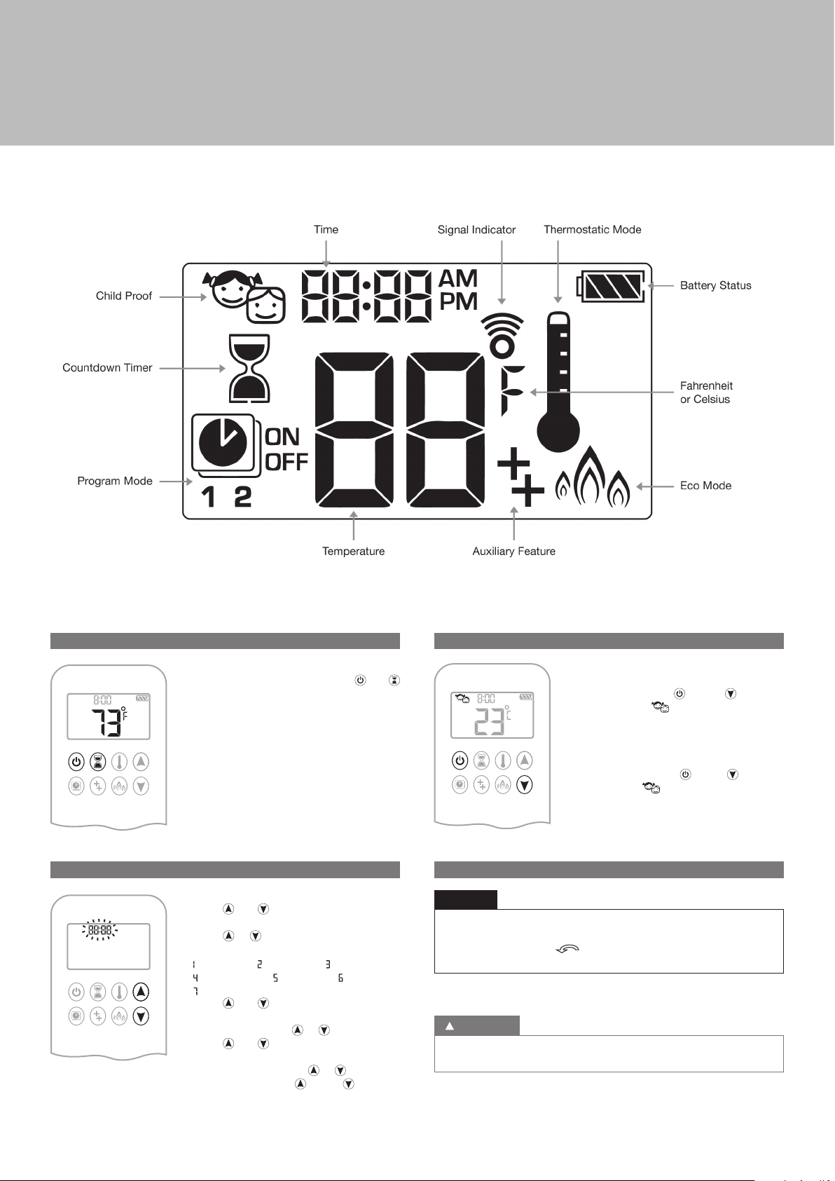
User instructions
Figure 01: 8-symbol Display
C. SETTING FAHRENHEIT OR CELSIUS
To change between °C and °F, press and
buttons simultaneously.
NOTE: Choosing °F results in a 12 hour clock.
Choosing °C results in a 24 hour clock.
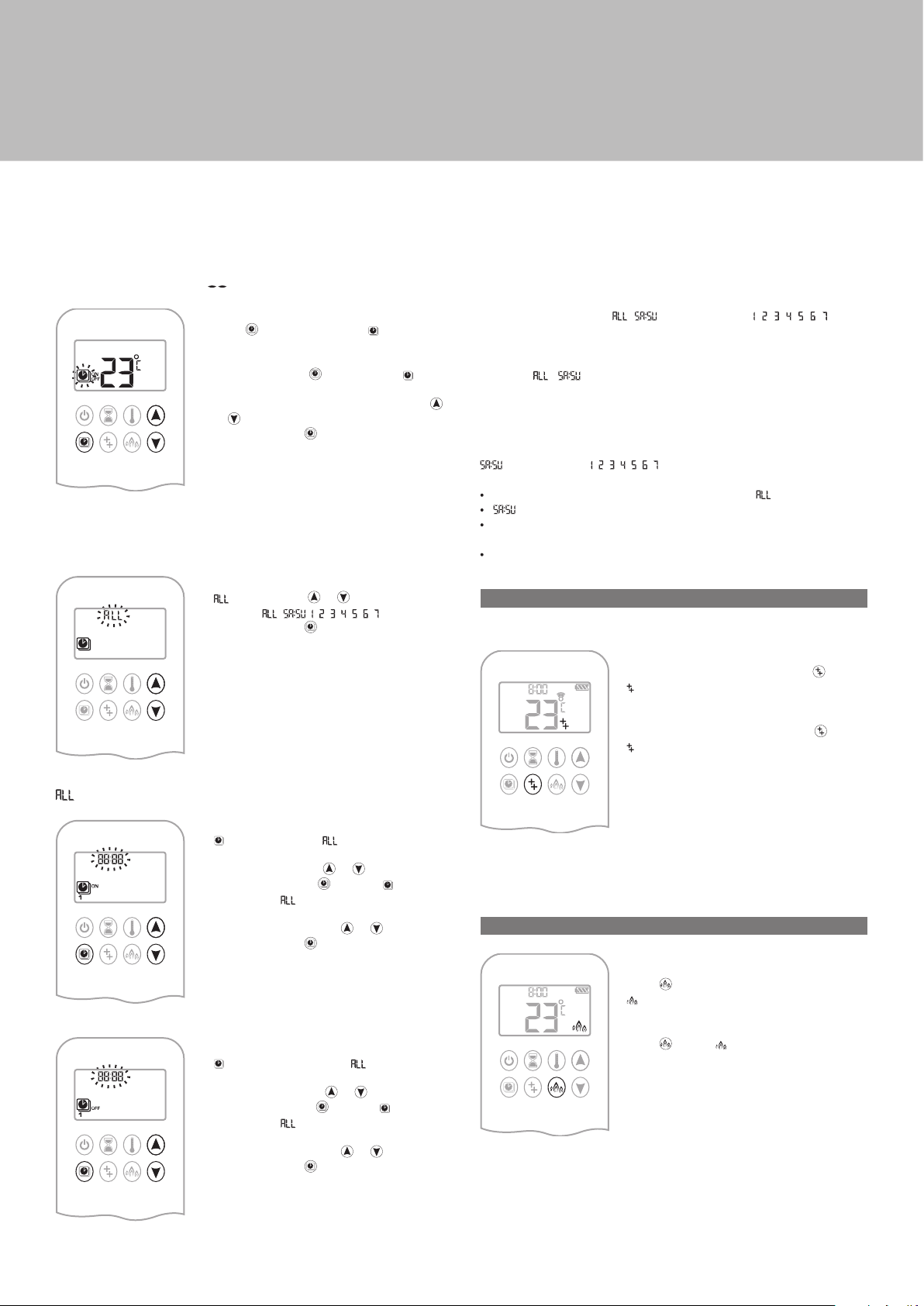
D. SETTING THE TIME
1. Press and buttons simultaneously.
Day flashes.
2. Press or button to select a number to
correspond with the day of the week (e. g.
= Monday, = Tuesday, = Wednesday,
= Thursday, = Friday, = Saturday,
= Sunday).
3. Press and buttons simultaneously.
Hour flashes.
4. To select hour press or button.
5. Press and buttons simultaneously.
Minutes flash.
6. To select minutes press or button.
7. To confirm press and buttons
simultaneously or wait.
E. CHILD PROOF
ON:
To activate press and buttons
simultaneously. displayed and the
handset is rendered inoperable, except for the
off function.
OFF:
To deactivate press and buttons
simultaneously. disappears.
F. MANUAL MODE (handset)
NOTICE
BEFORE OPERATING
1 Make sure MANUAL knob on the GV60 valve is in the ON,
full counterclockwise
2. Place the ON/OFF switch (if equipped) in the I (ON) position.
TO TURN ON FIRE
WARNING
When pilot ignition is confirmed, motor turns automatically to maximum
flame height.
position.
05
Page 6
User instructions
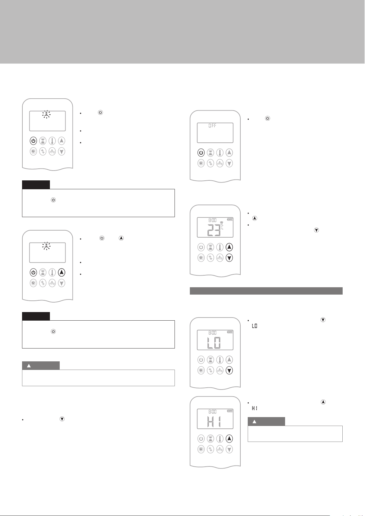
Handset One-Button Operation
(Default Setting)
· Press button until two short beeps and
a blinking series of lines confirms the start
sequence has begun; release button.
· Main gas flows once pilot ignition is
confirmed.
· Handset automatically goes into Manual
Mode after main burner ignition.
NOTICE
Change from one-button to two-button ignition operation by pressing
and holding
ON is displayed and 1 is flashing. When change is complete 1 will
change to 2.
button for 10 sec. immediately after installing batteries.
Handset Two-Button Operation
· Press and button simultaneously
until two short beeps and a blinking series
of lines confirms the start sequence has
begun; release buttons.
· Main gas flows once pilot ignition is
confirmed.
· Handset automatically goes into Manual
Mode after main burner ignition.
TO TURN OFF FIRE
Handset
· Press button to turn OFF.
NOTE: A new ignition is possible after the OFF
icon stops flashing.
FLAME HEIGHT ADJUSTMENT
Handset
· To increase flame height press and hold
button.
· To decrease flame height or to set appliance
to pilot flame, press and hold button.
NOTICE
Change from two-button to one-button ignition operation by pressing
and holding
ON is displayed and 2 is flashing. When change is complete 2 will
change to 1.
WARNING
If the pilot does not stay lit after several tries, turn the main valve knob
to OFF (p. XX).
STANDBY MODE (PILOT FLAME)
Handset
· Press and hold button to set appliance to pilot flame.
button for 10 sec. immediately after installing batteries.
G. DESIGNATED LOW FIRE AND HIGH FIRE
NOTE: Backlight must be on for high fire and low fire double-click
operation.
· To go to low fire, double-click button.
is displayed.
NOTE: Flame goes to high fire first before
going to low fire.
· To go to high fire, double-click button.
is displayed.
WARNING
If the appliance will not operate, turn the main
valve knob to OFF (p. XX).
06
Page 7
User instructions
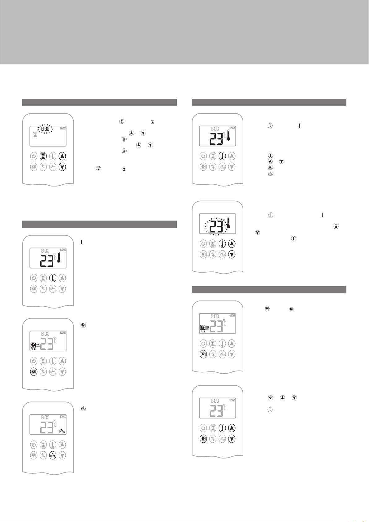
H. COUNTDOWN TIMER
ON/SETTING:
1. Press and hold button until displayed,
and hour flashes.
2. To select hour press or button.
3. To confirm press button. Minutes flash.
4. To select minutes press
5. To confirm press
OFF:
Press button, and countdown time
disappear.
NOTE: At end of countdown time period, the fire shuts off. The Countdown
Timer only works in Manual, Thermostatic, and Eco Modes.
Maximum countdown time is 9 hours and 50 minutes.
I. MODES OF OPERATION
Thermostatic Mode
The room temperature is measured and
compared to the set temperature. The flame
height is then automatically adjusted to
achieve the set temperature.
or button.
button or wait.
J. THERMOSTATIC MODE
ON:
Press button. displayed, preset
temperature displayed briefly, and then room
temperature displayed.
OFF:
1. Press button.
2. Press or button to enter Manual Mode.
3. Press
4. Press
SETTING:
1. Press button and hold until displayed,
temperature flashes.
2. To adjust set temperature press or
button.
3. To confirm press
button to enter Program Mode.
button to enter Eco Mode.
button or wait.
Program Mode
PROGRAMS 1 and 2, each can be
programmed to go on and off at specific times
at a set temperature.
Eco Mode
Flame height modulates between high
and low. If the room temperature is lower
than the set temperature, the flame height
stays on high for a longer period of time. If
the room temperature is higher than the set
temperature, the flame height stays on low
for a longer period of time. One cycle lasts
approx. 20 min.
K. PROGRAM MODE
ON:
Press
displayed.
OFF:
1. Press or or button to enter Manual
Mode.
2. Press
button. , 1 or 2 , ON or OFF
button to enter Thermostatic Mode.
NOTE: The set temperature for Thermostatic Mode is the temperature for
the on time in Program Mode. Changing the Thermostatic Mode set
temperature also changes the on time temperature in Program Mode.
07
Page 8
User instructions
Default settings:
ON TIME (Thermostatic) TEMPERATURE: 21 °C (70 °F)
OFF TIME TEMPERATURE: “
NOTE: The on (Thermostatic) and off set temperatures are the same for
each day.
” (pilot flame only)
TEMPERATURE SETTING:
1. Press button and hold until flashes. ON
and set temperature (setting in Thermostatic
Mode) displayed.
2. To continue press
displayed, temperature flashes.
3. Select off temperature by pressing the
button.
or
4. To confirm press
DAY SETTING:
flashes. Press or button to choose
5.
between
6. To confirm press button.
button or wait. , OFF
button.
, , , , , , , , .
NOTE: Either continue to PROGRAM 2 and set on and off times or stop
programming at this point, and PROGRAM 2 remains deactivated.
NOTE: PROGRAM 1 and 2 use the same on (Thermostatic) and off
temperatures for , and Daily Timer ( , , , , , , ). Once
a new on (Thermostatic) and / or off temperature has been set, that
temperature becomes the new default setting.
NOTE: If
and PROGRAM 2 on and off times, these become the new default
times. The batteries must be removed to clear the PROGRAM 1
and PROGRAM 2 on and off times and temperatures.
· Set on time and off time using same procedure as “ selected” (above).
· : Set on time and off time for both Saturday and Sunday.
· Daily Timer: Unique on and off times may be set for a single day of
the week, for multiple days of the week, or for every day of the week.
· Wait to finish setting.
L. AUXILIARY FEATURE
Upon ignition burner 1 is on and burner 2 is in the last setting.
, or Daily Timer are programmed for PROGRAM 1
or Daily Timer ( , , , , , , ) selected
ON:
To switch a burner ON, press the
displayed.
button.
selected
ON TIME SETTING (PROGRAM 1):
, 1, ON displayed, is displayed shortly,
7.
and hour flashes.
8. To select hour press
9. To confirm press button. , 1, ON
displayed, displayed shortly, and
minutes flash.
10. To select minutes press or button.
11. To confirm press button.
OFF TIME SETTING (PROGRAM 1):
, 1, OFF displayed, is displayed
12.
shortly, and hour flashes.
13. To select hour, press
14. To confirm press
displayed,
minutes flash.
15. To select minutes press or button.
16. To confirm press button.
or button.
or button.
button. , 1, OFF
displayed shortly, and
OFF:
To switch the burner OFF, press the button.
disappears.
NOTE: The latching solenoid valve cannot operate manually. If the receiver
battery runs down it will remain in the last operating position.
M. ECO MODE
ON:
Press
button to enter Eco Mode.
displayed.
OFF:
button. disappears.
Press
08
Page 9
User instructions
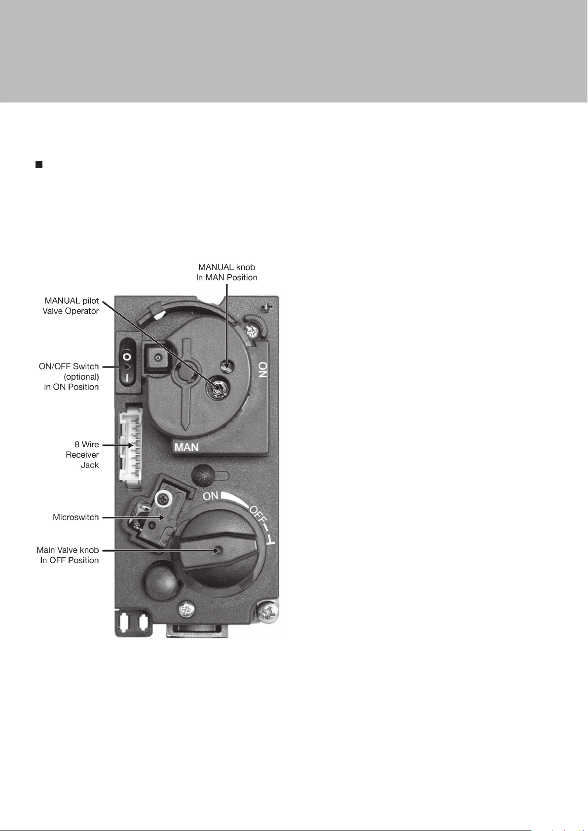
MANUAL TURN OFF
In the event that the appliance needs to be turned OFF manually,
for instance, if the remote control is lost or the batteries become totaly
flat, the control valve must be accessed and the switch flipped to OFF
(marked “0”).
The picture below shows the control valve.
09
Page 10

Installer section
INSTALLATION
Before beginning the installation, check that the details on the rating plate
correspond to the gas type and pressure to which the appliance will be
connected.
A. VENTILATION
Balanced Flue appliances can be installed into a house without the need
for additional ventilation. They can also be installed into a room that has a
forced mechanical ventilation and/or fume extraction without any special
extra requirements.
B. GENERAL BALANCED FLUE NOTES
IMPORTANT
The CE label has been obtained for a connection exclusively made with
Poujoulat and On Top flues.
There are many possibilities for installing this Concentric Balanced Flue
system into a building, both Roof and Wall terminations are possible, and
the flue can either be built into an existing chimney or a completely new
flue system may be constructed.
The system is based upon a Concentric Flue system which utilises an
inner flue of 100mm diameter which passes through an outer flue of
150mm diameter. The flue gasses that are the products of combustion of
the fire, pass through the inner flue and are safely vented to the outside
environment. The gap between the inner and outer flues is the channel by
which the stove is supplied with air for combustion.
These concentric flues terminate outside of the property in a terminal, this
terminal will keep the expelled gasses and the fresh air for combustion
seperate. It is important that the terminal is not blocked, a suitable guard
maybe required if the terminal is located at a “Low” level (usually when the
terminal is within 2m of floor level).
The Balanced Flue gas appliance can be installed as either a built in
appliance in a new fireplace, or be installed as an insert into an existing
open fireplace. If an existing Flue or Chimney is to be utilised, then the
installation engineer must be consulted. If the chimney has been previously
used it must be professionally cleaned and certified as being sound and
fit for use.
The European CE approval on this appliance is restricted to the Flue
systems as specified by the supplier, thus the appliance must only be
insalled with the original flue system, no others may be used.
The following few pages give brief details of terminal location. For further
information including flueing sugestion please refer to the accompaniing
booklet “Balanced Flue Fitting Solutions”.
10
Page 11
Installer section
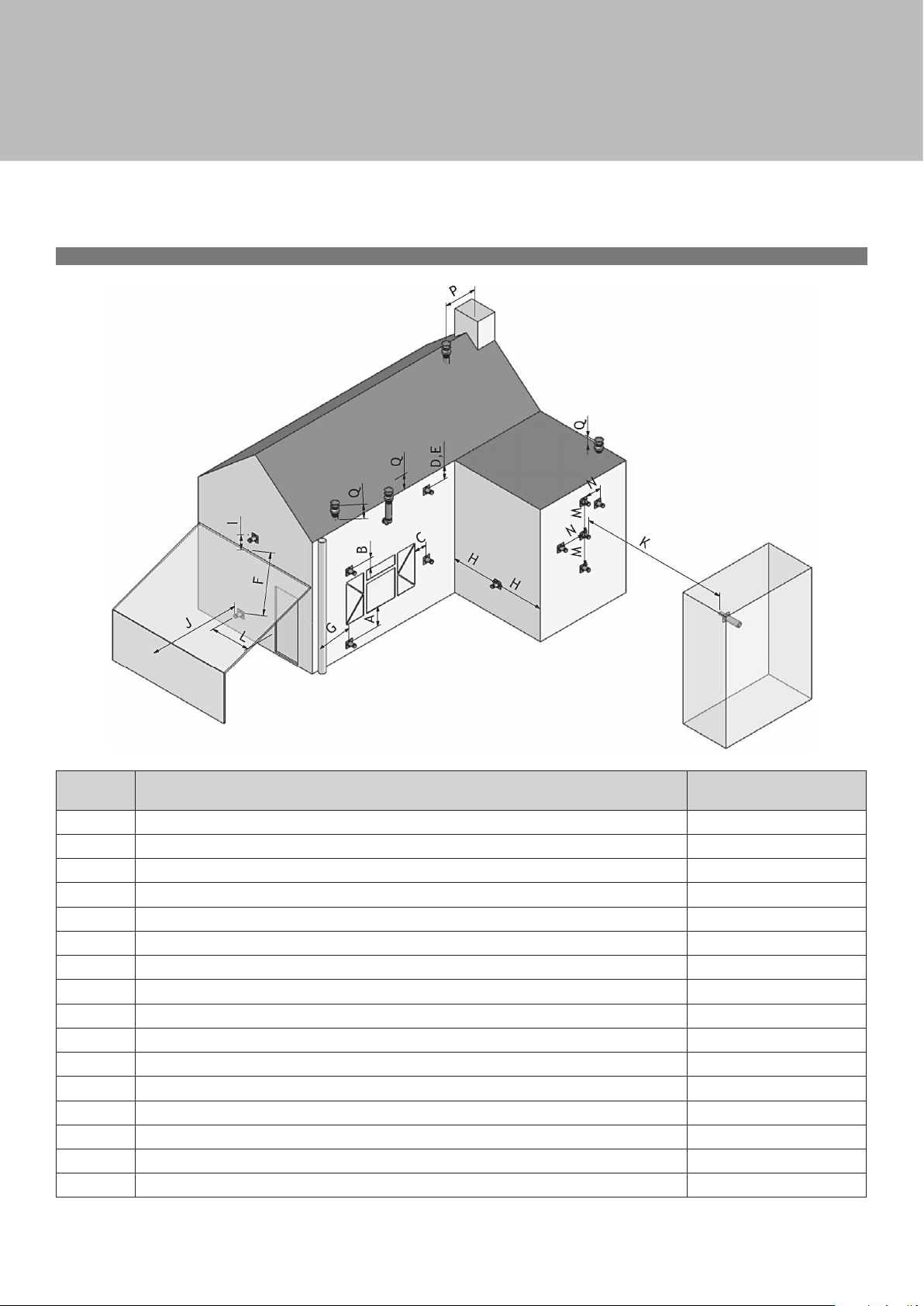
C. TERMINAL LOCATIONS WALL MOUNTING
Dimension Terminal Locations Distance (mm)
A* Directly below an opening, air brick, opening window, etc. 600
B Above an opening, air brick, opening window, etc. 300
C Adjacent to an opening, air brick, opening window, etc. 400
D Below gutters, soil pipes or drain pipes 300
E Below eaves 300
F Below balconies of car port roof 600
G From a vertical drain pipe or soil pipe 300
H From a internal or external corner 600
I Above ground roof or balcony level 300
J From a surface facing the terminal 600
K From a terminal facing the terminal 600
L From an opening in the car port (e.g. door, window into the dwelling). 1200
M Vertically from a terminal on the same wall 1500
N Horizontally from a terminal on the same wall 300
P From a vertical structure on the roof 600
Q Above intersection with roof 150
* I addition, the terminal should not be nearer than 300mm to an opening in the building fabric formed for the purpose of accomodating a built in element
such as a window frame.
11
Page 12

Installer section
D. TERMINAL ROOF LOCATIONS
“Distance” = minimum distance required for positioning of the outlet to
avoid adverse effects with respect to:
A. A ventilation opening serving an occupied room, a toilet or a bathroom.
B. A heating air supply, when the supply flows through an occupied room.
C. A window that can be opened and that is near an occupied room,
a toilet or a bathroom.
To avoid adverse effects Distance : outlet A, B, ou C
At the same roof level > 6 m (*)
At a diffeerent roof level > 3 m (*) (**)
At a lower positioned wall > 2 m (**)
At a higher sloping surface > 6 m (***)
(*) If the required distance cannot be achieved, the outlet position rules
take precedence.
(**) If the outlet is positioned at least 1 m higher than the intake supply
opening, or a window that can be opened.
(***) If the required distance cannot be achieved, the position of the outlet
must be at least 1 m above the highest facade/roof.
INSTALLATION OF THE STOVE
This appliance must be installed by a qualified (CORGI) gas engineer, and
must be installed in accordance with the Regulations and Standards listed
in the front of this Manual.
B. GAS CONNECTION
It is important to ensure that all pipe work installed is fitted in accordance
with BS6891 and is capable of supplying sufficient gas flow and pressure to
meet the minimum pressures Technical section of this manual. A minimum
pipe size of 15mm should be used for the gas supply to within 1 metre of
the appliance. 8mm pipe may only be used for the final connection to the
stove, or within 1 meter of the appliance. An 8mm nut and olive is supplied
with the stove for the final pipe joint.
A gas supply tap must be installed in the supply pipe work in a location that
is easily accessible, such that the appliance may be isolated if necessary.
Do not make any connections to the appliance until all supply pipes have
been purged to expel any dust or debris. Failure to do this may result in a
bloque injector or tap and will invalidate the guarantee.
Although a gas soundness test is made on all appliances before they leave
the factory, the appliance should be tested for soundness before operating
the stove. This is to ensure that the burner has not been damaged in transit.
C. PRESSURE TESTING
The gas pressure to the burner must be measured; this should be
measured with all gas appliances after the gas meter operating on full,
including this stove.
D. FLOOR PROTECTION (HEARTH)
These appliances are designed with the “Firebox” raised up off the ground
level by the built in “Base unit”.
Thus these appliances require no special Hearth arrangements, as the floor
will not get hot and is protected by the steel construction of the “Base unit”.
Failure to comply with the instructions in this manual, or the regulations
and standards will result in the Guarantee being void and could have
hazardous consequences.
A. STOVE LOCATION
These appliances are designed with the “Firebox” raised up off the ground
level by the built in “Base unit”.
Thus these appliances require no special Hearth arrangements, as
the floor will not get hot and is protected by the steel construction
of the “Base unit”.
· The appliance must not be fitted against a rear wall constructed from
a combustible material; a gap of 300mm should be given all round the
stove before combustible materials may be used in the wall construction.
· If the appliance has to be located in an opening, a minimum clearance
of 50mm should be alowed to non-combustible materials.
· The stove must be located at least 280mm from any combustible
materials.
· A combustible shelf may be fitted over the appliance, if in the case
of a 150mm or less deep shelf; there is at least 280mm clearance above
the top of the stove. The shelf depth may increase at the same rate
as the increase in clearance; i.e. a shelf depth of 200mm would require
a clearance of 330mm.
12
Page 13
Installer section
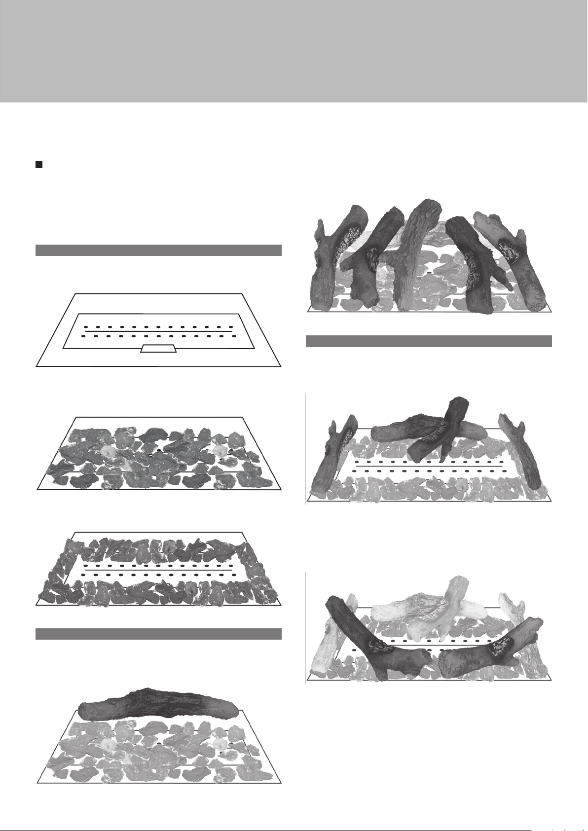
ARRANGING THE CERAMIC FIRE-BED
Only the ceramics supplied with this appliance are to be used. The
ceramics must be laid only as shown on the following pages. Replacement
parts including mat are available from your dealer, but should only be
installed by a qualified installation engineer.
A. LOG ARRANGEMENTS - EMBERS
Place the Mat on top of the burner such that all the holes on the mat align
with the holes on the burner top plate.
Scatter the Embers over the top of the Mat and the Grate. Special care
must be taken not to let any embers enter the Pilot Shield and impinge on
the pilot or thermocouple.
Place the remaining five logs as shown in the picture below, i.e. the logs
are placed so that one end of each log reaches to the front of the fire, and
the other end rests on top of the large log at the rear of the fire.
C. LOG ARRANGEMENTS - LPG GAS
Place the Large Log across the rear of the fire, as shown in the picture
below. This log should be placed such that it is only on top of the grate and
not sitting on top of the burner.
When arranging the embers for LPG (shown above) the Gas Ports on top
of the burner must be left clear.
B. LOG ARRANGEMENTS - NATURAL GAS
Place the Large Log across the rear of the fire, as shown in the picture
below. This log should be placed such that it is only on top of the grate and
not sitting on top of the burner.
Place one of the brached logs on the rear of the burner such that it stands
up against the rear log, as shown in the picture below.
Now select the two straight logs, and place them on the fuel bed so that
they are placed one at each end of the burner.
Place the two remaining logs symetrically at the front of the burner so that
they curve around from the pilot shield to rest on the logs at the end of the
burner. The central holes on top of the burner should remain unblocked
by the Logs.
13
Page 14
Installer section
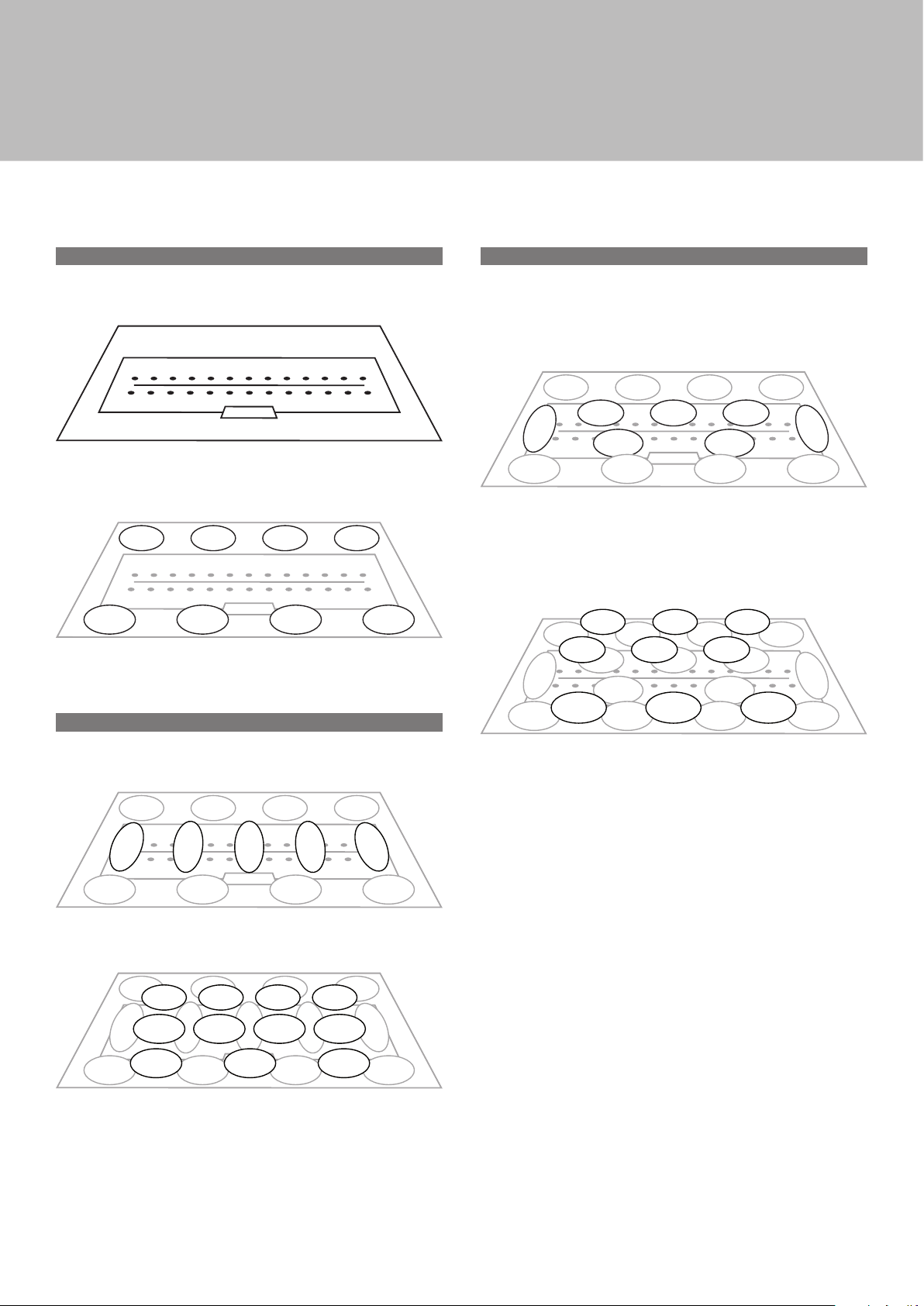
D. PEBBLE ARRANGEMENTS
Place the Mat on top of the burner such that all the holes on the mat align
with the holes on the burner top plate.
Take eight of the pebbles and place them on top of the firebed area, such
that there are four pebbles at the back of the fire and four pebbles at the
front of the fire, as shown in the picture below.
The remainder of the pebble layout is now dependent upon gas type., so
follow the proceedure for the gas type below.
F. PEBBLE ARRANGEMENTS - LPG GAS
Place two of the Pebbles, one at each end of the burner, against the firebox
(1-2). Position another two pebbles at the very front of the burner, one either
side of the pilot shield (3-4). Place three more pebble at the rear of the
burner, ensuring that the Gas Ports at the rear of the burner are not blocked
(5 to 7). The picture below shows show the pattern should now look.
Now place a row of three pebbles such that it is sitting on top of the front
pebbles, already in place (8 to 10). Repeat this process with another row
of three pebbles, this time sitting on top of the rear two rows of pebbles
already in place (11 to 13). Take the final three pebbles and lay them on
top of the very rear row and up against the back plate of the firebox (14
to 16). The layout is now complete and should look like the picture below.
E. PEBBLE ARRANGEMENTS - NATURAL GAS
Place five of the remaining pebbles down the centre of the burner, lying
from front to back, as shwon in the picture below.
Place the last eleven pebbles on top of the thirteen existing pebbles as
shown in the picture below.
14
Page 15

Servicing instructions
The following outlines only the minimum work that should be performed on
an annual basis. This service work, like any other work on the appliance,
must only be done by a qualified and competent engineer who is CORGI
registered.
· Open the door and remove all ceramics.
· Remove mat from top of burner.
· Remove any debris from the top of the burner using a vacuum cleaner
and brush.
· Inspect the burner unit.
· Perform an ignition check.
· Perform a flame failure check.
There should be no need to service the burner. If however this is required,
then the engineer should check the setting pressure at inlet to burner; the
correct pressure is shown at the rear of the manual. Brush off and replace
ceramic arrangement as earlier in this manual, replacing any broken or
damaged pieces.
· Check all seal on door (including glass) and replace the Door.
· Check the installation for gas leaks.
· Check flue for clearance of products of combustion.
If any parts need to be replaced use only genuine parts, non-standard
parts will invalidate the guarantee and may be dangerous.
TROUBLESHOOTING
THE GAS PILOT WILL NOT IGNITE OR STAY LIT ?
· Ensure the gas is turned on at the appliance and the meter/cylinder.
· Depress the control knob (•) for at least twenty seconds once
the pilot is alight to ensure the operation of the safety
thermocouple valve.
· Ensure that the pilot injector is not obstructed or blocked and it
is free from any dust or dirt.
· Ensure that the thermocouple has not been damaged in transit.
This is a very delicate Electro-magnétique device.
· On propane, the cylinder could be empty.
THE PILOT IS NOT BURNING OR PERFORMING CORRECTLY ?
· Ensure the pilot flame is the correct size for the type of gas.
The flame should be focused on the thermocouple probe.
· The pilot flame will have been set correctly in the factory.
THE MAIN BURNER DOES NOT SEEM TO BE BURNING CORRECTLY ?
· Ensure adequate gas pressure to the appliance. Test pressure
by releasing the pressure test screw and applying a manometer.
· Ensure adequate volume of gas is being used. Once the fire
is burning on maximum, turn off all other gas appliances in
the house and calculate the fuel being burned from the gas meter.
· Make sure that the burner is burning correctly. The flame should
be even across the top of the burner before any coals are placed
on top.
15
Page 16
Technical informations
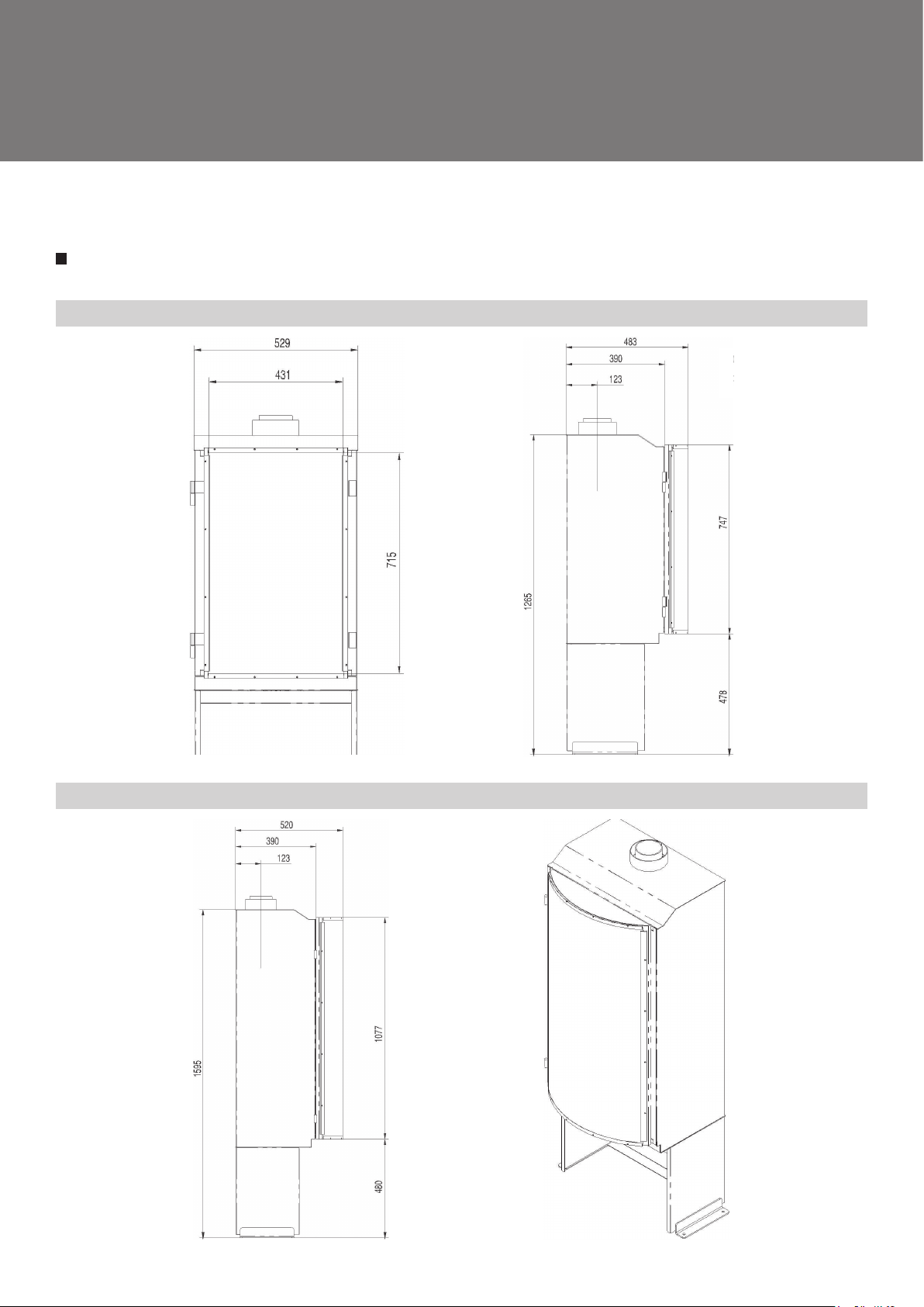
APPLIANCE DIMENSIONS
PICTOFOCUS 860
PICTOFOCUS 1200
16
Page 17
Technical informations
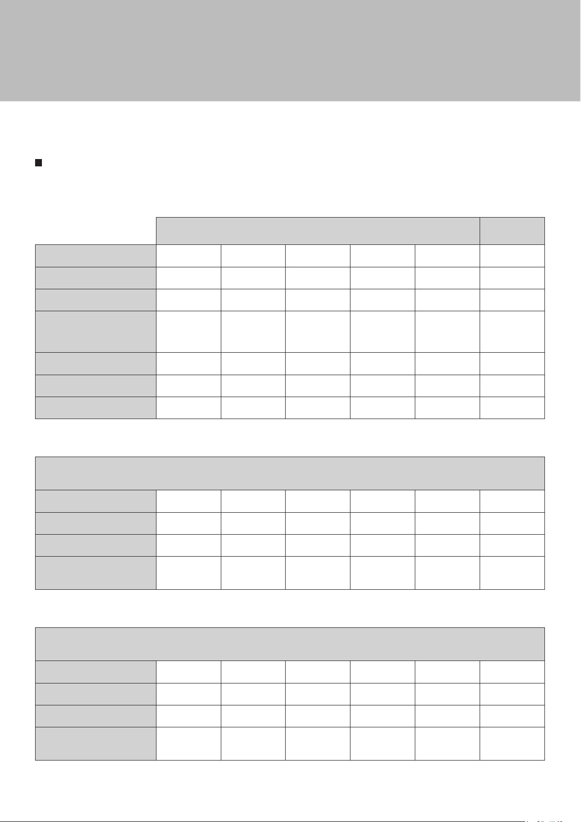
TECHNICAL INFORMATIONS
Product Identification Number: 0359CR997
Gas Category I2H I2E I2E+ I2ELL I2L I3P
Gas G20 G20 G20/G25 G25 G25 G31
Supply Pressure (mbar) 20 20 20/25 20 25 30
Countries of Destination
Efficiency Class 2 2 2 2 2 2
Nox Class 1 1 1 1 1 5
Pilot Burner (SIT OP) 0.977.113 0.977.113 0.977.113 0.977.113 0.977.113 0.977.148
AT, DK, ES, FI,
GB, GR, IE, IT,
PT, SE
DE, LU BE, FR DE NL
Natural Propane
ES, FR, GB, GR,
IE, IT, PT
Pictofocus 860
Nominal Input (Gross kW) 10,5 10,5 10,5 / 10 8,8 10 9
Gas Rate (max. m3/hr) 1,073 1,073 1,073/1,117 1,073 1,117 0,312
Burner Pressure (Hot mbar) 10,9 10,9 10,9 / 13 10,9 13 28,9
Burner Injector (Bray)
1200
7 x ø 1,2mm
1200
7 x ø 1,2mm
1200
7 x ø 1,2mm
1200
7 x ø 1,2mm
1200
7 x ø 1,2mm
280
7 x ø 0,3mm
Pictofocus 1200
Nominal Input (Gross kW) 10,5 10,5 10,5 / 10 8,8 10 9
Gas Rate (max. m3/hr) 1,073 1,073 1,073/1,117 1,073 1,117 0,312
Burner Pressure (Hot mbar) 10,9 10,9 10,9 / 13 10,9 13 28,9
Burner Injector (Bray)
1200
7 x ø 1,2mm
1200
7 x ø 1,2mm
1200
7 x ø 1,2mm
1200
7 x ø 1,2mm
1200
7 x ø 1,2mm
280
7 x ø 0,3mm
17
Page 18
Appendix
DECLARATION
ATELIER DOMINIQUE IMBERT s.a.s.
3 Impasse Claque Patin
F - 34380 Viols le Fort
declares that the FOCUS independent gas fired convection heaters described here
are in accordance with the appliances described in the EC-Type Examination
Certificate No. UK-LHD-0359-0657R1 delivered by INTERTEK and comply with the
essential requirements applicable to EN 613 :2001 + A1 :2008 and Regulation UE
2016/426.
Signed for and behalf of the manufacturer by :
OF CONFORMITY
Laurent Gaborit
Directeur Général
Viols le Fort, le 14 octobre 2016
18
Page 19

Note
19
Page 20

Création - Édition - Distribution :
Atelier dominique imbert
S.A.S. au capital de 102 355 euros
34380 Viols-le-Fort
France
Tel. : 00 33 (0)4 67 55 01 93
Fax. : 00 33 (0)4 67 55 77 77
Web : www.focus-creation.com
Email : [email protected]
V. 01 - July 2017
 Loading...