

Page 1
Page 2

DISCLAIMER
Television screens are simulated and subject to change without
notice. This device is not to be used for the unauthorized copying of
copyrighted material.
TRADEMARKS
MX-4 DV, the FOCUS Enhancements logo, and MX-4 DV are
trademarks or registered trademarks of FOCUS Enhancements Hi8
and i.LINK are trademarks of Sony Corporation. FireWire is a registered trademark of Apple Computer. VHS is a registered trademark of JVC. Other product and brand names might be trademarks
or registered trademarks of their respective companies and are
hereby acknowledged.
FOCUS Enhancements MX-4 DV User Guide, © 2004. No part of
this book may be reproduced in hard copy, electronically, or by any
other means without the expressed, written permission of FOCUS
Enhancements
FCC Statement
This equipment has been tested and found to comply with the limits
for a Class A digital device, pursuant to part 15 of the FCC Rules.
These limits are designed to provide reasonable protection against
harmful interference when the equipment is operated in a commercial environment. This equipment generates, uses, and can radiate
radio frequency energy and, if not installed and used in accordance
with the instruction manual, might cause harmful interference to
radio communications. Operation of this equipment in a residential
area is likely to cause harmful interference, in which case the user
must correct the interference at his/her own expense.
MANL-0956-01
Page 3

CONTENTS
DISCLAIMER • 2
TRADEMARKS • 2
FCC Statement • 2
1INTRODUCTION
Major Features • 2
Common Uses for MX-4 DV • 4
MX-4 DV Package Contents • 5
About this User Guide • 6
2QUICK START
Quick Start Steps • 10
Setting Up • 10
The Preview Screen • 11
Running the Demo • 12
Cutting Between Sources • 13
Borders and Solid Color Backgrounds • 13
Setting up a Transition • 13
Running Transitions • 14
Using CUT Transitions • 14
Choosing Transitions • 15
Using Transition Categories • 15
Other Features • 15
3INSTALLING THE MX-4 DV
Sources and Output • 18
Preview and Program Monitors • 18
Preview Monitor • 19
Program Monitor • 19
Number of Monitors • 19
Understanding MX-4 DV Connectors • 20
Power Connector • 22
Cables and Adapters • 22
Installation Examples • 24
Correlating Input Sources to MX-4 DV Jacks • 24
Using Headphones • 25
VCR Selector Switches • 25
General Notes • 25
Post Production Configuration • 26
Live Broadcast Configuration • 28
Using a Microphone with MX-4 DV • 30
4BASIC OPERATIONS
Starting and Stopping the MX-4 DV • 32
Understanding the Keyboard • 32
Using the Preview Screen • 35
Changing the Display Configuration • 35
Input Source Previews • 36
Active Source Highlights • 36
Color Selector • 37
Transitions Menu • 37
Selected Transition • 37
Using CURRENT and NEXT Sources • 38
Selecting Sources • 39
Using the Video/Audio Selector • 39
Swapping Sources • 40
Simple Cuts • 40
Swapping Between Two Sources • 40
Working with Colors • 41
Identifying Colors • 42
Using Color Backgrounds • 42
Changing Colors and Styles • 42
Creating Custom Colors • 43
Using Borders • 43
Changing Border Styles • 44
5TRANSITIONS
Basic Transition Concepts • 48
Transition Categories and Menus • 50
Basic Transitions Category • 51
Edges Transitions Category • 51
Misc. Transitions Category • 51
Shapes Transitions Category • 51
User Transitions Category • 51
Changing User Transitions Menu • 52
Selecting Transition Sources • 53
Setting the CURRENT Source • 53
Setting the NEXT Source • 53
Selecting Transitions • 54
Using the Transitions Menu • 54
Using Transition Numbers • 55
Adjusting Transitions • 56
Changing Transition Speed • 56
Changing Transition Direction • 56
Running Transitions • 58
Running Transitions Automatically • 58
Running Transitions Manually • 58
6INPUT EFFECTS
Input Effects Menu • 60
Special Key Combinations • 61
Using Input Effects • 62
B&W • 63
B&W Neg • 63
Posterize • 63
Flip Horizontal • 63
Mosaic • 64
Color Correct • 64
Color Neg • 64
Video Adjustment • 65
Chromakey • 65
Flip Vertical • 65
Strobe • 65
7FUNCTIONS
Demo • 68
Running a Locked Demo • 68
Display • 69
Setup • 71
Force Field Freeze • 72
GPI Out Mode • 72
Comb Filter • 72
Audio Mode • 72
Dual Monitor Mode • 72
7.5 IRE Pedestal • 72
FTP • 73
Route • 73
Configuring the MX-4 DV • 73
Page 4

CONTENTS
Changing the Routing • 74
Example: Changing the Routing • 75
Routing Audio Through Color or Background Channels • 76
Sub-Route Menus • 77
Learn • 78
Compose • 79
PIPs • 79
Audio Mix • 79
Freeze • 79
Field and Frame Freezes • 79
Major Freeze Functions • 80
Freeze Examples • 80
8PIPS
Single PIP • 84
Background Tile • 84
Foreground Tile • 84
Using Other Effects with Single PIPs • 86
Multi-PIP • 87
Using Freeze Effect with Multi-PIPs • 88
9COMPOSE
Basic Composition Steps • 90
Backgrounds • 90
Foreground Tiles • 91
Creating Color Tiles and Lines • 91
Creating Moving Video Tiles • 91
Creating Still Image Tiles • 91
Manipulating Tiles • 91
Positioning Tiles • 91
Sizing Tiles • 92
Composition Rules • 92
Creating a Composed Image • 93
Playing the Composition • 94
Exiting from Compose Mode • 94
10 CHROMAKEY
Preparing the Background Footage • 96
Preparing the Keyed Footage • 97
Preparing the Chromakey Footage • 97
Performing the Chroma key • 99
Fine-Tuning Key Colors • 99
Ending Chroma Key • 99
11 LEARN MODE
Learned Environments • 102
Learned Scripts • 103
Using Learn Mode • 104
Other Useful Information • 105
Aborting a Playback Session • 105
12 WORKING WITH AUDIO
Audio Devices You Can Use • 108
Ways You Can Control Audio • 108
Controlling Audio Transitions • 108
VIDEO/AUDIO Selector • 108
Selecting Audio Sources • 109
Ways to Use Audio • 109
Audio Accompanies Video • 109
Continuous Audio • 110
Using the Audio Mixer • 111
Audio Mixer Controls • 112
Using Background Audio • 112
Using Headphones • 113
Advanced Audio Steps • 113
Using the Analog Audio Adjustments Function • 113
Selecting Manual Levels • 114
Selecting Audio Delay • 114
13 ADVANCED OPERATIONS
Using Titles • 116
Using Color Bars • 116
Performing Roll Edits • 117
Cutting Between Scenes • 117
A/A Roll Edits • 117
A/B Roll Edits • 118
Transitions TO and FROM Solid Colors • 118
Transitions to Modified Sources • 119
Operating in Live Environments • 119
Security Monitoring • 119
Using a GPI Device • 120
Instructions for Building a GPI Trigger • 121
Using a GPI Trigger Device • 122
Resetting the MX-4 DV Factory Defaults • 122
Connecting with Ethernet • 123
IP Setup for a Computer or Laptop • 124
Transferring Files TO or FROM the MX-4 DV • 130
Updating System Software • 131
Information About FTP Clients • 132
ATRANSITIONS LIST 135
Basic Transitions • 136
Edge Transitions • 144
Misc. Transitions • 145
Shape Transitions • 146
Default User Transitions • 151
BTIME BASE CORRECTOR 153
Dual TBC Mode • 153
Vertical Interval Data • 153
TBC Technical Information • 154
CVIDEO QUALITY 155
Preview Image Quality • 155
Video Scaling Artifacts • 156
Freeze Quality • 156
Video Processing Artifacts • 156
DTECHNICAL SPECIFICATIONS 157
ELP FOR MXPRO DV USERS 159
EH
MX-4 DV Defaults to Y/C on All 4-Channels • 159
Transitions Organized Differently • 159
Glossary
Index
Page 5

CHAPTER 1
INTRODUCTION
Welcome to the MX-4 DV, and thank you for buying FOCUS Enhancements products.
This chapter contains:
• Brief descriptions of major MX-4 DV features
• Typical uses for the MX-4 DV
• How to contact FOCUS Enhancements
• An inventory of package contents
• Description of the contents of this User Guide
Please take a few moments to read the material so you can take full advantage of all
MX-4 DV benefits.
Page 6
2
MX-4 DV USER GUIDE CHAPTER 1
MAJOR FEATURES
MX-4 DV contains features found on most video mixers. In addition, it contains the special features described in this section.
Superb Video Quality — To ensure the highest video quality, the MX-4 DV uses 10-bit (4:2:2)
video technology for Y/C applications, and 8-bit 4:2:2 for composite applications.
Four Input Synchronized Switcher — MX-4 DV provides four input channels that mix analog
sources. This makes MX-4 DV useful in live production settings where up to four cameras or other
sources might be in use. MX-4 DV synchronizes the inputs, so picture disruptions do not occur
when switching between sources.
Effects Generator — Use a variety of effects to enhance a source or transition between sources.
Select from over 700 effects, including natural shapes (diamonds, three leaf clover, and so forth),
fancy edges, and borders. You can also build your own custom menu for quick access to those
effects you use most often. Take advantage of FOCUS Enhancements downloadable subscription
site which provides additional new transitions and natural shapes to better serve your production
needs.
Picture-in-Picture (PIPs) — PIP allows multiple pictures to share the screen in various
configurations. For example, one source might
take the entire background while another
image appears inside a separate, smaller window, both sharing the screen at the same time.
You can use up to 4 images in a PIP configuration.
Time Base Corrector (TBC) — MX-4 DV automatically corrects the output’s time base. MX-4
DV stabilizes the output signal even when the input sources are not stable.
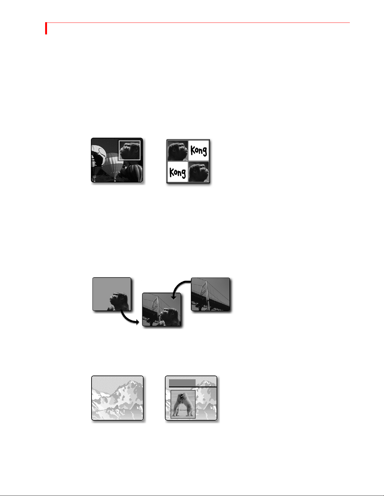
Chromakey — Keying replaces
parts of one picture with another,
based on their color. Here the solid
background behind Kong is replaced
by the picture of the bridge. The
chromakey version shows Kong contemplating the bridge.
Frame Synchronizer and Digital Video Mixer — Mix any two input sources together using a
variety of transitions — wipes, dissolves, flips, and so forth. With the frame synchronizer you can
mix independent video signals.
Compose — MX-4 DV provides a video
painting system you can use to combine video
stills, color shapes, and moving video on one
screen. You can create a screen that contains a
video still of a football coach (with a surrounding red border), combined with a moving video of the players in action on the field.
Audio Mixer — MX-4 DV provides sophisticated audio control. You can change the sound along
with the video, or play a constant sound while the video plays. Audio can come from a video
source or from external audio devices.
Page 7

INTRODUCTION MAJOR F EATURES
Connectivity — MX-4 DV provides multiple video/audio outputs, including one DV output, two
Y/C Program outputs, two composite Program outputs, one composite Preview output, two sets of
stereo audio outputs, and a Headphone output.
Joystick — The joystick gives you fine control over color adjustments and positioning of PIP (picture-in-picture), compose, and the chromakey cursor.
Color Correction — Apply true RGB color correction to any or all input sources. Color correction
parameters can be set separately for each channel.
Input Effects — Apply special effects such as flips, mosaics, and others to the signals coming in
from any input source. You now have the ability to adjust the brightness, contrast, color saturation
and hue on your input sources and thumbnails.
Still Frame Jpeg Images — For the ultimate in creative expression, let the MX-4 DV allow you to
trigger a stand-alone jpeg clips for background, input, or foreground use in your live video production programming. You can import and store up to 100 jpeg images (50 background and 50 foreground) using the Ethernet connection on the back of your unit.
Ethernet — You can network your MX-4 DV to a Mac or PC using an Ethernet (10Base-T) connector. You can import backgrounds, bugs and still frame jpegs to or from your unit.
Gradients — You can access eight gradients using the graphics menu.
3
Page 8

4
MX-4 DV USER GUIDE CHAPTER 1
COMMON USES FOR MX-4 DV
Multiple-Source Video Production — In a video production setup, you can connect one or more
video sources (VCRs, camcorders, video disc players, cameras, title generators, computer graphics
systems, and so forth) to MX-4 DV’s four input channels. The Program output can then be sent to a
VCR or directly to a monitor.
You can determine what is sent to the output. While the original inputs play, you can switch
between any of MX-4 DV’s channels. Use dissolves or other transitions to go from one channel to another. Add special effects to any channel, and use advanced features such as compose
and chromakey to enhance the production.
Single-Source Use — MX-4 DV supports A/A roll, a method for creating interesting transitions
with a single source. Its digital effects (such as picture freeze, posterization, and mosaic) give
added life to productions. You can use MX-4 DV with a titler to mix and superimpose titles. Time
base correction improves the picture (especially when making multiple-generation copies) by
removing the jitter common to most VCRs.
Live Video — In live production setups, MX-4 DV processes events as they occur. Good coverage
requires seeing the events from different vantage points—which means you need multiple input
sources. MX-4 DV gives you the ability to connect up to four sources simultaneously. For example, at a sporting event, camera one might focus on the playing field, camera two on the team
benches, camera three on the announcer, and camera four on the scoreboard. Using MX-4 DV you
can easily switch between the sources whenever necessary.
NOTE
MX-4 DV is not an edit controller — that is, it does not control VCRs, camcorders, and similar
devices. You can control the sources manually, or use external edit controllers such as those
manufactured by FOCUS Enhancements.
Page 9
INTRODUCTION MX-4 DV PACKAGE CONTENTS
MX-4 DV PACKAGE CONTENTS
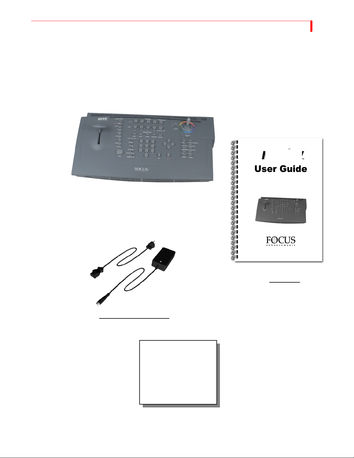
The MX-4 DV package contains the items shown below. Check your package against the illustration.
MX-4 DV Unit
MX-4 DV
5
POWER ADAPTER AND CORD
If your package doesn’t
contain all of the items
shown here, contact the
dealer where you purchased
the MX-4 DV for the
necessary replacements.
USER GUIDE
Product registration card
and other information
Page 10

6
MX-4 DV USER GUIDE CHAPTER 1
ABOUT THIS USER GUIDE
This User Guide contains the chapters, appendixes, and other sections shown in the following
table.
Table 1: User Guide Contents
CHAPTER DESCRIPTION
Chapter 1
Introduction
Chapter 2
Quick Start
Chapter 3
Installing MX-4 DV
Chapter 4
Basic Operations
Chapter 5
Transitions
Chapter 6
Input Effects
Chapter 7
Functions
Chapter 8
PIPs
Chapter 9
Compose
Basic overview of MX-4 DV features, description of
package contents, description of manual.
Brief steps to setting up MX-4 DV with your equipment. Provided for people quite familiar with connecting video equipment.
Instructions for setting up MX-4 DV to work with
your video equipment.
Explains most common procedures and functions used
with MX-4 DV.
Complete description of and instructions for using
MX-4 DV transitions. Also see Appendix A, Transitions List.
How to use various effects with video input material.
Descriptions of and instructions for using MX-4 DV’s
built-in functions.
Instructions for using the picture-in-picture functions.
How to create composed images consisting of rectangles, lines, still images, and/or moving images.
Chapter 10
Chromakey
Chapter 11
Learn Mode
Chapter 12
Working with Audio
Chapter 13
Advanced Operations
Appendix A
Transitions List
Appendix B
Time Base Corrector
Appendix C
Video Quality
Instructions for creating chromakey images where specific colors (such as a blue screen) can be keyed out
and replaced with a video sequence or other image.
How to use MX-4 DV’s Learn Mode for “recording”
your mixing steps then playing them back.
How to use audio sources (tapes, CDs, and so forth)
with MX-4 DV.
Descriptions of operations used infrequently, but still
of substantial use for mixing video programs.
Complete list of transitions available with MX-4 DV,
along with their assigned code numbers and descriptions.
Explains the time-base corrector feature built into
MX-4 DV.
Discusses issues concerning the level of quality in videos — that is, what to expect and what you can do to
improve quality.
Page 11
INTRODUCTION ABOUT THIS USER GUIDE
Table 1: User Guide Contents (continued)
CHAPTER DESCRIPTION
7
Appendix D
MX-4 DV product specifications.
Technical Specifications
Appendix E
Help for MXPro DV Users
Summarizes operational differences between MX-4
DV and FOCUS Enhancements’s Video Mixers.
Glossary Definitions of terms frequently used in conjunction
with MX-4 DV and video mixing procedures.
Index Standard index to topics in this manual.
Conventions The User Guide employs the conventions described in this section.
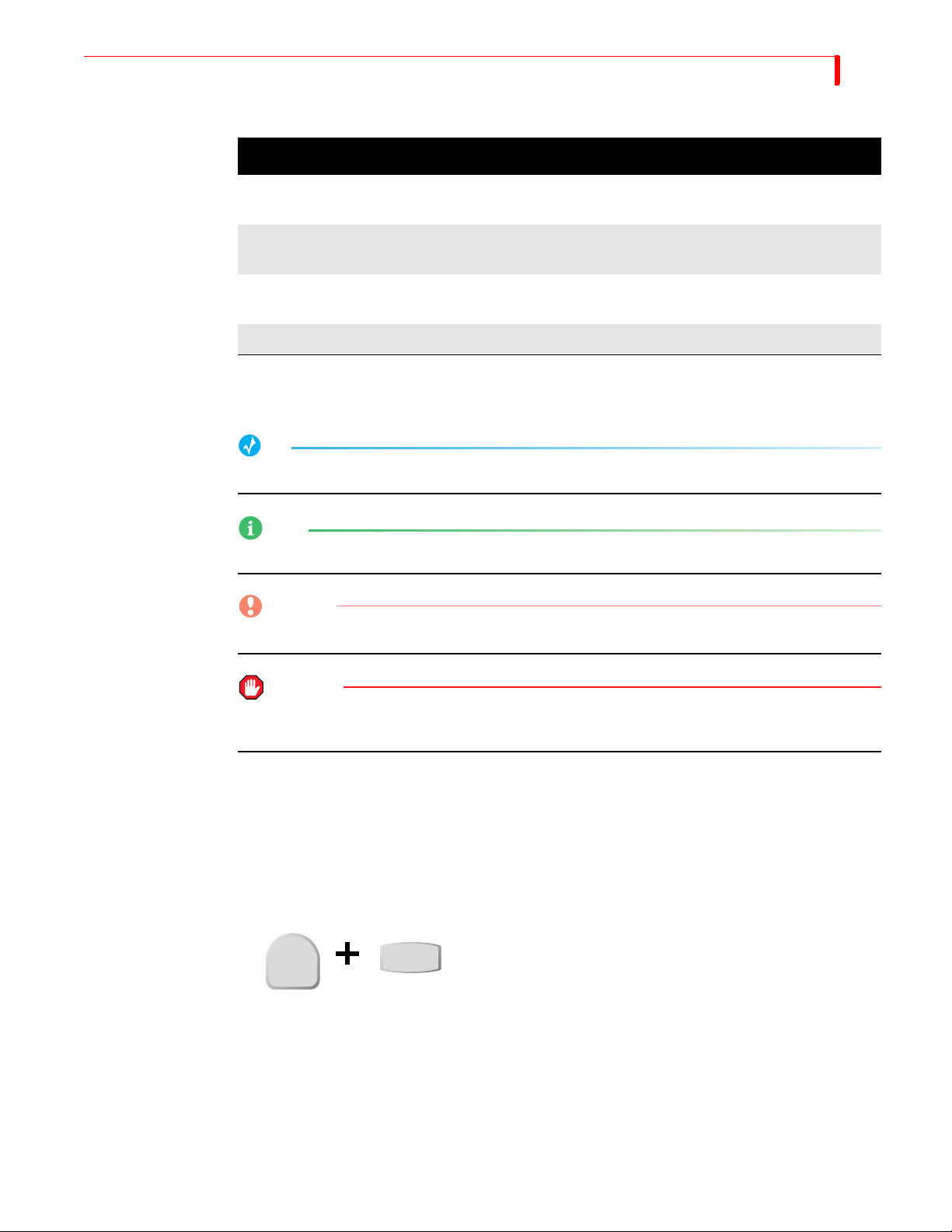
Tips, Notes, Cautions, and Warnings use the following formats.
TIP
A tip provides useful information for doing various tasks and procedures.
NOTE
Notes contain information to supplement the other information contained throughout the guide.
CAUTION
Cautions warn that if you continue with what you are doing there is a danger of losing information.
WARNING
Warnings mean stop what you are doing because there is danger of losing information and,
possibly, damaging your equipment.
MX-4 DV Buttons When referencing the various buttons (keys) and other controls on the MX-4 DV keyboard, they
appear in uppercase, boldface characters. For example, the keyboard contains the
T-BAR.
PLAY button and
In some cases you use two buttons together to perform a function. This is normally done using the
shift button in combination with some other button. A plus (+) symbol indicates this. For example,
SHIFT+PIPS to start MultiPIP mode. This means press and hold down
PIPs
Sources, Channels,
and Outputs
you might be asked to enter
SHIFT button, press the PIPS button, then release both.
the
SHIFT
The terms Source, Channel, and Output appear extensively throughout this guide. It’s important to
understand the differences between them.
A Source is a physical device, such as a VCR, that provides a video and/or audio signal.
A Channel is an internal MX-4 DV video signal path. The video and/or audio signal originating
from a source travels along one of the channels.
Page 12

8
MX-4 DV USER GUIDE CHAPTER 1
An Output displays or records a mixed signal (such as the video on one channel, a transition, and
the video on another channel) on an output device. The output device might be a recording VCR or
a live broadcast signal.
Page 13

CHAPTER 2
QUICK START
This chapter contains brief instructions for setting up MX-4 DV with basic equipment. The
instructions do not go into detail. If you feel comfortable connecting video and audio equipment, you can probably get started quickly using these instructions.
If you are upgrading from the Videonics MXPro DV, refer to Appendix APPENDIX E, Help
for MXPro DV Users, for helpful information in setting up your MX-4 DV.
Skim the instructions in this chapter. If you have any questions about any of the steps, turn to
Chapter 3, Installing the MX-4 DV, and follow the detailed instructions for setting up your
equipment.
Page 14
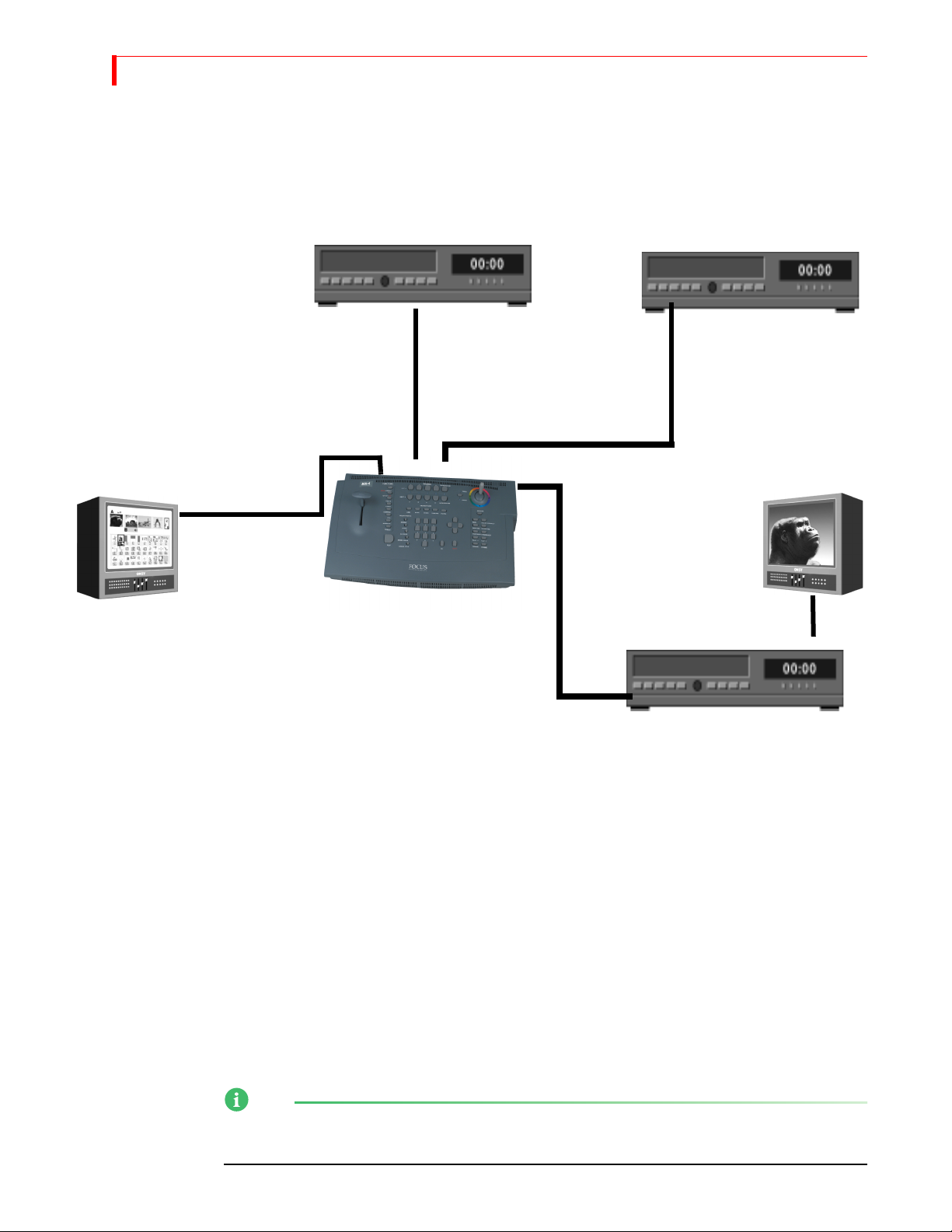
10
MX-4 DV USER GUIDE CHAPTER 2
QUICK START STEPS
Setting Up
Input Source Input Source
Preview Monitor
PREVIEW OUT
IN 1
IN 2
OUT 1
Output Monitor
Output Device
• Connect a COMPOSITE-type monitor to MX-4 DV’s PREVIEW OUT jack.
• Connect an Input Source (such as a VCR or camcorder) to the MX-4 DV’s DV IN 1 jack.
• Connect a second Input Source to the MX-4 DV’s Y/C IN 2 jack.
The MX-4 DV is set up, by default, to expect DV devices to be connected to the DV IN 1 and
DV IN 2 input jacks, and S-Video (Y/C) devices to be connected to the IN 1 and IN 2 input
jacks. If you connect a different assortment of input devices, you must tell the MX-4 DV this
fact. Refer to “Route” beginning on page 73 after completing the following steps.
• Connect an output device to the OUT jacks on the MX-4 DV rear panel. This is the
device where you record the program.
Remember, a DV connector carries the audio signal as well as the video signal. It is, therefore,
unnecessary to make separate connections for these signals when using a DV device as output.
• Connect a television or monitor to the recording VCR according to their instructions.
Having this monitor available lets you see exactly what is being recorded (or, output).
NOTE
These instructions assume there is a two-monitor setup. If you are using only one monitor, connect
it to PREVIEW OUT.
Page 15
QUICK START THE PREVIEW S CREEN
• Connect the MX-4 DV power supply to the power supply jack on the rear panel.
• Connect the MX-4 DV’s power cord to a suitable outlet.
• Turn on all devices (the MX-4 DV power switch is located on the right end of the unit)
and let the tapes roll.
For more detailed information about setting up your equipment, refer to Chapter 3, Installing the
MX-4 DV.
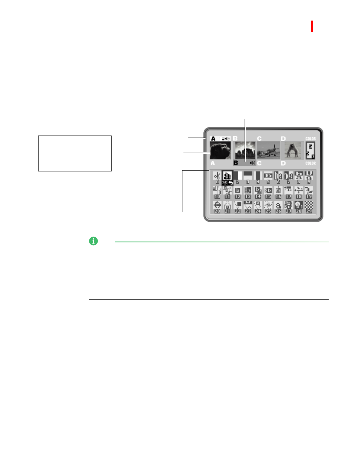
The Preview Screen
NEXT Source
CURRENT Source
You should see a Preview
screen similar to this on
your Preview monitor.
Previews
11
Transitions Menu
NOTE
The MX-4 DV provides a small preview screen in the user interface with the sources you have
attached. The images are scaled down in size, therefore, don’t play as smoothly as they would in a
single-source video monitor image. This does not affect the quality of the video going to the output
— it is always highest quality. In addition you will be able to view beforehand your source images
before running your transitions. Take advantage of the ability to adjust the Brightness, Color
Saturation, Contrast and Hue while viewing it on your preview screens. Refer to the video
adjustment menu section in Chapter 4 for these adjustments.
The PREVIEW screen contains the elements you need to run transitions:
CURRENT Source — The signal currently playing on your Output monitor. The MX-4 DV
highlights the CURRENT source in yellow (just above the preview images).
NEXT Source — The signal that will play on the Output monitor after the transition runs. The
MX-4 DV highlights the NEXT source in green.
Transitions M e n u — Rows and columns of icons representing some of the transitions available. The MX-4 DV highlights the currently selected transition in blue. The icons also show
the speed and direction for the selected transition.
Near the upper-right corner of the Preview screen is the color channel. The swatch uses numbers to
indicate the current background color, border color, and border style.
For more detailed information about controlling the content of the Preview screen, see “Using the
Preview Screen” beginning on page 35.
Page 16
12
MX-4 DV USER GUIDE CHAPTER 2
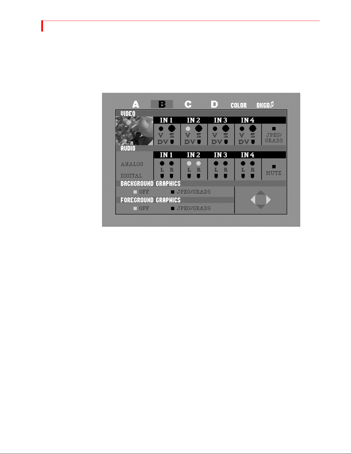
Using the Route
Function
The Route function ensures that the MX-4 DV understands where your input devices are connected
on the rear panel. If you connect Y/C devices to the IN1, IN2, IN3, and/or IN4 jacks, re-routing is
not necessary. Go on to the next section, “Running the Demo”.
• After starting the MX-4 DV with all devices connected and turned on, press ROUTE to display the Route screen.
Running the Demo
• Press the
LEFT ARROW or the RIGHT ARROW to select the appropriate input S
(Y/C), V (Composite), or DV.
• To route other inputs to different channels, press NEXT/X, where X represents the channel to which you want to route. Then repeat the preceding step.
• Press ROUTE again to exit from the Route screen.
The demo gives you a quick look at some of the MX-4 DV’s important features and assortment of
transitions.
•
Press the SHIFT+DEMO/DISPLAY buttons at the same time.
You should see the two sources alternating, with a variety of transition effects in between.
• Press any key to stop the demo at any time.
Page 17
QUICK START CUTTING BETWEEN SOURCES
Cutting Between Sources
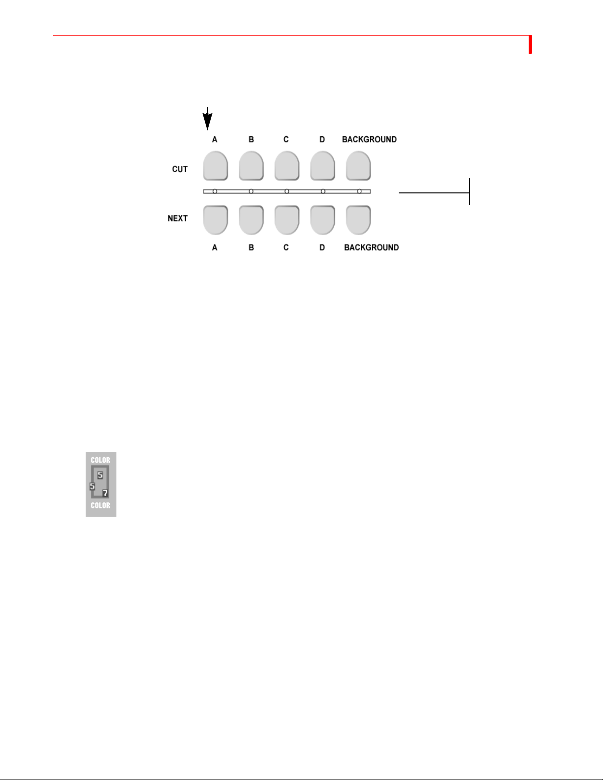
• Press CUT/A.
When you press a CUT button, the
small light below the button glows
steadily to indicate it is the CURRENT
source.
When you press a NEXT button, the
small light above the button blinks to
indicate it is the NEXT source.
The light below the A button comes on and the Output monitor displays the signal from whatever device is plugged into the inputs labeled IN 1. The yellow highlight above preview image
A tells you it is the currently active input.
Press CUT/B.
•
13
The light below the B button begins flashing (indicating B is both the CURRENT and NEXT
source) and the Output monitor displays the signal from whatever device is plugged into the
inputs labeled IN 2. The yellow highlight above preview image B tells you it is the currently
active input.
• If you have anything plugged into IN 3 or IN 4, press CUT/C and CUT/D, respectively, to
display their signals.
Borders and Solid Color Backgrounds
• Press CUT/BACKGROUND.
The MX-4 DV highlights the speaker, headphone, or color block above the channel indicator,
but does not show the channel letter. The Output monitor shows a solid color screen.
• To change the color, press
Each time you press the button the color changes in the background color sample and at the
Output. Continue pressing the button until you see a color you like.
• You can also define a border color and style to use at the edge of most transitions and
PIPs. Press
BORDER COLOR and the color around the background color sample shows
you the new choice. Press
Setting up a Transition
To set up a transition you need to select the sources you want to use and the transition you want to
use when switching between them. Here’s how to transition from source A to source B using a horizontal wipe.
• Press
• Press
• Use the
CUT/A to set A as the CURRENT source. The MX-4 DV shows a steadily glowing
light below the
NEXT/B to set B as the NEXT source (the one you want to see after the transition
CUT button you press.
finishes running). The LED light above the button you press flashes to indicate it is the
NEXT source.
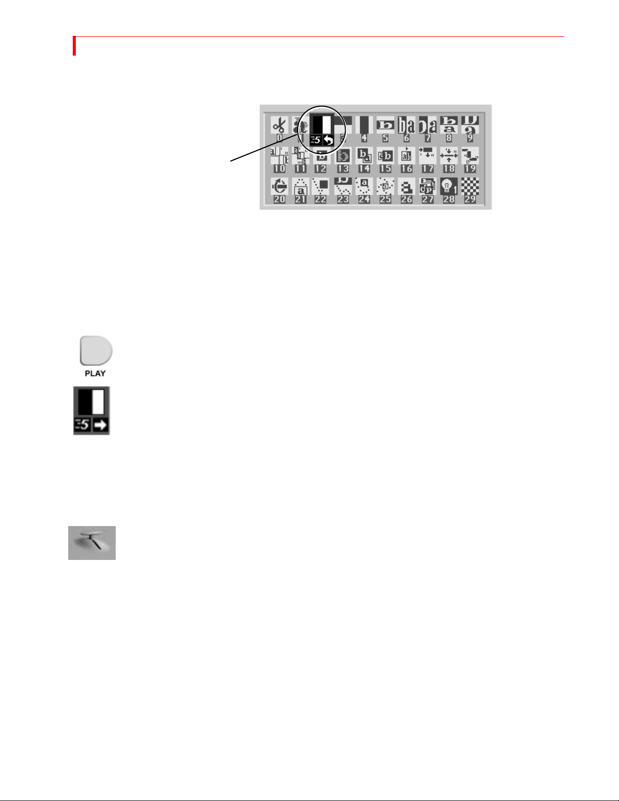
ARROW keys to highlight the Wipe transition in the Transitions Menu, as shown
in the following example.
BG COLOR.
BORDER STYLE to select from different styles for the border.
Page 18
14
MX-4 DV USER GUIDE CHAPTER 2
The MX-4 DV transitions between the two sources using the horizontal wipe transition with the
Output screen showing the results.
Running Transitions
You can run transitions automatically or manually.
Use LEFT and RIGHT ARROWS to move the selection horizontally. Use UP and DOWN ARROWS
to move the selection vertically: or, press 2 then
Selected Transition
OK to select the transition by number.
Automatic
Transitions
• Press PLAY. The MX-4 DV runs the transition at a pre-determined speed.
The MX-4 DV transitions between the two sources using the horizontal wipe transition with
the Output screen showing the results.
At the end of the wipe, B is on the OUTPUT monitor — it has become the CURRENT source. The
yellow highlight above the preview images has changed to reflect that. Furthermore, A is now the
NEXT source and the green highlight has been changed to A.
• To wipe back and forth between sources A and B, press PLAY repeatedly.
Speed
• To change the speed at which a transition runs, press the
cator under the transition icon changes.
• Press the button again until the desired speed appears. 0 is the slowest speed, 9 is the fastest.
• Try this with various speeds: Change the speed and press
Manual
Transitions
Use the TAKE BAR to run transitions and control their speed and direction.
•
Set up the transition as you would normally. However, instead of pressing PLAY, simply move
the
The transition begins running as soon as you move the
forth by moving the
Using CUT Transitions
SPEED button. The Speed indi-
PLAY.
T-BAR.
T-BAR. You can even move back and
T-BAR in different directions. Give it a try!
Most video productions use simple cuts a majority of the time. To cut between any two sources (for
example, you could cut from A to C to BACKGROUND to D), use the
There’s a quick way to cut back and forth between two sources using just the
of having to alternate between two
•
Press 0 and then OK to select transition 0, a simple cut.
CUT buttons:
CUT buttons.
PLAY button, instead
• Press PLAY again and again.
•
A solid color screen can be used as if it were a separate source. Press the NEXT/BACKGROUND
button and run any transition, or press CUT/BACKGROUND.
Page 19
QUICK START CHOOSING T RANSITIONS
Choosing Transitions
The Preview screen contains the Transitions Menu. This menu contains icons and other information for all MX-4 DV transitions. A blue highlight indicates the transition selected for the next
transition.
Select Transitions in the following ways:
•
ARROW keys – Simply use the arrow keys to highlight the desired transition.
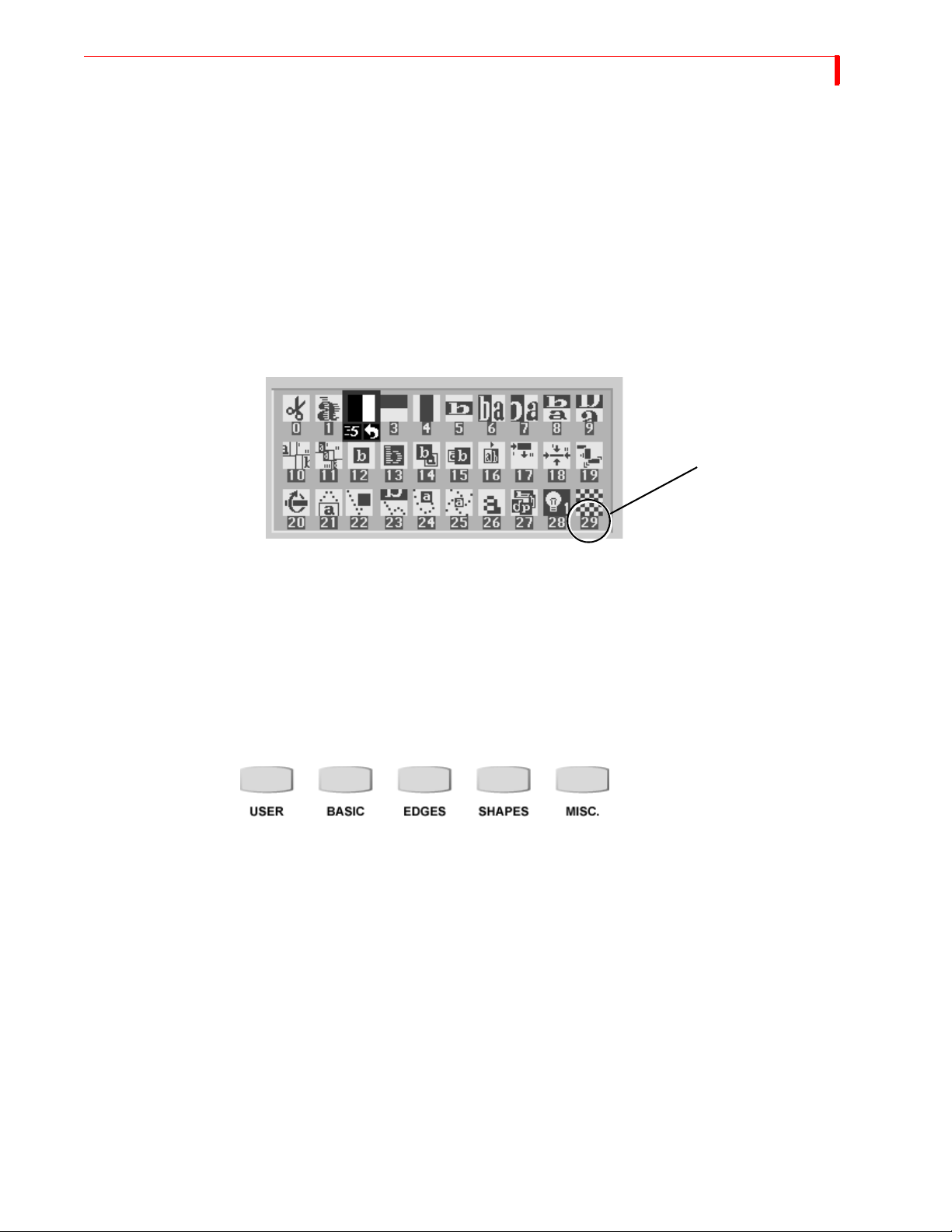
NUMBER keys – The MX-4 DV assigns a unique number to every transition. The number
appears below the transition icon on the PREVIEW screen (in the following example, the
checkerboard transition is number 29). You can use the number to select a transition. (When
you select/highlight a transition in the menu, the MX-4 DV shows the transition’s speed and
direction. At this point, the transition number is no longer visible.)
Transition Number 29
15
Enter 106 using the number keys (press 1, then 0, then 6), then press OK to highlight the tran-
•
sition icon.
The MX-4 DV replaces the current Transitions Menu and shows the one that contains the transition you selected.
•
Press PLAY.
Using Transition Categories
The MX-4 DV categorizes transitions into five major groups — User, Basic, Edges, Shapes, and
Misc. You can access any category at any time by pressing one of the Transition Category buttons.
When you press one of the buttons, the content of the Transitions Menu (see “The Preview Screen”
on page 11) changes.
• Press the
tion icons.
• Use the
• Press
The USER transition category is slightly different from the others. It originally contains a default
set of transitions, each of which also exists in the other categories. You can “tailor” the content of
the USER category to your specific needs and preferences. You’ll learn more about this in later
chapters.
PLAY or use the T-BAR to run the transition.
MISC. button. The Transitions Menu display a completely different set of transi-
ARROW keys to highlight a transition you’d like to see run.
Other Features
Refer to the rest of this User Guide to learn about the many additional MX-4 DV features, including:
Page 20

16
MX-4 DV USER GUIDE CHAPTER 2
• Using the DEMO/DISPLAY button to change the content of the Preview screen.
• Freeze the picture, and compress it.
• Separately control the sound.
• Apply input effects, such as mosaic, paint (posterization), negative, and more.
• Use chromakey to combine parts of one picture with parts of another.
• Compose your own pictures, made up of several stills, color rectangles, and a moving picture.
• Rearrange the inputs so A, B, C, and D, and their audio channels come from different rear
panel jacks.
• Memorize a sequence of transitions and play them back.
Page 21

CHAPTER 3
INSTALLING THE MX-4 DV
This chapter explains how to install (or, set up) MX-4 DV to use with other equipment.
Major topics include:
• Understanding Sources and Output
• Understanding Preview and Program monitors
• Understanding the MX-4 DV connectors
• Identifying Cables and Adapters you might need
• Installation examples
• Installing a Microphone
If you have experience with the Videonics MXPro DV, refer to APPENDIX E, Help for
MXPro DV Users, for information that will be helpful setting up your equipment.
Page 22
18
MX-4 DV USER GUIDE CHAPTER 3
SOURCES AND OUTPUT
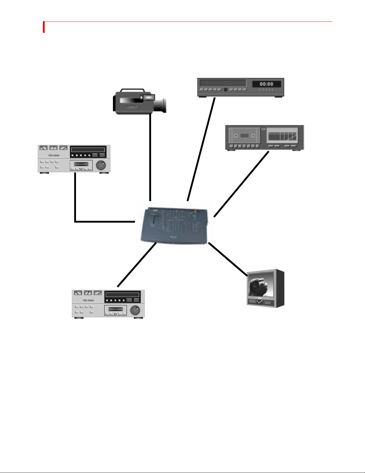
Source and Output refer to the way you use devices with MX-4 DV.
Source
Source
Source
Source
MX-4 DV
Output
Output
Source — A source is an input device. Each source provides a video signal, audio signal, or both.
You use the MX-4 DV to combine and (optionally) animate these signals.
Output — An output is a device on which you record and/or broadcast a signal. The signal might
contain video, audio, or both. This signal is often a mix of signals coming into MX-4 DV from one
or more sources. The output device might be a VCR with an optional monitor attached, or it might
be a live broadcast.
PREVIEW AND PROGRAM MONITORS
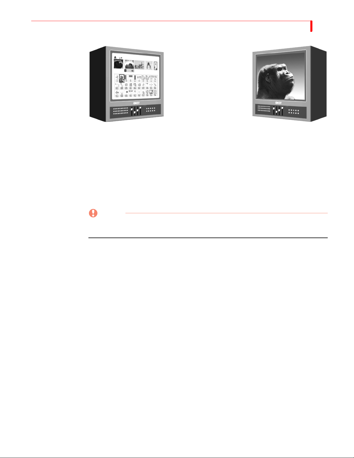
The MX-4 DV designates monitors as either Preview or Program to indicate how a particular mon-
itor may be used. This manual uses the following picture to distinguish between the two monitors.
Page 23
INSTALLING THE MX-4 DV PREVIEW M ONITOR
Preview Monitor Program Monitor
Preview Monitor
The Preview monitor is your “working” monitor. Most of the time it contains controls for managing Source and Output devices. For example, it shows miniature versions of images coming from
the attached VCRs and camcorders. The Preview monitor also shows a menu of transitions and
other effects from which you can choose. Refer to “Using the Preview Screen” beginning on
page 35.
19
Program Monitor
The Program monitor shows the production exactly as recorded on the output device or displayed
in a live video environment. The Program monitor shows the program complete with transitions
and other effects. You normally connect the Program monitor to the output device. The Program
monitor can be either a Composite, or Y/C device.
Number of Monitors
You can operate the MX-4 DV with only one monitor connected to the Preview out. However, to
greatly simplify your work you should have at least two monitors — one Preview and one Program. Instructions in this manual assume you have separate Preview and Program monitors.
CAUTION
The preview monitor must be a Composite device. Do not attempt to connect any other type
of monitor to the PREVIEW OUT jack on the MX-4 DV rear panel.
Page 24

20
MX-4 DV USER GUIDE CHAPTER 3
UNDERSTANDING MX-4 DV CONNECTORS
To properly setup the MX-4 DV, you need to know how and where to connect external components – such as VCRs, camcorders, and so forth. Use cables to connect video devices to the MX-4
DV’s rear panel. Refer to “Cables and Adapters” on page 22.
Remove the MX-4 DV from its package and set it so you can see the rear panel. Refer to the panel
and the illustration on the next page while reading this section.
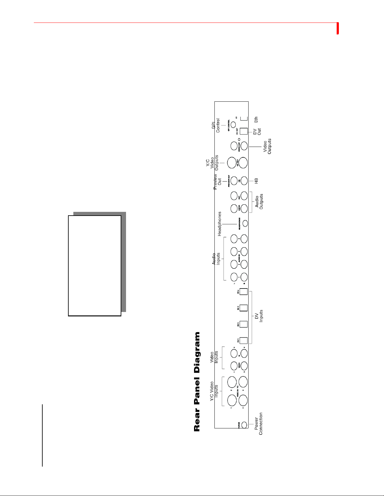
The MX-4 DV rear panel has numerous connectors and they vary by type. You can connect input
sources in any combination – up to a maximum of twelve – but you can use a maximum of four
devices at any given time. You can process just the video signal from a device, just the audio signal, or both.
You can connect four separate output devices to the MX-4 DV. You might, for example, direct one
output to a recording device and another to a live broadcast.
Note the labels associated with each connector on the MX-4 DV rear panel.
POWER — An electrical power connector. Use the power cord and adapter in the MX-4 DV
package to connect the unit to an electrical outlet.
Y/C IN— Connect Y/C sources to these connectors.
RCA IN — Connect composite sources to these connectors.
DV IN — Connect Digital Video sources to these connectors. Both the audio and video signal
is sent through these connections.
AUDIO IN — Connect audio devices to these connectors. Each set of connectors has L (Left)
and R (Right) jacks for stereo input. Refer to “Audio Connectors” on page 23.
HB IN — Connect a composite source such as a camera to lock on to and synchronize the
MX-4 DV with it.
GPI CONTROL — Connect a General Purpose Interface (GPI) device to this jack to control
the MX-4 DV from an external device or remote location. Refer to “Using a GPI Device”
beginning on page 120.
There are a total of eleven output connectors — one Preview, two composite, two S-Video, four
audio, and a Headphone jack.
PREVIEW OUT — Connect a composite video monitor to this jack. You cannot use an Y/C
monitor as Preview. This monitor serves as your visual “interface” with the MX-4 DV. It’s
where you do most of your work.
DV OUT — Connect a Digital Video output device. You record productions on this device,
use it to display a live broadcast signal or both. Both the audio and video signal are sent
through this connector.
Y/C OUT— Connect an Y/C output device. You record productions on this device, use it to
display a live broadcast signal, or both.
RCA OUT — Connect a composite output device. Same as above, but use this connector if
your output device is composite format.
AUDIO OUT — Connect a suitable audio cable or cables from these jacks to the audio inputs
on your output device. Refer to Chapter 12, Wo rk i n g wi t h A ud io , for a discussion of the dual
audio output features.
HEADPHONES — Refer to “Using Headphones” on page 25.
Page 25
INSTALLING THE MX-4 DV UNDERSTANDING MX-4 DV CONNECTORS
21
MX-4 DV REAR PANEL
familiarize yourself with the
Please take a few moments to
connections on the MX-4 DV Rear
your equipment.
Panel before you begin setting up
Page 26
22
MX-4 DV USER GUIDE CHAPTER 3
Power Connector
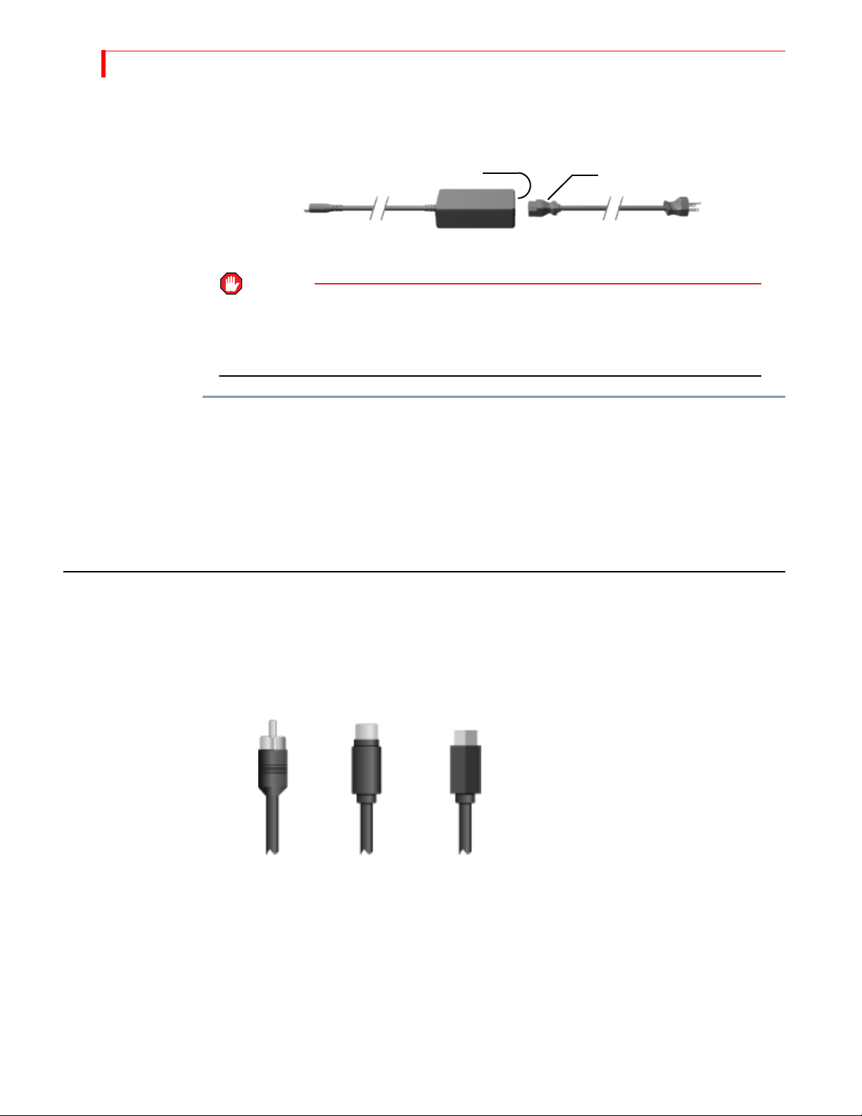
The MX-4 DV package contains the required transformer and power cord for the unit.
Male Socket Female Plug
Power
Adapter
Plug
Transformer Power Cord
WARNING
USE ONLY THE POWER CORD AND TRANSFORMER PROVIDED IN THE PACKAGE. DO NOT
USE THIS POWER CORD AND TRANSFORMER WITH ANY OTHER EQUIPMENT. FAILURE TO
OBSERVE THESE CONDITIONS CAN DAMAGE YOUR EQUIPMENT AND VOID YOUR
WARRANTY.
To connect the power cord and transformer:
1 Connect the female plug on the power cord into the male socket on the transformer.
2 Connect the male plug on the power cord to a suitable power outlet.
Male
Plug
3 Connect the power adapter plug on the transformer cord into the power connector on the MX-
4 DV rear panel.
4 Turn the MX-4 DV power switch (located on the right side of the unit) to the ON position.
CABLES AND ADAPTERS
To connect video devices to the MX-4 DV you need specific types of cables. You might also need
one or more adapters, depending on your equipment.
Look closely at the jacks on the MX-4 DV rear panel and note that they accept RCA Composite,
S-Video (Y/C), or Digital Video (DV)cables.
RCA
Composite
S-Video
(Y/C)
Digital Video
Connector
Before connecting any device to the MX-4 DV, make sure the cable you are using has the right
type of fitting for the jack you intend to use.
Page 27
INSTALLING THE MX-4 DV CABLES AND A DAPTERS
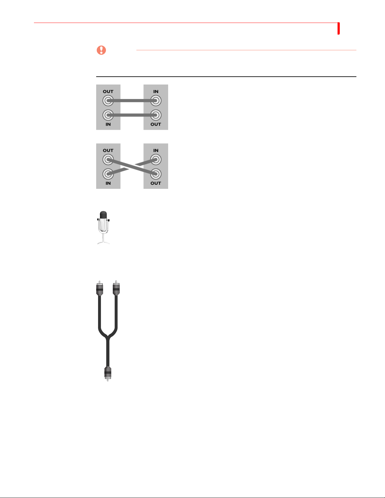
CAUTION
When making connections, always connect the OUT from one device to the IN on the other
device. NEVER connect OUT to OUT or IN to IN
GOOD!
BAD!
Microphones You can connect a microphone to any MX-4 DV input jack, but you may need a spe-
cial adapter to make the connection. The type of adapter needed varies depending on
the type of microphone you want to use. If you do not have the adapter you need,
take your microphone to a local electronics supply store to make sure you select the
correct adapter.
23
Audio Connectors To connect a stereophonic audio device to the MX-4 DV, you need two separate audio cables —
one for the left channel and one for the right.
To connect a monaural audio device you need a Y-adapter cable (like the one shown
at the left). Connect the single end of the adapter to the line input or output on the
device. Connect the two remaining ends to the left and right channel inputs or outputs on the MX-4 DV rear panel.
The Y-adapter cable does not provide stereophonic audio. It simply directs the mono
signal to or from both MX-4 DV channels.
You can also connect a mono audio device, then connect the other end to either the
left or right connector on any MX-4 DV audio input. Once connected, use the MX-4
DV ROUTE function to specify which connector (left or right you used. Refer to
“Route” beginning on page 73.
Page 28
24
MX-4 DV USER GUIDE CHAPTER 3
INSTALLATION EXAMPLES
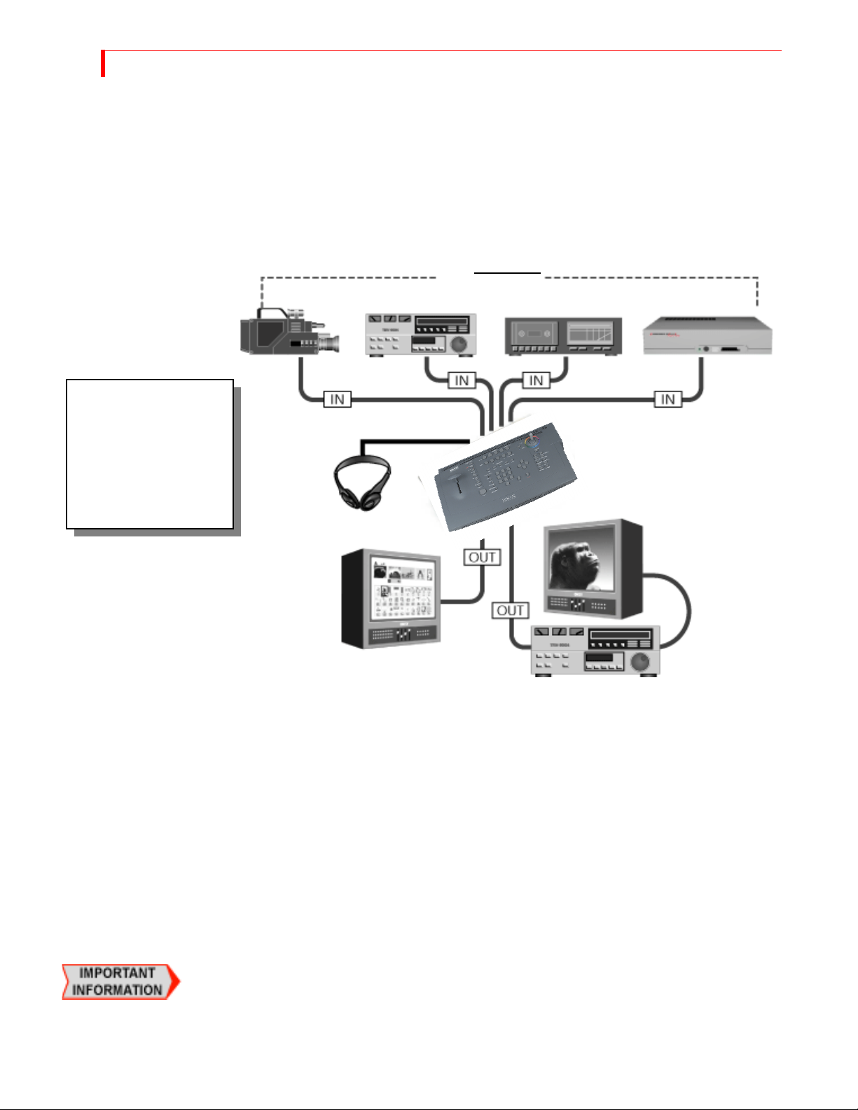
This section shows examples of two common MX-4 DV configurations, but does not describe
every possibility. Before proceeding, study the following diagram (MX-4 DV Installation Concept)
that shows overall configuration concepts.
MX-4 DV Installation Concept
This diagram illustrates
the overall concept for
installing equipment with
MX-4 DV. Please study it
before you begin
installing your own
equipment.
Channel
Preview
Channel
A
B
SOURCES
Channel
C
Channel
D
Headphones
Program
You can have up to four separate audio/video input sources active at any given time. The MX-4
DV designates them as sources A, B, C, and D. You can use any mix of devices as necessary to
complete your work so long as they are valid MX-4 DV devices. For example, you can use VCRs,
VTR’s, camcorders, laserdisc players, satellite tuners, broadcast tuners/receivers, character generators (CG’s), video-equipped computers, and audio devices (such as a CD player or tape deck).
The MX-4 DV sends the output signal to a recording device (such as a VCR) and/or a Program
monitor.
Use a second monitor, Preview, to display preview images of all input sources. The Preview monitor also displays the on-screen controls you use to operate MX-4 DV. The Preview monitor is
required for operation.
Correlating Input Sources to MX-4 DV Jacks
As stated above, the MX-4 DV designates your input sources as A, B, C, and D. However, if you
examine the jacks on the MX-4 DV rear panel, you’ll see they are labeled 1, 2, 3, and 4. Initially,
there is a direct correlation between the letter and the number designations: jack 1 corresponds to
source A, jack 2 corresponds to source B, jack 3 corresponds to source C, and jack 4 to source D.
You can re-route inputs to other channels. For more information, refer to “Route” beginning on
page 73.
Output
Page 29
INSTALLING THE MX-4 DV USING H EADPHONES
Using Headphones
To use headphones, connect them to the Headphone jack, which is located on the middle of the
unit. The jack accepts standard stereo headphones with a miniature plug. If your headphones have
a large plug, you need an adapter to switch it to a miniature plug.
VCR Selector Switches
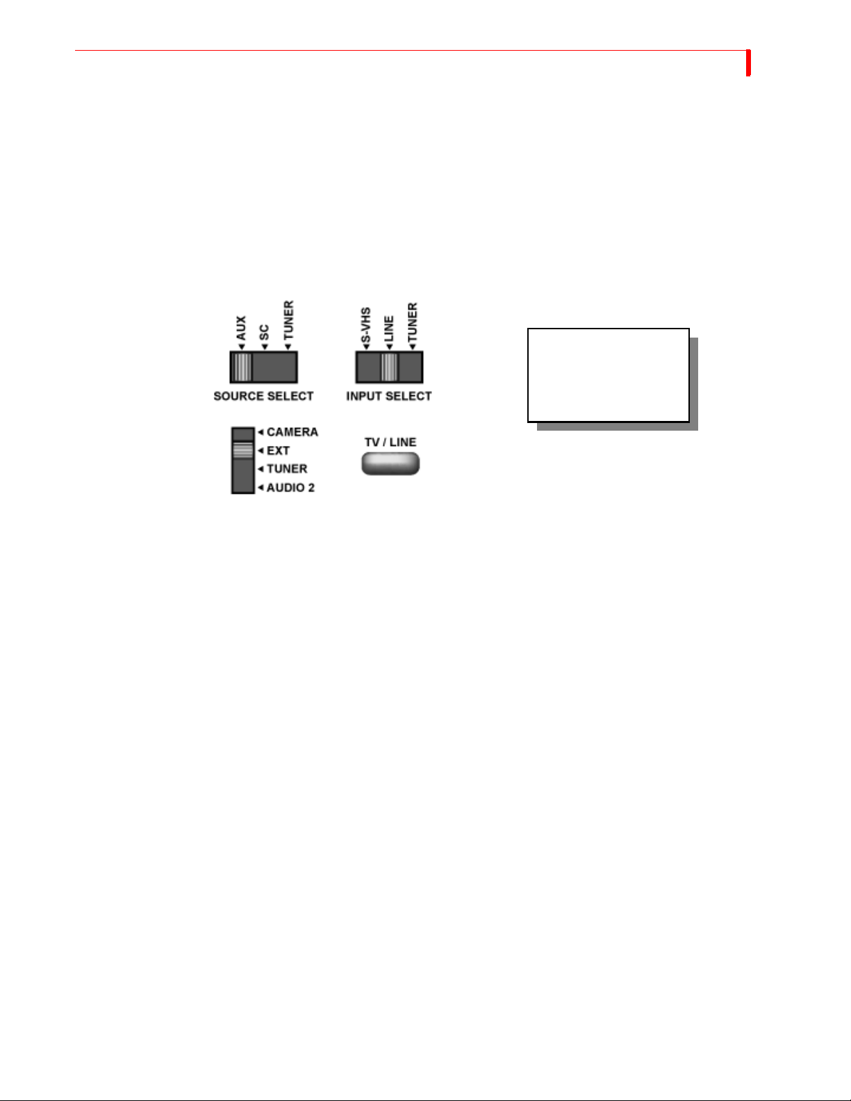
Many VCRs have an input selector switch that routes between Line (or AUX, EXT, A/V, or S) and
Tuner. Here are some examples.
If a device has a switch
similar to one of these,
set the switch to the
LINE position.
25
General Notes
Some VCRs have more than one VIDEO IN jack (for example, one might be Composite and the
other Y/C). Set the switch to match the jack you are using as the connector to the MX-4 DV.
When connecting video and audio outputs from source devices, most of the time you’ll probably
connect to corresponding jacks on the MX-4 DV rear panel. For example, if you connect the video
to the VIDEO IN jack labeled “1,” you’ll most likely connect the audio to the AUDIO IN jack also
labeled “1.” However, this is not a requirement. You might use non-corresponding jacks — for
example, you might connect the video from one source to VIDEO IN 1 but connect the audio from
the same source to AUDIO IN 2 if you want to control the audio and video separately.
Remember, DV devices carry the audio and video signal (as well as a machine control signal) on
the same connection.
Page 30

26
MX-4 DV USER GUIDE CHAPTER 3
Post Production Configuration
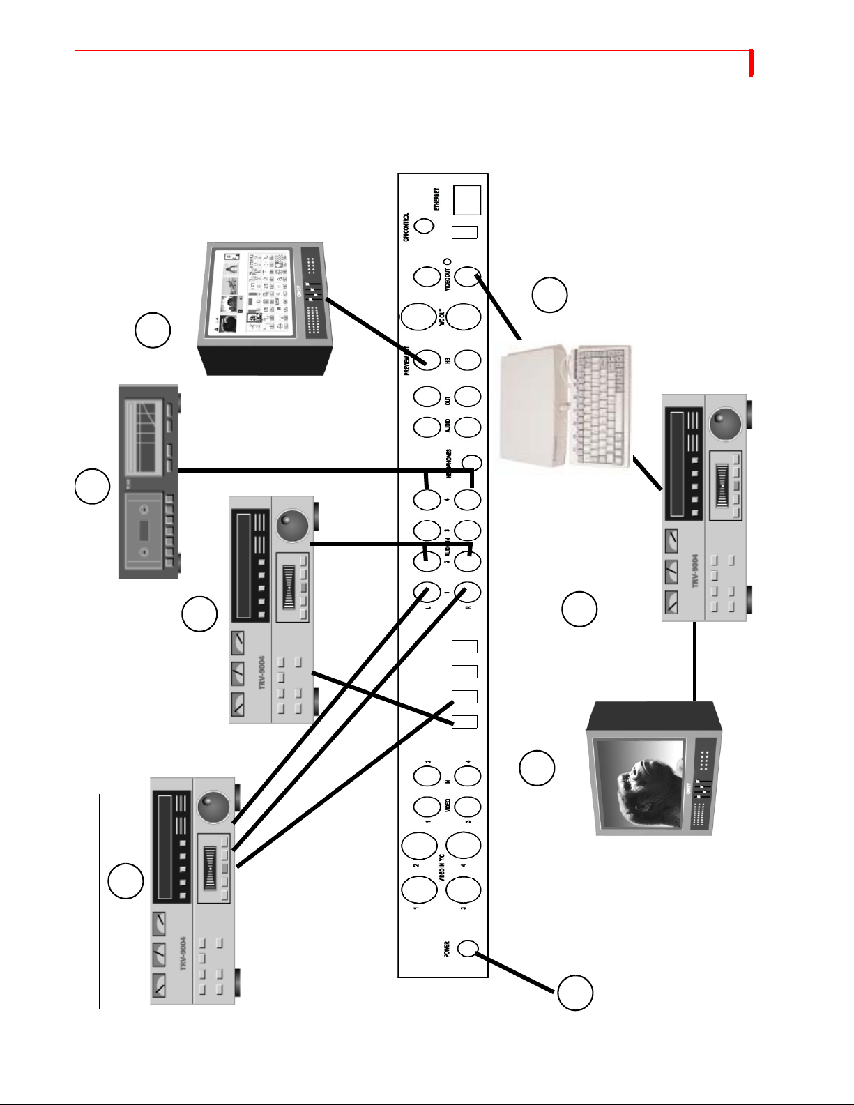
This configuration is useful in a Post-Production environment—where you mix two or more programs together.
This installation example below shows the use of DV equipment in combination with analog
equipment.
1 Connect the VIDEO OUT from a DV VTR 1 to DV IN 1 on the MX-4 DV rear panel.
Connect the AUDIO OUTs from a DV VTR 1 to AUDIO IN 1 on the MX-4 DV rear panel.
2 Connect the VIDEO OUT from a DV VTR 2 to DV IN 2 on the MX-4 DV rear panel.
Connect the AUDIO OUTs from a DV VTR 2 to AUDIO IN 2 on the MX-4 DV rear panel.
3 OPTIONAL – Connect an audio source (CD player, tape deck, or microphone) to AUDIO IN
4 on the MX-4 DV rear panel.
4 Connect a Composite-type monitor to the PREVIEW OUT jack on the rear panel.
5 OPTIONAL - Connect a Character Generator (CG) to the OUT Y/C jack on the rear panel.
With this configuration you can superimpose titles from the CG atop the output signal.
6 Connect a recording VTR to the OUT Y/C jack on the rear panel.
If you are using the optional Character Generator (described above), connect the output from
the CG to the VTR input.
7 Connect an Output Monitor to the recording VTR so you can see the signal being recorded.
8 Connect the power cord and transformer to the MX-4 DV rear panel. Refer to “Power Connec-
tor” on page 22 for instructions.
Use the Route function (“Route” beginning on page 73) to make sure your devices are directed to
the correct MX-4 DV channels.
Page 31
INSTALLING THE MX-4 DV POST PRODUCTION CONFIGURATION
DV Out
Preview
Monitor
5
4
27
3
2
DV IN
6
7
Monitor
Program
1
POST PRODUCTION CONFIGURATION
8
Page 32

28
MX-4 DV USER GUIDE CHAPTER 3
Live Broadcast Configuration
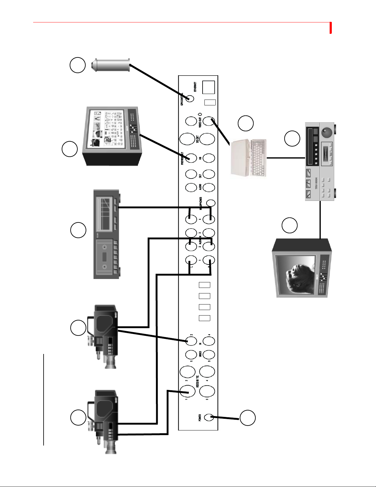
This configuration is useful in a Live Broadcast environment.
1 Connect the VIDEO OUT from Camera 1 to VIDEO IN 1 (Y/C) on the MX-4 DV rear panel.
Connect the AUDIO OUTs from Camera 1 to AUDIO IN 1 on the rear panel.
2 Connect the VIDEO OUT from Camera 2 to VIDEO IN 2 on the MX-4 DV rear panel. Con-
nect the AUDIO OUTs from Camera 2 to AUDIO IN 2 on the rear panel.
3 OPTIONAL – Connect an audio source (CD player, tape deck, or microphone) to AUDIO IN
4 on the MX-4 DV rear panel.
4 Connect a Composite MV-4 -type monitor to the PREVIEW OUT jack on the rear panel.
5 OPTIONAL – Connect a GPI trigger device to the GPI CONTROL on the MX-4 DV rear
panel.
6 OPTIONAL – Connect a character generator (CG) to the OUT Y/C jack on the rear panel.
With this configuration you can superimpose titles from the CG atop the output signal.
7 Connect a recording VTR to the OUT Y/C jack on the rear panel.
If you are using the optional Character Generator (described above), connect the output from
the CG to the VTR input.
8 Connect the Output Monitor to the recording VTR so you can see the signal being recorded.
9 Connect the Power Cord and Transformer to the MX-4 DV rear panel. Refer to “Power Con-
nector” on page 22 for instructions.
Use the Route function (refer to page 73) to make sure your devices are directed to the correct MX4 DV channels.
Page 33
INSTALLING THE MX-4 DV LIVE BROADCAST CONFIGURATION
5
DV Out
6
Preview
Monitor
7
4
29
8
Monitor
Program
DV IN
1 2 3
LIVE BROADCAST CONFIGURATION
9
Page 34
30
MX-4 DV USER GUIDE CHAPTER 3
USING A MICROPHONE WITH MX-4 DV
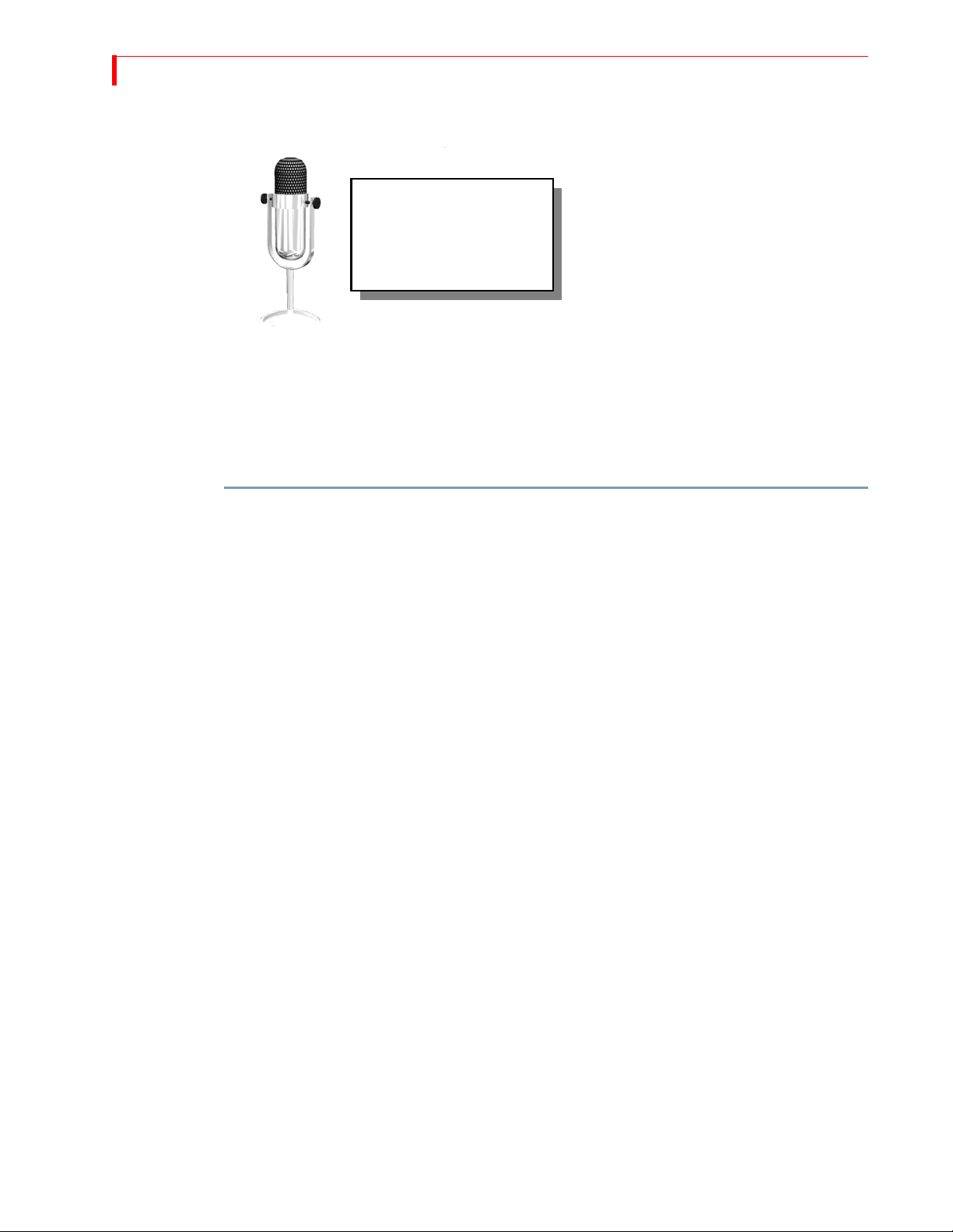
This section explains how to
connect a microphone to
MX-4 DV. You’ll need the
equipment listed below…
• Professional quality microphone
• Microphone cable (male-XLR to female-XLR connectors)
• An audio direct box (which you can purchase from any professional audio equipment dealer)
• A 1/4 inch (phone jack) to RCA cable
• A female RCA to dual-male RCA “Y” Adapter
To connect a microphone:
1 Using the microphone cable, connect it to the XLR (balanced) input on the Direct Box.
2 Plug the 1/4-inch-to-RCA cable into the 1/4-inch (unbalanced) output on the Direct Box.
3 Attach the RCA “Y” adapter to the 1/4-inch-to-RCA cable.
4 Plug the two male ends of the RCA “Y” Adapter into the R and L audio inputs on the MX-4
DV rear panel. You can plug the microphone into any audio input and route it like any other
source.
Page 35

BASIC OPERATIONS
This chapter describes several basic MX-4 DV operations, including:
• Starting and stopping the MX-4 DV
• Using the MX-4 DV keyboard
• Using the Preview screen
• Using CURRENT and NEXT sources
• Selecting Sources
• Using the VIDEO/AUDIO selector
• Cutting Between Sources
• Working with Color
• Using Backgrounds
•Using Borders
CHAPTER 4
Page 36

32
MX-4 DV USER GUIDE CHAPTER 4
STARTING AND STOPPING THE MX-4 DV
Press the Power switch to start or stop the MX-4 DV. The switch, located on the right-end of the
unit, is a rocker-type switch.
UNDERSTANDING THE KEYBOARD
Use the MX-4 DV keyboard to control how the unit operates.
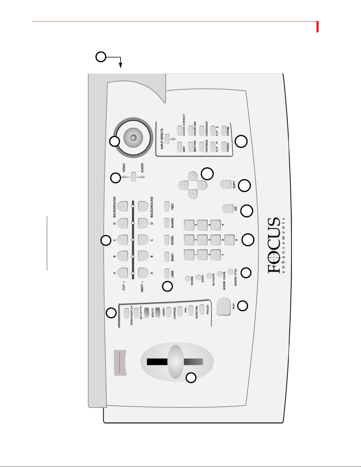
This section briefly describes the button groups and, in some cases, individual buttons and controls. Additional information appears throughout this User Guide. Some of the following descriptions provide a reference to the page where you can find details. Refer to the illustration on the next
page while reading this material.
1 T-Bar (or, Take Bar) — Use to manually control the way transitions run, tile size in PIP
mode, and audio levels in the Audio Mixer. Refer to Chapter 5, Transitions, Chapter 8, PIPs,
and Chapter 12, Working with Audio, respectively. The
ment sliders.
T-BAR also controls the video adjust-
2 Function Buttons — Provide immediate access to built-in functions, including
SETUP, FTP, ROUTE, LEARN, COMPOSE, PIPS, AUDIO MIX, and FREEZE. You can also access
the built-in demo using the
SHIFT+DEMO/DISPLAY buttons. Refer to Chapter 7, Functions, for
DISPLAY,
details.
3 Source Selectors — Use to select the CURRENT (
CUT) and NEXT sources for a production.
Normally, you select the CURRENT and NEXT sources, select a transition to use between the
two, then run it. For example, you might select a camcorder as one input source (CURRENT)
and a VCR as the other (NEXT). You then select a transition, such as a dissolve or wipe. When
you reach the point in the CURRENT source where you want to change to the NEXT source,
PLAY or use the T-BAR to instruct the MX-4 DV to play the transition. The CURRENT
press
source becomes the new NEXT source, and the old NEXT source becomes the new CURRENT source. (See “Using CURRENT and NEXT Sources” beginning on page 38.) Use the
COLOR buttons to create solid colored backgrounds and other effects. (Refer to “Working with
Colors” beginning on page 41.)
4 Video/Audio Selector — Determines whether VIDEO, AUDIO, or both VIDEO and AUDIO
are affected when you run a transition. When set to
does not. When set to
AUDIO, the audio changes but the video does not. When set to both, the
VIDEO, the video changes but the audio
video and audio both change. Refer to “Using the Video/Audio Selector” on page 39.
5Joystick — Provides an easy way to make fine adjustments to various components. For exam-
ple, when using PIPs, the joystick positions the various picture elements on the screen. When
using color correction, the joystick adjusts the color. The joystick has other uses you’ll learn
about in later chapters.
6Power Switch — The Power switch is a rocker-type switch for turning the unit on and off.
7 Transition Category Buttons — Gives you immediate access to the five, major categories of
transitions, including
USER, BASIC, EDGES, SHAPES, and MISC. All MX-4 DV transitions fall
into one of these categories. After pressing a button, you can search through the transitions in
that category to find the one you want to use. Refer to “Transition Categories and Menus”
beginning on page 50.
8 Play Button — Press to invoke the next command and complete a transition you have set up.
In other words, set up your CURRENT and NEXT sources, select a transition, then press
PLAY
at the moment you want the MX-4 DV to perform the step.
Page 37
BASIC OPERATIONS UNDERSTANDING THE KEYBOARD
6
33
MX-4 DV KEYBOARD
5
4
13
14
12
11
3
10
9
7
8
2
1
Page 38

34
MX-4 DV USER GUIDE CHAPTER 4
9 Control Buttons — Use these buttons to reverse transition direction, change transition speed,
specify background and border colors, and set border styles.
10 Numeric Keypad — Use for various functions, such as entering the number of a transition
you want to use, setting a precise speed for a transition, and so forth.
11 OK Button — Generally used to indicate to the MX-4 DV that you have completed some
operation and want the unit to prepare for or perform it accordingly.
12 SHIFT Button — A modifier key that invokes special functions when used in conjunction
with other keyboard keys.
13 Arrow Keys — Primarily used for selecting effects and functions. For example, use the arrow
keys to highlight a transition you want to use in the Transitions menu.
14 EFFECTS Buttons — Provides access to effects you can apply to input sources. The light
below the
EFFECTS button glows when the MX-4 DV is in Input Effects mode. Refer to Chap-
ter 6, Input Effects, for more information.
Page 39
BASIC OPERATIONS USING THE PREVIEW SCREEN
n
USING THE PREVIEW SCREEN
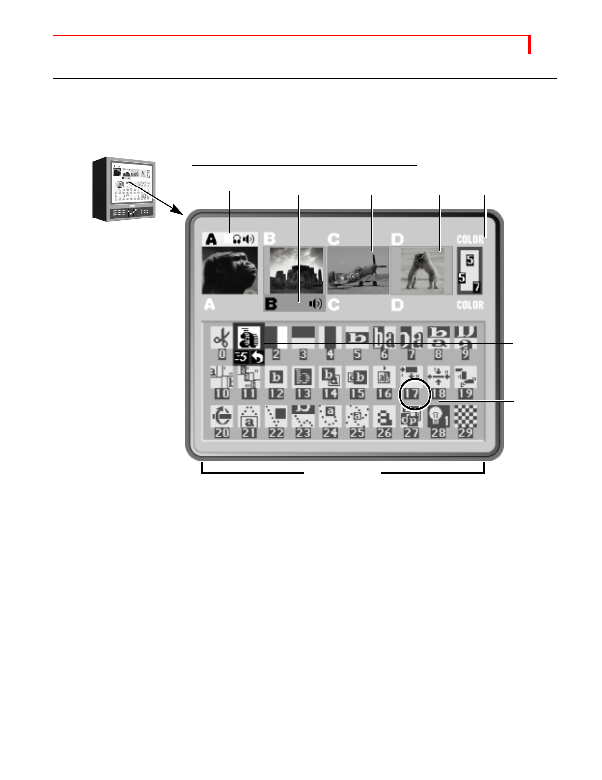
The Preview Screen is your control center for the MX-4 DV operations. This section describes
individual items on the Preview screen. The Preview screen appears on the monitor attached to the
MX-4 DV PREVIEW OUT jack.
PREVIEW MONITOR AND STANDARD PREVIEW SCREEN
35
Active Source Highlights
Input Source Previews
Color
Selector
Select
Transition
Transition
Number
The MX-4 DV always processes the output at the highest possible quality. The Input Source
Previews, however, appear in reduced quality because the MX-4 DV must reduce the images to fit
the smaller window. What you see on the Preview screen is not indicative of what gets recorded or
displayed on the output.
Changing the Display Configuration
Press the DISPLAY button to repeatedly cycle through five different configurations for the Preview
screen, or use the shortcut key indicated for each:
• Standard — (SHIFT+1) Shows preview images for all four input sources and up to 30 different
transition options (as shown above).
• Two Channel — (
views and two rows of the Transitions menu.
• Full – (
SHIFT+3) Displays only the input source Preview windows, each in a larger size. Tran-
sitions menu not displayed.
SHIFT+2) Shows only enlarged CURRENT and NEXT input source Pre-
Transitions Menu
Page 40
36
MX-4 DV USER GUIDE CHAPTER 4
• Next — (SHIFT+4) Displays full-screen image of the NEXT input source. Transitions menu
not displayed.
• Current — (
menu not displayed.
Refer to “Display” beginning on page 69 for more information. Unless stated otherwise, this guide
assumes you are using the Standard preview.
Input Source Previews
A small, preview image from each input source appears in a separate window. Use the previews to
direct the action, position cameras, find a particular sequence on a video tape, and so forth. Input
effects can be viewed in the preview thumbnail images.
Active Source Highlights
You can have up to four input sources. The MX-4 DV labels the sources A, B, C, and D. (There is
also a fifth, built-in source — the mixer’s own background color generator.) All transitions start
with one source, called the CURRENT source, and end with another, called the NEXT source.
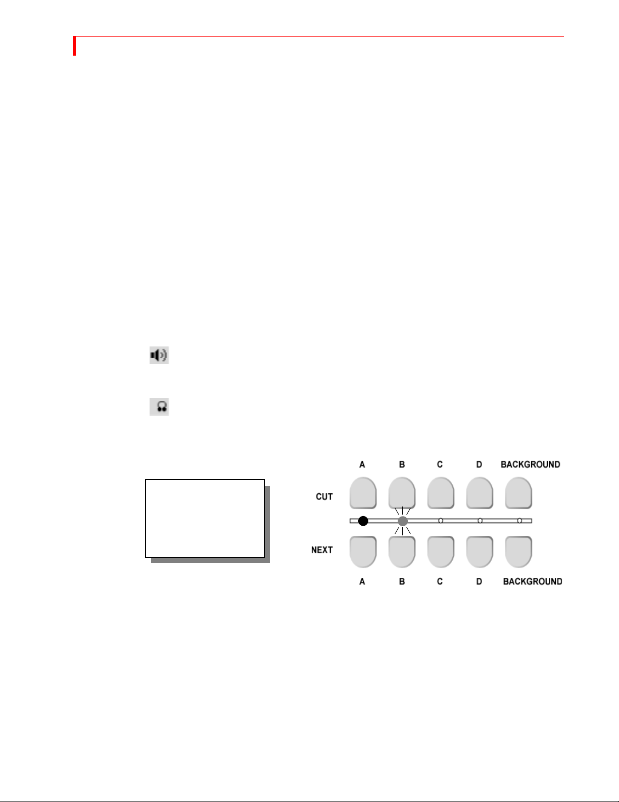
Colored highlights help identify one video source from another. Yellow highlights the CURRENT
video source (above the preview image), and green highlights the NEXT video source (below it).
SHIFT+5) Displays full-screen image of the CURRENT input source. Transitions
The speaker icon (rather than a colored highlight) indicates the CURRENT and NEXT
audio selections.
The headpins icon identifies the channel to which the headphone output is currently
directed.
In addition to the highlights described above, indicator lights between the
CUT and NEXT
buttons indicate the currently selected video sources.
A steady light identifies
the CURRENT video
source. A blinking light
identifies the NEXT video
source.
Brief descriptions of the Transitions Menu, Highlights, and Indicators follow. For more detailed
information, refer to Chapter 5, Transitions.
Page 41
BASIC OPERATIONS COLOR S ELECTOR
Color Selector
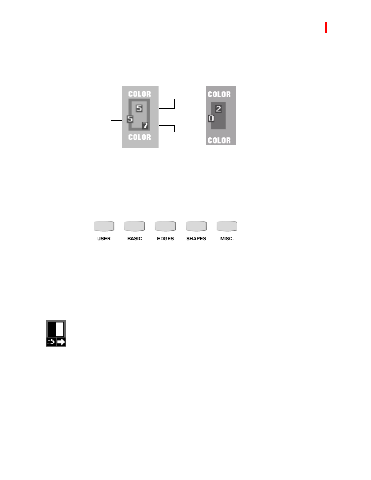
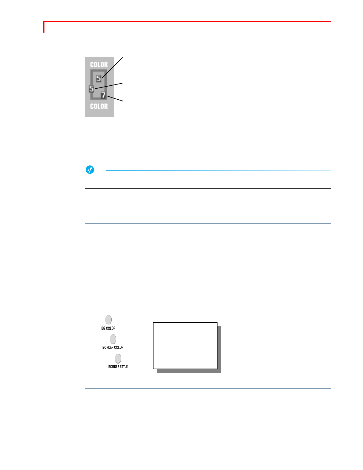
The Color Selector shows current choices for background color, border color, and border style. The
selector shows the actual colors, and the numeric values associated with each. This example shows
a background color 5, border color 7, and border style 5.
Background
Color
If you turn off the border (that is, set the
Border
Style
Border
Color
border style to zero), the border color
swatch and number do not appear in the
Color Selector. However, the border style
number (which is 0) is shown.
37
You can cycle through all available colors for each component using the
COLOR, and BORDER STYLE buttons. Refer to “Working with Colors” beginning on page 41.
Transitions Menu
The Transitions menu shows up to 30 transitions at a time. The MX-4 DV groups the 700+ available transitions into categories.
To access any transition category, press the appropriate transition category button.
Refer to “Transition Categories and Menus” beginning on page 50 and Appendix A, Transitions
List, for detailed information.
Use the
more transitions than can appear in the Transitions menu at one time, continue pressing
ARROW or UP ARROW to scroll the other transitions into the menu. When the transition you want
appears in the Transitions menu, use the
Selected Transition
When you select a transition in the menu, the MX-4 DV highlights it in blue. It also shows the current speed and direction for the transition. In this example, speed is 5 and the direction is forward
(as indicated by the arrow).
BG COLOR, BORDER
ARROW keys to navigate through the transitions in the current menu. If a category contains
DOWN
ARROW keys to select (or, highlight) it.
You can change the speed at which a transition runs, and you can also change the direction in
which it runs. Refer to “Adjusting Transitions” beginning on page 56.
Page 42
38
MX-4 DV USER GUIDE CHAPTER 4
Using CURRENT and NEXT Sources
The concept of CURRENT and NEXT sources is fundamental to MX-4 DV operations. As you go
about creating productions, you always have a CURRENT and NEXT source.
Example…
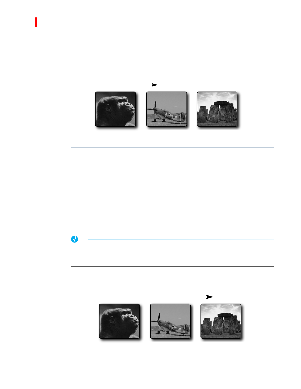
Suppose you want to create a sequence of transitions from Kong’s thoughtful gaze to footage of
a fighter plane contemplating take off and, finally, a shot of Stonehenge for a mystic closing.
CURRENT NEXT
Source A Source B Source C
To identify the CURRENT and NEXT sources:
1 Begin with the footage of Kong. Press CUT/A to make this (Source A) the CURRENT source.
2 Press
NEXT/B to make the fighter plane (Source B) the NEXT source.
3 Select a transition to use when switching from the CURRENT to NEXT source, such as a
right-to-left wipe.
Use the
ARROW keys to highlight the transition in the Transitions Menu. Refer to “Selecting
Transitions” beginning on page 54 for additional methods of selecting transitions.
Roll the CURRENT source to the spot where the transition should run, then press PLAY.
4
Immediately upon completion of the transition, the MX-4 DV makes the CURRENT source
(Kong) the NEXT source, and makes the NEXT source (the fighter plane) the CURRENT
source.
TIP
You can use this automatic swapping of CURRENT to NEXT and vice versa to your advantage.
When you want to cut back and forth between only two sources, the automatic swapping always
selects the next source for you.
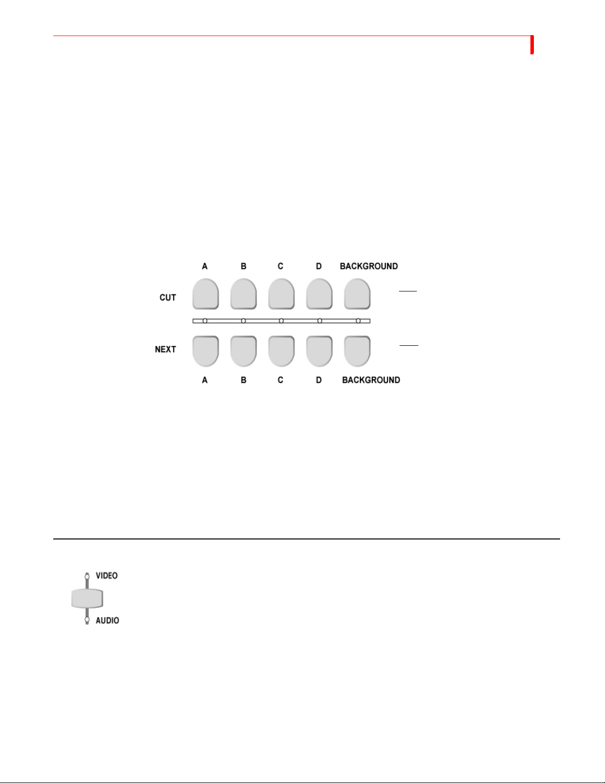
For this procedure, however, you need to make Stonehenge the NEXT source so that when
transitioning out of the fighter plane, Stonehenge comes on screen.
Press NEXT/C to select Stonehenge as the NEXT input source.
5
CURRENT NEXT
Source A
Source B
Source C
Page 43
BASIC OPERATIONS SELECTING S OURCES
6 Select a transition to use this time to switch from CURRENT to NEXT source, such as a slow
dissolve. The CURRENT source (the fighter plane) continues running, and continues to appear
on the output device.
39
7 To transition to Stonehenge, hold down the
its slot, release the
dissolve to happen.
T-BAR and the PLAY button run the same transition, except that the T-BAR lets you manu-
The
ally control the speed at which the transition runs.
SELECTING SOURCES
Now that you understand the distinction between the CURRENT and NEXT source, you need to
know how to select sources for each. Use the
select sources.
SHIFT button and move the T-BAR to the bottom of
SHIFT key, then swing the T-BAR upwards at whatever speed you want the
CUT and NEXT buttons on the MX-4 DV keyboard to
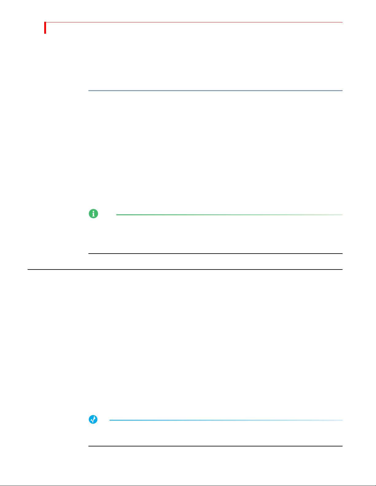
Use to change the CURRENT source
Use to select NEXT source
Use the
CUT buttons to select the CURRENT source. The four buttons labeled A, B, C, and D corre-
spond directly to the Input Source Previews on the Preview Screen (refer to page 36) and to the
MX-4 DV’s four channels. Use the
than an image coming from a source device (refer to “Using Color Backgrounds” on page 42).
When you press any
below the
CUT button glows steadily.
CUT button, the output video cuts to the new source and the indicator light
After selecting the CURRENT source, use the
tons are labeled the same as the
CUT buttons. When you press any NEXT button, the indicator light
above that button flashes.
USING THE VIDEO/AUDIO SELECTOR
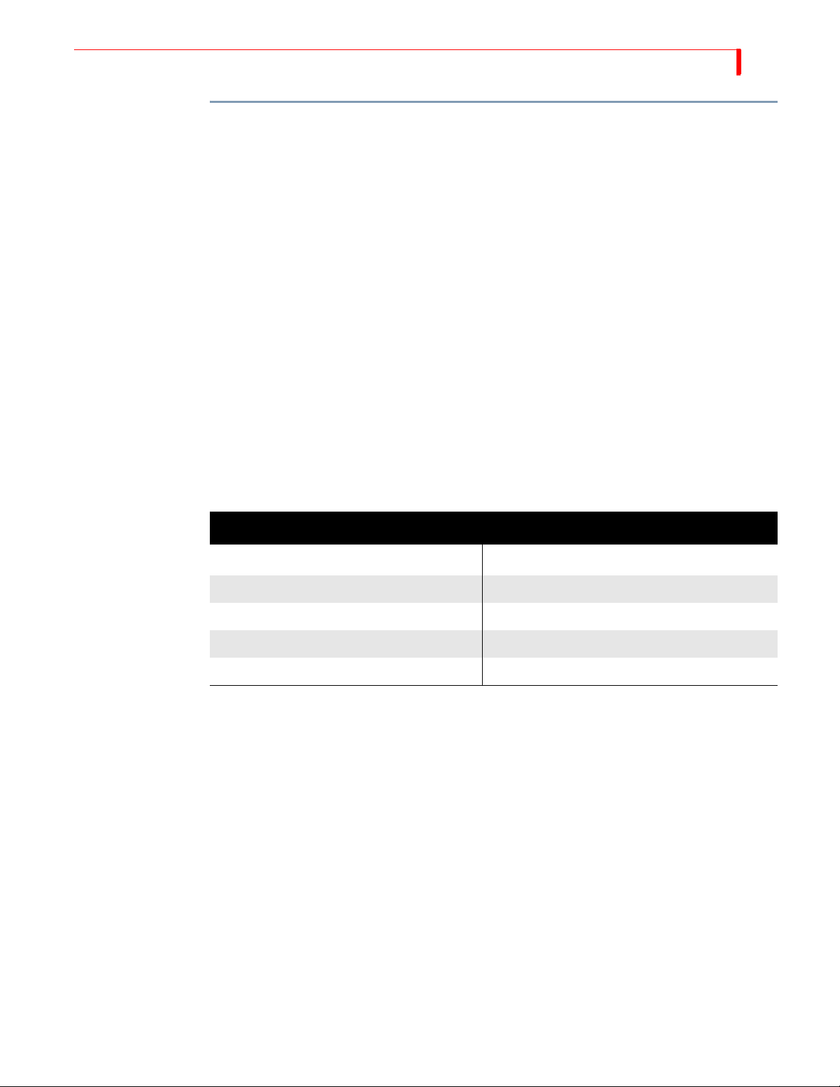
The VIDEO/AUDIO selector controls which parts of the input signal get used from any given source.
You can set the
both. Press the button as required to turn on the Video, Audio, or both lights.
VIDEO – Video changes, audio does not. Video light only is illuminated.
AUDIO – Audio changes, video does not. Audio light only is illuminated.
BOTH – Audio and Video both change. Both the video and audio lights are illuminated.
Many sources (such as pre-recorded video tapes) carry both video and audio signals. Other input
sources (such as a compact disc player) carry only audio signals, and some sources carry only
video signals.
VIDEO/AUDIO selector to any of three positions — VIDEO only, AUDIO only, or
BACKGROUND button to select a solid color background rather
NEXT buttons to select the NEXT source. The but-
Page 44
40
MX-4 DV USER GUIDE CHAPTER 4
Example…
You are producing a documentary on hot air ballooning. You want to over-dub the video
footage of hot air balloons with a narrative audio track. Using the
can process only the video from the VCR and combine it with the audio from an audio tape
containing the voice-over material.
VIDEO/AUDIO selector you
To do this type of mixing:
1 Connect the VCR to one of the MX-4 DV inputs on the rear panel, such as set number one.
2 Connect the audio tape deck to a different set of inputs, such as set number two.
3 Press
4 Press the VIDEO/AUDIO selector until only the VIDEO light is on
5 Press
6 Press the VIDEO/AUDIO selector until only the AUDIO light is on.
7 Press CUT/A to make it the CURRENT source, then press NEXT/B to make it the NEXT source.
8 Start both input devices rolling.
9 Press
NOTE
To designate any part of a signal with the video/audio selector, an input device must be set up
accordingly. For example, to process only the audio signal from a video tape in a VCR, the VCR’s
audio output must be connected to the MX-4 DV’s audio input jacks. Refer to Chapter 3, Installing
the MX-4 DV and also refer to “Route” on page 73.
SWAPPING SOURCES
This section discusses common ways to switch between source devices.
Simple Cuts
CUT/A to select the VCR input.
CUT/B to select the audio deck input.
PLAY to begin outputting the program.
To switch to a specific source, press the CUT button for that source. The CUT buttons cause the
switch to occur almost immediately. For example, press
You don’t need to press
To immediately switch to a colored background, press
the currently selected background color on the output. Set the background color to the color you
want before pressing
for further instructions.
Swapping Between Two Sources
To switch back and forth between two sources, use the PLAY button to automatically switch
between the two.
TIP
When using this back-and-forth switching process, you might find it helpful to use the TWO
CHANNEL mode (SHIFT+2) for the Preview screen. Refer to “Display” beginning on page 69.
CUT/A to immediately switch to that input.
PLAY or use the T-BAR when you use the CUT buttons.
CUT/BACKGROUND. The MX-4 DV displays
CUT/BACKGROUND. Refer to “Working with Colors” beginning on page 41
Page 45
BASIC OPERATIONS WORKING WITH C OLORS
To switch sources using this method:
1 Press the CUT button for the source with which you want to begin — for example, press CUT/A.
2 Press the NEXT button for the other source — for example, press NEXT/B.
41
3 Use the
4 Roll the input sources.
5 To run the transition, press
6 To switch between sources A and B, press
Working with Colors
Common uses for color include solid colored backgrounds and colored borders around objects. So,
you need to know how to choose colors and identify those you’ve chosen.
The MX-4 DV gives each color a unique number ranging from 0 (zero) to 9. The following table
defines these colors and their code numbers.
Table 2: Default Colors and Numbers
CODE COLOR CODE COLOR
0
1 White 6 Bright Blue
ARROW keys to highlight and select a transition, or enter the transition number on the
numeric keypad. Press
OK.
When you need a very quick switch between sources — such as when doing a live broadcast of
two individuals debating — use the Cut transition (zero).
PLAY. At this point, the MX-4 DV switches the sources — source
A becomes the NEXT source, and source B becomes the CURRENT source.
PLAY again.
Black
a
5 Green
2 Gray 7 Light Blue
3 Red 8 Purple
4 Yellow 9 Medium Blue-Green
a. You cannot modify Black (color code 0).
The maximum number of colors in the MX-4 DV palette is ten. You can change nine of the ten colors. You cannot change color 0 (black).
Page 46
42
MX-4 DV USER GUIDE CHAPTER 4
Identifying Colors
Using Color Backgrounds
Colored backgrounds have many uses. For example, to dissolve to a solid black background when
transitioning out of the CURRENT source, hold the black for a moment or two, then dissolve from
the black background into the NEXT source.
TIP
Use the solid color background to lay down ten seconds of black at the beginning of your video.
Transition into and out of solid colored backgrounds basically the same way as transitioning
between sources. The difference is that you must select the background color you want to use
before running the transition.
Background Color
Border Style
Border Color
The Color Selector appears in the upper-right corner of the
Preview screen. It indicates colors selected for the background and borders as well as border style.
The inner-most rectangle shows a sample of color assigned
to the background as well as the color number. The border
around the rectangle shows both the current border style
and color and their associated color and style codes.
To make the selection:
1 Press BG COLOR until the color you want appears in the Color Selector.
2 To immediately cut to the colored background, press CUT/BACKGROUND.
To transition into the colored background, press NEXT/BACKGROUND, then press PLAY or use
T-BAR to switch to the colored background.
the
Changing Colors and Styles
Use the BG COLOR, BORDER COLOR, and BORDER STYLE buttons to change colors and styles. In
each case, press the button repeatedly to cycle through all of the available options for that particular setting.
If you already know the color number of the color you want to assign:
The following sections
describe the
COLOR, BORDER
COLOR, and BORDER
STYLE buttons.
BG
1 Press and hold either BG COLOR or BORDER COLOR, depending on which you want to change.
2 Enter the color number on the numeric keypad. For example, press and hold
BG COLOR, then
press 6 to specify bright blue.
Page 47
BASIC OPERATIONS CREATING C USTOM COLORS
Creating Custom Colors
You can change any color other than color 0 (black) (refer to Table 2 on page 41) to create custom
colors. You cannot add more colors, but you can change the existing ones. Once you create a custom color, it stays permanently in the MX-4 DV unit until and unless you change it again.
BG COLOR and BORDER COLOR share the color palette. Therefore, changing any color affects both
the background and border colors.
To create a custom color:
1 Press BG COLOR or BORDER COLOR until the color you want to change appears in the Color
Selector.
43
2 Press
LEARN+BG COLOR or LEARN+BORDER COLOR (depending on which one you want to
change).
These key combinations activate Learn Color mode. The MX-4 DV blinks the
selector lights to indicate you are in the proper mode.
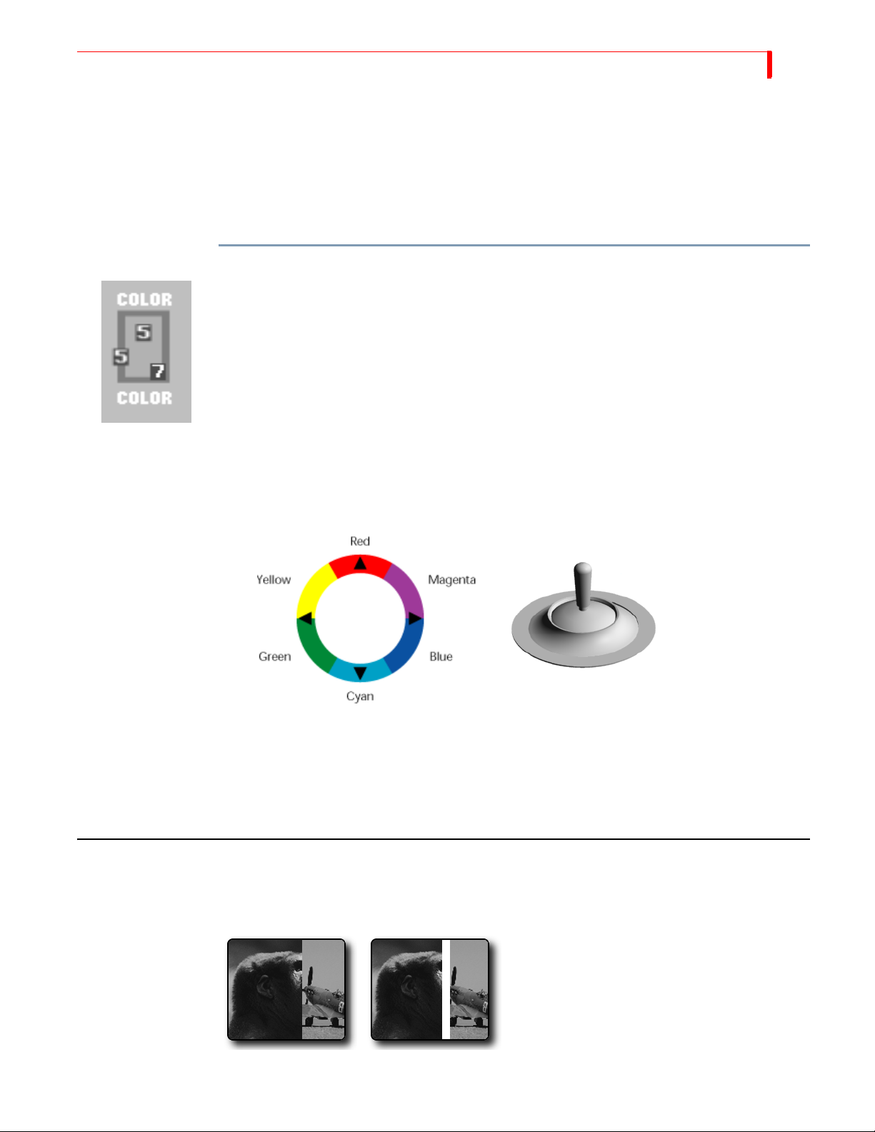
3 Use the
aMove the
JOYSTICK and T-BAR in combination to define the new color.
T-BAR up and down its slot to adjust luminance.
b You can use the SHIFT+ARROW KEYS for fine adjustment to luminance.
c Move the JOYSTICK relative to its color ring to adjust chrominance (or color value).
d You can use the arrow keys for fine adjustments to chrominance.
4 When the color you want appears in the Color Selector, press
mode and the
VIDEO/AUDIO lights cease blinking.
If you decide you don’t want to change the color after manipulating the
SHIFT+0 (zero) to revert back to the original color. The MX-4 DV restores the original
press
color and exits from Learn Color mode (the
VIDEO/AUDIO lights cease blinking).
OK. You exit from Learn Color
JOYSTICK and T-BAR,
VIDEO/AUDIO
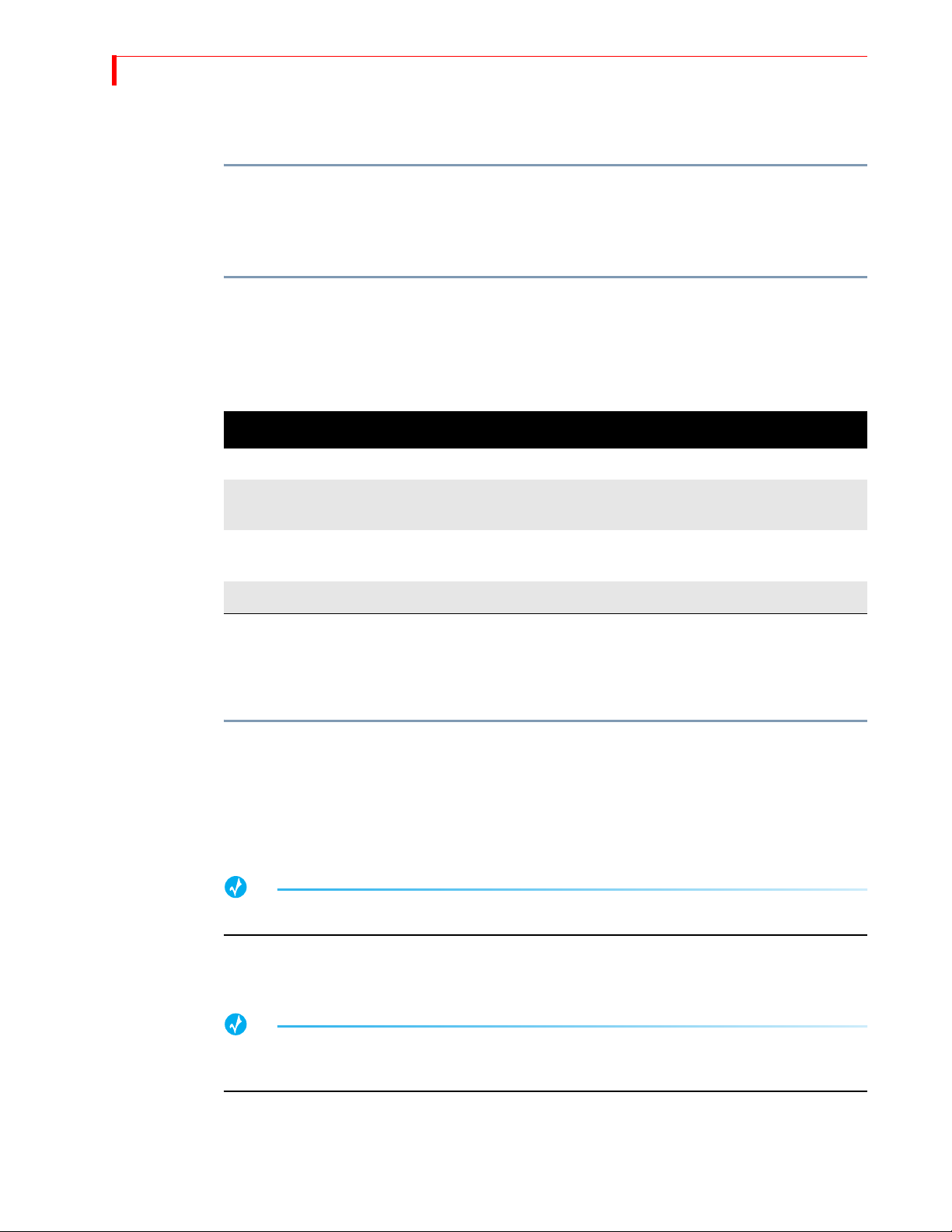
USING BORDERS
Borders have many uses, such as providing a distinct separation between two sources while running a transition.
Wipe Transition
No Border
Wipe Transition
White Border
Page 48
44
MX-4 DV USER GUIDE CHAPTER 4
You can also use borders to frame images in a picture-in-picture (PIP) image, and so forth. Whatever purpose you use a border for, you can specify the color and style for the border.
To specify border color:
• Repeatedly press
BORDER COLOR to cycle through the available colors. The Color Selector
shows the current color.
BORDER STYLE+0 (zero) to immediately turn off the border.
Press
To specify border style:
• Repeatedly press
BORDER STYLE to cycle through the available styles. The Border Style indi-
cator in the Color Selector increments by one each time you press the button. You can specify
ten different styles (0 through 9).
Table 3: Border Styles (Defaults)
NO. RESULT NOTES
0 Border and Edges Off
1-3 Soft Edge Border
4-6 Colored Border
7-9 Drop Shadow Border
Changing Border Styles
This section explains how to specify different edges, color borders, and drop shadows to use in
conjunction with border styles.
To change a border style setting
1 While the Preview screen is displayed, enter
to 9 (inclusive) and is the number of the border style you want to change, as shown in the preceding table.
2 Select the shape or edge to which you want to add a border or shadow by selecting an appro-
priate transition.
TIP
Try using transitions 300-305 for edges and 554-562 for shapes.
Use LEARN+UP/DOWN ARROW keys to soften and harden border edges.
LEARN+RIGHT/LEFT ARROW keys adjust border width.
LEARN+UP/DOWN ARROW keys soften the border.
LEARN+ARROW keys reposition drop shadow.
BORDER STYLE+# — where # can range from 1
3 Move the T-BAR to its mid point.
4 Press
LEARN+BORDER STYLE to cycle between soft edge, color border or drop shadow.
TIP
Make note of the border style number you are changing for future reference.
You can also use PIP to select and modify border styles for shapes.
5 Use LEARN+ARROW KEYS (as indicated in Table 4, “Keys for Changing Border Attributes,”
on page 45, below) to specify what you want to change – width, softness, or position.
6 Return the
T-BAR to its full up or full down position.
Page 49

BASIC OPERATIONS CHANGING BORDER S TYLES
The MX-4 DV automatically stores the border style so that it is available until and unless you
change it again.
Table 4: Keys for Changing Border Attributes
FUNCTION KEY COMBINATION
45
Toggle through Soft Edges, Color Border,
and Drop Shadow
Soft Edges
Increase Softness
Decrease Softness
Color Border
Increase border thickness
Decrease border thickness
Increase border softness
Decrease border softness
Drop Shadow
a
Move shadow right
Move shadow left
Move shadow up
Move shadow down
LEARN+BORDER STYLE
LEARN+UP ARROW
LEARN+DOWN ARROW
LEARN+RIGHT ARROW
LEARN+LEFT ARROW
LEARN+UP ARROW
LEARN+DOWN ARROW
LEARN+RIGHT ARROW
LEARN+LEFT ARROW
LEARN+UP ARROW
LEARN+DOWN ARROW
a. Drop Shadows created for edges do not translate well to shapes, and vice-versa. Therefore, you should
specify one set of drop shadow styles for shapes and another for edges.
Page 50

NOTES
Page 51
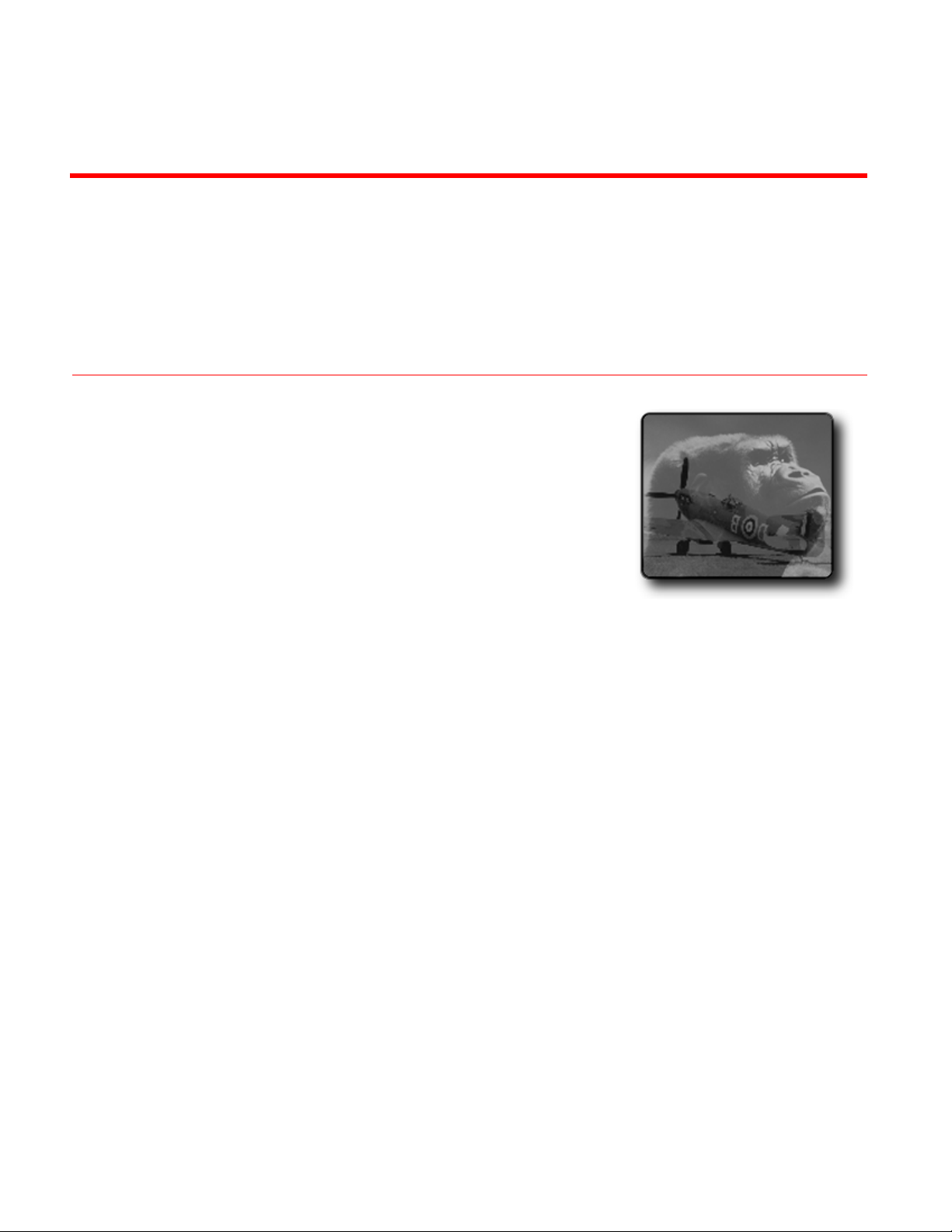
CHAPTER 5
TRANSITIONS
The MX-4 DV contains over 700 transitions from which you can choose. Furthermore, you
can manually control any transition to change the way it works, thereby creating your own
versions of the supplied set.
Transitions artistically switch from one scene to the next in a production. The MX-4 DV
transitions range from simple cuts, dissolves, and wipes to sophisticated zooms, fly-ins, and
flips. You can change the speed (either manually or automatically) at which transitions run,
and run them in reverse. Combine these features for many different variations.
In this chapter you’ll learn about:
• Basic transition concepts – what is a transition and how to use it
• Transition Categories and Menus
• Selecting Sources to use during Transitions
• Selecting Transitions
• Adjusting Transitions
• Running Transitions
Page 52
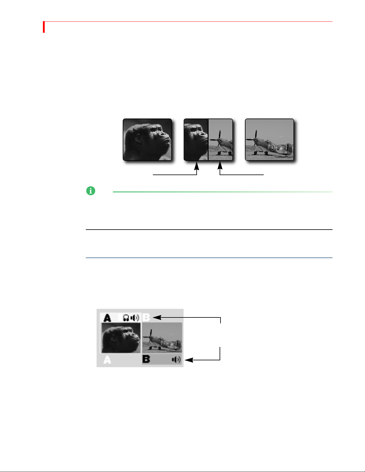
48
MX-4 DV USER GUIDE CHAPTER 5
BASIC TRANSITION CONCEPTS
Transitions create on-screen effects used when switching from one source to another (that is, one
scene to another). The most basic type of transition is the cut, where the first frame from the NEXT
source immediately replaces the last frame from the CURRENT source. Cuts produce abrupt
changes. Other types of transitions use special effects to produce a smoother, more artistic change
from one source to the next. The following illustration shows a horizontal wipe transition.
CURRENT NEXT
NOTE
When discussing transitions, we use the letters a and b to differentiate the beginning scene (a) from
the ending scene (b). These letters often appear in the transition icons to indicate the direction in
which the transition travels. These letter indicators have no relationship to the A, B, C, and D
letters used to differentiate between the MX-4 DV channels.
Transition
in Progress
ab
The following basic steps explain how to run a transition with the MX-4 DV. Each step is
described in more detail later in this chapter.
To run a transition:
1 Display the CURRENT source on the output screen. For example, press CUT/A to make A the
current source.
2 Select the NEXT source — the one you want to appear on the output following the transition.
For example, press
3 Select a transition to use. For example, press the
NEXT/B to make that the next source.
Highlights above and below the source previews
indicate CURRENT and NEXT sources, respectively.
BASIC Transition Category button, then select
a wipe transition from the menu.
4 Prepare the sources (such as VCRs and camcorders) and let them roll.
5 At the right moment, use either the
T-BAR or the PLAY button to run the transition.
As you can see, you first set up the transition, then execute it. Nothing happens until you use the
T-BAR or PLAY button to run the transition. So, you set everything up, then run the transition at the
precise moment you want it to occur. As soon as one transition finishes, immediately set up the
next one so that all you have to do is press
PLAY or use the T-BAR to proceed.
Page 53
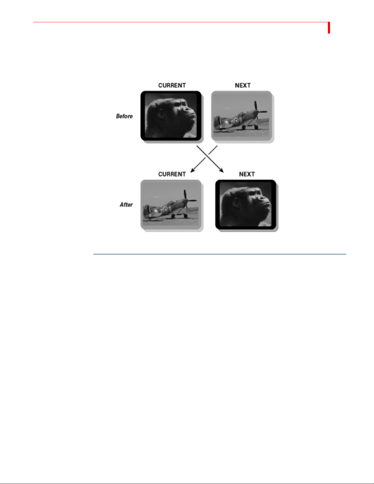
TRANSITIONS BASIC TRANSITION CONCEPTS
You can select the CURRENT source, the NEXT source, and the transition in any order, and
change them as many times as necessary before actually running the transition.
At the completion of the transition, the CURRENT and NEXT sources swap places — that is,
CURRENT becomes NEXT, and NEXT becomes CURRENT.
49
At this point, you can do one of the following:
• Leave the CURRENT and NEXT sources as they are and switch back and forth between them;
or,
• Select a new NEXT source and, optionally, a new transition, then repeat the process.
Page 54
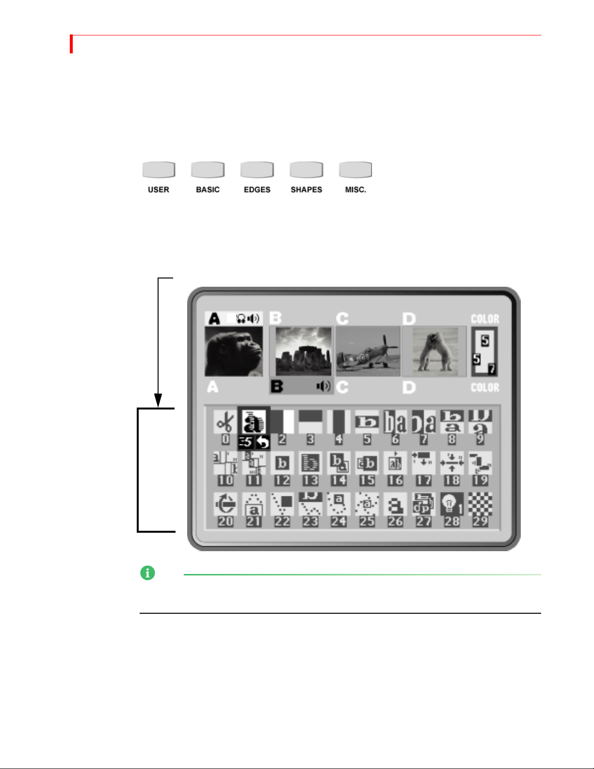
50
MX-4 DV USER GUIDE CHAPTER 5
TRANSITION CATEGORIES AND MENUS
To help manage the 700+ transitions, the MX-4 DV separates them into five logical categories —
User, Basic, Edges, Shapes, and Misc. Use the Transition Category buttons to access the different
categories.
Transition Category Buttons
When you press a Transition Category button, MX-4 DV displays the transitions available in that
category in the Transitions Menu. The content of the menu differs depending on which category
you select. However, the menus have a common structure and always appear in the same place.
The content of the Transitions Menu differs depending on the Category selected.
Transitions
Menu
NOTE
The Transitions Menu does not appear when you work with the Full, Current, or Next Preview
screen. Refer to “Display” beginning on page 69 for more information.
Use the ARROW keys to navigate the Transitions Menu. If the category contains more transitions
than can appear in the menu at one time, use the
UP and DOWN ARROW keys to scroll through
them. You can scroll through only those transitions in the current category.
Page 55

TRANSITIONS BASIC TRANSITIONS CATEGORY
The MX-4 DV color codes the transition icons in the menu:
Basic White
Edges Blue
Misc. Yellow
Shapes Red
Basic Transitions Category
This category includes common transitions, such as wipes and dissolves. The transitions in this category are color coded white. Refer to page 136 for samples.
51
MXProDV
Compatibility
If you are upgrading to the MX-4 DV from the Videonics MXProDV Video Mixer, the transitions
in the basic category are the same as the MXProDV except for 60 new transitions.
The MX-4 DV provides a set of hot keys that directly correspond to the MX-4 DV buttons. Using
the hot keys (in the following table) causes the MX-4 DV Preview screen cursor to appear at the
beginning of each section within the basic category.
Table 5: MX-4 DV Compatibility Hot Keys
FUNCTION MX-4 HOT KEY
Fades and Dissolves
Wipes
Zooms
Flips
Edges Transitions Category
These transitions move a curved or jagged edge across the screen when transitioning to a different
picture source. Transitions in this category are color coded blue. Refer to page 144 for samples.
Misc. Transitions Category
SHIFT+BASIC
SHIFT+EDGES
SHIFT+MISC.
SHIFT+SHAPES
The transitions in this category move cutout and compression images across the screen as a change
occurs. The cutout images and compression images go away once the transition finishes. Transitions in this category are color coded yellow. Refer to page 145 for samples.
Shapes Transitions Category
These transitions occur as a wipe in the shape of a geometric object, such as a heart, a five-pointed
star, and so forth. Transitions are color coded red. Refer to page 146.
User Transitions Category
It’s unlikely you’ll use all of the available transitions — but it is likely that you’ll have a limited set
you use most of the time. With this in mind, the MX-4 DV makes it easy for you to access your
favorite transitions by creating your own personal menu — the User menu. The MX-4 DV comes
with a default set, but you can change them to tailor the User menu to your preferences and needs.
Page 56

52
MX-4 DV USER GUIDE CHAPTER 5
TIP
During production planning, determine which transitions you want to use, then set up the User
category to contain those transitions. This gives you quick, immediate access to the transitions
without having to search through the other categories. See the following section (“Changing User
Transitions Menu”) to learn how to tailor the menu to your preferences.
CHANGING USER TRANSITIONS MENU
The first time you power up the MX-4 DV and press the USER Transitions Category button, the
default transitions appear in the menu. The default set contains a variety of transitions from the
other four categories, as defined by FOCUS Enhancements at the factory. If you are satisfied with
the default set, there is no need to change them.
USER category does not contain distinct transitions – that is, all transitions in the USER
The
category actually exist in other categories (basic, edges, shapes, and misc.). Think of the
category as a collection of references to other transitions.
USER
Restoring Default
User Transitions
You can change as many transitions in the
USER menu as you want.
To change a transition in the User menu:
1 Decide which transition you want to add to the
USER category. Refer to Appendix A, Transi -
tions List, for a list of valid numbers and their associated transitions.
2 If necessary, press
DISPLAY to set the Preview screen to Standard or Two Channel mode.
In the other Preview modes (Full, Current, or Next), the MX-4 DV does not display the Transitions Menu. Refer to “Display” beginning on page 73.
3 Press the
4 Use the
USER Transition Category button to display the menu on the Preview screen.
ARROW keys to highlight the transition you want to replace in the USER category.
5 Enter the number of the transition you selected in step 1, above. You can enter the number of
any transition from any category.
6 Press
You can easily restore the default set of transitions in the User category. NOTE: By pressing #+
OK.
OK
you can also set a transition in the User menu.
To restore the default set of transition to the User menu:
1 If necessary, press the
USER Transition Category button to display that menu on the Preview
screen.
2 Enter
SHIFT+0 (zero). This restores the default set of transitions for this category.
Page 57
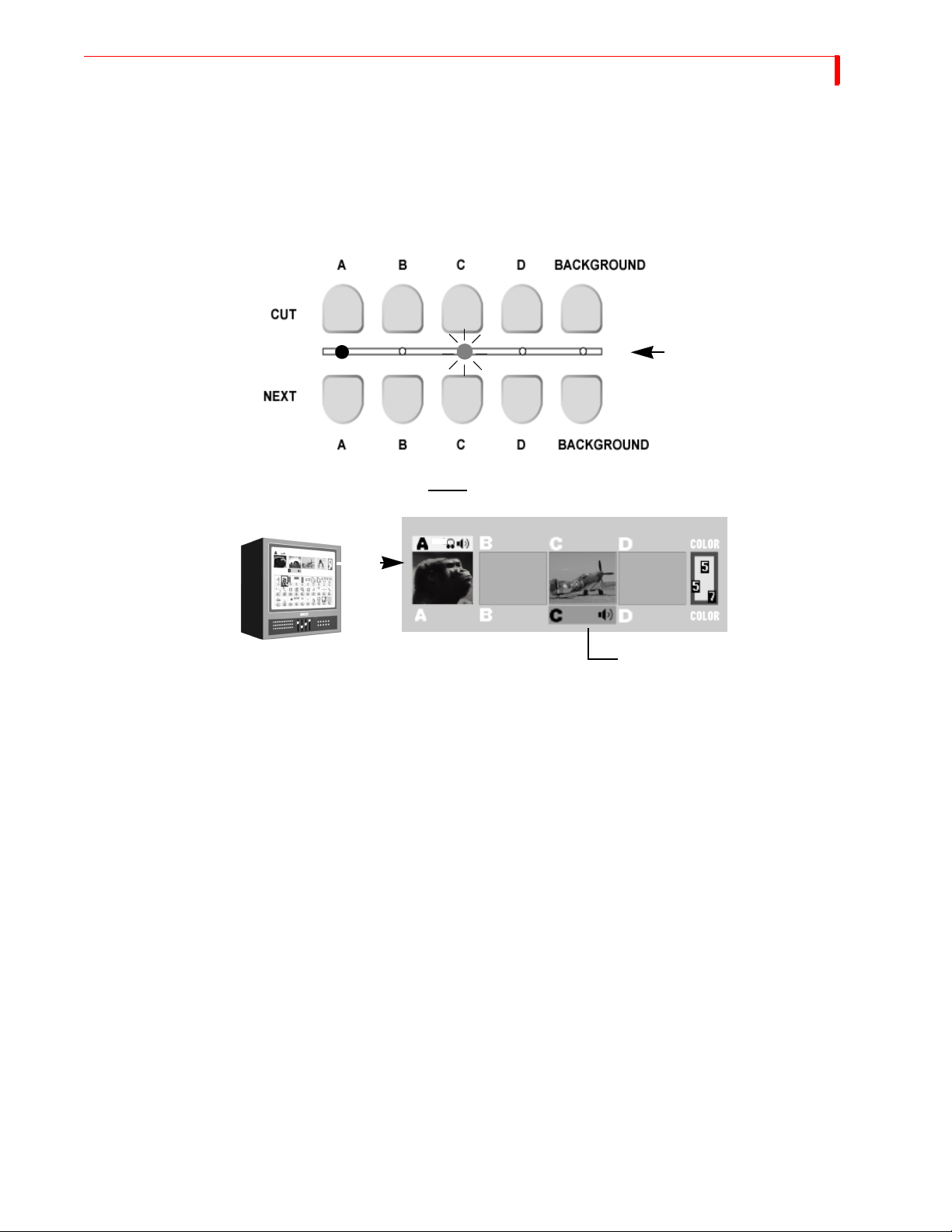
TRANSITIONS SELECTING TRANSITION SOURCES
SELECTING TRANSITION SOURCES
An important step in setting up a transition is to identify the CURRENT and NEXT sources. Use
CUT and NEXT to choose the two sources. The MX-4 DV provides feedback in a couple of different ways to confirm your choices.
Selecting Sources and Getting Feedback
The lights between the rows of
CUT and NEXT buttons act as
indicators. A steady light identifies
the CURRENT source (A) – a
flashing light identifies the NEXT
source (C).
Yellow highlights the CURRENT source (A)
53
The MX-4 DV identifies the CURRENT source by a yellow highlight on the Preview screen and a
steady light beneath the corresponding
highlight on the Preview screen and a flashing light above the corresponding
If you make CURRENT and NEXT the same source, the source light (between the two rows of
buttons) flashes as though it were just the NEXT source.
Setting the CURRENT Source
In many cases you don’t need to select the CURRENT source because the ending source from the
previous transition automatically becomes the new CURRENT source (refer to the diagram on
page 49). However, if you want to change the CURRENT source, press the corresponding cut button. For example, pressing
immediately displays D’s signal.
Setting the NEXT Source
To specify the NEXT source, press the corresponding NEXT button. For example, to make D the
next source, press
Green highlights the NEXT source (C)
CUT button. It identifies the NEXT source by a green
NEXT button.
CUT/D makes D the CURRENT source, and the Program monitor
NEXT/D.
Page 58
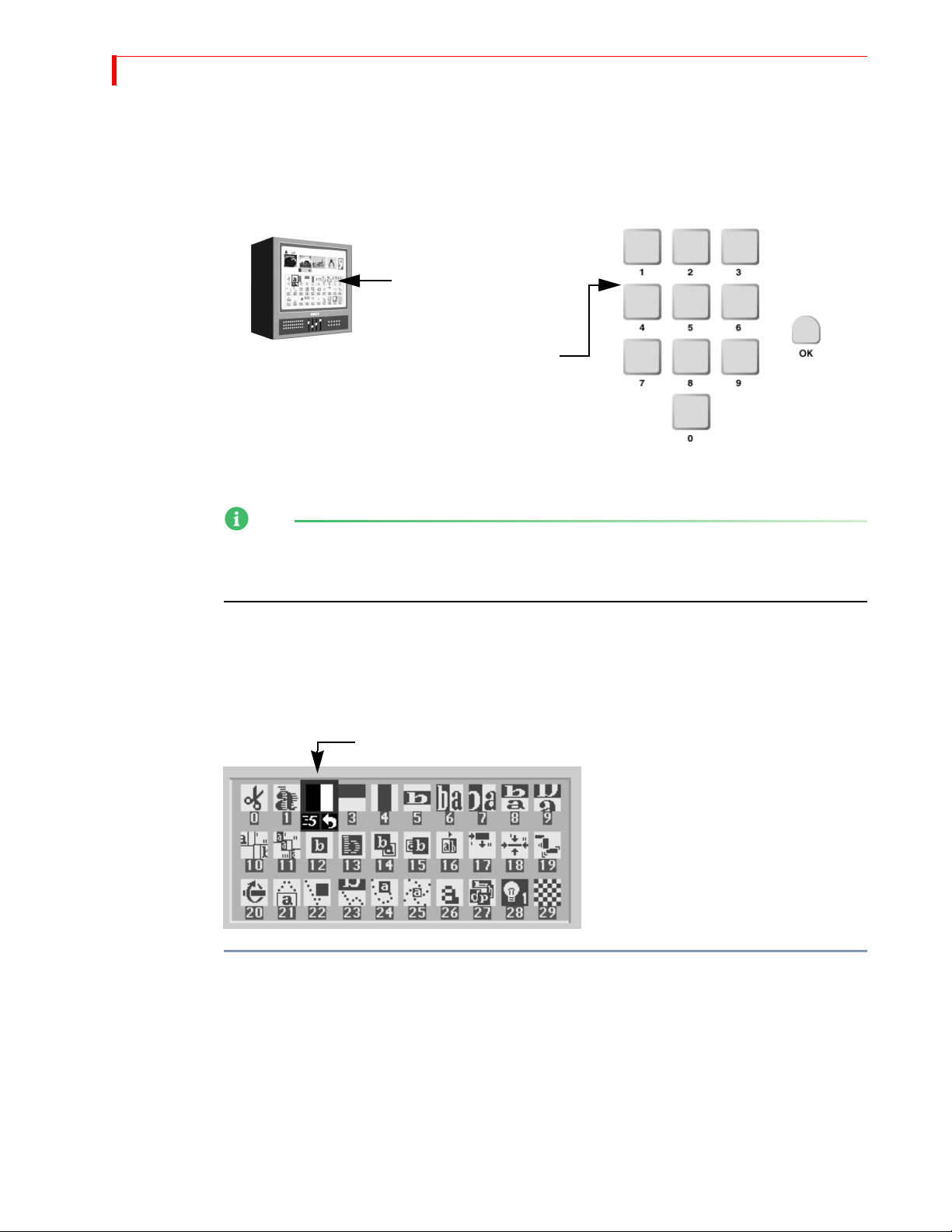
54
MX-4 DV USER GUIDE CHAPTER 5
SELECTING TRANSITIONS
To select a transition to use between the CURRENT and NEXT sources, do one of the following:
•Use the
• Enter the transition’s assigned number on the MX-4 DV numeric keypad, then press
NOTE
When selecting from the user category, you must always use the arrow keys to select a transition
from the Transition Menu on the Preview screen. Entering a transition number and pressing ok
replaces the current transition with the one you select.
ARROW keys to select from the Transitions Menu on the Preview screen; or,
Preview
Screen
Use ARROW keys to select a
transition from the Transition
Menu on the Preview
Screen…
or
…enter the transition number
on the keypad…
then press
OK.
OK.
…
Numeric
Keypad
Using the Transitions Menu
The Transitions menu appears just below the preview images on the Preview screen when you set
the Preview to Standard or Two Channel mode (refer to “Display” beginning on page 69 for more
information about Preview modes).
To select a transition from the Transitions Menu:
1 If necessary, press the appropriate Transition Category button to display the set of transitions
containing the one you want.
2 Use the
Blue highlights the currently selected transition. Use the
the highlight horizontally. Use the
When you reach the bottom row of icons in the current menu, press
additional transitions in the category, if present.
Blue highlights the selected transition
Each icon in the
menu represents
one transition.
ARROW keys to highlight the transition you want to use.
LEFT and RIGHT ARROWS to move
UP and DOWN ARROWS to move the highlight vertically.
DOWN arrow to display
Page 59
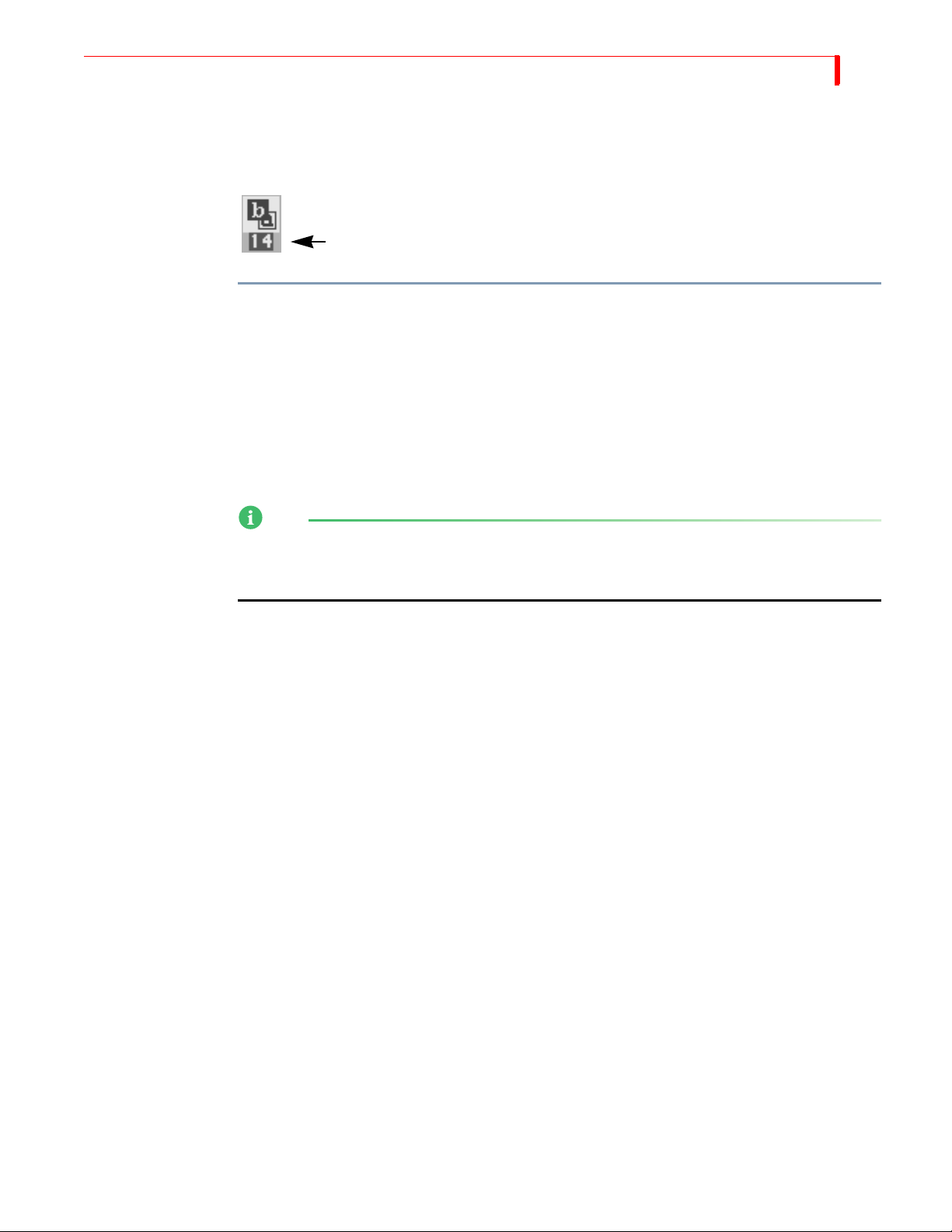
TRANSITIONS USING TRANSITION NUMBERS
Using Transition Numbers
Every transition has a number assigned for reference and identification. The number appears in the
Transitions Menu just below each transition icon.
The transition number…
in this example, number 14
To select a transition using transition numbers:
1 Enter the transition number on the keyboard.
55
2 Press
OK.
To immediately play back the transition, press
PLAY rather than OK.
Refer to Appendix A, Transitions List, for a complete listing of transitions and their assigned numbers.
If you make a mistake entering a number, press
OK, enter the number correctly, then press OK
again.
NOTE
When you highlight a transition in a Transitions menu, the highlighting obscures the transition
number. The number below the transition icon represents the speed at which the transition plays.
The following section, “Adjusting Transitions” discusses this.
Page 60
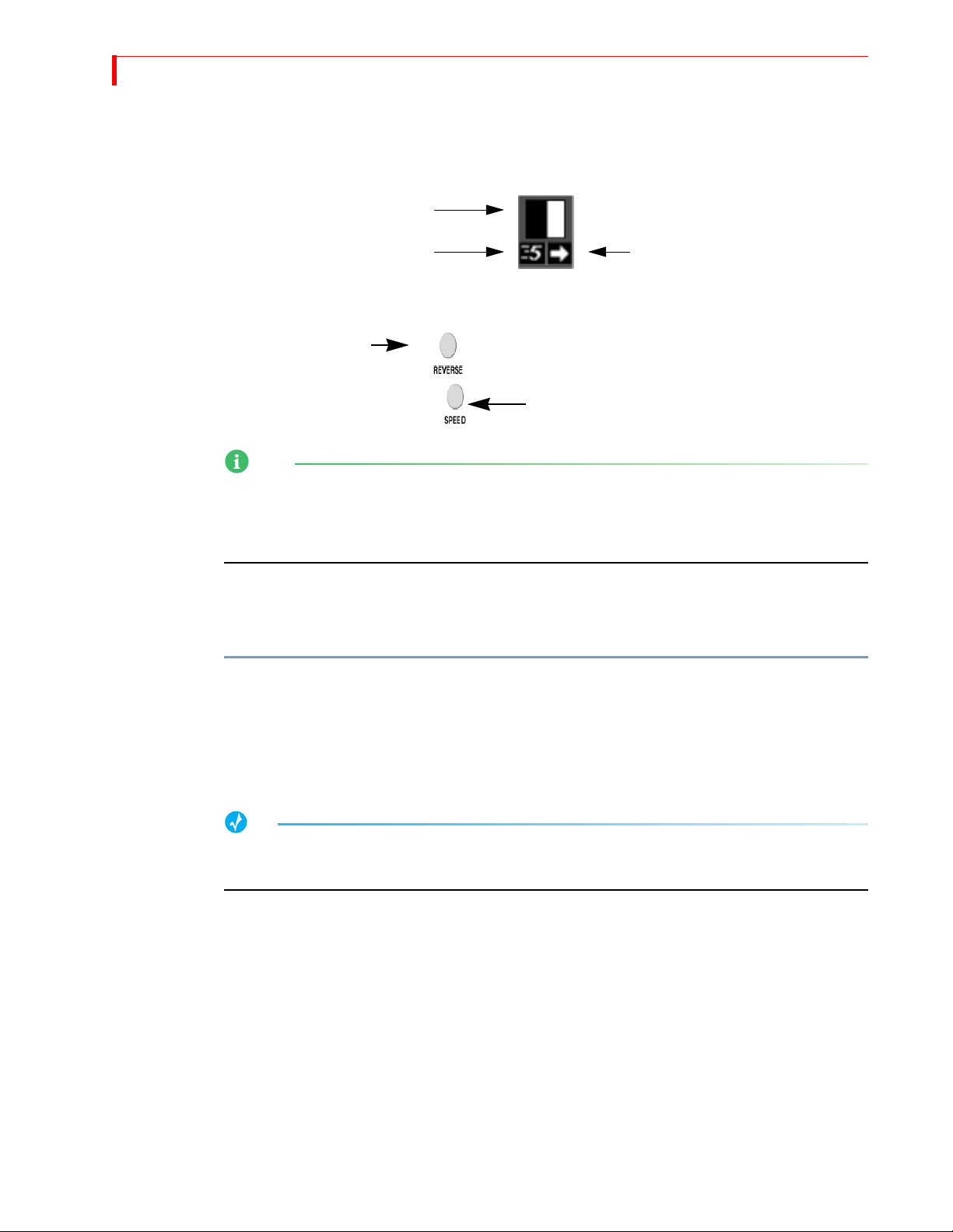
56
MX-4 DV USER GUIDE CHAPTER 5
ADJUSTING TRANSITIONS
Every transition runs at a pre-set speed and direction. Symbols appear below the transition icon in
the Transitions Menu indicating the current speed and direction.
Transition Icon
Use the
Transition Direction
SPEED and REVERSE buttons to change the speed and/or direction of a transition.
NOTE
When you change a transition’s speed and/or direction, the change applies to all other transitions
until you specifically change it. For example, if you set the speed of the current transition to 4, all
subsequent transitions run at this same speed until you again change the speed factor. This also
applies to transition direction.
Changing Transition Speed
Transition speed values can range from 0 (slowest) to 9 (fastest).
To change the transition’s speed:
• Press
SPEED. Each press increases the speed by one unit. Press SHIFT+SPEED to decrease the
speed by one unit.
Transition Speed
Transition Direction
Transition Speed
The MX-4 DV changes the Transition Speed indicator below the transition icon to the currently
selected value. You can change the speed any time either prior to running the transition, or while it
runs (which allows you to make adjustments “on the fly.”)
TIP
To directly set the speed to a specific value, press and hold the SPEED button while entering a value
from 0 to 9 on the numeric keypad.
Changing Transition Direction
Transitions can run in two directions — forward and reverse. If you use the PLAY button, transitions run, by default, in the forward direction. If you use the
forward; moving it down runs it in reverse. For example, a simple wipe transition might move a
vertical border across the screen from right-to-left or left-to-right, replacing scene a with scene b.
Example…
Suppose you’re producing a video showing renovations to a building. Occasionally you want
to go back and show how the building looked originally. When going back in time, use a wipe
transition that moves from left-to-right. When going forward in time (to show the new
modifications), reverse the wipe so that it moves from right-to-left.
T-BAR, moving it up runs the transition
Page 61
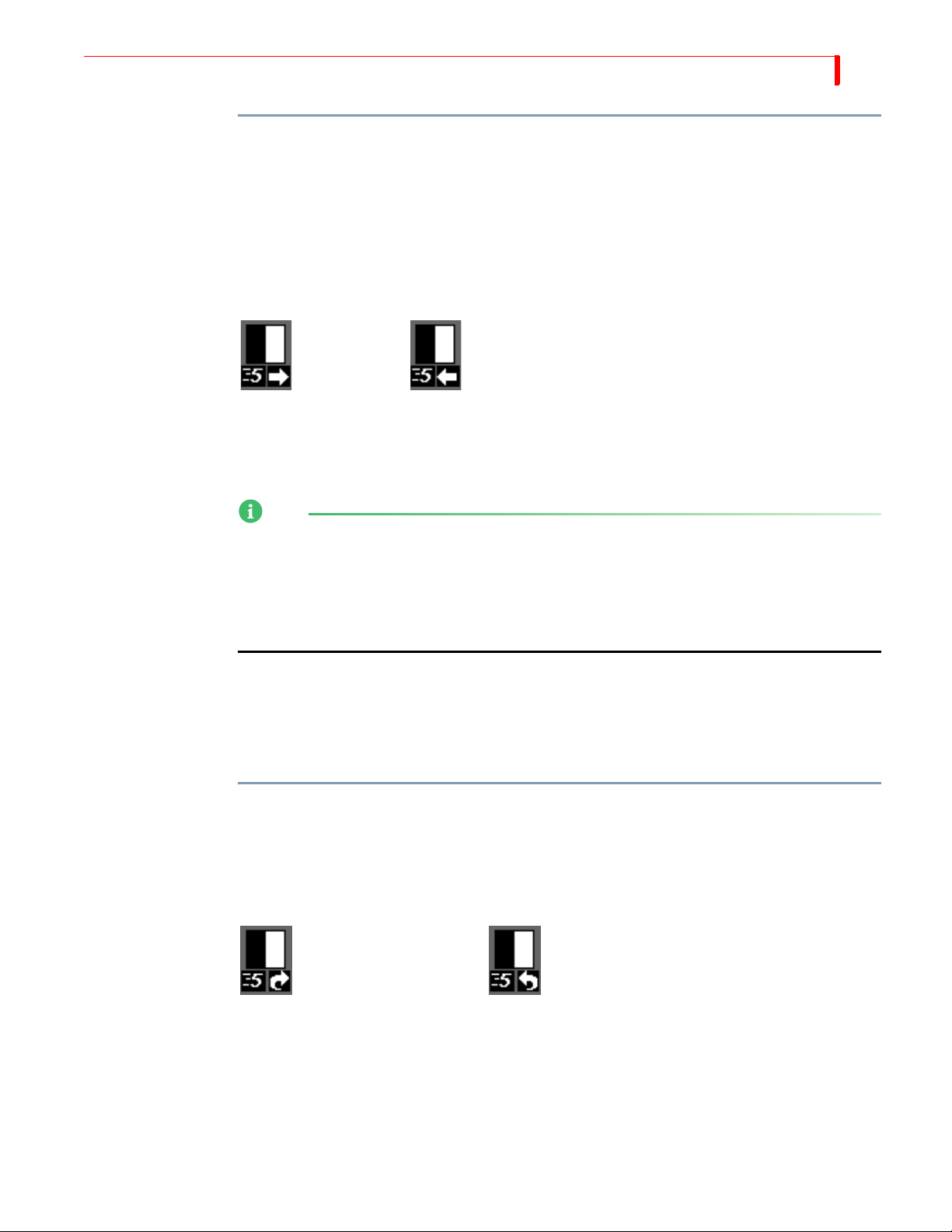
TRANSITIONS CHANGING T RANSITION DIRECTION
To reverse a transition:
• Press
REVERSE.
Remember, all transitions run in reverse until you press
REVERSE again. Reverse has no effect
on a simple Cut or Dissolve transition because reversing those transitions produces no visible
result.
MX-4 DV changes the Transition Direction indicator below the transition icon to the currently
selected direction. When the arrow points right, the transition runs in its normal direction. When
the arrow points left, the transition runs in reverse.
Forward Reverse
The Reverse function does not change the relationship between the sources. For example, a vertical
wipe from source A to B moves from the top of the screen to the bottom, replacing source A with
B. If you apply the Reverse function, source B still replaces A, but the transition wipes from the
bottom of the screen to the top.
NOTE
Mosaic, dissolve, and misc. transitions work in only one direction at all times, including when you
FREEZE before running the transition.
press
57
Using
Auto-Reverse
You cannot run Misc.-type transitions in a reverse direction. If you select a Misc.-type transition,
then move the
T-BAR from its up position to the down position, the MX-4 DV performs a simple
dissolve (transition 160).
Auto-Reverse automatically reverses the direction of transitions each time they run. In the previous
building renovation example, you press
REVERSE at the conclusion of each transition to alternate
between left-to-right and right-to-left wipes. When you use Auto-Reverse, the MX-4 DV handles
switching automatically. For example, if the transition is set to run from left-to-right, it automatically alternates between left-to-right and right-to-left each time it runs.
To invoke the Auto-Reverse feature:
•Enter
SHIFT+REVERSE.
With Auto-Reverse activated, the MX-4 DV displays a distinct arrow below the transition’s icon in
the Transitions Menu. To manually reverse the current direction even with Auto-Reverse activated,
REVERSE at any time.
press
Auto-Reverse Forward Auto-Reverse Backward
Auto-Reverse remains active until you press
SHIFT+REVERSE again to go back to one-way transi-
tions. Auto-Reverse has no effect on dissolve and Misc. transitions.
Page 62
58
MX-4 DV USER GUIDE CHAPTER 5
RUNNING TRANSITIONS
After selecting the CURRENT and NEXT sources and the transition to use, you can run the transition either automatically or manually.
•Use PLAY to run transitions automatically, when you want them to run smoothly and always
the same way.
•Use the
For example, you can make the transition speed up, slow down, or even reverse itself at any
point.
NOTE
If you apply the strobe effect to a source, the MX-4 DV automatically turns it off while the
transition runs (refer to “Strobe” on page 69).
Running a Misc.-type transition to either the Background channel or a channel with no video source
executes a simple dissolve (transition 160).
Running Transitions Automatically
T-BAR to run transitions manually, when you want fine control over the way it runs.
To run a transition automatically at a predetermined speed:
• Press
PLAY.
You can pause an automatic transition by pressing
transition alternately stops and starts until you finally allow it to finish. Although the transition
pauses, the video continues to play.
Running Transitions Manually
Use the T-BAR to manually control transitions. You can change a transition’s speed and reverse its
direction.
Operating the
T-BAR
The
T-BAR operates as follows:
•Moving the
•Moving the
• Holding down the
method to reposition the
PLAY again. Each time you press the button, the
T-BAR from the DOWN to UP position runs the transition forward.
T-BAR from the UP to DOWN position runs the transition in reverse.
SHIFT button while moving the T-BAR disables T-BAR operation. Use this
T-BAR without running a transition or effect.
Page 63
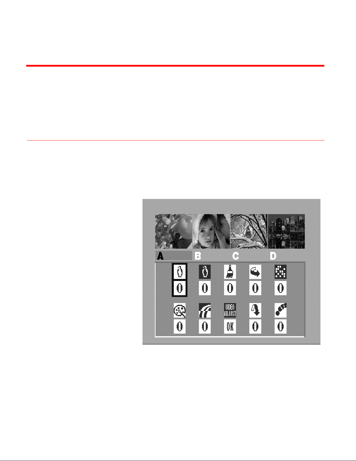
CHAPTER 6
INPUT EFFECTS
This chapter describes MX-4 DV Input Effects, that are available in the following button
group on the MX-4 DV keyboard.
Use Input Effects in the following ways:
• Apply input effects to any source.
• Combine many different input effects to create entirely new effects.
• Apply input effects to some, none, or all sources, in any combination.
• With miscellaneous transitions.
• With multi-PIPs.
• In compose mode.
Page 64
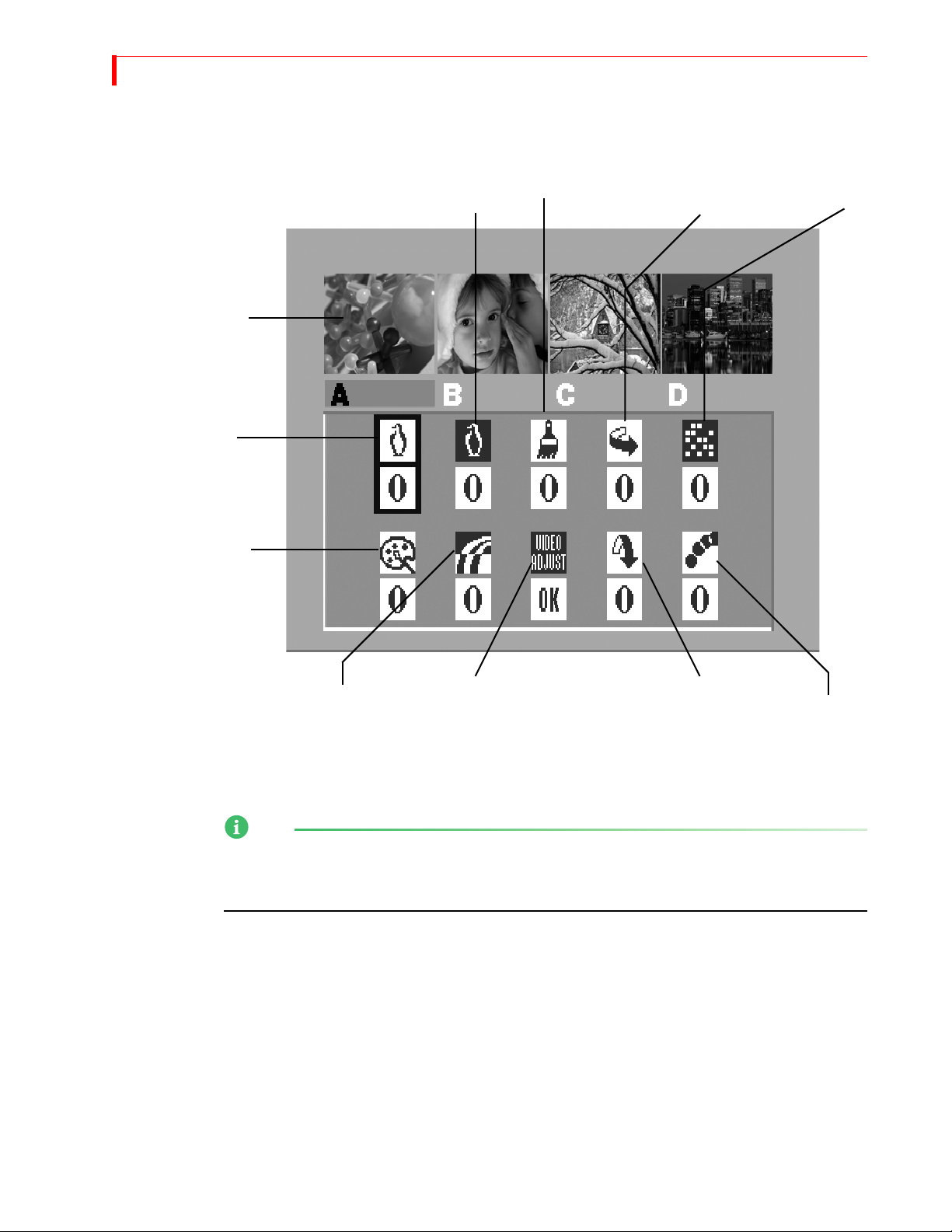
60
MX-4 DV USER GUIDE CHAPTER 6
INPUT EFFECTS MENU
Press any input effects button to display the Input Effects Menu — or, press the EFFECTS button.
MX-4 DV updates the
preview images to show
Input Effects.
B&W
B&W
NEGATIVE
POSTERIZE
FLIP
HORIZONTAL
MOSAIC
COLOR
CORRECT
When you press one of the input effects buttons (such as
selects that effect in the menu. When you press the
the first item in the menu —
COLOR
NEGATIVE
NOTE
The menu does not contain an icon or settings for the chromakey option. When you press the
CHROMAKEY button, the MX-4 DV takes you directly to the chromakey screen. Refer to Chapter
10, Chromakey, for details.
VIDEO
ADJUSTMENT
POSTERIZE), the MX-4 DV automatically
INPUT EFFECTS button, the MX-4 DV selects
B&W.
FLIP
VERTICAL
STROBE
Page 65

INPUT EFFECTS SPECIAL KEY COMBINATIONS
Special Key Combinations
Use the following key combinations while working with the Input Effects menu.
Table 6: Input Effects Mode Key Combinations
KEY COMBINATION RESULT
61
ARROW keys
Moves cursor (or, highlight) between the different Input Effects.
Numeric Keypad Directly sets the parameter value for the highlighted effect.
EFFECTS or OK
EFFECTS buttons Moves the cursor directly to that effect – for example, press POS-
Exits from Input Effects mode.
TERIZE to highlight that effect: press MOSAIC to highlight that
effect: and so on.
If the selected effect matches the currently highlighted one on the
Input Effects menu, pressing the
EFFECTS button increments the
effect’s parameter value by one.
SHIFT+0 (zero)
Resets all effects to 0 (off) for the selected channel.
When you are not working at the Input Effects menu, use the following key combinations.
Table 7: Main Mode Input Effects Key Combinations
KEY COMBINATION RESULT
SHIFT+EFFECTS button
Increments the parameter value by one for the selected effect and
applies it to the CURRENT source.
SHIFT+EFFECTS
Temporarily disables and re-enables Input Effects from being
sent to Program out. Refer to the following paragraph.
When the Effects LED light is lit, Input Effects are enabled. The MX-4 DV applies the effects
according to the parameter values for each effect.
When you use the
SHIFT+EFFECTS key combination to disable Input Effects, the MX-4 DV turns
off the LED light. It does not change any effects parameter values, but it does prevent the current
Input Effects from being used. Press
SHIFT+EFFECTS again to enable them.
Page 66
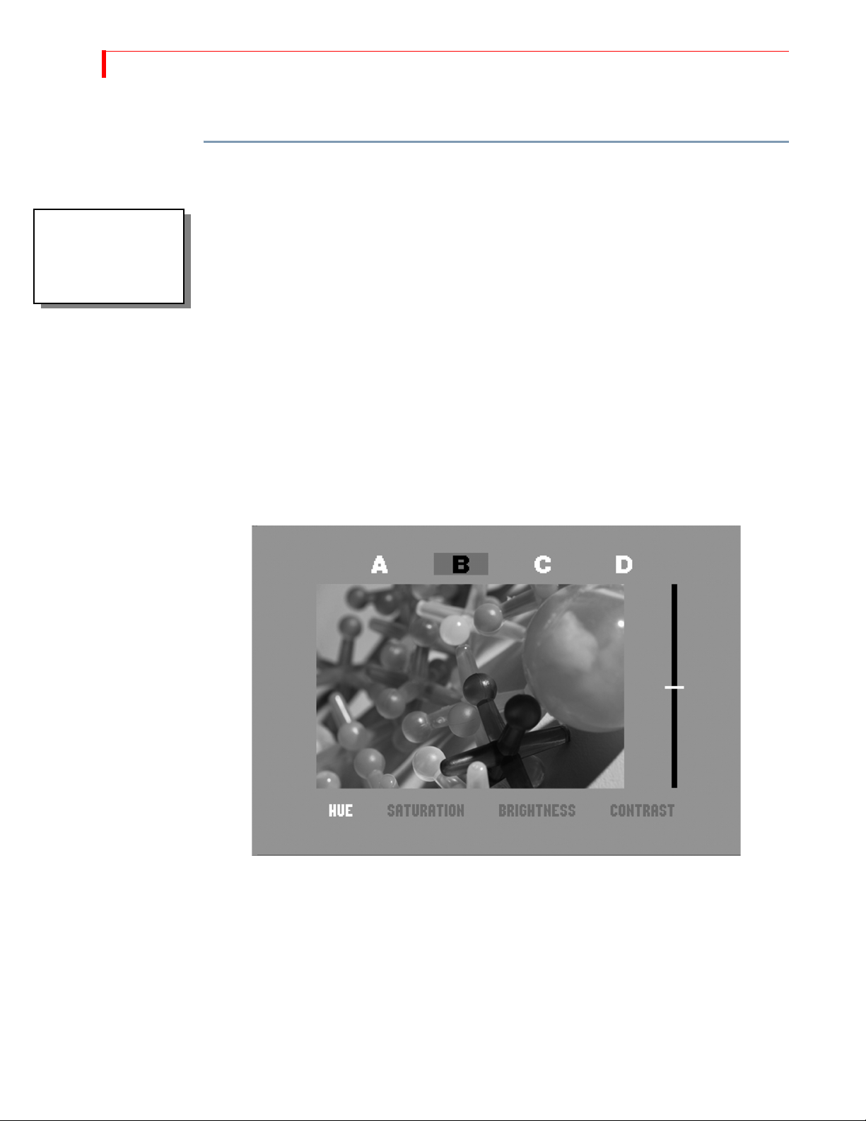
62
MX-4 DV USER GUIDE CHAPTER 6
USING INPUT EFFECTS
To apply a parameter value:
1 Press EFFECTS or one of the input effects buttons to display the Input Effects menu.
Please select a
channel source before
choosing an Input
Effect.MX-4 DV.
2 If you haven’t already done so, use the
ARROW keys or EFFECTS button to select the desired
Input Effect to which you want to apply parameter values.
3 Set the parameter value to 0 (zero) to turn it OFF, or to 1 to turn it ON.
4 Use one of the
example, press
NEXT buttons to select the source to which you want to apply the effect. For
NEXT/B to apply the effect to channel B.
5 Type the parameter value on the MX-4 DV numeric keypad, or continue pressing the corre-
sponding effects key until the parameter value you want appears in the menu.
6 Press
OK to exit from Input Effects mode.
7 You can also use the Input Effects Menu to access the Video Adjustment Menu for Brightness,
Contrast, Color Saturation, and Hue. Use one of the
you want to apply the adjustments. Use the
option. Press
OK to go to the Video Adjustment Menu. You can also press SHIFT+PLAY to go
ARROW keys to select the Video Adjustment
NEXT buttons to select the source to which
straight to the Video Adjustment Menu from any other menu. To reset to the original factory
settings, press the
SHIFT then OK button.
8 Inside the Video Adjustment menu, select the proper video adjustment (Brightness, Contrast,
Color Saturation, and Hue) with the
video adjustment, make the proper adjustments with the
T-BAR until you have achieved the desired effect. You can view all adjustments on the Preview
LEFT/RIGHT ARROW keys. Once you have selected the
UP/DOWN ARROW keys or with the
screen.
The MX-4 DV stores the most recent set of input effects. Therefore, when you turn the unit off,
then turn it back on again, the most recent selection of input effects is still active.
Page 67
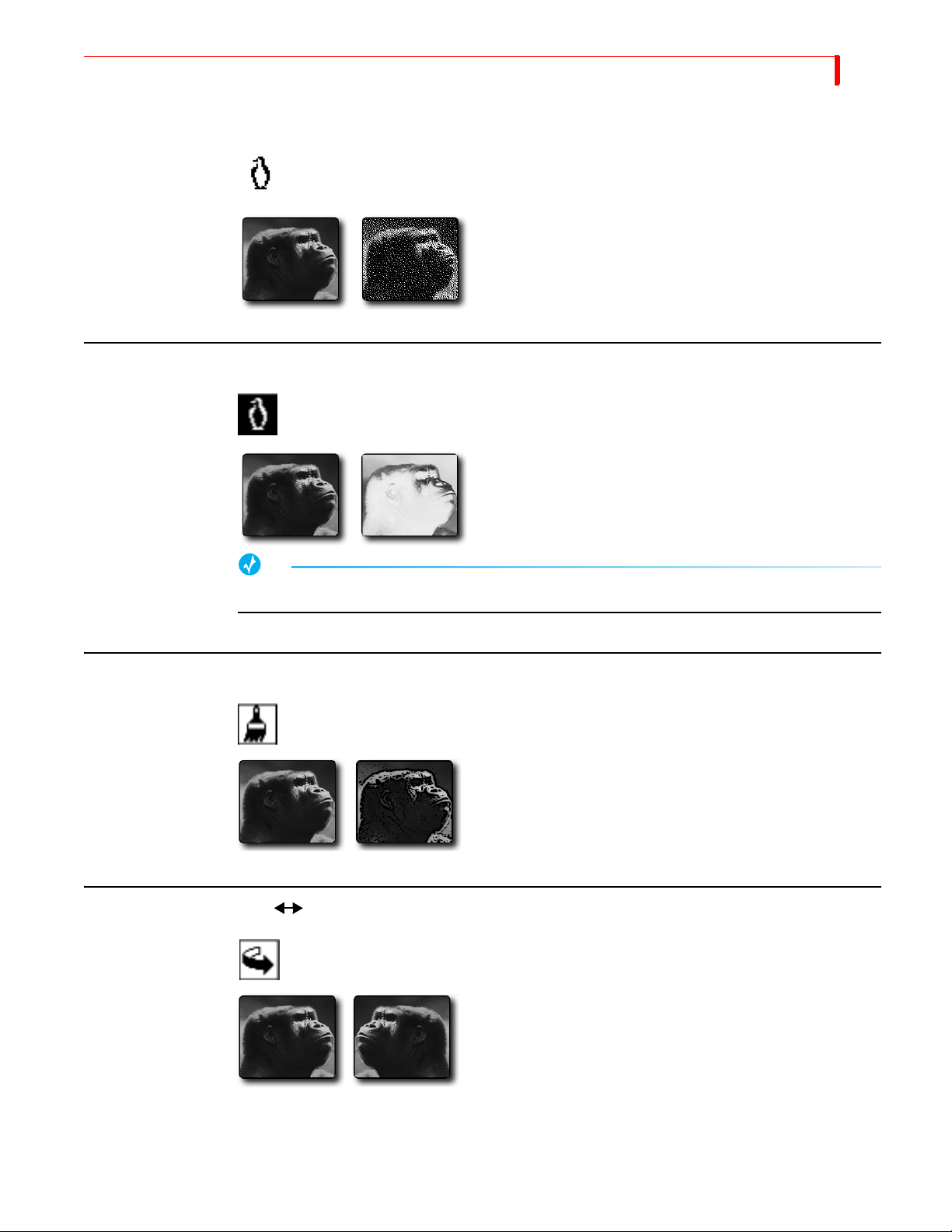
INPUT EFFECTS B&W
B&W
Changes the input picture to black and white. Removes all
color from the image.
Parameter Values — Zero or one.
0 = Off: 1 = On
B&W NEG
Reverses all black and white values in the image. If applied to
a color image, reverses all black and white values but does
not change any color values in the image.
Parameter Values — Zero or one.
0 = Off: 1 = On
63
POSTERIZE
FLIP HORIZONTAL
TIP
To create a black and white negative effect, also turn on the B&W effect.
Reduces picture’s continuous tones to fewer levels. Creates a
“painted” look.
Parameter Values — Zero through nine. Zero turns off the
effect.
High values produce an extreme paint effect: low values create a subtle effect.
Flips picture left-to-right, creating a mirror image.
Parameter Values — Zero or one.
0 = Off: 1 = On
Page 68
64
MX-4 DV USER GUIDE CHAPTER 6
MOSAIC
COLOR CORRECT
Divides picture into tiles.
Parameter Values — Zero through nine. Zero turns off the
effect.
Low values create numerous, small tiles. High values create
fewer, larger tiles. Highest values might make image difficult
to recognize.
Adjusts overall color values throughout the entire image.
You can set Color Correction values separately for each channel.
Parameter Values — Zero or one.
0 = Off: 1 = On
COLOR NEG
CAUTION
Apply color correction BEFORE going live or rolling tape. Because of the way the MX-4 DV
implements color correction, the program output might be affected temporarily.
To use Color Correct:
1 Press COLOR CORRECT to display the Input Effects menu, or press EFFECTS then use the
ARROW keys to highlight the Color Correct icon.
2 Press the
apply color correction to channel C, press
NEXT button that corresponds to the source you want to correct. For example, to
NEXT/C.
3 Turn on the Color Correct option. That is, either press 1 on the keyboard, or press COLOR
CORRECT so the parameter value equals 1.
The MX-4 DV replaces the Input Effects menu with a preview of the color corrected image.
4 Use the
5 Use the
JOYSTICK to adjust the RGB (Red, Green, and Blue) values in the image.
T-BAR to adjust the luminance of the image. You can do fine-grained adjustment with
the arrow keys (and shift arrow keys), just like in the Learn color mode.
6 When the image looks the way you want, press
OK to exit from Input Effects mode.
Inverts all colors in the image.
Parameter Values — Zero or one.
0 = Off: 1 = On
Page 69
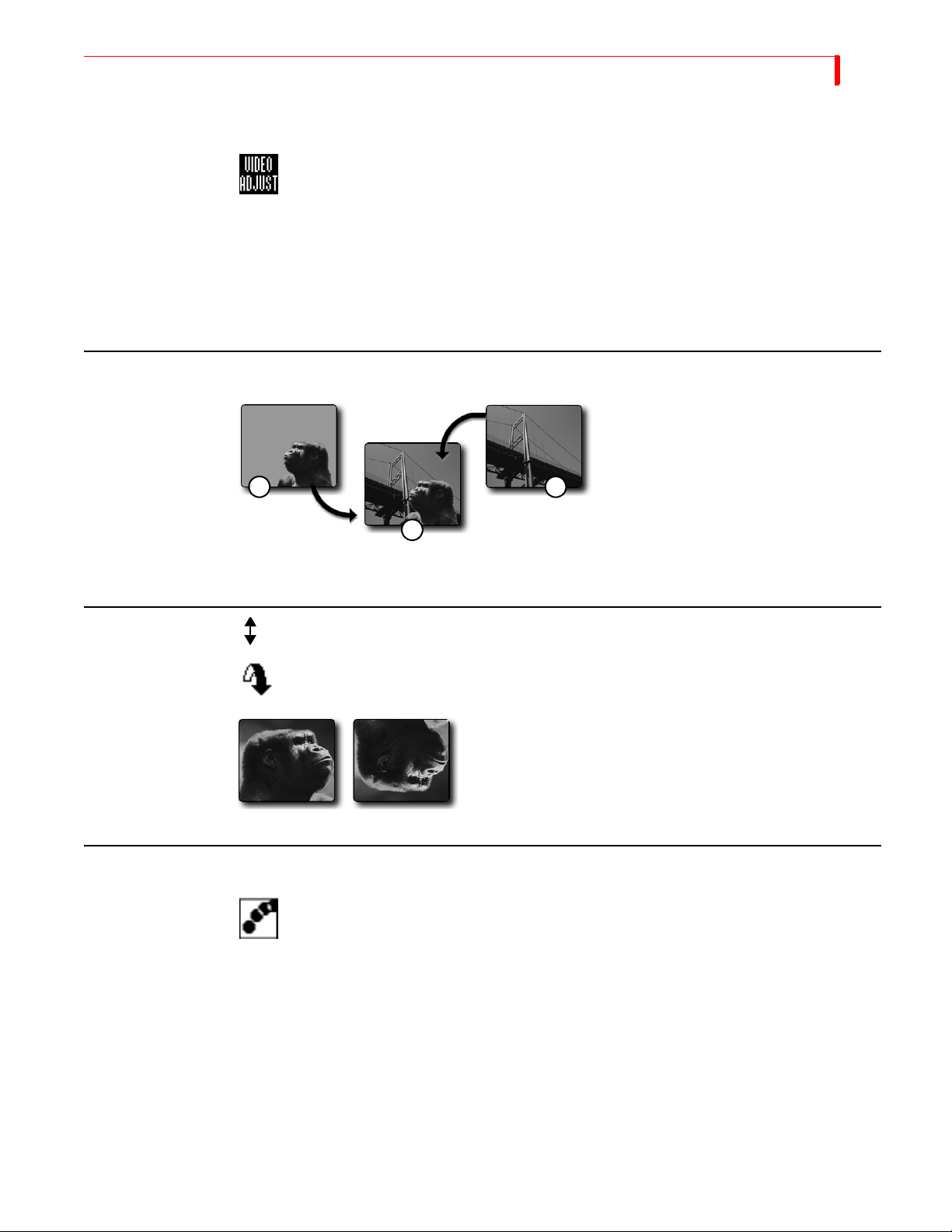
INPUT EFFECTS VIDEO A DJUSTMENT
VIDEO ADJUSTMENT
Allows you to access the Brightness, Color Saturation, Contrast, and Hue adjustment
menu. Use the
guides you to the video adjustment menu. Refer to “Using Input Effects” on page 62
for complete details.
Parameter Values — Zero or one.
ARROW keys to select this option, then press OK. The MX-4 DV then
65
CHROMAKEY
FLIP VERTICAL
0 = Off: 1 = +
12
OK activates video adjustment menu.
3
Flips picture top-to-bottom.
Parameter Values — Zero or one.
Chromakey replaces all occurrences of a
color in an image with a different image.
In this example, (1) the block of color in
the first image (the area behind Kong’s
head) gets replaced with the image of the
Golden Gate Bridge (2). The resulting
image (3) is Kong superimposed over the
bridge. Refer to Chapter 10, Chromakey,
for complete details.
STROBE
0 = Off: 1 = On
Slows down the picture’s video frame rate. Motion appears halting, or jerky — like
that produced by a strobe light. The strobe effect stays on during a transition.
Parameter Values — Zero through nine. Zero turns off the effect.
Higher values increase the effect. Setting 1, for example, produces the look of film:
setting 2 makes video look like an old movie.
Page 70

NOTES
Page 71
CHAPTER 7
FUNCTIONS
This chapter describes the Function buttons, that give you access to the MX-4 DV’s built-in
functions. The function button group contains eight buttons, but gives you access to more
than eight functions.
Page 72
68
DEMO
MX-4 DV USER GUIDE CHAPTER 7
Press SHIFT+DEMO/DISPLAY to run a demonstration of several MX-4 DV transitions and other
effects. Demo works in conjunction with the CURRENT and NEXT sources. (If you have one
source selected as CURRENT and NEXT, the demo works with that source only.) The demo shows
many of the effects you can produce with the MX-4 DV.
The demo runs automatically and, upon reaching the end, starts over from the beginning.
To run the demo:
1 Select the CURRENT and NEXT sources to use for input to the demo.
To use a single source (such as channel A), press CUT/A and NEXT/A. To use two different
sources (such as channels A and B), press
NEXT/B to make it the NEXT source.
CUT/A to make it the CURRENT source, then press
2 Press SHIFT+DEMO/DISPLAY to start the demo running.
3 To exit from the demo, press any key.
TIP
If you see a transition you like while the demo runs, immediately press any key to stop the Demo.
When the Preview screen returns, the last transition run is highlighted in the Transitions Menu.
Make a note of the transition number, then add it to your custom User Transitions Menu. Refer to
“Changing User Transitions Menu” on page 52.
Running a Locked Demo
You can run the demo in locked mode, which prevents it being stopped by pressing any key on the
keyboard. This might be useful for running the demo in a kiosk, a trade show, or anyplace where
someone might interrupt it.
To run the demo in Locked mode:
1 Select the CURRENT and NEXT sources to use for input to the demo.
To use a single source (such as channel A), press
sources (such as channels A and B), press
NEXT/B to make it the NEXT source.
2 Press
3 To exit from the locked demo, press
CUT/A and NEXT/A. To use two different
CUT/A to make it the CURRENT source, then press
LEARN+DEMO/DISPLAY to start the demo.
LEARN+DEMO/DISPLAY again.
Page 73

FUNCTIONS DISPLAY
DISPLAY
To control what appears on the Preview monitor, use the DISPLAY function. Press DEMO/DISPLAY
to cycle through the different display configurations. Refer to samples of these configurations on
the next page. The illustrations show the key combination you can use to directly access any
display configuration.
TANDARD – Provides most extensive display. Shows preview images of all active input
S
sources and a menu of up to 30 different transitions from which you can choose.
T
WO CHANNEL – Displays preview images for the CURRENT and NEXT sources. Preview
images increase in size, but the Transitions Menu shows only 20 transitions.
F
ULL – Divides preview screen into four sections. Each section shows a preview image of the
currently active input sources. The Transitions Menu is not available.
N
EXT – Displays only a full-screen preview image of the NEXT source.
C
URRENT – Displays only a full-screen preview image of the CURRENT source.
69
Page 74
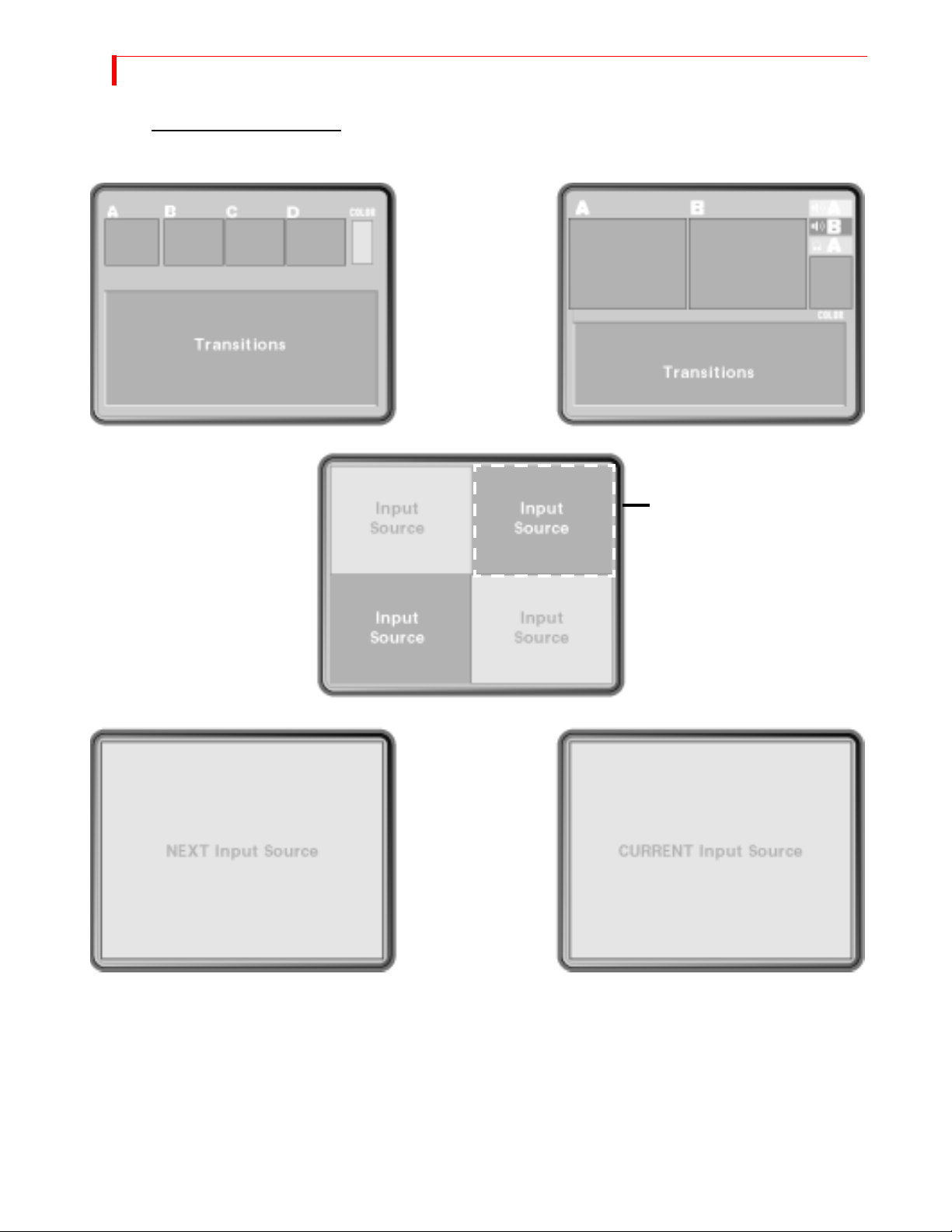
70
MX-4 DV USER GUIDE CHAPTER 7
DISPLAY CONFIGURATIONS
Standard – SHIFT+1 Two Channel – SHIFT+2
Flashing white border indicates
Full – SHIFT+3
CURRENT source, unless that
source is the COLOR channel.
For all examples on this page,
assume source A is CURRENT and
source B is NEXT. Input sources C
and D show up only when using
Standard or Full options.
Current – SHIFT+5Next – SHIFT+4
Use the shortcut keys or press
DISPLAY to cycle through the
display options.
Page 75
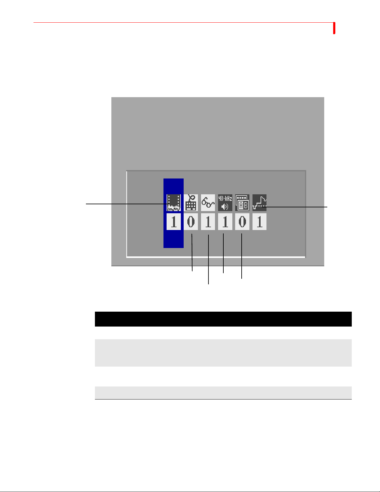
FUNCTIONS SETUP
SETUP
The Setup functions control various aspects of the way the MX-4 DV operates, including Force
Field Freeze, GPI Out Mode, Comb Filter, Dual Monitor Mode and 7.5 IRE Pedestal.
71
Force Field
Freeze
To access the Setup functions, press
SETUP.
7.5 IRE
Pedestal
GPI Out Mode
Audio Mode
Dual Monitor Mode
Comb Filter
Table 8: Setup Menu Navigation Keys
TO DO THIS FUNCTION: ENTER NOTES
Select a menu option
Enter specific option value
LEFT or RIGHT ARROW
NUMBER keys
Wraps through all options
If value entered is not
valid, the MX-4 DV sets
to the nearest valid value.
Restore setup values to factory
SHIFT+0
defaults.
Exit from Setup menu
OK
Page 76
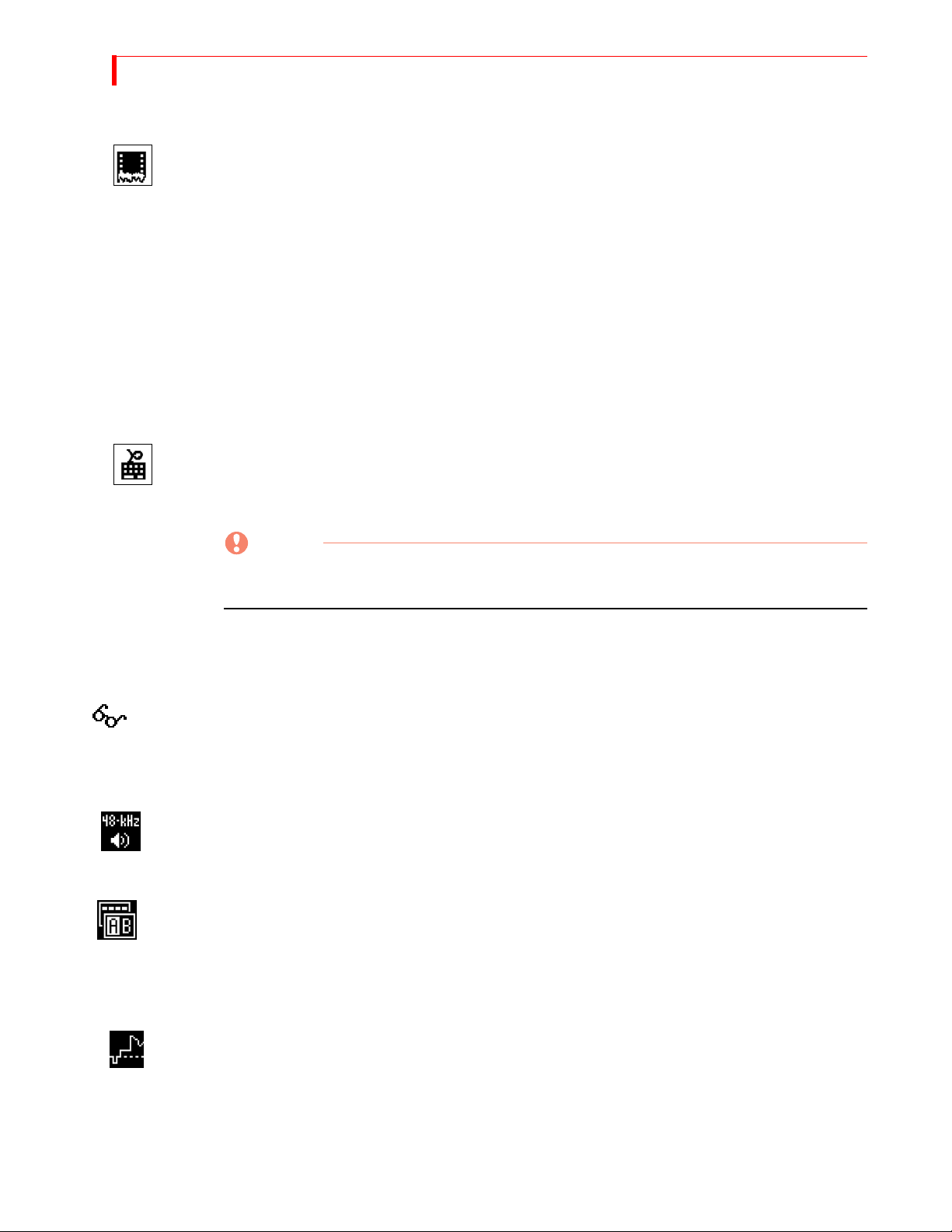
72
MX-4 DV USER GUIDE CHAPTER 7
Force Field Freeze
GPI Out Mode
The Force Field Freeze option lets you specify whether you want the MX-4 DV to perform a frame
or field freeze. This option works in conjunction with the Freeze feature (refer to “Freeze” on
page 79).
Frame Freeze produces best quality, but it might produce a jittering effect when trying to freeze
objects in motion. In such cases, use a Field Freeze.
Field Freeze – The MX-4 DV freezes only every other line of the image. This produces a fast
freeze, but image quality degrades somewhat. To use Field Freeze, set the Force Field Freeze
option to 1.
Frame Freeze – The MX-4 DV freezes every line in the image. The freeze takes slightly
longer, but the image quality matches the original because it uses all of the video signal. To use
Frame Freeze, set the Force Field Freeze option to 0 (zero).
This setting determines whether the MX-4 DV provides a GPI output to an external device, such
as a character generator, thereby allowing you to trigger an external event based on an action from
the MX-4 DV. Set the value to 0 (zero) to use the MX-4 DV with an edit controller. Set the value to
1 to enable GPI output to trigger a character generator, such as the Videonics TitleMaker.
Refer to “Using a GPI Device” beginning on page 120 for relevant information.
Comb Filter
This option can be used in some cases to affect the quality of the video coming from an input
source. Normally, you should leave this set at the default – 1 or On. Change it only if asked to do so
by a FOCUS Enhancements Customer Support Representative.
Audio Mode
This option allows you to choose between 32-kHz and 48-kHz audio on DV OUT. Set the value to
0 (zero) for 32-kHz audio, or 1 for 48-kHz audio.
Dual Monitor Mode
This lets you specify whether you want the MX-4 DV to run the selected transition on both the preview and program monitor at the same time with a setting at 0. As an alternative, you can keep the
preview screen constant while the transition takes place on the program monitor only with the setting at 1.
CAUTION
The MX-4 DV also accepts values 2 through 4 for this option. However, using any of these
values might cause your equipment to malfunction and should not be used.
7.5 IRE Pedestal
NTSC Video equipment commonly uses one of two black level settings:
• 7.5 IRE – The traditional black, which is the MX-4 DV default setting.
• 0 IRE – A darker black level used in Japan.
To use the darker black (0 IRE) for the MX-4 DV background and border colors, set Pedestal to 0
(zero).
Page 77

FUNCTIONS FTP
If you are working with equipment that requires 7.5 IRE, set Pedestal to 1.
NOTE
This option is not available on PAL versions of the MX-4 DV.
FTP
The FTP function lets you network your MX-4 DV to a PC using the Ethernet connector on the
back of you unit. You can copy background, foreground and still frame jpeg images to or from
your unit. Refer to “Ethernet Connection” in Chapter 13 for complete information.
ROUTE
The Route function has the following primary purposes:
• Configure the MX-4 DV to match your equipment.
• Re-direct signals coming from an input device to different or multiple MX-4 DV channels.
73
Configuring the MX-4 DV
The MX-4 DV ships from the factory with the following default options:
• Source Input 1’s video and stereo audio are assigned to Channel A, with the video signal
routed through the DV IN 1 connector.
• Source Input 2’s video and stereo audio are assigned to Channel B, with the video signal
routed through the DV IN 2 connector.
• Source Input 3’s video and stereo audio are assigned to Channel C, with the video signal
routed through the Y/C IN 3 connector.
• Source Input 4’s video and stereo audio are assigned to Channel D with the video signal routed
through the Y/C IN 4 connector.
• Color Source defaults to MUTE.
• BKGD MUSIC Source defaults to MUTE.
• BACKGROUND and FOREGROUND graphics default to OFF.
Unless you tell the MX-4 DV otherwise, it assumes your sources are connected exactly as
described above.
Default Settings for
Route Functions
If your set up does not match the default options, you need to change the Route settings. For example, assume you have an Y/C VCR attached to the input jacks marked 3 (IN3), and a Composite
VCR attached to the input jacks marked 2 (IN2). You don’t need to change anything for the first
input because it matches the default setting. However, because the second source is a Composite
device (rather than DV) you need to notify the MX-4 DV of this fact.
Page 78

74
MX-4 DV USER GUIDE CHAPTER 7
Changing the Routing
To change the routing,
1 Press ROUTE to display the Route menu.
The MX-4 DV has four internal channels: A, B, C and D. The route menu lets you select
which of the twelve inputs are connected to each of the four channels.
Audio sources can be routed to the same four channels (A, B, C and D) and in addition, can be
routed to the color channel (Color) or the background audio channel (BKGD). Refer to Chapter 12, Working with Audio, for more information.
2 Select the channel (A,B,C or D) you want to change by pressing
NEXT/D, NEXT/BACKGROUND, or SHIFT+NEXT/BACKGROUND (for Background Audio). Once
NEXT/A, NEXT/B, NEXT/C,
you select the channel, it is highlighted.
3 Select the video source you want to display for this channel. Use the
ARROW keys to move to the Video row, then use the LEFT ARROW/RIGHT ARROW keys to
UP ARROW/DOWN
select a video source.
a The first choices in each Video Input selection (IN1-4) are composite (V) and Y/C (S)
sources.
b The next choice in each video input section (IN1-4) are DV sources.
c The remaining choice to the right consists of a graphics/gradients input selection. Once
you select this feature and press
OK, a sub menu appears providing the option to select
graphics/gradients or a solid color as an input. Refer to “Sub-Route Menus” on page 77
for more information.
Page 79
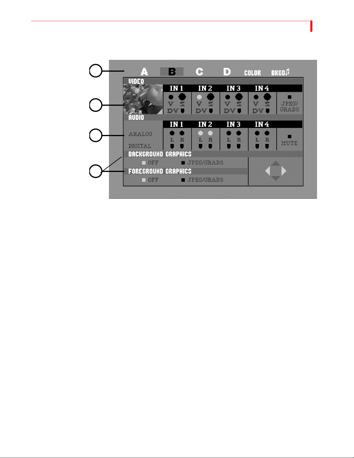
FUNCTIONS EXAMPLE: CHANGING THE ROUTING
2
3
4
5
75
4 Select the Audio source to use with your selected channel. Use the DOWN ARROW key to high-
light the Audio row, then use the
LEFT ARROW/RIGHT ARROW keys to select an audio source.
a Audio can be a stereo pair of inputs from a DV source IN1-4 or from analog inputs IN1-4
b Audio is available to output on DV audio channels 1 and 2 or on analog outputs L1 and
R1, if you select 2-channel 48kHz audio output in the Setup Menu.
c IN1, IN2, IN3 and IN4 can be either mono or stereo sources: you can select the left chan-
nel, the right channel, or both.
d DV sources can have two or four channels of audio inputs. If you use 4-channel sources
and select 4-channel output in the Setup Menu, you can either select channel 1 and 2 or 3
and 4, but not both at the same time. Note that while using 4-channel audio output DV will
only run in 32kHz and not allow mixing and matching. If you select 2-channel audio output in the Setup Menu, it will run at 48kHz on channels 1 and 2.
e Select
f Press
g Press
MUTE if you do not want audio routed to this channel.
SHIFT+NEXT/BACKGROUND to route to the Background Audio channel.
OK or ROUTE to exit the Route Menu.
5 You can select a foreground and/or a background graphic. Once you select this feature, press
OK and the MX-4 DV will guide you into either the foreground or background graphics menu
to select the imported graphic of your choice. When you make the selection, press
ROUTE to
return to the Route menu. Note that you can apply four layer video effects, that can include a
background, foreground and two jpeg inputs all at the same time.
Example: Changing the Routing
In this example, you will change the Routing for Channel C, make video come from DV IN1, and
make Audio come from L1 and R1 or DV IN1 using 2-channel input a 48kHz.
1 Press
ROUTE to display the Route menu.
Page 80

76
MX-4 DV USER GUIDE CHAPTER 7
2 Select the channel by pressing NEXT/C. Verify that channel C is highlighted.
3 Select the Video. Use the
Video row, then use the
UP ARROW/DOWN ARROW keys to move the red highlight bar to the
LEFT ARROW/RIGHT ARROW keys to select DV IN1.
4 Select the Audio channel. Since you are in a 2-channel input, use the UP ARROW/DOWN
ARROW keys to move to the Audio row representing the Digital section, then use the LEFT
ARROW/RIGHT ARROW keys to select L1 and R1 within DV IN 1.
Routing Audio Through Color or Background Channels
Don’t forget that you can route audio through the Color and Background Channels. These are useful for fading to colors while maintaining the same audio source or mixing words with a music
background.
To route audio through the Color or Background Channels:
1 Press NEXT/BACKGROUND or SHIFT+NEXT/BACKGROUND to select the Color or Background
channel. Refer to “Using the Audio Mixer” on page 111.
2 Use the
LEFT ARROW/RIGHT ARROW keys to select the audio of your choice.
Page 81
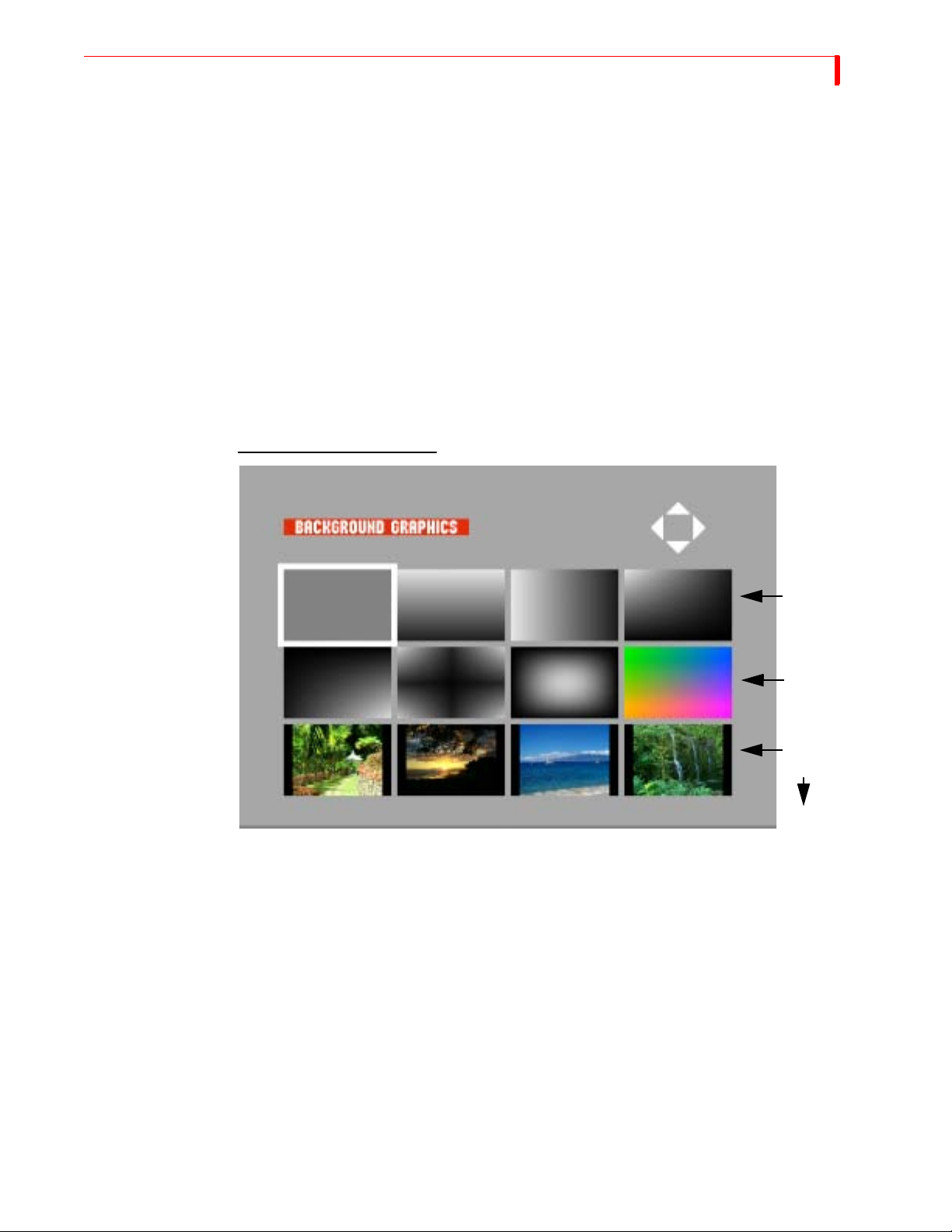
FUNCTIONS SUB-ROUTE M ENUS
Sub-Route Menus
You can select Sub-Route menus for the following:
• Input graphics
• Foreground graphics
• Background graphics
77
Input Graphics and
Background
Graphics Menu
Once you highlight the selection on the Route Menu, press
OK to continue into the selected sub-
menu.
Once you have chosen either a graphic as an input or apply a background graphic from the main
router menu, you will be directed to the menu referenced below. The menu provides eight gradients
and a possible 50 background jpegs to add to your unit.
Use the
COLOR button. To create a custom gradient colors, press LEARN+BG COLOR, and then use the joy-
stick and
ARROW keys to select a graphic. You can change the gradient colors by using the BG
T-BAR to create a new color. When you’re done creating a custom color, press OK.
Background Graphics Menu
Solid
Color
Gradients
Gradients
Importing Graphics
into the Foreground
or Background
Menus
Backgrounds
0-3
4-49
In order to import a jpeg into the Foreground or Background menu, you must first assign a proper
file name. This name must include the specified menu (background or foregrounds) and placement
within the selected menu (0-49 foregrounds, 0-49 backgrounds).
Example: Back_08.jpeg
Once you complete your file name configuration, you can then import the jpeg files using the
Ethernet port on the back of the unit and by using the standard FTP software. Refer to “Transferring Files TO or FROM the MX-4 DV” on page 130, for complete details.
The MX-4 DV comes with the following installed 12 inch Design background and foreground
jpegs:
Background_00.jpeg through Background_49.jpeg
Foreground_00.jpeg through Foreground_49.jpeg
Page 82
78
n
MX-4 DV USER GUIDE CHAPTER 7
Importing jpegs for background, input or foreground use will automatically replace what currently
exists on your MX-4 DV. A factory reset will not restore the original 12 inch Design jpegs that are
included on the MX-4 DV. Refer to the included CD or use the FOCUS Enhancements website to
re-import the original jpegs if desired.
Foreground
Graphics Menu
Once you have selected “foreground graphics” from the main router menu, you, are directed to the
menu below. It allows you to select various jpeg images. They can be imported and stored using
the Ethernet port located on the back of the MX-4 DV.
To make a selection from the Foreground Menu, use the following steps.
1 Use the ARROW keys to select a graphic.
2 Once you have selected a graphic, press ROUTE to return to the Router menu, or OK to return
to the Preview screen.
3 Use the joystick to position the graphic on the program side before presenting it as a live feed.
4 Use the
presenting it as a live feed. You can also use the number keypad to adjust the transparency of
the foreground log.
The foreground is now ready to be included in a live application.
Foreground Graphics Menu
T-BAR to adjust (on the program side) how transparent you would like the logo before
Correspondi
Foreground
Slots
LEARN
Foregrounds
0-3
4-7
The Learn feature consists of one or more Learned Environments. Within each Learned Environ-
ment you can create a Learned Script.
In a Learned Script you teach the MX-4 DV about a series of transitions and edits you want to
include in a production. This is similar to using an Edit Decision List (EDL), though not as flexible
or powerful.
8-11
12-49
Page 83
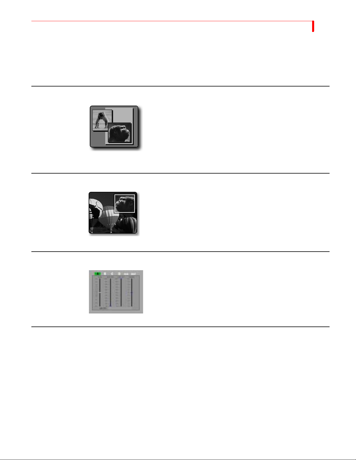
FUNCTIONS COMPOSE
Once you activate the Learn feature, the MX-4 DV remembers each step you go through in
preparing a production — including all transitions, input effects, and other operations. You can
play back this Learned Script to automatically perform all of the steps and functions it contains.
Refer to Chapter 11, Learn Mode, for complete information.
COMPOSE
Use Compose to create screen images made up of several different graphic
elements. For example, a composed screen might show two still images
(polar bears and Kong) placed atop solid colored rectangles and a solid
colored background. With a character generator (such as the Videonics
TitleMaker), you can also add text elements to composed screens. Refer to
Chapter 9, Compose.
PIPS
PIPs (Picture-In-Picture) let you combine images from separate sources
and place them on the screen at the same time in separate windows (or,
tiles). You have many options for arranging the PIP windows on the
screen. Refer to Chapter 8, PIPs.
79
AUDIO MIX
FREEZE
The Freeze effect immediately freezes the selected video source.
This section describes the types of freeze effects you can produce with MX-4 DV and how to use
Freeze with transitions.
You can also use the Freeze effect with the MX-4 DV PIP and Compose features. Refer to Chapter
8, PIPs, and Chapter 9, Compose, for further information.
Field and Frame Freezes
You can freeze either a video field, or a full frame.
Field Freeze – Captures every other horizontal line of the video. This is ideal for capturing
anything in motion.
Use Audio Mix to adjust audio levels for any channel. Refer to Chapter
12, Working with Audio.
Page 84

80
MX-4 DV USER GUIDE CHAPTER 7
Frame Freeze – Captures all horizontal lines, thereby producing a higher resolution (better
quality) image. Use Frame Freeze when working with still images, such as photographs. Using
Frame Freeze with images in motion normally produces jitter in the movie.
The MX-4 DV captures using Frame Freeze, by default. Refer to “Force Field Freeze” on page 72
to learn how to change the default setting.
Major Freeze Functions
The MX-4 DV provides three major freeze functions: Freeze Current, Freeze Next, and Freeze
During (Transitions).
Freeze Current Freezes the image on the Program Output device.
•
To freeze the video on the current source, press FREEZE.
•
To unfreeze the video on the current source, press FREEZE again.
Freeze Next Freezes the video on the Next source. This is useful for freezing an image, then transitioning to it.
•
To freeze the video on the Next source, enter SHIFT+FREEZE.
• To unfreeze the video on the Next source, e
nter SHIFT+FREEZE, again.
Freeze During
(Transition)
Freeze Examples
Single Source
(A/A) Editing
Stops the current transition and freezes both the Current and Next video sources.
• Freeze during transition works the same as Freeze Current and Freeze Next. FREEZE toggles the
freeze state of the current source and
•
FREEZE no longer pauses or unpauses the transition.
SHIFT+FREEZE toggles the freeze state of the NEXT source.
This section discusses some common uses for the Freeze function. As you use the MX-4 DV over
time, you’ll probably create many others ways to use this function.
When working with a single source, use the Freeze function to transition to or from the second
image.
To use Freeze with Single Source Editing:
1 Route the same video source to Channel A and Channel B.
Use the CUT/A and NEXT/B buttons to specify Source A as the Current Source and Source B as the
2
Next Source.
3 Enter
SHIFT+4 to select Preview NEXT mode on the Preview Monitor.
4 Press FREEZE to freeze the Current source.
The MX-4 DV freezes the Current source on the Program monitor, and the Next source (on the
Preview monitor) continues moving even though there is only one source (routed to two channels).
Enter 1, OK, PLAY to run a simple dissolve transition. The frozen image dissolves to moving video.
5
6 Press SHIFT+FREEZE to release the freeze on the Next source.
To freeze and dissolve back and forth, repeat steps 3 through 5.
The following steps explain how to transition from moving video to a still image.
Enter SHIFT+FREEZE to create a still frame on the Next source.
7
8 Enter 1, OK, PLAY to dissolve from the Current moving video to the Next still image.
9 Press FREEZE to release the freeze on the Current source.
Page 85

FUNCTIONS FREEZE E XAMPLES
81
Creating Still
Montages
You can use the Freeze function to transition between a series of still images to create a “still montage.” You can use from one to four sources.
To create a still montage:
1 Route a video source to Channel A. Remember, you can use up to as many as four sources for
this procedure.
This example starts from a black screen, then transitions to a still image.
2 Enter
BG COLOR+0 (zero) to set the background color to black.
3 Press CUT/BACKGROUND to set the Color Channel as the Current source. You now have a
black screen on the Program monitor.
4 Press
NEXT/A to set Channel A as the Next source.
5 Enter SHIFT+4 to set the Preview monitor to Preview Next mode.
You’re now ready to create and transition to the first still image.
6 Enter SHIFT+FREEZE to create a frozen image on the Next channel.
7 Enter 1, OK, PLAY to dissolve from black to the first frozen image.
The NEXT and CURRENT sources swap positions. You’re now ready to select the second still
image.
8 Press any
NEXT button to select a new source to freeze.
9 Enter SHIFT+FREEZE to freeze the NEXT image.
10 Enter 1,
OK, PLAY to dissolve to the NEXT image.
To transition to other still images, repeat steps 8 through 10.
Page 86

82
MX-4 DV USER GUIDE CHAPTER 7
NOTES
Page 87
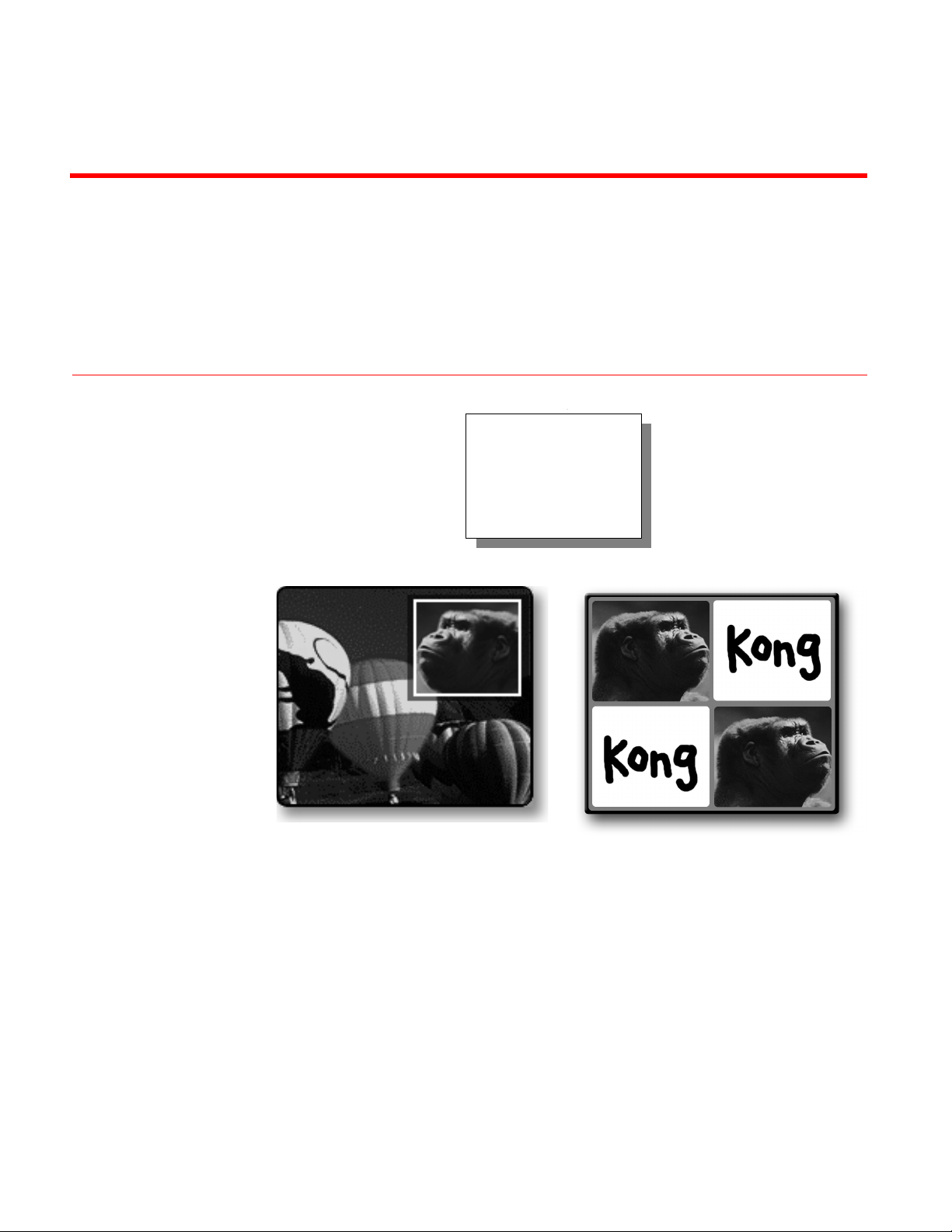
With the MX-4 DV you
can easily produce
single and multiple
Picture-in-Picture
displays.
CHAPTER 8
PIPS
Multi-PIPSingle PIP
PIP (Picture-In-Picture) provides a way to combine images on the same screen. For exam-
ple, one image appears inside a small rectangle, and the other image fills the remainder of
the screen as shown by Single PIP, above.
You can freeze the background or foreground, or make either one a solid color.
You can create Single PIP configurations where two images appear on the screen at the
same time. You can also create Multi-PIP configurations where up to four images appear on
the screen at the same time. Single PIP and Multi-PIP work differently.
PIP images consist of a tile (the video image) and a mask (the window or shape through
which the tile shows).
Page 88
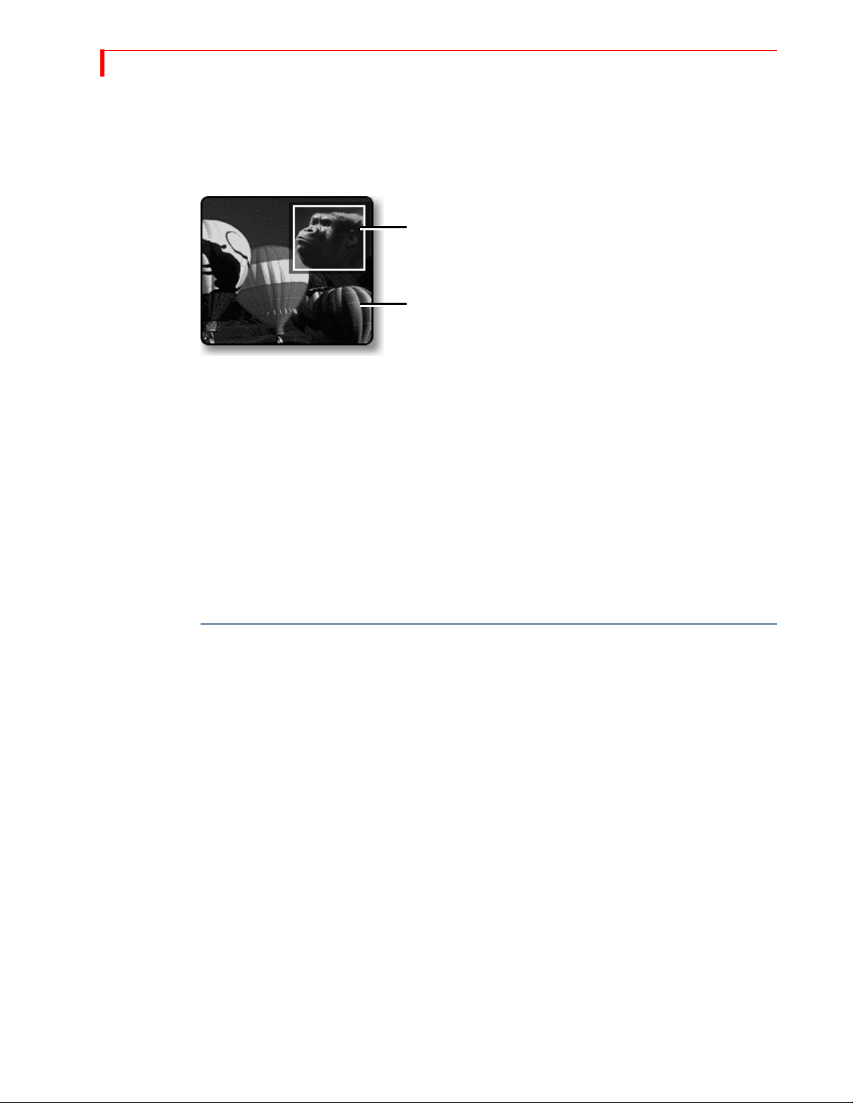
84
MX-4 DV USER GUIDE CHAPTER 8
SINGLE PIP
Background Tile
In a single PIP configuration, one tile fills the background while another tile and its mask float atop
the background. The CURRENT source always serves as the background tile; the NEXT source
always serves as the PIP image.
Foreground Tile and Mask
…from NEXT Source
Background Tile
…from CURRENT Source
The background tile always fills the entire screen. You can apply Input Effects (Strobe, Freeze, and
so forth) to the background tile, or make the tile a solid color. You cannot otherwise change the
background tile in any way.
Foreground Tile
You can manipulate the foreground tile and mask in different ways, such as:
• Position the tile anywhere on screen.
• Change the size and shape of the tile and its mask.
• Create a border around the tile.
• Reposition, resize, and otherwise change the mask without changing its corresponding tile.
To create and apply a single PIP:
1 Assume the background image originates on input source A. Press CUT/A to make source A the
CURRENT source. It serves as the background tile.
If you want, instead, to make the background a solid color, press
CUT/BACKGROUND. Refer to
“Using Color Backgrounds” on page 42 to learn how to select colors.
2 Assume the image of the gorilla originates on input C. Press
NEXT/C to make source C the
NEXT source. It serves as the foreground tile.
3 Press
PIPS to enter PIP mode. The Preview screen shows the background video with the fore-
ground video inset in a small tile.
4 Press
NEXT/A, NEXT/B, NEXT/C, NEXT/D, or NEXT/BACKGROUND to change the image in the
PIP window.
5 Press
PLAY to display the PIP on the Output.
6 To exit PIP mode, press
PIPS.
Page 89
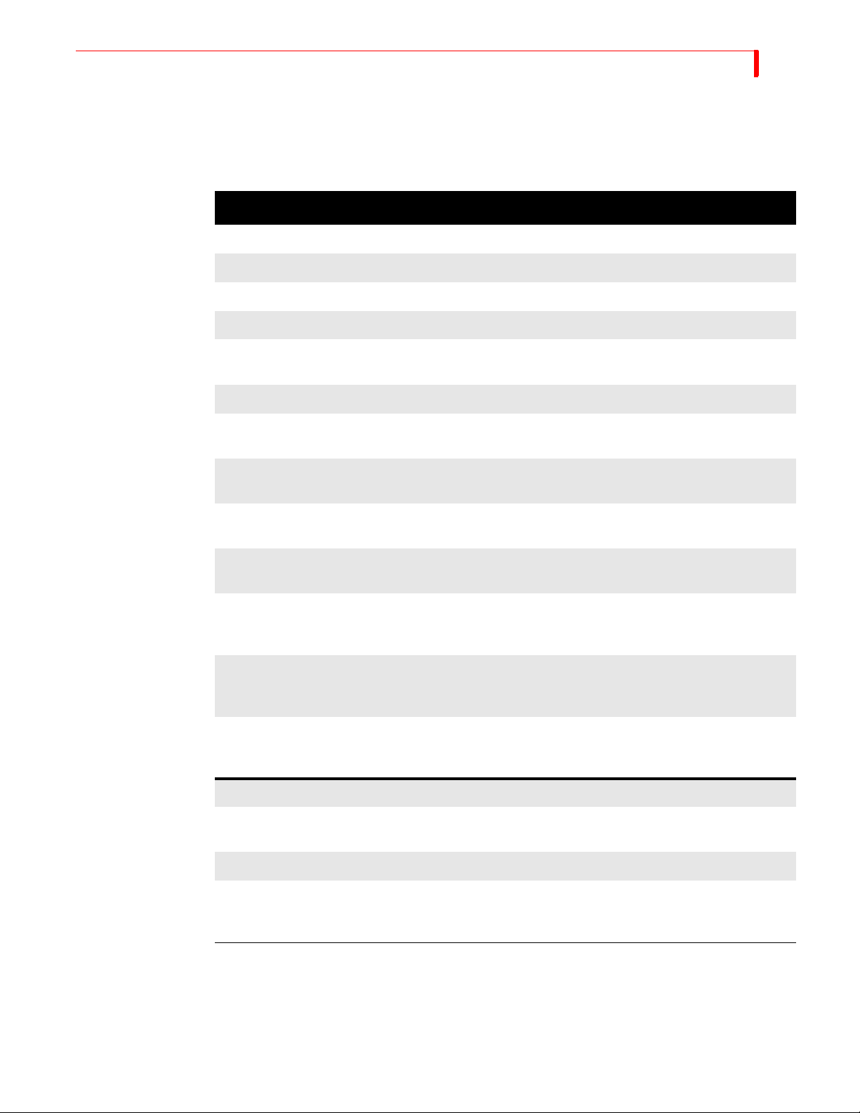
PIPS FOREGROUND T ILE
85
Manipulating the
Foreground Tile
This section explains how to change the position, size, shape, and so forth of the foreground tile. In
each case, do the steps after pressing
PIPS, as described in the preceding steps. You can do any of
these steps while the PIP plays on the Output.
Table 9: Manipulating PIPs Tiles
TO CHANGE TILE… USE OR PRESS… NOTES…
Position
JOYSTICK
OK+JOYSTICK
Moves the tile and its mask around the screen.
Moves the tile around the screen.
Size (Resizing the tile normally distorts the image it contains.)
T-BAR
OK+T-BAR
UP ARROW
Resizes the foreground tile and its mask. Use
T-BAR to manually zoom the image.
the
Resizes the foreground tile.
Increases the height of the foreground tile and
its mask.
DOWN ARROW
Decreases the height of the foreground tile and
its mask.
Shape
RIGHT ARROW
Increase the width of the foreground tile and its
mask.
LEFT ARROW
Decrease the width of the foreground tile and its
mask.
SHIFT+FLIP ▲
Snaps the PIP tile and its mask to the normal
aspect ratio base on the current horizontal
dimensions.
SHIFT+FLIP ▼
Snaps the PIP tile and its mask to the normal
aspect ratio base on the current vertical dimensions.
SHIFT+0 (zero)
Restores the PIP tile to the default size, shape,
and position.
SHAPES
Cycles through available shapes for foreground
tile.
SHIFT+SHAPES
Cycles backward through shapes.
n Applies a specific shape to the tile, where n cor-
responds to the numbers shown in the shapes
following this table.
Page 90
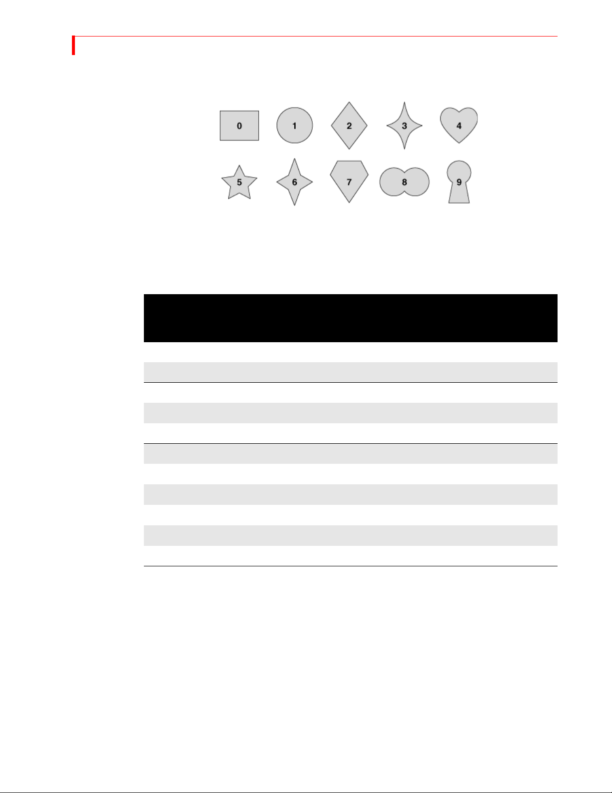
86
MX-4 DV USER GUIDE CHAPTER 8
You can apply the following shapes to PIP tiles. To select a shape, press the numeric key (0 through
9) that corresponds to the shape you want, as indicated below.
Manipulating the
Mask
Additional shapes can be selected for PIP mode using the
SHAPES button.
The mask changes shape, size, and position when you change the corresponding attribute of the
foreground tile. You can, however, manipulate the mask independently, as discussed in this section.
Table 10: Manipulating PIPs Mask
TO
CHANGE
MASK…
USE OR PRESS… NOTES…
Position
SHIFT+JOYSTICK
Change mask position.
Style (Press keys repeatedly to cycle through available colors and styles.)
BORDER COLOR
BORDER STYLE
Change mask border color.
Change mask border style.
Size
SHIFT+T-BAR
SHIFT+UP ARROW
SHIFT+DOWN ARROW
Change mask size.
Increase vertical size of mask.
Decrease vertical size of mask.
SHIFT+RIGHT ARROW
SHIFT+LEFT ARROW
Increase horizontal size of mask.
Decrease horizontal size of mask.
Using Other Effects with Single PIPs
Input Effects You can apply any of the input effects (refer to Chapter 6, Input Effects) to the background and
foreground tiles. Apply the input effect(s) you want prior to entering PIP mode.
The Freeze Effect You can apply the Freeze effect (refer to “Freeze” on page 79) to the background and/or fore-
ground tile.
Press
FREEZE while in PIPs mode to freeze the background. Press FREEZE again to release the
freeze effect.
Press
SHIFT+FREEZE while in PIPs mode to freeze the foreground tile. Press SHIFT+FREEZE again
to release the freeze effect.
Page 91
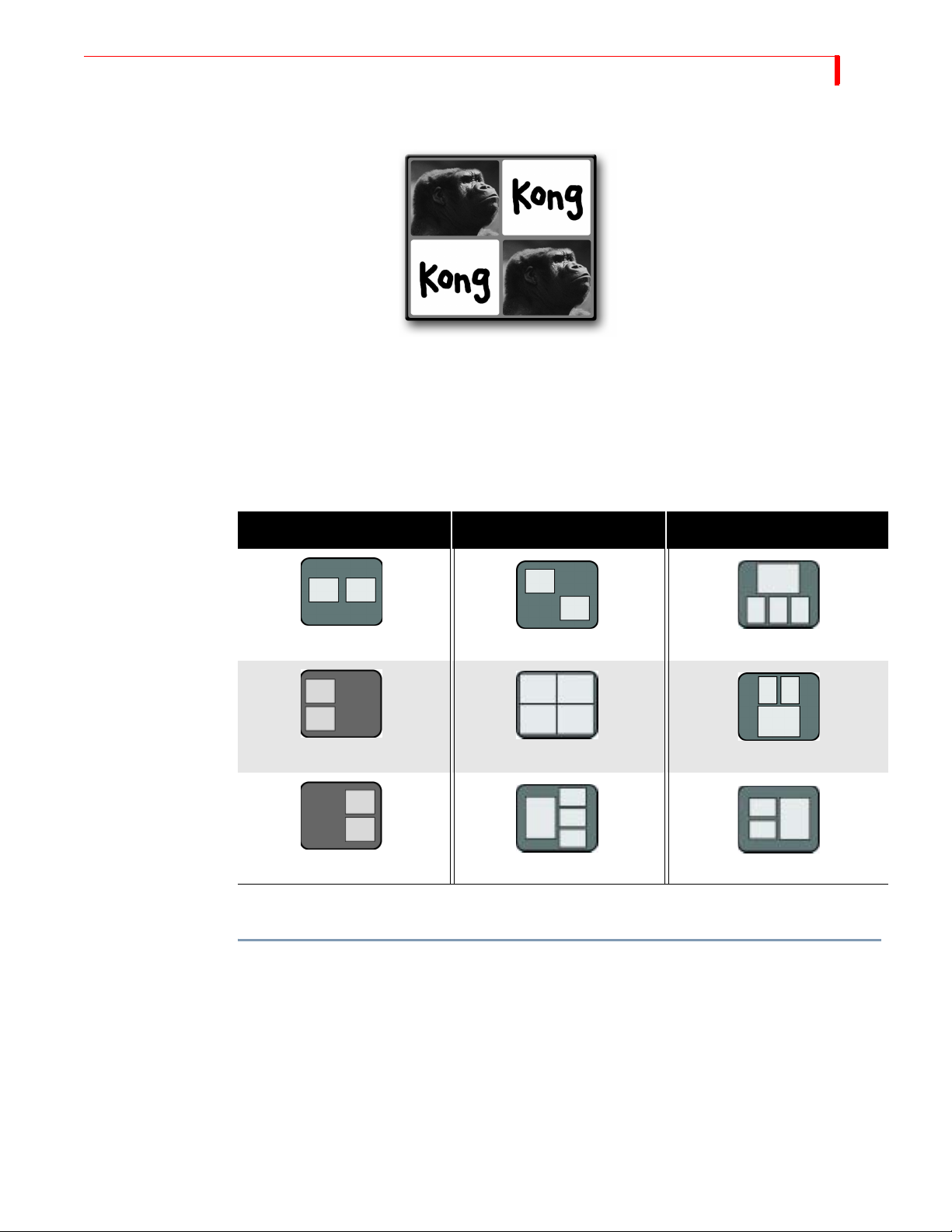
PIPS MULTI-PIP
MULTI-PIP
In Multi-PIP, as many as 4 separate images can share the screen at the same time. Each image appears inside
a separate tile.
You can use any of the four input sources to provide the images that appear in the tiles.
You can choose from 9 different multi-PIP configurations by pressing the number keys shown in
the following table.
Table 11: Multi-PIP Screen Configurations
87
NO. CONFIGURATION NO. CONFIGURATION NO. CONFIGURATION
147
2 5 8
369
The following procedure explains when to specify which configuration you want to use.
To create a multi-PIP image such as the one shown above:
1 Assume the image of Kong originates on input source A. Press
CUT/A to make source A the
CURRENT source.
If you want, instead, to make the background a solid color, press
CUT/BACKGROUND. Refer to
“Using Color Backgrounds” on page 42 to learn how to select colors.
2 Assume the graphic of the word “Kong” originates on input C. Press
NEXT/C to make source C
the NEXT source.
3 Press
SHIFT+PIPS to enter Multi-PIP mode. The Preview screen defaults to show configuration
1 (two horizontal tiles). One of the tiles has a flashing border to indicate it is the current tile.
One tile shows the primary input – Kong’s head.
Page 92

88
MX-4 DV USER GUIDE CHAPTER 8
4 If this is the Multi-PIP configuration you want to use, move on to the next step: otherwise…
a Press the number on the keyboard that corresponds to the PIP configuration you want to
use. (Refer to Table 11, “Multi-PIP Screen Configurations,” on page 87, at the beginning
of this section.) MX-4 DV displays the configuration on the Preview screen.
5 Use the
ARROW keys to move the flashing border to a tile where you want to display the sec-
ondary input source: or, press
column.
6 Press
NEXT/C. Channel C, in this example, carries the video of the graphic word “Kong.” That
image appears in the tile you selected in the preceding step.
7 Repeat the two preceding steps for any other tile or tiles you want. You can direct any input
signal to any tile by using one of the
8 When the Preview screen looks the way you want, press PLAY to cut to the Multi-PIP on the
output; or use the
9 Press SHIFT+PIPS to return to the Preview screen.
Using Freeze Effect with Multi-PIPs
You can apply the Freeze effect (refer to “Freeze” on page 79) to any Multi-PIP tile.
To use the Freeze effect with Multi-PIPs:
1 Use the ARROW keys to select a Multi-PIP tile.
2 Press FREEZE.
3 Press
FREEZE again to release the effect.
SHIFT+ARROW KEY to move to the beginning or end of a row or
NEXT keys.
T-BAR to fade the Multi-PIP to the output.
Page 93
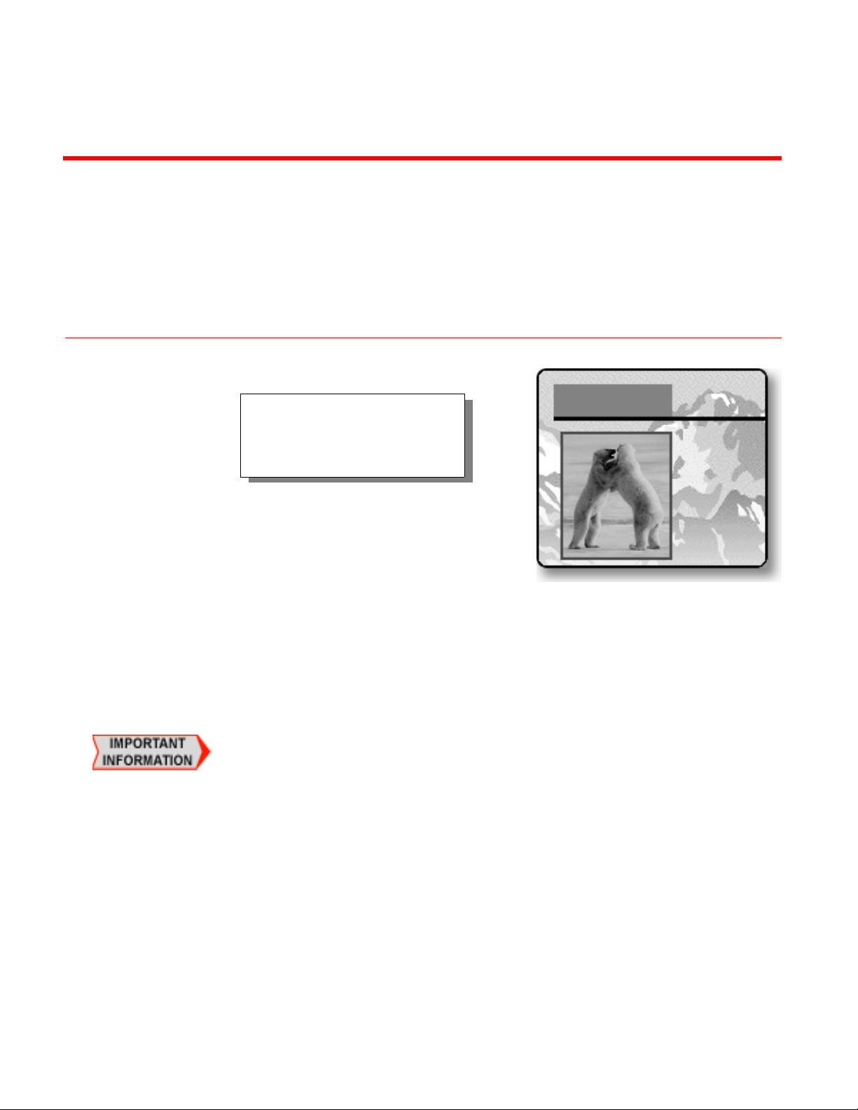
A composition can contain up to four
moving (or still) video tiles, an
unlimited amount of solid color tiles,
and one background.
CHAPTER 9
COMPOSE
Compose provides a way to create screens containing picture elements, solid colors, and
rectangles.
A composed screen consists of a background and one or more objects (called tiles) placed
atop the background. The background fills the entire screen. Tiles can vary in size and
appear anywhere on the screen.
You cannot save composed screens. Therefore, once you set up the composed screen the
way you want it, you must immediately record or display it on the output device. If you
move on to other functions without recording or displaying the composed screen, it is lost
and cannot be recovered.
The MX-4 DV provides a limited set of “drawing tools” in compose mode to help you create
backgrounds and tiles.
Page 94
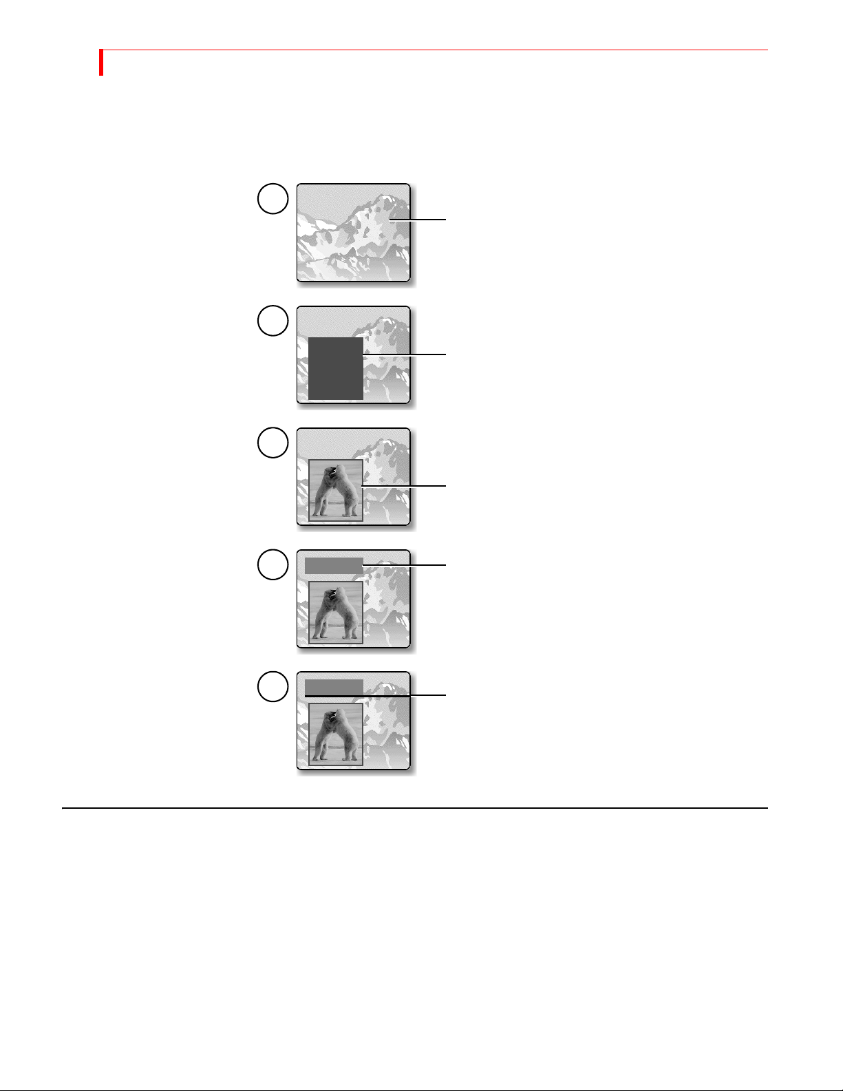
90
MX-4 DV USER GUIDE CHAPTER 9
BASIC COMPOSITION STEPS
This sequence shows how the composition at the beginning of this chapter was produced. More detailed
descriptions of the steps follow.
1
Select the background. This example uses a still image
of a mountain range. You can use imported still jpeg
images, gradients, solid color backgrounds, or color
bars.
2
Create a solid color tile. This rectangle serves as a
background for the next element and separates it
from the main background image.
3
Create the next tile, which is a moving video of two
polar bears jousting.
4
Create another solid colored tile. You might eventually
use this tile as a background for a text title.
BACKGROUNDS
5
The background for a composition can be any of the following:
• A moving video sequence
• A still image (that is, a frozen frame from a video sequence)
• A solid color
• A set of color bars
•A gradient
• An imported still frame jpeg image
Create one last solid color tile, but make it long and thin
so that it looks like a simple, wide line.
Page 95
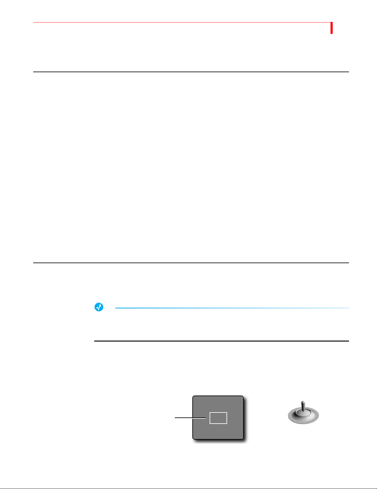
COMPOSE FOREGROUND T ILES
As you’ll learn later in this chapter (under “Creating a Composed Image”), you must establish the
background before entering Compose mode.
FOREGROUND TILES
Creating Color Tiles and Lines
Color tiles can be rectangles of any size and shape.
Colored lines are simply thin rectangles. You can create horizontal and vertical lines, but not diagonal ones.
When you place a color tile on the screen, it can overlap other tiles. If the other tile is a color tile,
the new tile obscures the previous one wherever they overlap. However, if the other tile is a moving video, the color tile does not cover any portion of the moving video.
91
Once you create a color tile you can use
Creating Moving Video Tiles
A tile can contain video originating from any of the MX-4 DV input sources.
The tile can be a rectangle of any size. The MX-4 DV scales the incoming video to fit within the
tile, it does not crop the image.
Creating Still Image Tiles
Still image tiles can contain a frozen image from any of the input sources.
MANIPULATING TILES
You can place foreground tiles anywhere you want on the screen. You can set their size, fill them
with color or images, and set their border characteristics.
TIP
Remember, once you place and define a foreground tile you cannot change it. Placing the tile
occurs once you move the Compose Cursor (or, rectangle) to any other position on the screen.
You’ll learn about the Compose Cursor in this section.
BG COLOR to change its fill color.
Positioning Tiles
When you press the COMPOSE button to enter Compose mode, the MX-4 DV shows your choice of
background on both the Preview and Output monitors. The MX-4 DV also displays a flashing rectangle at the center of the Preview screen. This flashing rectangle is called the Compose Cursor.
The Compose Cursor (a flashing
rectangle) appears on the Preview
screen when you enter Compose
mode.
JOYSTICK positions Compose Cursor
Use the
the
JOYSTICK to move the Compose cursor where you want it on the screen. You can also use
ARROW keys to make fine adjustments.
Page 96
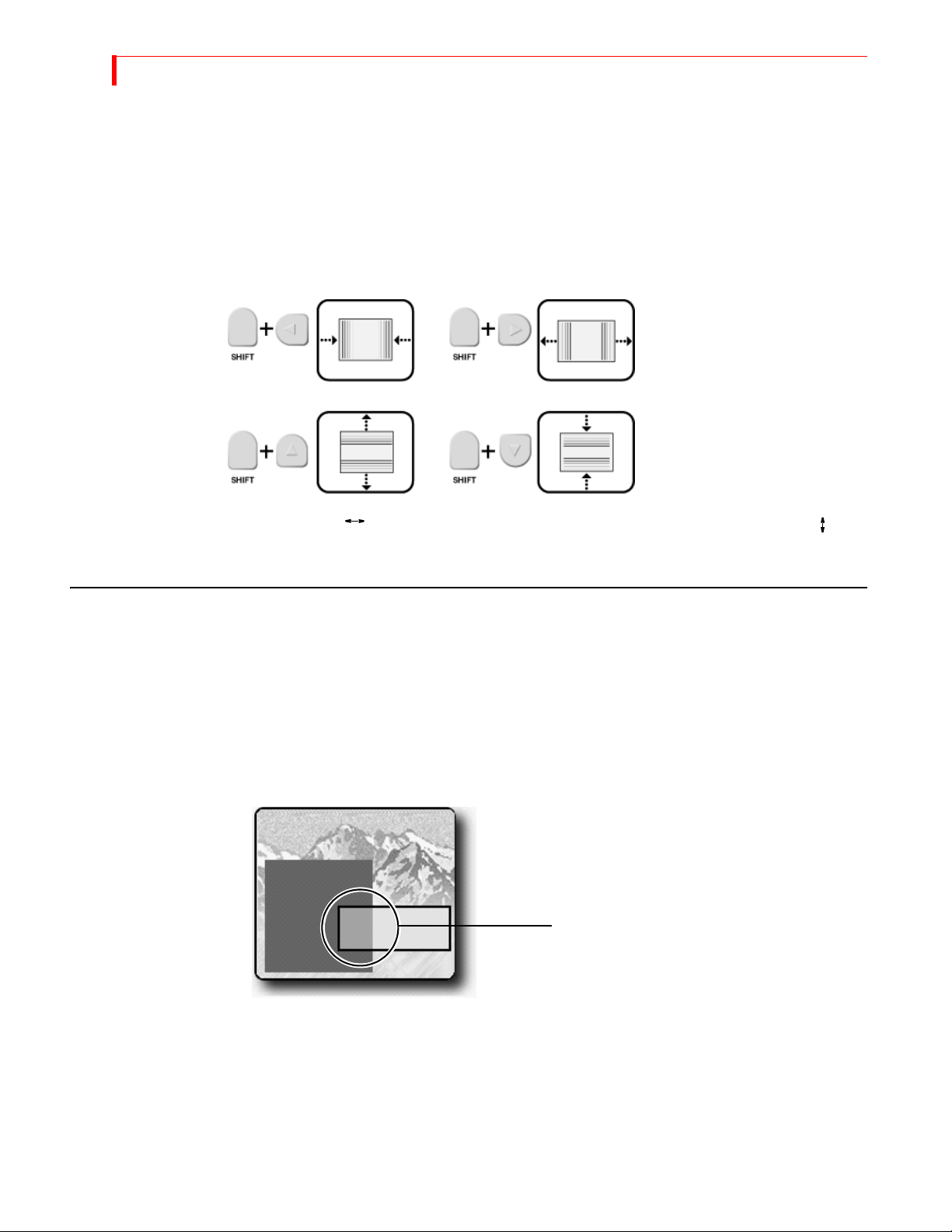
92
MX-4 DV USER GUIDE CHAPTER 9
Sizing Tiles
You can make foreground tiles any size you want, from covering the entire screen to a thin horizontal or vertical line.
Always establish the size of the tile before filling it with a solid color, moving video, gradient, or
jpeg image.
Use the
SHIFT key in conjunction with one of the ARROW keys to adjust tile size. Enter SHIFT+0
(zero) to restore the tile to its default size.
SHIFT+FLIP to reproportion the tile based on its current width. Enter SHIFT+FLIP to
Enter
reproportion the tile based on its current height.
COMPOSITION RULES
Observe the following rules when creating compositions.
• Select and define the image you want to use as the background before entering Compose
mode.
• A composition can contain one background and anywhere from one to four video foreground
tiles with many colors.
• When you create a foreground tile that overlaps an existing solid color rectangle or still image,
the overlapping portion erases whatever it overlaps.
The larger tile is drawn first. When the
second tile is drawn, it overlaps part of the
larger one. The overlapping portion of the
smaller tile erases that portion of the
larger tile where the two overlap.
• Reducing the size of a still or moving video image normally introduces minor pixel artifacts,
thus reducing quality.
• Once you place (or, stamp) a foreground tile into place, you cannot move or change it.
• To use a composed image, you must record or display it on the output. There is no other way to
save the composition.
• You cannot use composed screens in conjunction with Learn mode.
Page 97

COMPOSE CREATING A COMPOSED IMAGE
CREATING A COMPOSED IMAGE
To create a composition:
1 Create or choose the background, foreground, gradient, or still frame jpeg image on the Route
screen. Do this before entering Compose mode because the CURRENT source at the time you
enter compose mode automatically becomes the background for the composition.
93
a Solid Color Background – Use the
CUT/BACKGROUND or use a transition to make BACKGROUND the CURRENT
press
BG COLOR button to select the color you want. Then
source.
b Moving Video Sequence – Use the appropriate
CUT button to make the desired input
source the CURRENT one. For example, to use a moving video sequence from source C
as the background, press
CUT/C.
c Still Image – Use the appropriate CUT button to make the desired input source the CUR-
RENT one. For example, to use a frame from source B as the background, press
When the frame you want to use as the still image appears on the Preview screen, press
FREEZE to create the still image.
d Color Bars – Press SHIFT+NEXT/BACKGROUND while in Compose mode to display color
bars in the background.
e Input Effects – Apply any Input Effects you want to the background source before enter-
ing Compose mode.
f Gradient or Jpeg – Use the Route menu to choose a gradient or jpeg and then route it to a
source. Next press the
CUT key associated with that source to make the gradient or jpeg
the background.
2 Press
COMPOSE to enter Compose mode.
A full screen image of the CURRENT source (the one on the Output) replaces the Preview
screen. The Compose Cursor appears on the Preview screen.
CUT/B.
TIP
To use color bars as the background, enter SHIFT+NEXT/BACKGROUND now – before creating
foreground tiles.
3 Use the JOYSTICK or ARROW KEYS to position the Compose Cursor where you want it on the
screen.
4 Size the Compose Cursor to the size you want for the foreground tile.
You can do the two preceding steps in either order.
5 Press one of the
a Solid Color Background – Press
NEXT buttons to fill the tile with whatever color or image you want.
NEXT/BACKGROUND to fill the tile with the currently
selected color.
To specify a different color from the one currently selected, press
BG COLOR until the
color you want fills the tile.
To create a custom color for the tile, press
T-BAR to create a new color. Press OK when the tile color is the one you want.
b Moving Video Sequence – Press the appropriate
LEARN+BG COLOR, then use the JOYSTICK and
NEXT button to select source A, B, C, or
D. If the dimensions of the tile and video do not match, the video appears distorted.
c Frozen Image – Fill the moving video tile with the image you want, then press
FREEZE.
Page 98

94
MX-4 DV USER GUIDE CHAPTER 9
6 Repeat steps 3 through 5 until your composition is complete.
7 Use the
PLAY button or T-BAR to send your composition to the program output.
PLAYING THE COMPOSITION
To play a composition on the output device:
• Press
Pressing
T-BAR produces a dissolve. Pressing PLAY or using the T-BAR again lets you switch back and forth
between the CURRENT source and the composed image.
To reposition the
rarily disables the
PLAY or use the T-BAR.
Moving the T-BAR from the bottom-to-top in its slot transitions the composition to Program.
Moving it from top-to-bottom dissolves it out.
PLAY produces a cut from the CURRENT source to the composed screen — using the
T-BAR, hold down SHIFT while moving it. Holding down the SHIFT button tempo-
T-BAR.
NOTE
If you cut to any source or exit from Compose mode, your composed screen will be lost and cannot
be recovered.
EXITING FROM COMPOSE MODE
Remember, if you do not record your composed image to the output device before exiting Compose mode, your composed image will be lost and cannot be recovered.
To exit from Compose mode, press
COMPOSE.
Page 99
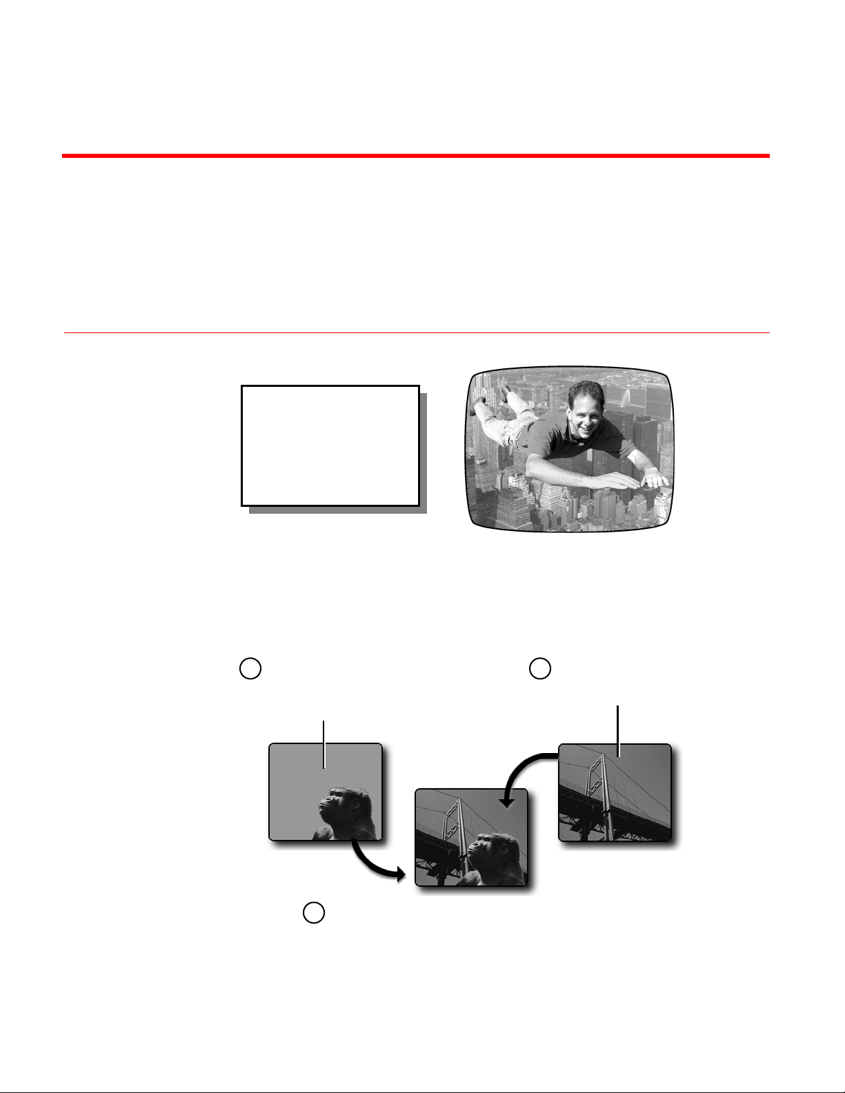
CHAPTER 10
CHROMAKEY
Using Chromakey you can
combine two completely
separate images to create a
composite image that might
be impossible to create any
other way.
You’ve probably seen the chromakey effect used in television weather reports. The weather
person stands in front of a “blue screen” (a solid blue background) and the weather map then
keys onto the background from some other source.
Chromakey combines two sources to create a composite image.
One source has a
1 2
solid colored
background, such as
a blue screen.
The chromakey effect replaces the solid colored
3
background in the first image with the video
signal from the second image. The second image
replaces the background only where the
designated color appears.
Chromakey requires careful preparation of the input sources to achieve the desired effect.
Keep the following points in mind:
The other source
can be any video
image.
Page 100
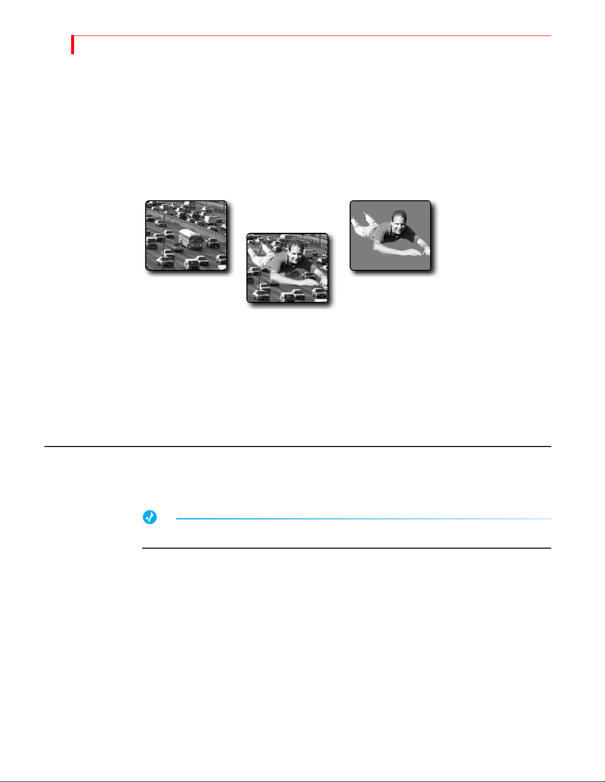
96
MX-4 DV USER GUIDE CHAPTER 10
• The color used for the background must not appear elsewhere in the image. For example, if
Kong’s head (in the example above) contains colors close to the chromakey background, the
picture of the bridge would appear in those areas. (Professionals often use a special “blue
screen” paint for the backdrop when filming the image.)
• The color of the background must be evenly distributed. Glare from camera lights and shadows of the subject can alter the background color. MX-4 DV’s chromakey circuitry might not
be able to handle the different values, thereby spoiling the illusion.
This chapter explains how to prepare footage for use with the chromakey feature. Of course, screen
images appear in grayscale in this book.
Background
Footage
Chromakey
Footage
The Background footage shows traffic moving along a freeway or highway.
The Keyed footage, specially prepared, shows our intrepid hero flying against a solid colored
background.
The Chromakey footage is the result of combining the background footage and keyed footage
using the MX-4 DV chromakey feature.
PREPARING THE BACKGROUND FOOTAGE
Preparation of the background footage does not require anything special. It might be footage of
automobile traffic taken from a bridge.
TIP
The more unusual or dramatic the Background footage the greater the final effect of the chromakey.
Keyed
Footage
 Loading...