

Page 1
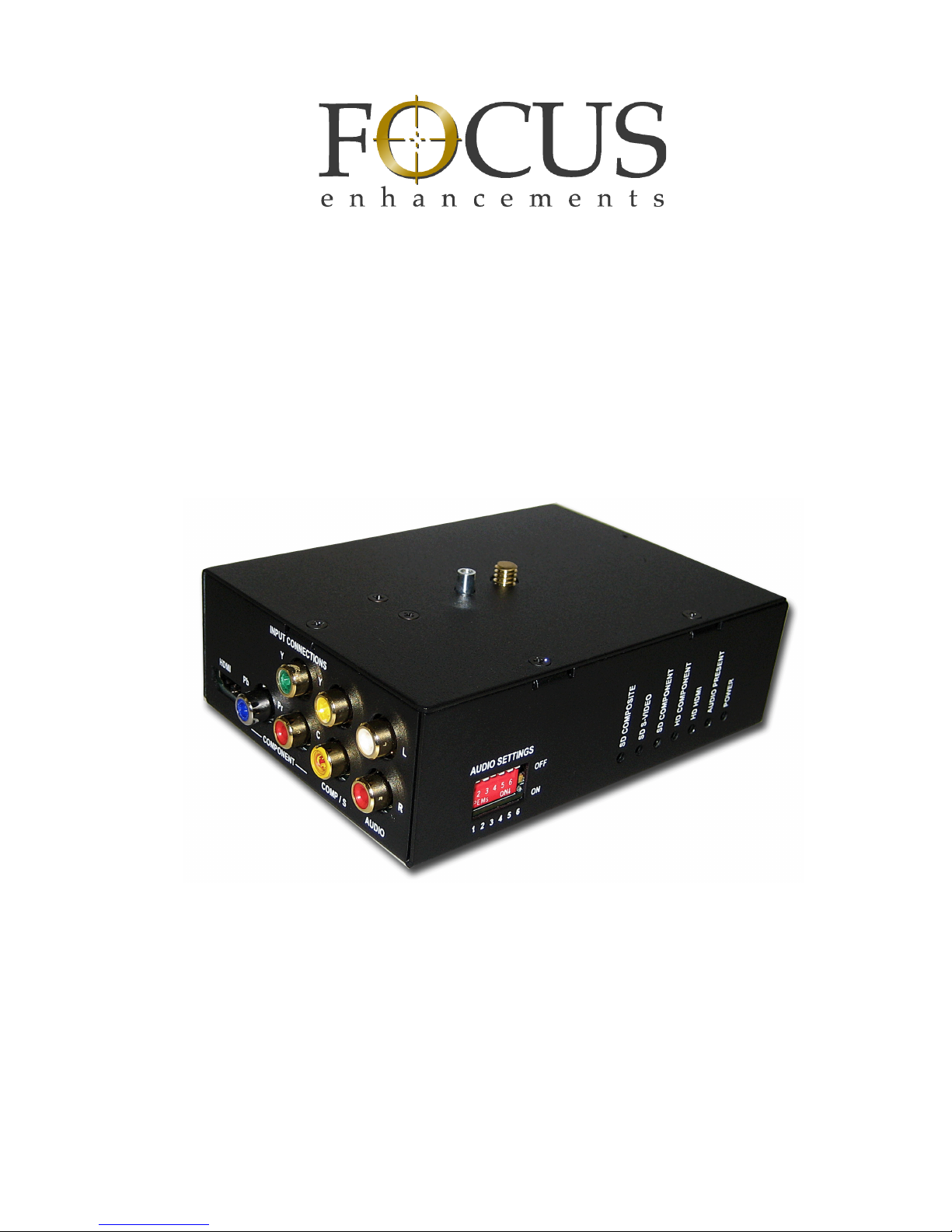
MCSDI-1
Portable SD/HD-SDI
Media Converter
User Guide
MANL-1101-04
Page 2

Page 3

MCSDI-1 Portable SD/HD-SDI Media Converter
i
LEGAL NOTICES
THIS DOCUMENT CONTAINS CONFIDENTIAL AND TRADE
SECRET INFORMATION OF FOCUS ENHANCEMENTS AND
ITS RECEIPT OR POSSESSION DOES NOT CONVEY ANY
RIGHTS TO REPRODUCE OR DISCLOSE ITS CONTENTS, OR
TO MANUFACTURE, USE, OR SELL ANYTHING THAT IT MAY
DESCRIBE. USE IN WHOLE OR IN PART WITHOUT THE
SPECIFIC WRITTEN AUTHORIZATION OF FOCUS
ENHANCEMENTS IS STRICTLY FORBIDDEN.
EVERY EFFORT HAS BEEN MADE TO ENSURE THAT THE
INFORMATION IN THIS DOCUMENT IS COMPLETE AND
ACCURATE AT THE TIME OF PRINTING; HOWEVER, THE
INFORMATION CONTAINED IN THIS DOCUMENT IS SUBJECT
TO CHANGE.
Copyright 2007 Focus Enhancements
All Rights Reserved
The material contained in this document is also protected by
copyright laws of the United States of America and other
countries. It may not be reproduced or distributed in any form by
any means, altered in any fashion, or stored in a data base or
retrieval system, without express written permission of FOCUS
ENHANCEMENTS.
FOCUS ENHANCEMENTS cannot be responsible for
unauthorized use of equipment and will not make allowance or
credit for unauthorized use or access.
Page 4

MCSDI-1 Portable SD/HD-SDI Media Converter
ii
Contacting FOCUS ENHANCEMENTS:
Serial Number
The serial number for this equipment is located on the bottom of
the unit.
USA
Office Hours: Monday through Friday
8:00 AM to 5:00PM (Central Time)
Email: [email protected]
Telephone: +1 763-398-1658
Fax: +1 763-571-7688
Address: Focus Enhancements, Inc.
1370 Dell Avenue
Campbell, CA. 95008
www.focusinfo.com
EMEA (Europe, Middle East, Africa)
Office Hours: Monday through Friday
9:00 AM to 5:00PM
Email: [email protected]
Telephone: +49 4307 - 83 58 58
Fax: +49 4307 - 83 58 99
Address: COMO Computer & Motion GmbH
A Focus Enhancements Company
Lise-Meitner-Str. 15
24223 Raisdorf / Germany
www.focusinfo.com
Page 5

MCSDI-1 Portable SD/HD-SDI Media Converter
iii
Regulations and Safety
FCC Class A
This product satisfies FCC regulations when shielded cables
and connectors are used to connect the unit to other equipment.
To prevent electromagnetic interference with electric appliances
such as radios and televisions, use shielded cables and
connectors.
This equipment has been tested and found to comply within the
limits for a Class A digital device, pursuant to Part 15 of the
FCC Rules. These limits are designed to provide reasonable
protection against harmful interference in an office or industrial
installation. This equipment generates, uses, and can radiate
radio frequency energy and, if not installed and used in
accordance with the instructions, may cause harmful
interference to radio communications. However, there is no
guarantee that interference will not occur in a particular
installation. If this equipment does cause harmful interference to
radio or television reception, which can be determined by
turning the equipment off and on, correct the interference by
one or more of the following:
• Reorient or relocate the receiving antenna.
• Increase the separation between the equipment and
receiver.
• Connect the equipment to an outlet on a circuit different
from that used by the receiver.
• Consult the dealer or an experienced radio/TV technician
for help.
Focus Enhancements, Inc.
1370 Dell Avenue
Campbell, CA. 95008
Model Number: MCSDI-1 Portable SD/HD-SDI
Media Converter
Date of Manufacture:
Reference the Serial Number label attached to
the unit.
Page 6

MCSDI-1 Portable SD/HD-SDI Media Converter
iv
Compliance
MCSDI-1 is a device marketed for use in industrial or business
environments. The MCSDI-1 complies with the regulations the
following testing agencies:
Australia and New Zealand
European Union
Page 7

MCSDI-1 Portable SD/HD-SDI Media Converter
v
Safety
Symbols
In the MCSDI-1 Documentation
Documentation
Read, Retain, and Follow Instructions
All the safety and operating instructions should be read before
the product is operated.
• Retain Documentation
Place documentation in a secure place for future reference on
operating and safety instructions.
• Follow All Operating and Safety Instructions
• Pay Attention to All Warnings
Warnings are provided to protect the operator, the equipment,
and content.
Caution Title
This symbol indicates important operating or maintenance (servicing)
information that the user should read and understand.
Note Title
This symbol indicates supplementary information about features, functions, or operations that may be of interest to the user.
Page 8

MCSDI-1 Portable SD/HD-SDI Media Converter
vi
Electrical Precautions
Do Not Expose to Moisture
Do not use this product near water or in an environment where it
is exposed to dampness or there is the possibility of it getting wet.
Do Not Remove Cover
There are No User Serviceable Parts inside this unit. Servicing
should be done by qualified service personnel.
Power Sources
Use only power sources that match those indicated on the
marking label. If unsure sure of the type of power supply that is
available, consult your dealer or local power company.
Do Not Overload Power Outlets
Do not overload wall outlets, extension cords, or integral
convenience receptacles as this can result in a risk of fire or
electric shock.
Verify Power Plugs are Fully Inserted
To prevent potential electrical shock to personnel, verify that the
MCSDI-1 power cord plug is fully inserted in to a grounded
receptor and that the plug blades are not exposed.
ATTENTION
POUR PREVENIR LES CHOCS ELECTRIQUES NE PAS
UTILISER CETTE FICHE POLARISEE AVEC UN
PROLONGATEUR, UNE PRISE DE COURANT OU UNE AUTRE
SORTIE DE COURANT, SAUF SI LES LAMES PEUVENT ETRE
INSEREES A FOND SANS EN LAISSER AUCUNE PARTIE A
DECOUVERT.
Page 9

MCSDI-1 Portable SD/HD-SDI Media Converter
vii
Power-Cord Protection
• Routing Power-Cords
Route power supply cords so that they are not likely to be
walked on or pinched by items placed upon or against them.
Avoid sharp angles in the cord, particularly at plugs,
convenience receptacles, and the point where they exit the
product.
• Non-Use Period
During extended periods when the device is not used, unplug
it from the power source and retract the power-cord.
Grounding or Polarization
• Polarized
If this product is equipped with a polarized alternating current
line plug (a plug having one blade wider than the other), it will
fit into the outlet only one way. This is a safety feature. If you
are unable to insert the plug fully into the outlet, try reversing
the plug. If the plug should still fail to fit, contact your
electrician to replace your obsolete outlet. Do not defeat the
safety purpose of the polarized plug.
• Grounded
If this product is equipped with a three-wire grounding type
plug, a plug having a third (grounding) pin, it will only fit into a
grounding type power outlet. This is a safety feature. If you
are unable to insert the plug into the outlet, contact your
electrician to replace your obsolete outlet. Do not defeat the
safety purpose of the grounding type plug.
Page 10
MCSDI-1 Portable SD/HD-SDI Media Converter
viii
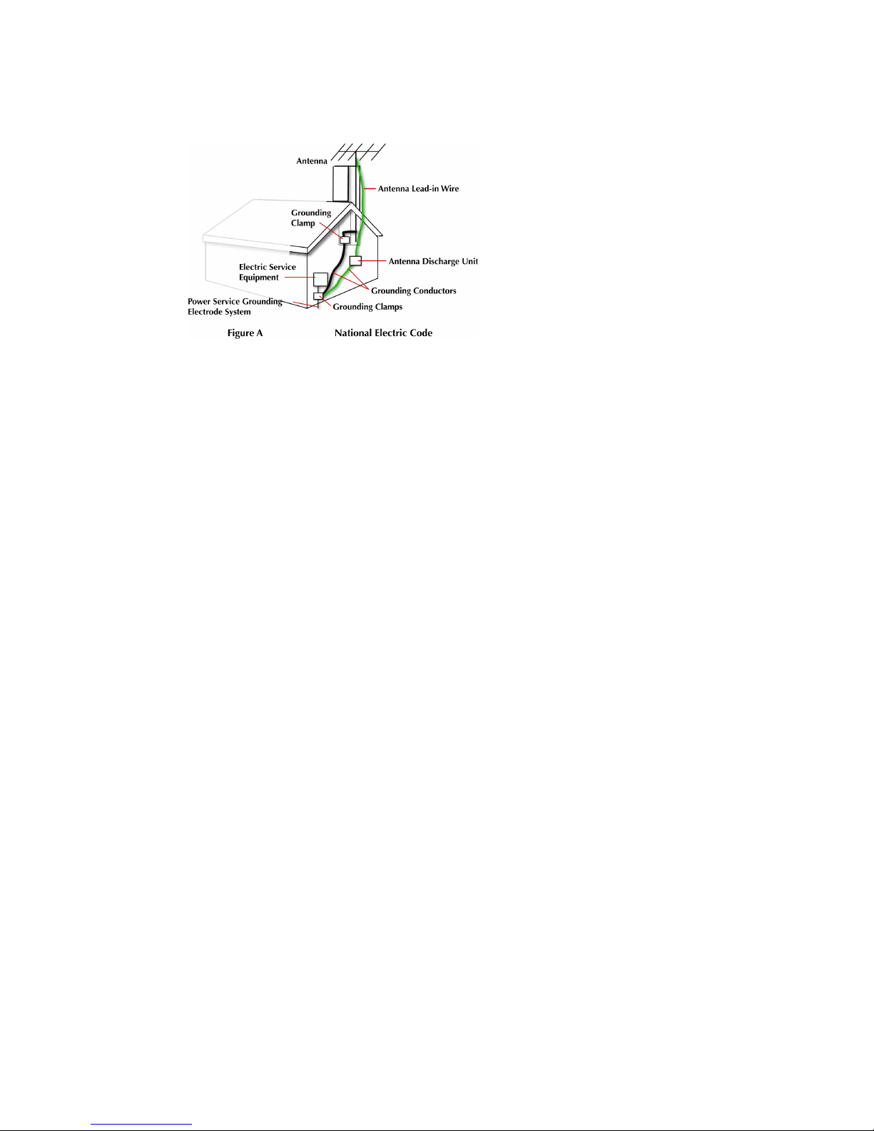
Outdoor Antenna Grounding
If an outside antenna
or cable system is
connected to the
MCSDI-1, verify that
the antenna or cable
system is grounded.
This provides some
protection against
voltage surges and
built-up static charges.
Refer to Article 810 of
the National Electric Code, ANSI/NFPA 70, for information about
the proper grounding of the mast and supporting structure,
grounding of the lead-in wire to an antenna discharge unit, size of
grounding connectors, location of antenna discharge unit,
connection to grounding electrodes, and requirements for the
grounding electrode.
Ground Loop WARNING:
To avoid earth or ground loops, insure that all equipment
connected to the MCSDI-1 share a common ground. Use a
single, grounded outlet strip as opposed to separate outlets with
the possibility of different ground potentials.
Lightning and Power Surges
During electrical storms or when left unattended and unused for
long periods of time, unplug the MCSDI-1 from the power source
and disconnect the antenna or cable system.
Power Lines
Do not locate an outside antenna system in the vicinity of
overhead power lines, electric light or power circuits, or where it
can fall onto such lines or circuits.
When installing an outside antenna system, extreme care should
be taken to keep from touching such power lines or circuits as
contact with them might be fatal.
Optical Precaution
The use of optical instruments with this device will increase
hazards to the eyes hazard.
Page 11

MCSDI-1 Portable SD/HD-SDI Media Converter
ix
Maintenance and Moving
Cleaning
Unplug this product from the wall outlet before cleaning. The
product should be cleaned only with a polishing cloth or a soft dry
cloth. Never clean with furniture wax, benzine, insecticides or
other volatile liquids since they may corrode the cabinet.
Servicing
Unplug the device from the power outlet and refer servicing to
qualified service personnel under the following conditions:
• When the power-supply cord or plug is damaged.
• If liquid has been spilled, or objects have fallen into the
product.
• If the product has been exposed to rain or water.
• If the product does not operate normally when following the
operating instructions. Adjust only those controls that are
covered by the operating instructions. The incorrect
adjustment of other controls can result in damage and often
requires extensive work by a qualified technician to restore the
product to its normal operation.
• If the product has been dropped or damaged in any way.
• When the product exhibits a distinct change in performance.
Accessories and Replacement Parts
Use only attachments and accessories recommended by Focus
Enhancements.
Use only replacement parts specified by the Focus
Enhancements or of comparable quality and characteristics as
the original parts.
Unauthorized substitution of parts can result in fire, electrical
shock, other hazards, and loss of warranty.
Safety Check
Upon completion of any service or repairs to this product, ask the
service technician to perform safety checks to determine that the
product is in proper operating condition.
Page 12

MCSDI-1 Portable SD/HD-SDI Media Converter
x
Operating Environment
Location
Any mounting of this device should follow its instructions, and
should use only mounting accessories recommended by Focus
Enhancements.
• Install this device on a sturdy, level surface, away from
moisture and dust.
• Heat
Locate this device away from heat sources such as radiators,
heat registers, stoves or other electrical devices (including
amplifiers) that generate heat.
Ventilation
Do not block the ventilation openings in the MCSDI-1 cabinet.
Overheating can occur and damage the device. Do not place this
device in a built-in installation, such as a bookcase or rack,
unless proper ventilation is provided.
Page 13

MCSDI-1 Portable SD/HD-SDI Media Converter
xi
Table of Contents
Unpacking the MCSD-1 . . . . . . . . . . . . . . . . . . . . . . . . . . .1
Introduction . . . . . . . . . . . . . . . . . . . . . . . . . . . . . . . . . . . .3
Input Connectors (Back) . . . . . . . . . . . . . . . . . . . . . . . . . . . 4
Audio . . . . . . . . . . . . . . . . . . . . . . . . . . . . . . . . . . . . . . 4
Video . . . . . . . . . . . . . . . . . . . . . . . . . . . . . . . . . . . . . . . 4
Output and Power Connectors (Front) . . . . . . . . . . . . . . . . 6
Output Connector . . . . . . . . . . . . . . . . . . . . . . . . . . . . 6
Power Connector . . . . . . . . . . . . . . . . . . . . . . . . . . . . . 6
Audio and Status LEDs (Side) . . . . . . . . . . . . . . . . . . . . . . . 7
Audio Switch Settings . . . . . . . . . . . . . . . . . . . . . . . . . . 7
Status LEDs . . . . . . . . . . . . . . . . . . . . . . . . . . . . . . . . . 8
Camera Mounting (Top) . . . . . . . . . . . . . . . . . . . . . . . . . . . 9
Tripod Mount (Bottom) . . . . . . . . . . . . . . . . . . . . . . . . . . . . 9
Using the MCSDI-1 . . . . . . . . . . . . . . . . . . . . . . . . . . . . . 11
Studio . . . . . . . . . . . . . . . . . . . . . . . . . . . . . . . . . . . . . . . . 12
Typical Analog Studio . . . . . . . . . . . . . . . . . . . . . . . . . 12
Digital SDI Studio . . . . . . . . . . . . . . . . . . . . . . . . . . . . 12
Setup with Camera . . . . . . . . . . . . . . . . . . . . . . . . . . . . .13
Mounting Video Camera to the MCSDI-1 . . . . . . . . . . . . . 14
Securing Assembly to Tripod . . . . . . . . . . . . . . . . . . . . . . 15
Connecting Camera to MCSDI-1 . . . . . . . . . . . . . . . . . . . 16
Using the Cable Tie Kits . . . . . . . . . . . . . . . . . . . . . . 17
Connecting MCSDI-1 to Studio and Power . . . . . . . . . . . . 18
Test Signal . . . . . . . . . . . . . . . . . . . . . . . . . . . . . . . . . . . . . 18
Operating Conditions and Warranty . . . . . . . . . . . . . . . . 19
Operating Conditions . . . . . . . . . . . . . . . . . . . . . . . . . . . . 19
Temperature . . . . . . . . . . . . . . . . . . . . . . . . . . . . . . . . 19
Warranty . . . . . . . . . . . . . . . . . . . . . . . . . . . . . . . . . . . . . . 19
Page 14

Page 15
MCSDI-1 Portable SD/HD-SDI Media Converter
1
Unpacking the MCSD-1
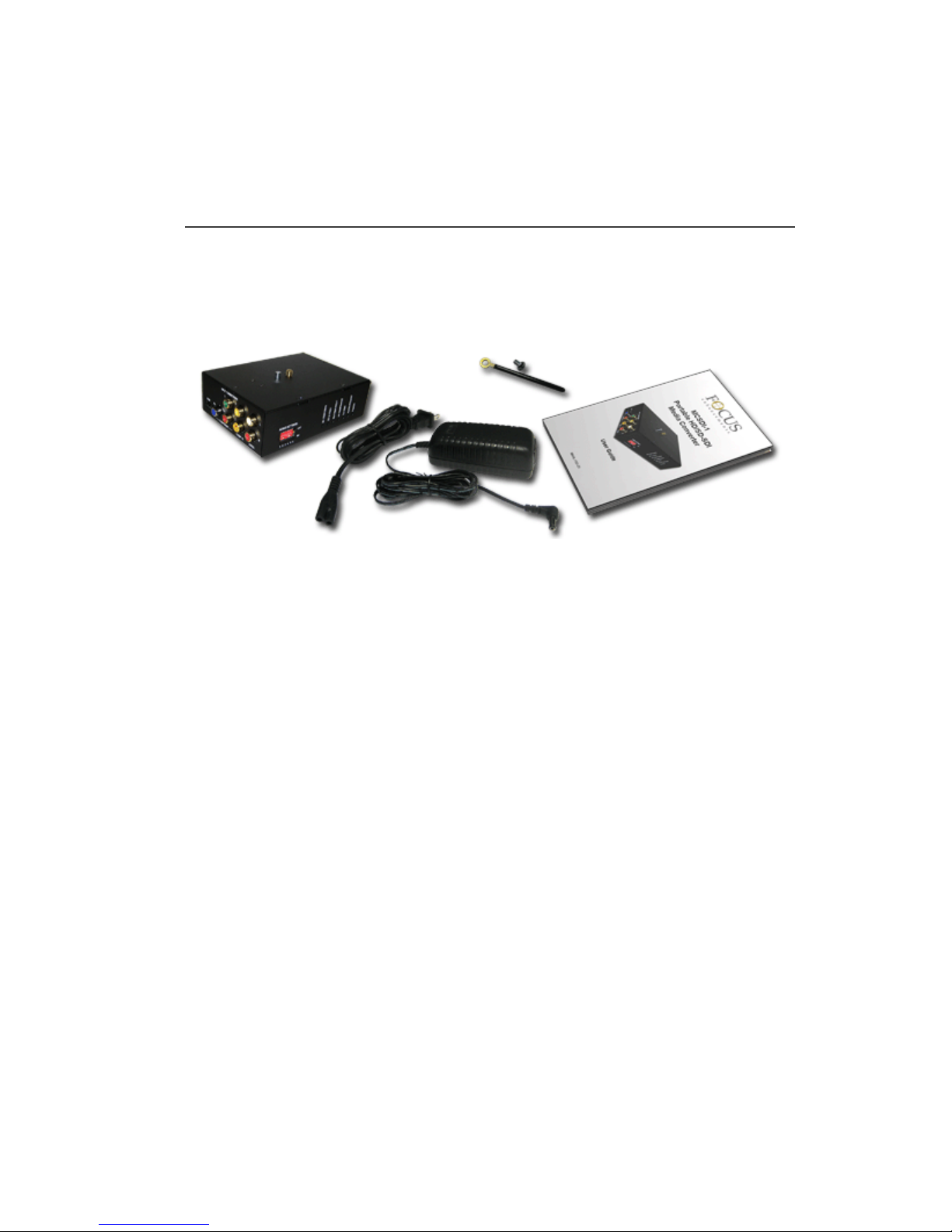
Verify that the MCSDI-1 has the following items:
These optional components are available for purchase from
your local dealer or online at the Focus Enhancements web
store,
www.focusinfo.com/webstore.
Component Part Number Qty.
1. MCSDI-1 Portable Media Converter MCSDI-1 1
2. AC Adapter (15V, 1.2A) and
IEC Power Cable
PWRS-0038-xx 1
3. Cable Routing Kits (one kit shown) ASYS-0609-xx 2
4. User Guide, MCSDI-1 MANL-1101-xx 1
Optional Accessories or Companion Devices
HX-1 Portable Video Switcher
HX-1
HDMI cable, short CBLA-0162-xx
1
2
3
4
Page 16

MCSDI-1 Portable SD/HD-SDI Media Converter
2
Missing or Damaged Components
If there are missing or damaged items, contact Focus Enhancements
Support for assistance.
USA Email: [email protected]
USA Telephone: +1 763-398-1658
EMEA Email: [email protected]
EMEA Telephone: +49 4307 - 83 58 58
Page 17
MCSDI-1 Portable SD/HD-SDI Media Converter
3
Introduction
Thank you for purchasing a Focus Enhancements MCSDI-1 Portable
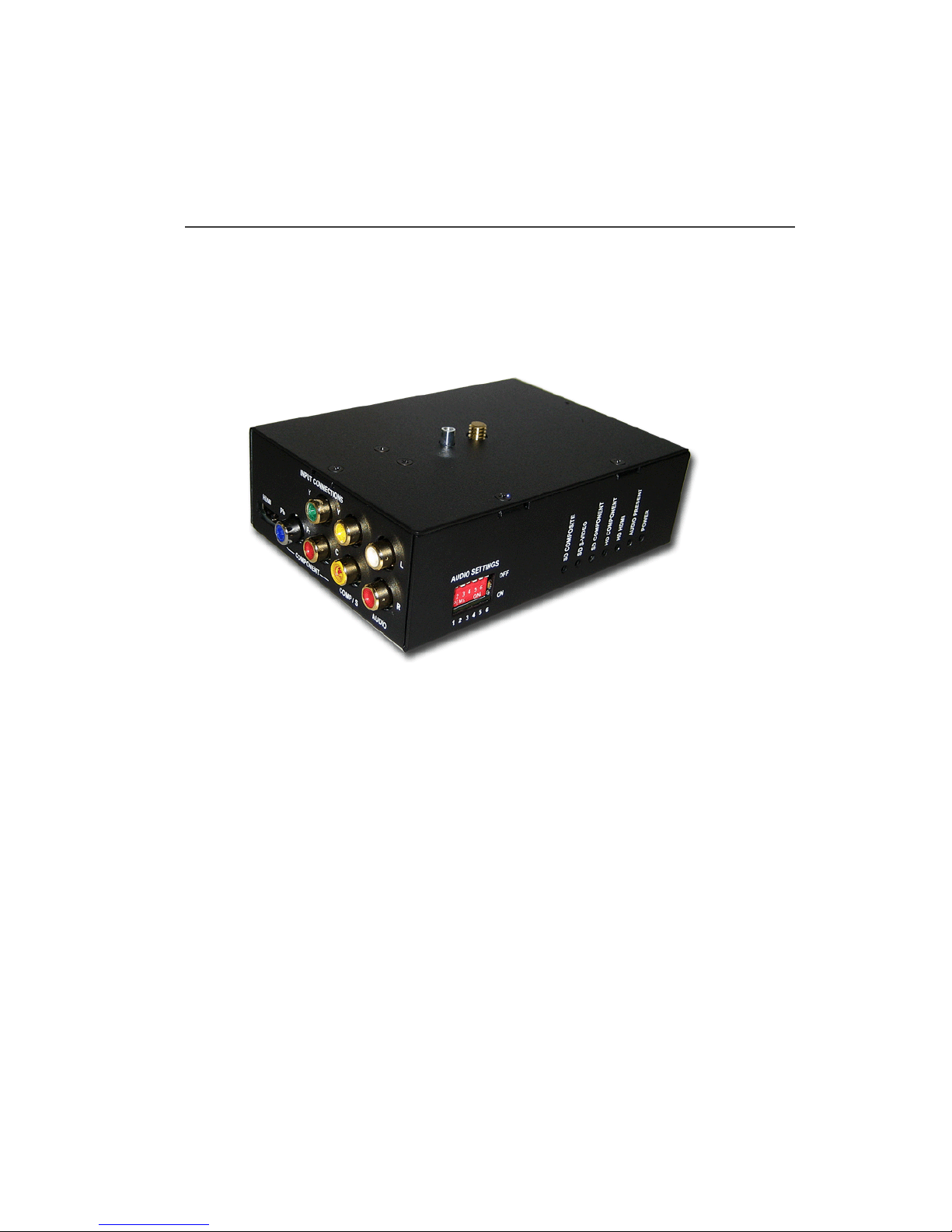
SD/HD-SDI Media Converter. The MCSDI-1 is a compact, standalone media converter that automatically determines the type of
HDMI, component, and Y/C (composite) input and outputs either an
HD-SDI or SD-SDI stream, depending on the type of input.
Input Connectors
Audio Settings Switches
Status LEDs
Camera Mount Hardware
Output Connector
Power Connector
(Not Shown)
Tripod Mount Hardware
(not shown)
Page 18
Introduction
MCSDI-1 Portable SD/HD-SDI Media Converter
4
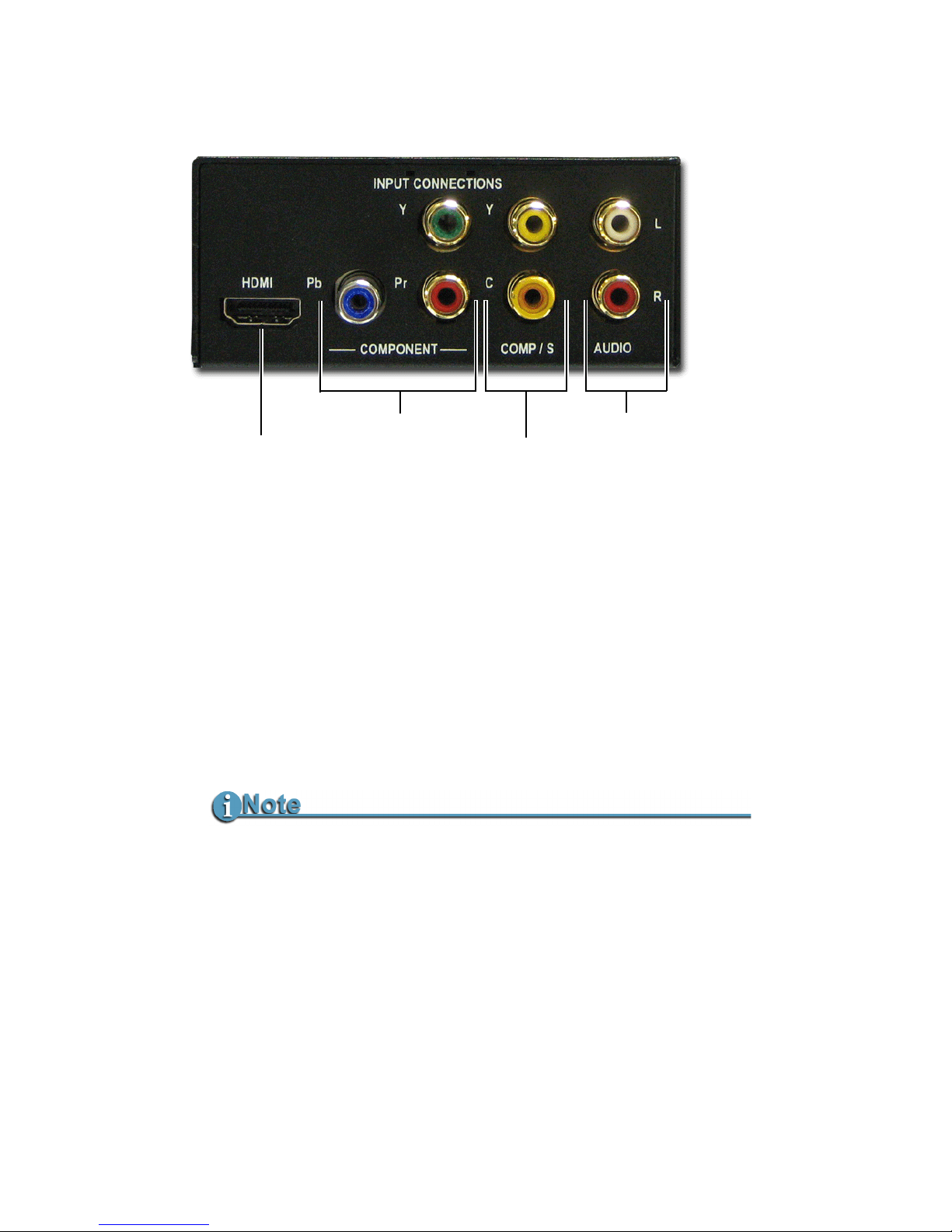
Input Connectors (Back)
Audio
Video
Autosense
The MCSDI-1 is able to automatically sense the type of input and
its resolution and then output the appropriate SDI video signal.
Autosense determines input type in the following order: HDMI,
Component, Y/C, and Composite.
Analog / Digital analog: 24-bits, conversion at 48kHz
digital: 24-bits, 48kHz
Connectors 2 RCA Jacks (2-channel)
SMPTE-299, SMPTE-272M-A
Embedded Audio User selectable audio input levels, see Audio
Switch Settings on page 7.
Analog audio inputs are inactive when HDMI input is used.
HDMI
Component
Y
Pb Pr
Composite
S-Video (Y/C)
Y
C
Audio
L
R
Page 19

Introduction
MCSDI-1 Portable SD/HD-SDI Media Converter
5
Component
Composite / S-Video (Y/C)
HDMI
HD / SD 10-bits
Connectors 3 RCA Jacks, Y Pb Pr,
SMPTE-125M (SD),
SMPTE-274M (HD 1080i),
SMPTE-296M (HD 720p)
Resolution NTSC (480/59.94i)
PAL (576/50i)
1080/59.94i
1080/50i
720/59.94p
720/50p
SD only 10-bits
Connectors 2 RCA Jacks, Y/C,
Y/C 10 bits, SMPTE-125M
Resolution NTSC (480/59.94i)
PAL (576/50i)
Cabling Use a Y/C breakout cable to make the Y/C
connection. A breakout cable connection
permits transmitting the Y and C signals on
separate coaxial cable connections which
permits the use of higher quality cable and
provides longer cable runs.
Connector
Type A, 19-pin HDMI
Resolution 1080/59.94i
1080/50i
Audio Input
48 KHz, 96 KHz or 192 KHz.
Output converted to 48 KHz.
Page 20
Introduction
MCSDI-1 Portable SD/HD-SDI Media Converter
6
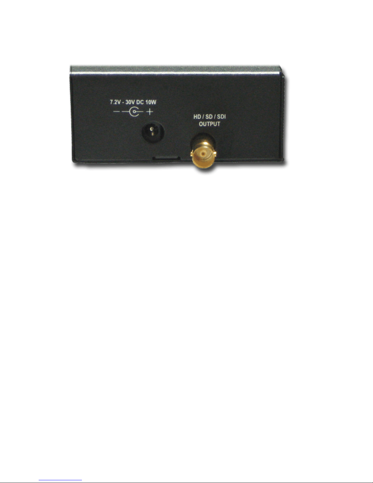
Output and Power Connectors (Front)
Output Connector
Power Connector
SDI Outputs either HD or SD, depending on type of
input, see Autosense on page 4.
Connector 1 BNC, 75 OHM, SMPTE-259/292
Cabling For SD-SDI or HD-SDI, use RG11 cable.
Estimated distances with this cable are:
HD-SDI, 656 ft. (200 m.)
SD-SDI, 1148 ft. (350 m.)
While RJ59 can be used for short distances, it
is not guaranteed.
Audio 20 bit 48 KHz per SMPTE-272M (SD),
24-bit 48KHz per SMPTE-299M (HD)
DC Power input range: 7.2 to 30 Volts DC
AC Adapter AC Adapter (15V, 1.2A) and IEC Power Cable
provided with MCSDI-1, see Unpacking the
MCSD-1 on page 1.
Video Output
Connector
DC Power
Connector
Page 21
Introduction
MCSDI-1 Portable SD/HD-SDI Media Converter
7
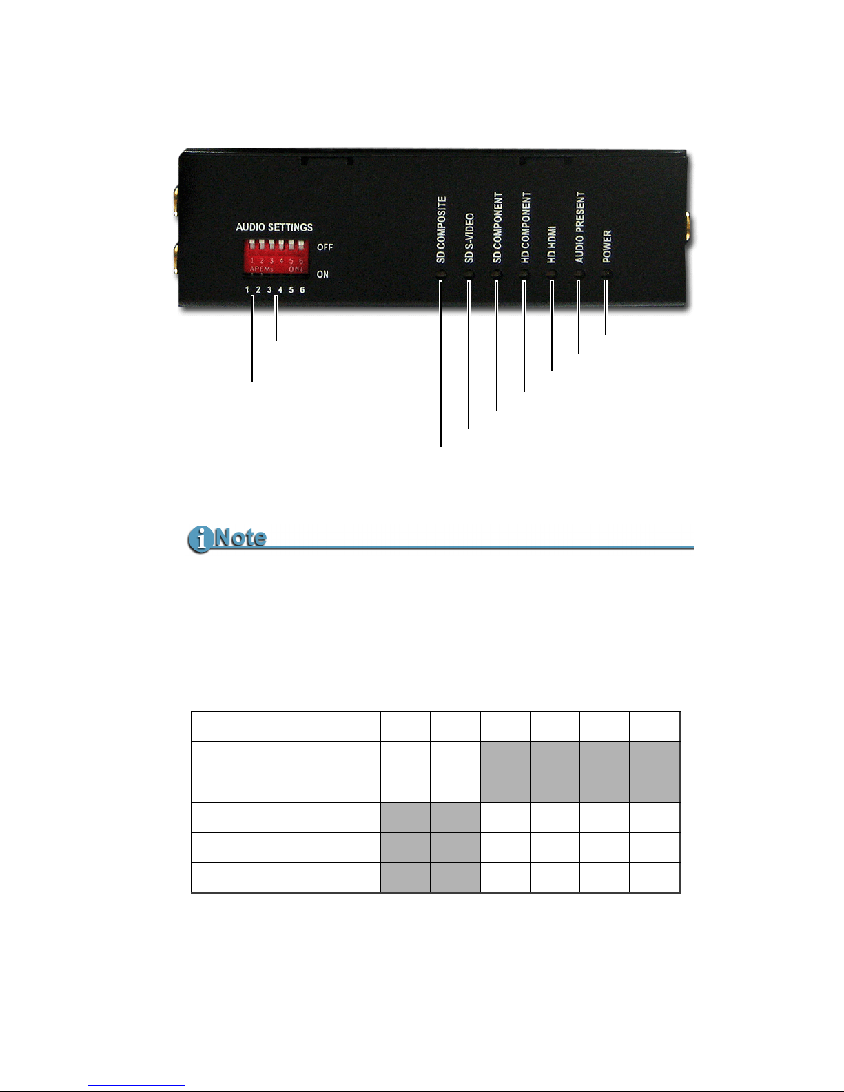
Audio and Status LEDs (Side)
Audio Switch Settings
AUDIO LED Indicates No Audio or Out of Range (Clipping)
When audio is absent or out of range (clipping) the audio LED will be
OFF. When the audio is present and in range the LED is ON. Audio
clipping can be compensated using the Audio switch settings
(below).
Switch Numbers
123456
High Impedance
OFF OFF
Low Impedance (600 Ω)
ON ON
Input Level -8dbu
OFF OFF OFF OFF
Input Level +4dbu
ON ON OFF OFF
Input level 0dbu
OFF OFF ON ON
Power
Audio
HD Component
HD HDMI
SD Component
SD S-Video
SD Composite
Status LEDs
Audio Settings
Input Levels
(3-6)
Impedance
(1-2)
Page 22

Introduction
MCSDI-1 Portable SD/HD-SDI Media Converter
8
Status LEDs
Status LEDs light to indicate when power is ON and which input
stream is active.
Check Camera Documentation For Impedance Requirements
A few cameras require the 600 ohm load and will need the Low
Impedance
input setting. All other cameras use the typical High
Impedance
line input.
Page 23
Introduction
MCSDI-1 Portable SD/HD-SDI Media Converter
9
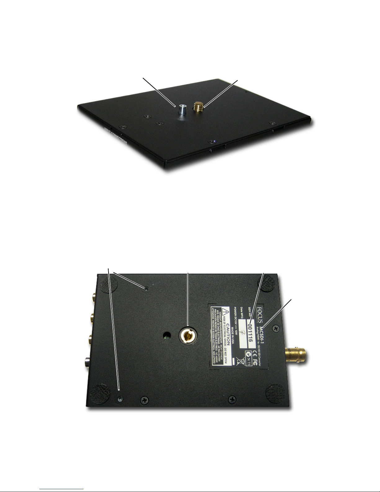
Camera Mounting (Top)
For more information see, Mounting Video Camera to the MCSDI-1 on
page 14.
Tripod Mount (Bottom)
For more information, see Securing Assembly to Tripod
on page 15.
Alignment Pin
Mounting Screw
Camera Mounting Screw
and Tripod Socket
Serial
Number
Model
Cable Retainer
Screw Holes
Page 24

MCSDI-1 Portable SD/HD-SDI Media Converter
10
Page 25
MCSDI-1 Portable SD/HD-SDI Media Converter
11
Using the MCSDI-1
The MCSDI-1 Portable SD/HD-SDI Media Converter provides small
video production organizations with a flexible, low cost method to
upgrade HD camcorders to digital SDI capabilities. The MCSDI-1 is
designed for:
Live Video Production
Broadcasting
Corporate and Industrial Production
Education and Training
Events and Entertainment
Government
Postproduction
Page 26

Using the MCSDI-1
MCSDI-1 Portable SD/HD-SDI Media Converter
12
Studio
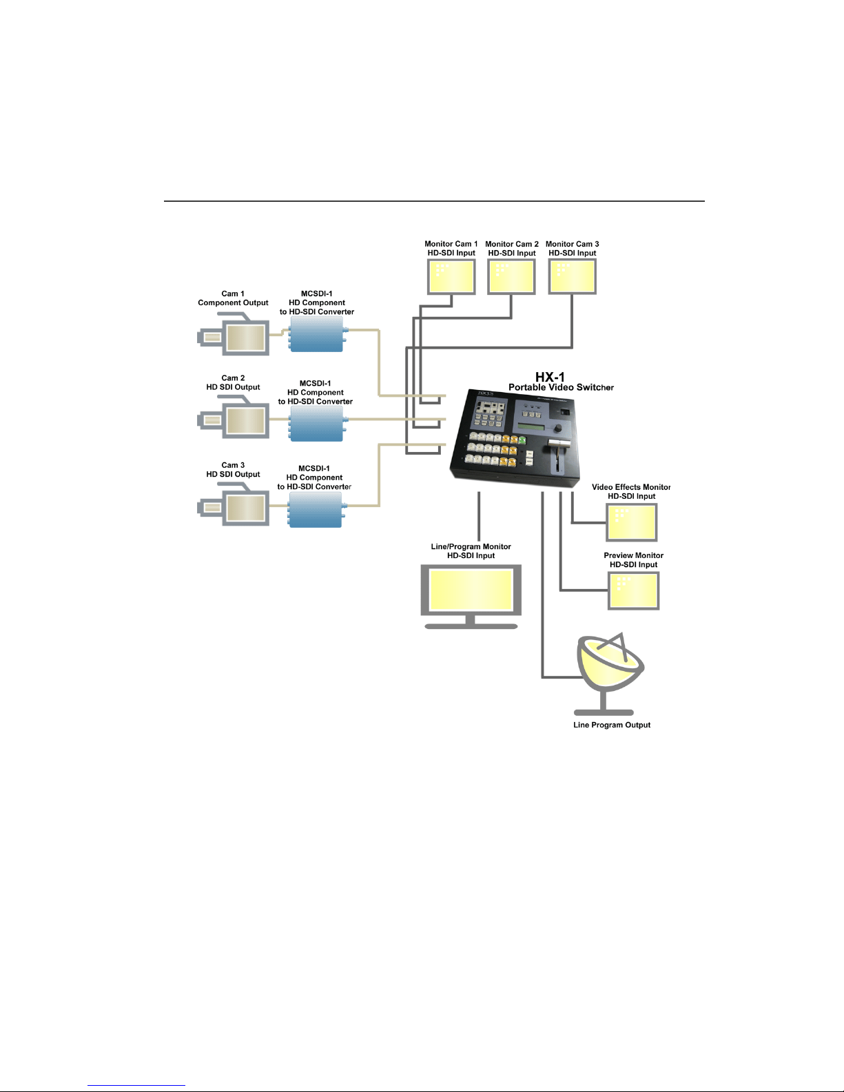
Typical Analog Studio
Typically, small broadcasters cover interviews, presentations, and
live events. The average studio is an analog environment with
three HD or SD cameras. In the studio or field, the short cable
lengths required for analog technology restricts camera placement
in relation to video switchers and mixers.
Digital SDI Studio
SD/HD-SDI is a digital video technology that frees camera
placement in the studio and field. It also prepares the studio for the
use of the latest digital video switchers and mixers.
The MCSDI-1 automatically senses the output from the analog or
digital SD/HD camera and converts it to a corresponding SD/HDSDI digital signal, for more information see
Autosense on page 4.
SDI cabling provides for longer cable runs:
• HD-SDI, 656 ft. (200 m.)
• SD-SDI, 1148 ft. (350 m.)
Page 27

MCSDI-1 Portable SD/HD-SDI Media Converter
13
Setup with Camera
Follow the steps below to:
• Mount a video camera to the MCSDI-1,
• Secure the assembly to a tripod,
• Make necessary connections between the camera and the
MCSDI-1,
• Connect the MCSDI-1 to the studio network.
Page 28
Setup with Camera
MCSDI-1 Portable SD/HD-SDI Media Converter
14
Mounting Video Camera to the MCSDI-1
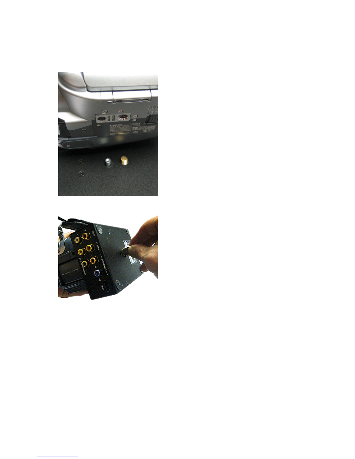
1. Position camera mounting
holes on the bottom of the
camera with the alignment pin
and mounting screw on the top
of the MCSDI-1.
The alignment pin is spring
loaded. If the camera does not
have an alignment hole, the pin
retracts out of the way.
The front of the camera and
MCSDI-1 should point in the
same direction.
2. Thread the MCSDI-1’s
mounting screw into the
camera’s tripod socket.
To turn the mounting screw,
locate the brass head of the
mounting screw on the bottom
of the MCSDI-1. Use a coin or
screwdriver to turn the screw.
This screw also functions as the
MCSDI-1’s tripod socket.
3. Tighten the mounting screw so
that the camera and MCSDI-1
are firmly attached.
Do Not Over Tighten.
Page 29
Setup with Camera
MCSDI-1 Portable SD/HD-SDI Media Converter
15
Securing Assembly to Tripod
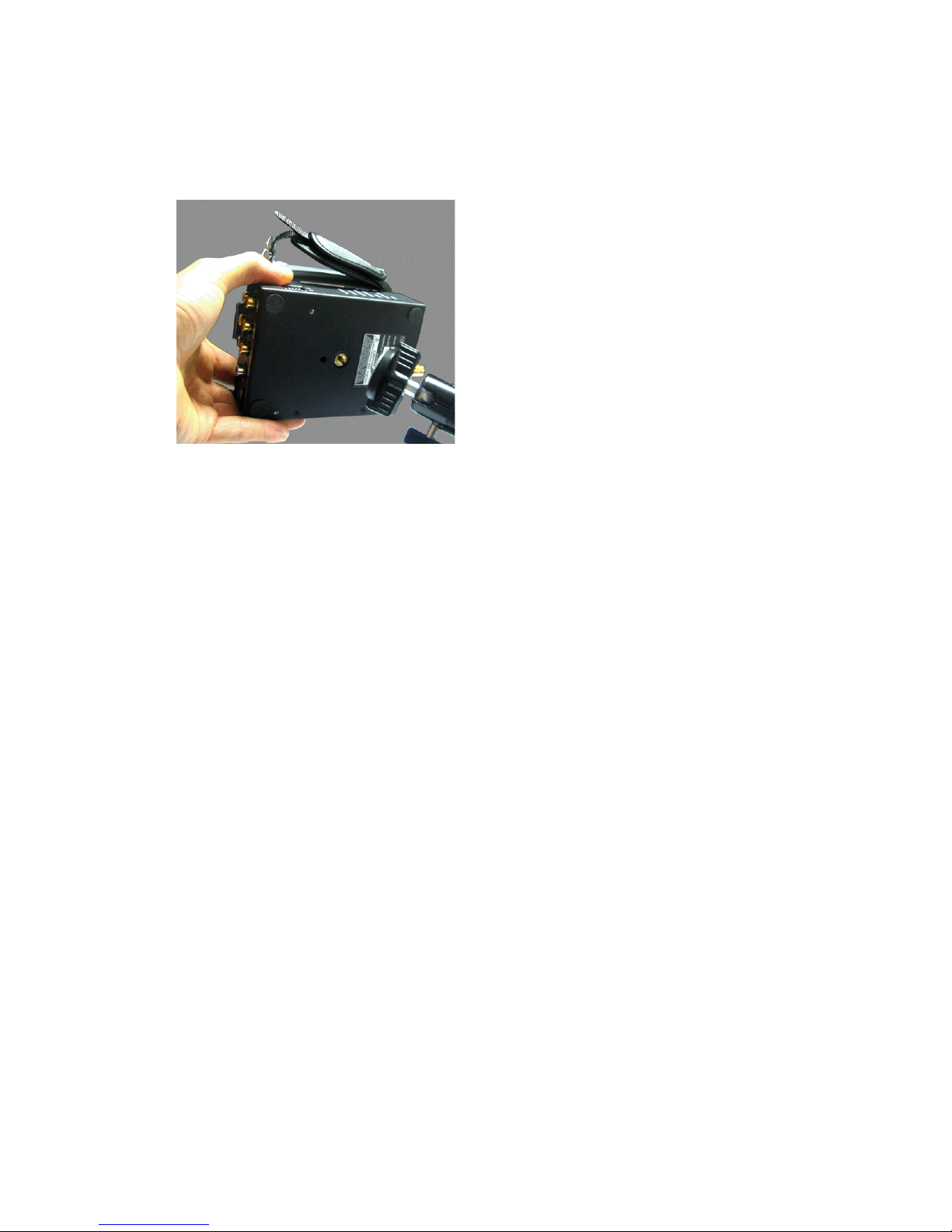
1. Align the tripod’s mounting
screw with the MCSDI-1’s
tripod socket.
This is the brass head of the
camera mounting screw.
2. Thread the tripod’s mounting
screw into the MCSDI-1’s
tripod socket.
3. Tighten the tripod mounting
screw until the MCSDI-1 is
secure.
Do Not Over Tighten.
Page 30
Setup with Camera
MCSDI-1 Portable SD/HD-SDI Media Converter
16
Connecting Camera to MCSDI-1
Connections will depend on the camera being used. Refer to camera
documentation for information about type of video output and
location of connectors.
If the MCSDI-1 does not
automatically detect a new input
type, power-cycle the MCSDI-1
unit.
1. Determine the camera’s type of
video output: SD/HD,
component, composite, or
HDMI.
Do Not Change Input
Connections During
Critical Usage
The SDI output stream is
disrupted when connecting or
disconnecting a device.
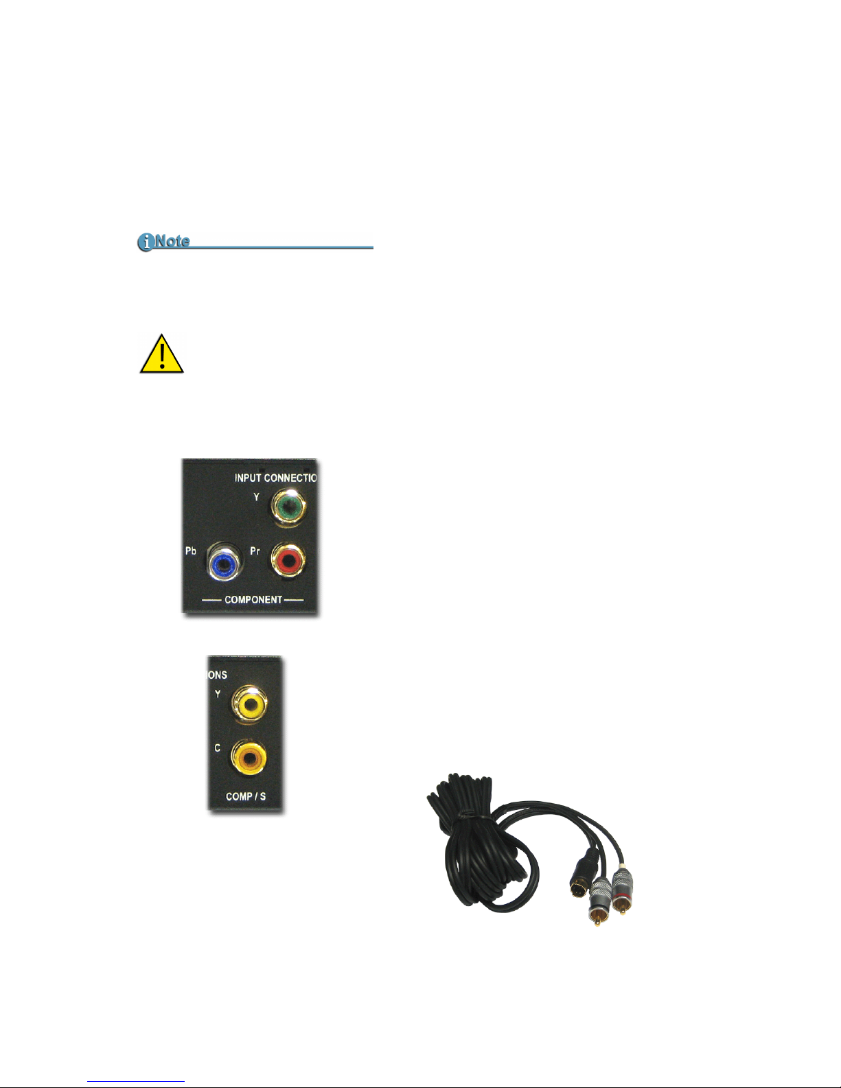
2. Connect cable(s) between the
camera’s video out and the
MCSDI-1’s input connectors.
Component Video Input
3 RCA jacks: Y, Pb and Pr.
Composite, Y/C (S-Video)
2 RCA jacks: Y (composite) and
C.
For S-video connections use a
Y/C breakout cable to make the
is connection.
Y/C Breakout Cable
(not included)
Page 31
Setup with Camera
MCSDI-1 Portable SD/HD-SDI Media Converter
17
Using the Cable Tie Kits
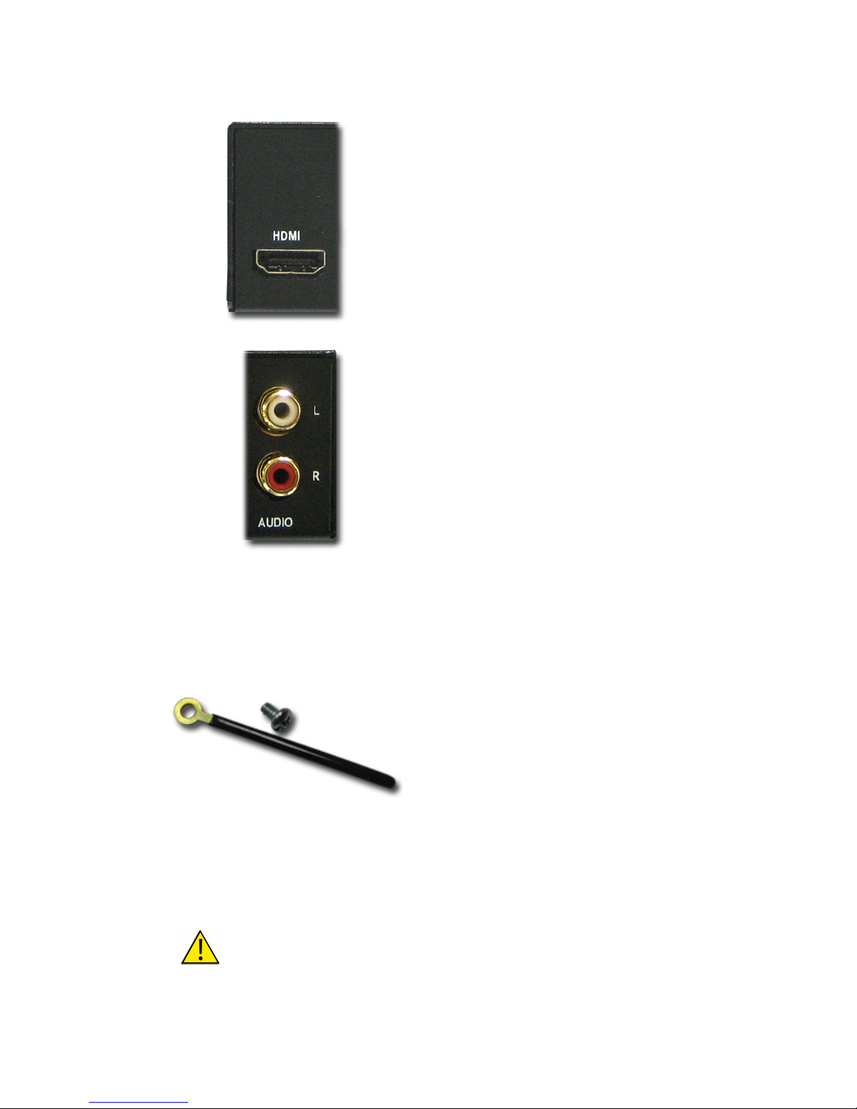
HDMI
Type A, 19-pin, HDMI.
3. If using camera analog audio
output, connect the camera to
the MCSDI-1’s Audio input
connectors.
1. Determine the best method to
route cables from the camera.
2. Secure the cable ties to the
bottom of the of the MCSDI-1,
on the side the cables will be
routed. For location of
mounting holes, see
Tripod
Mount (Bottom)
on page 9.
3. Group cables and bind then
together using the stiff metal
ties.
Use Screws Provided in Cable Tie Kits
Use the provided screws or screws of equal length to attach the Cable
Ties. Using longer screws can damage the MCSDI-1’s internal circuitry.
Page 32
Setup with Camera
MCSDI-1 Portable SD/HD-SDI Media Converter
18
Connecting MCSDI-1 to Studio and Power
The studio cable may be connected to a video switching device such
as the HX-1 Portable Video Switcher.
Test Signal
Test patterns are output when the MCSDI-1 has no valid input. The
output resolution is the same as the last valid input. The last
resolution is retained across power cycles.
For example, if a 720/60p component input is connected to the
MCSDI-1, when it is disconnected a 720/60p test pattern is displayed.
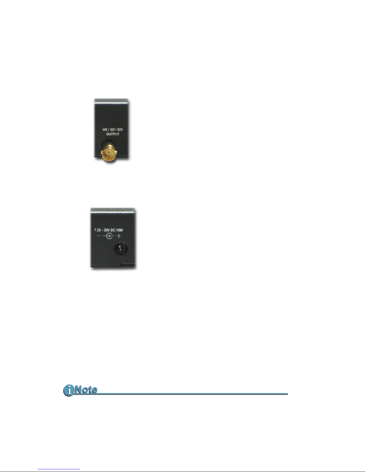
1. Connect the studio network
cable to the MCSDI-1’s SDI
output connector, BNC, 75 Ω,
on the front of the MCSD-1.
2. Connect power to the camera.
3. Connect the AC adapter’s DC
output to the MCSDI-1’s DC
input.
A valid input must be present for 5-10 seconds for the test pattern
resolution to change.
Page 33

MCSDI-1 Portable SD/HD-SDI Media Converter
19
Operating Conditions and Warranty
Operating Conditions
Temperature
• Operating: 0-40º C (32 - 104º F)
• Operating humidity: 30% to 90% RH
• Storage temperatures: -20 to 60° C (-4° to 140°F)
• Storage humidity: 85% RH or less
Warranty
Two years.
Page 34

MCSDI-1 Portable SD/HD-SDI Media Converter
20
Page 35

Page 36

MANL-1101-04
 Loading...