

Page 1
Models:
MC-735/735DMF/735DMT
MC-760/760DMF/760DMT
Detection Range 12m (MC-735)
15m (MC-760)
Input Voltage 9-16VDC
Current Drain about 15mA/12VDC
PIR section:
Optical lens data
PIR area: 22+12+6+4(MC-735)
44+12+6+4(MC-760)
Max coverage:12m*12m(MC-735)
15m*15m(MC-760)
Trigger indication: indicator twinkling
for about 10 sec.
Alarm and tamper
Alarm output: solid state relay,
NO 50mA/30V
The circuit will be open when alarm.
Alarm indication: LED on.
Event counter:optional,1-2 moving event.
Tamper interface: NO,50mA/30VDC
2.Specifications
Mounting
Surface or corner,at the height of 1.8 to 2.4 m
Note: Base allows single-sided corner mount at 45 to wall
Accessories:
BR-1:Surface mounted swivel bracket, adjustable 30
down and 45 left or right.
BR-2:BR-1 with a corner adapter
BR-3:BR-1 with a ceiling adapter
Environment:
Operating Temperature:-10 Cto50 C(14 Fto122 F)
Storage Temperature:-20 Cto60 C(-4 Fto40 F)
Anti whitelight: 9000 LUX
Physical
Size(H*W*D):112*59*41 m m
This device is coherent to Europe parliament direct 1999/5/EC
necessary items and rules, and also coherent to the main spirits
of radio and telecom terminal equipments on March 9 . 1999.
The device also reaches the Canadianstandard RSS-210. It can
be used indoor and outdoor, which canreach itsmaximum protection and avoidance of above interference.
th
3.Installation
3.1 General Guidelines
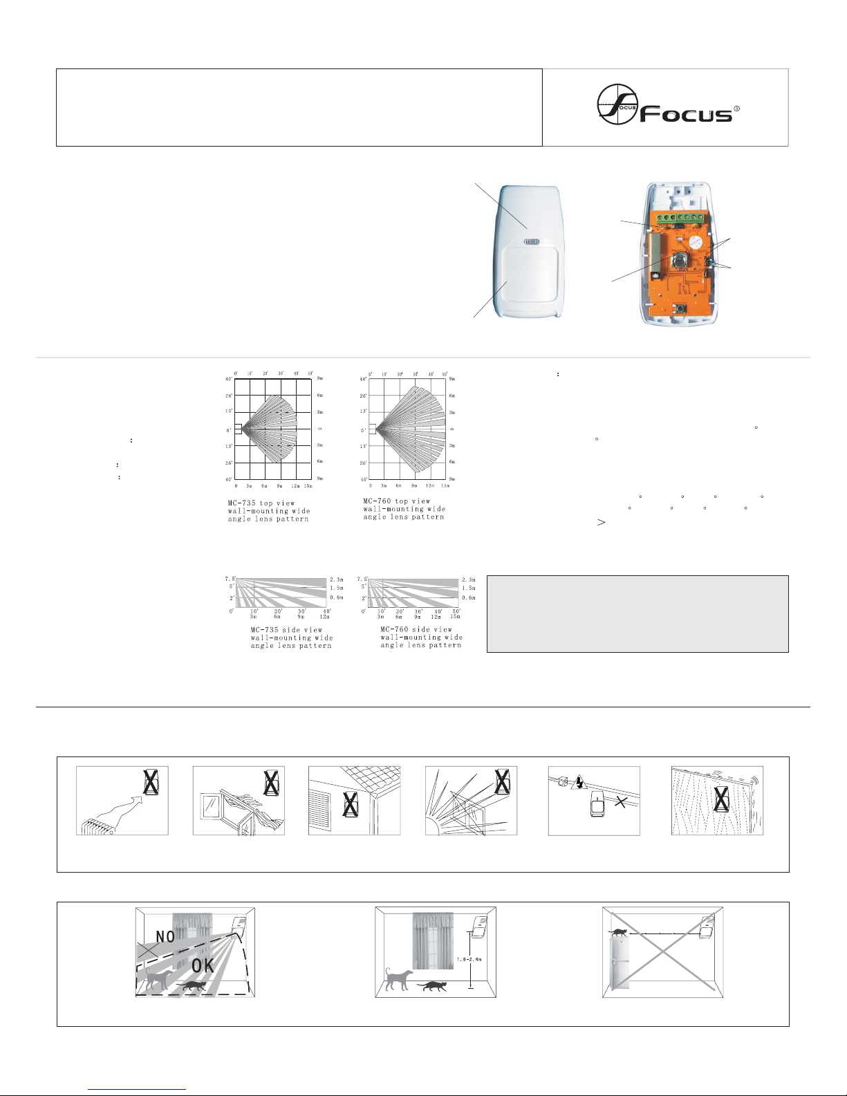
Don't facecold or heat
source directly
Do notopen window
of the saved area.
Do notmount it
outdoor.
Don't facethe
sun shinedirectly
Wire connection or
detector can'tbe near
to high-pressurecable
Don't installon a
unstable base.
The installation height of the detector
is 1.8-2.4 meters can Anti-pests
3.2Anti-pests installation
Never face the detector to the place that
pests can climb up directly
The upper part of the detection
area is non anti-pests area
1.Introduction
MC-735 is a digital micro-processing dual-tech detector adopting the technology
of DMF(digital memory focus ).DMT (dynamic matrixing time) .that can be
applying to decorative indoor with small size and flown line figure .The PIR parts
adopt column fresnel lens to effect of energy-receiving and four-layer screening
technology to anti blind-corner. Its advanced true motion recognition function .
anti-pets function can prevent wrong alarm to 15 kg pets or 5 cats .insects .mouse
or birds etc. It won’t trigger wrong alarm or miss alarm so it is far excellent in
function than common detectors. It can be used for different kind of indoor. With
the built-in large capability battery and exclusive circuitsave up powerl.
MC-735/760 intelligent with PIR
intrusion detector installation manual
WA LK TEST
LED
LENS
PIR
SENSOR
LED
switch
SINGLE OR
DOUBLE
SELECTION
JUMPER
LED
Figure 1.General View
Figure 2.Inside View
Page 2
Suggestion angle
installation
B. Insertthe wireline to
base throughbacl slot
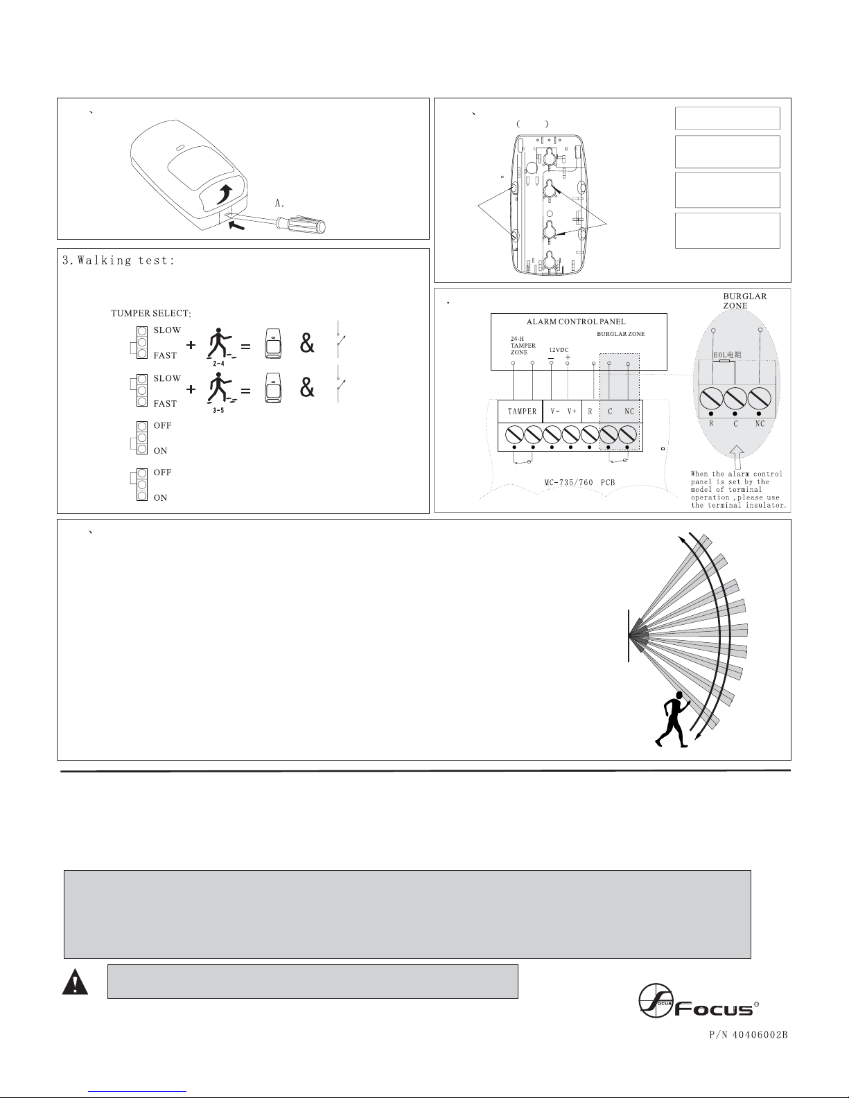
The detector will be in a visible area spy mode automatically after 3 minutes
of power connect. And adjust JUMPER to choosethe PIR function testing soley
or simultaneously.
Step-check LEDlighting
Normal workingstate (LED on)
3.3Illustrated Installation Procedure
3.3.1 Disassemble unit
3.3.2 Mount base
1.8-2.4m 6-8ft above ground
Singleside45
angled side
Surface
mount
(1 of 2)
A. Markthe drilling points
and drillingthe wall
C. Inserttwo dowels and
attach thebase to thewall
with twoscrews
D.Insert thebottom edge of
the largePCB under this
TAB& Press thetop edge in
3.10 Perform motion test to the detection area: install the cover and close the fasten part
(refer to the right diagram)
1. Start the test at least 2 minutes after power supply
2. Crossing to any direction of the detection area, your walking with 0.75m/s will cause the LED
indicator to light for 2-3 seconds (refer to the right diagram)
3 .Perform motion test from contrary directions in order to confirm the boundary of two sides. Make
confirmed that detection center pointing to the center of protected area.
4. Away from the detector 3 to 6 m, raise slowly your arm and reach into the detection zone, mark the
lower limit of PIR detection. Do the same step to confirm the upper limit.
5.the center of detection zone should not uphill incline. To obtaina gooddetection range, pleaseadjust
the vertical detection range, en-sure the detector is in a correct position.
6. After MW sensitivity or detection angle are adjusted, walking test
must be performed according to the above steps.
Even the most sophisticated detcetors can sometimes be defeated or may fail to warn due to :DC power failure/improper connection, malicious masking of the lens,tampering with the optical system, decreased sensitivity in ambient temperatures near that of the human body and unexpected failure of a component part.The above list includes the most common reasons for failure recommendedthat the detectorand the entire alarm system be checked weekly, to ensure proper performance.An alarm systemshould not be regarded as a substitute for insurance. Home & property owners or renters shouldbe prudent enough to continue insuringtheir lives& property,even thoughthey are protected by an alarm system.
WARNING! Changes or modifications to this unit not expressly approved by the party
responsible for compliance could void the user s authority to operate the equipment.
This devicehas beentested and found to comply with the limits for a Class B digitaldevice, pursuant harmful interference in residential installations .Thisequipment
generates,uses andcan radiate radio frequency energy and ,if not installed and used inaccordance with the ins-tructions ,may cause harmfulin-terference toradio and television reception.However, there is noguarantee that interference will not occur in aparti cular installation .If this device does cause such interference , which can be verfied by turning the device off and on,the user is encouraged to eliminate theinterference by one or more of the followingmeasures:
- Increasethe distance betweenthe device andthe receiver.
- Connectthe device toan outlet ona circuit different from the one that supplies power to the receiver.
- Consultthe dealer oran expericnced radio/TVtechnician.
4.Special comments
Loose the screw
6 Wire up the terminal block
 Loading...