

Page 1

iTView DV
User’s Guide
Rev. 9/01
Page 2

FCC NOTICE
This equipment has been tested and found to comply with the limits
for a Class B digital device, pursuant to Part 15 of the FCC Rules.
These limits are designed to provide reasonable protection against
harmful interference in a residential installation. This equipment
generates, uses and can radiate radio frequency energy, and if not
installed and used in accordance with the installation manual, may
cause harmful interference to radio communications. However, there
is no guarantee that interference will not occur in a particular
installation. If this equipment does cause harmful interference to
radio or television reception, which can be determined by turning the
equipment on and off, the user is encouraged to try to correct the
interference by one or more of the following measures:
• This unit was tested with shielded cable. Therefore, for
continued compliance, use the shielded cables provided with the
unit.
• Re-orient or relocate the unit or receiving antenna.
• Increase the separation between the computer/converter and
television.
• Connect the equipment to an outlet on a circuit different from
that to which the receiver is connected.
• Consult the dealer or an experienced radio/TV technician for
help.
You may find the following booklet helpful:
How to Identify and Resolve Radio-TV Interference Problems (stock
number 004-000-000345-4)
To order the booklet, write to:
The U.S. Government Printing Office
Washington D.C. 20402
Page 3

COPYRIGHT
This document and the software described in it are copyrighted under
United States Copyright Laws. No part of this document or software
may be copied without prior written consent from FOCUS
Enhancements, Inc. except in the normal use of the software as
described in this documentation. All printed circuits, their physical
implementation on printed circuit boards and associated software are
copyrighted with all rights reserved. Under the copyright laws, the
printed circuit board, or the software programs provided may not be
copied in whole or part, without written consent of FOCUS
Enhancements, Inc., except in the normal use of the software
programs to make a backup copy. This exception does not allow
copies to be made for others, whether sold or not, but all of the
material may be sold, given, or loaned to another person. Under the
law, copying includes translating into another language or format.
Mac OS 7.1, 8.5, 9.0 and 10 are trademarks of the
Apple Corporation. All other products named are trademarks of
their respective manufacturers.
©2001 FOCUS Enhancements, Inc. All Rights Reserved
Page 4

This is a blank page
Table of Contents
CHAPTER 1 INTRODUCTION 4
CHAPTER 2 HARDWARE INSTALLATION 9
Packing List 9
Inspecting the Equipment 10
Installing the RGB Cover on your iMac DV 10
Connecting the iTView DV to a Television 13
Connecting the iTView DV to a VCR 18
Functions of the iTView DV LED 20
CHAPTER 3 iTVIEW DV SOFTWARE 21
Installing the iTView DV Control Panel Software 21
Screen Controls 22
TV Output Controls 24
Picture Setup 26
Additional Features 28
CHAPTER 4 TUNING YOUR TELEVISION 31
Brightness 32
Color 32
Sharpness 32
Tint or Hue 32
CHAPTER 5 TROUBLESHOOTING 33
Returning a Damaged or Failed iTView DV Unit 35
Page 5

iTView DV User’s Guide
Preface 1
About the User’s Guide
The iTView DV User’s Guide is designed to help you to quickly and
easily connect the hardware and install the software for this product.
The guide is divided into the following chapters:
Chapter 1: Introduction: which describes the key features and
functionality of the product and some of its many uses. The chapter
also discusses the notation conventions used in the guide.
Chapter 2: Hardware Installation: which describes the information
you should know before installing and connecting the iTView DV
hardware, and the steps required to perform the installation.
Chapter 3: iTView DV Software: Describes the steps required to
install the iTView DV software control panel and how to operate the
program.
Chapter 4: Tuning Your Television : this chapter describes the
methods you can use to tune the image on your television
Chapter 5: Troubleshooting : describes possible problems that you
might encounter and ways to solve them..
Page 6
iTView DV User’s Guide
About This Guide 2
Notation Conventions
This user’s guide uses the following conventions to specify certain
types of information.
Warns you about potential problems and hazards during
the installation or use of the product. Read these
warnings carefully, and be sure you understand how
they relate to the installation procedures before
proceeding.
Note: Points out important or useful information.
Contact Information
To get information on the reseller nearest to you, to order
replacement parts, or for technical support contact one of the
following:
Worldwide Headquarters
1370 Dell Avenue
Campbell, CA 95008
Customer Service 800-338-3348 (U.S. Only)
Technical Support 408-370-9963
Page 7

Page 8

iTView DV User’s Guide
Chapter 1 4
Chapter 1 Introduction
The iTView DV converts the VGA output from your computer into
video that can be displayed on a television or recorded to a VCR.
iTView DV automatically detects VGA ,SVGA, and XGA output
frequencies up to 152Hz and synchronizes it with your television. The
result is a high quality, flicker-free television display from your
computer.
Features
The iTView DV includes the following features:
• Screen position controls
• Variable horizontal and vertical scaling controls
• Variable zoom controls
• Image freeze control
• Brightness,Contrast, Sharpness, Flicker Filter, Color Saturation
• 2D flicker filter controls
• Easy plug-and-play installation for iMac DV personal computers
• Compatibility with any size television monitor (NTSC/PAL) with
an RCA (composite), S-Video, or SCART (Europe only) input
connector.
• Support for 640 x 480 (VGA), 800 x 600 (SVGA) and 1024 x 768
(XGA) resolution at frequencies up to 152Hz
• Support for 24-bit color
• TrueScale™ image compression that precisely fits the image on
your television without dropping lines or altering video resolution
• Electronic Marker™ Software
Page 9
iTView DV User’s Guide
Introduction 5
Modes of Operation
The iTView DV has ability to operate in two separate modes:
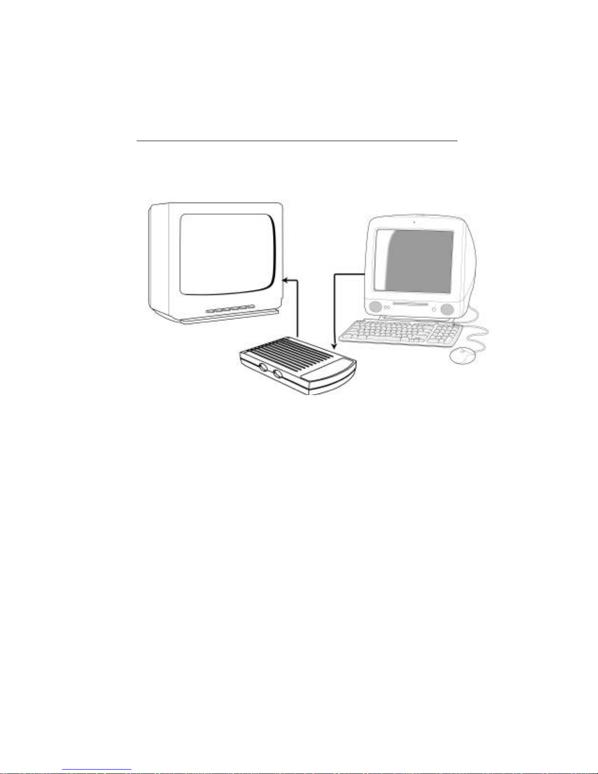
Figure 1-1: Presentation Mode
1. Presentation Mode: Display the same image on your computer
and your television.
Page 10
iTView DV User’s Guide
Chapter 1 6
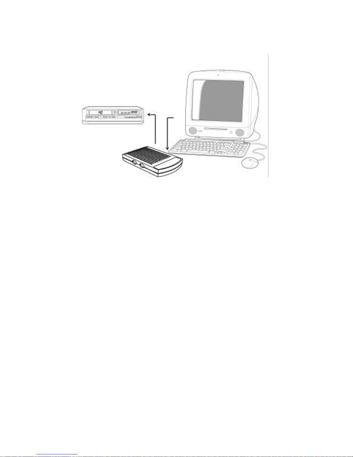
Figure 1-2: Video Record Mode
2. Video Record Mode: Record your video image or digital movie
directly to your videotape.
Page 11

iTView DV User’s Guide
Introduction 7
Suggested Uses for the iTView DV
The iTView DV can be used for the following:
• Bring sales or other multimedia presentations from a laptop to a
large TV
• Output your digital movies to television
• Demonstrate a new software package using a large screen TV
• Project computer games onto a TV screen
• Cruise the Internet on a television
• Conferencing via TV
• E-Mail
• Collaborating with others on computer-based projects
Page 12
iTView DV User’s Guide
Chapter 1 8
Specifications
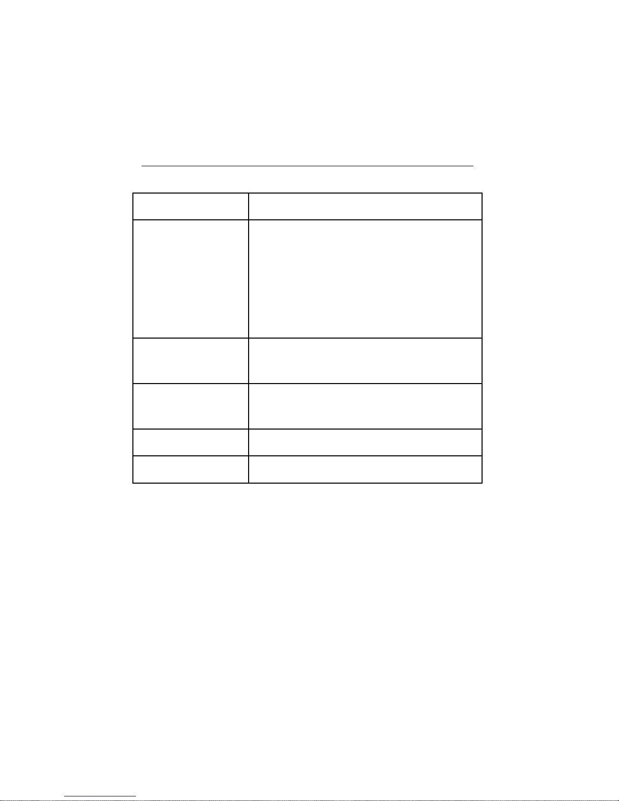
Table 1: iTView DV Specifications.
Computer Compatibility • Any iMac DV
Television Compatibility • Works with any size television monitor (NTSC/PAL)
with an RCA (composite), S-Video, or SCART
(Europe only) input connector. For television
receivers or televisions without composite or S-Video
inputs, an RF Modulator is required (Radio Shack
#15-1283)
Color Modes and
Resolution
• Supports up to 16,777,216 colors (24-bit), and up to
1024 x 768 at refresh rates up to 152Hz
Power Supply • Maximum consumption 5 volt regulated DC,
700 mA
Unit Weight • 184 grams (without cables)
Unit Dimensions • 12 cm x 7cm x 2.5cm
Page 13

iTView DV User’s Guide
Chapter 2 9
Chapter 2 Hardware
Installation
This chapter describes the information you should know before
installing and connecting the iTView DV hardware, and the steps
required to perform the installation.
System Requirements
Before installation, the following are system requirements for the
operation of the iTView DV:
iMac DV (Any Flavor)
• iMac personal computer
• Television with S-Video or Composite Video output.
Checking the Packing List
Check the packing list that is included in this manual. Compare the
list with the equipment you have purchased. Be sure that you have
received everything that is on the list. If anything is missing, contact
FOCUS Enhancements Customer Service department by calling
1-800-338-3348.
Packing List
Your iTView DV includes the following items:
Page 14
iTView DV User’s Guide
Hardware Installation 10
• iTView DV
• Power adapter 5V @700mA
• S-Video and Composite video cables (US only)
• SCART Cable (Europe only)
• Electronic Marker™ software
• User’s guide and Quick-Start guide ( On CD ROM)
• iTView DV Control Panel Software
Inspecting the Equipment
Before installing and connecting the hardware, inspect it for any
damage, which may have been incurred during shipment. Perform a
thorough inspection, looking for dents, scratches, or loose parts.
Look for anything that appears unusual or out-of-the ordinary. If any
of the equipment is damaged, contact FOCUS Enhancement’s
Customer Service department by calling 1-800-333-3348.
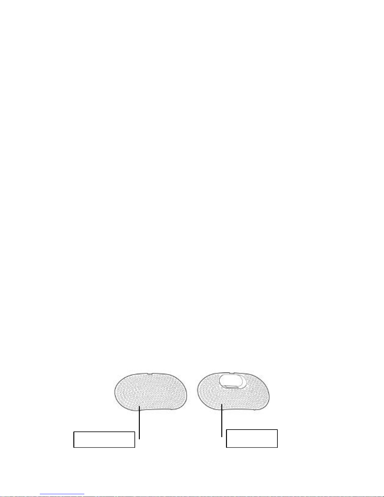
Installing the RGB Cover on your iMac DV
To obtain access to the RGB port on your iMac DV you will need to
install the RGB Cover on the rear of the computer. The following
outlines the procedure for removing the standard cover and installing
the RGB cover.
.
Standard Cover
RGB Cover
Page 15
iTView DV User’s Guide
Chapter 2 11
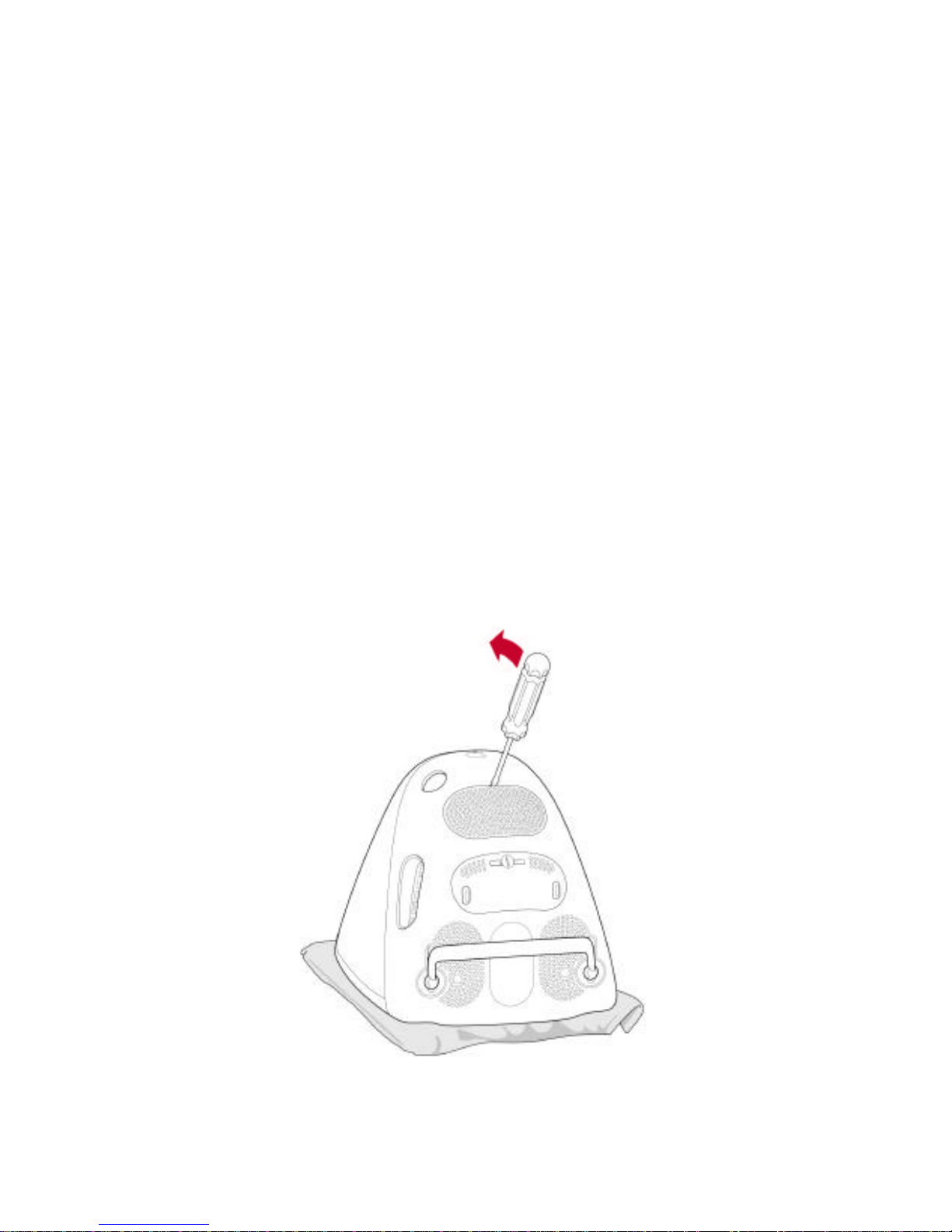
Perform the following steps to install the RGB Cover on your
iMac DV:
1. Turn off your iMac and unplug the power cord from the wall. If
your internal modem is connected to a telephone line,
disconnect the telephone line from the modem.
2. Place a soft cloth or towel large enough to cover the front of the
iMac on a desk, table, or other flat surface.
3. Carefully, place the computer, screen down, on the cloth.
Page 16
iTView DV User’s Guide
Hardware Installation 12
4. Using a flat screwdriver, remove the panel covering the VGA
connector. Refer to the image above.
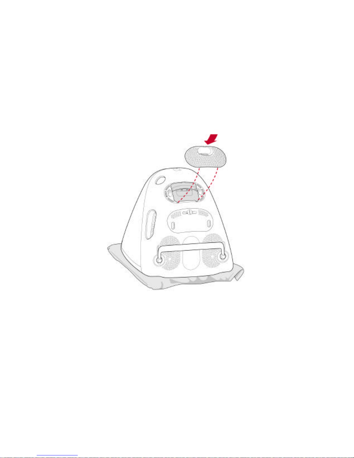
5. Insert the RGB Cover into the slots on the rear of the iMac.
Page 17

iTView DV User’s Guide
Chapter 2 13
Connecting the iTView DV to a Television
After installing the RGB cover and connecting the RGB cable to the
iMac DV, you will need to connect the iTView DV to a television or
VCR. This section describes the connections available and how to
use them. (If you are planning to connect to a VCR, see "Connecting
to a VCR" below.) There are three possible ways to connect to a
television:
• Using a composite video connection
• Using an S-Video connection
• Using a SCART cable (Europe only)
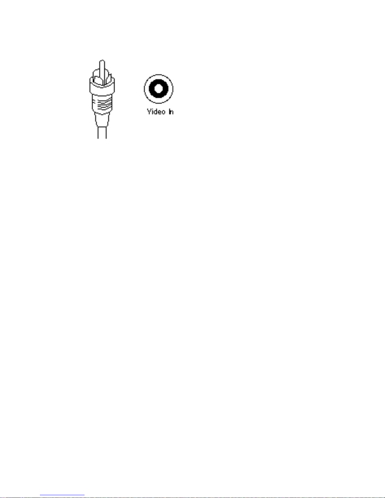
Composite Video Connection
Composite video is a connection type used by most televisions,
VCRs, laserdisc players, and certain LCD panels. The connectors on
a composite video cable have an RCA-type plug. The plug has a long
metal pin projecting from its center and plugs into the composite
video in port at the rear of the television.
Page 18
iTView DV User’s Guide
Hardware Installation 14
Figure 2-3: Composite Video Connectors
To determine if your television supports composite video, look for a
port on your television that matches the composite video out port at
the side of the iTView DV unit.
Note: The composite video port on the television may or may
not be labeled "video in.” The Video input jack will have
a yellow center.
S-Video Connection
S-Video is a high-quality video connection used by some televisions,
video cameras and VCRs. The connector on an S-Video cable has a
round plug with several small metal pins. It plugs into the S-Video
output port at the side of the iTView DV unit.
Note: The S-Video connection is a newer video standard. This
type connection improves color, clarity, and resolution.
The S-Video connection is the reccomended connection
to use, if present..
Page 19

iTView DV User’s Guide
Chapter 2 15
Figure 2-4: S-Video Connectors
To determine if your television or supports S-Video, look for a port at
the rear of the television that matches the S-Video output port at the
side of the iTView DV Unit.
Note: The S-Video port on the television may or may not be
labeled "S-Video in."
SCART Connection (Europe Only)
SCART is a high-quality video connection used on most televisions
and VCR's in Europe. The connector on the SCART cable provided
with the iTView DV has two different connectors. The larger end of
the cable is rectangular in shape and contains 20 small metal pins.
This larger end of the cable plugs into the matching port on the
television or VCR. The smaller end of the SCART cable has a round
plug with several small metal pins and connects to the port labeled
SCART/S-Video on the iTView DV.
Additionally, the SCART connector provided with the iTView
DV can accept audio input from your computer. To utilize this
function, connect a standard 1/8" male mini stereo cable (not
included) to the female connector attached to the larger end of the
SCART cable.
Page 20
iTView DV User’s Guide
Hardware Installation 16
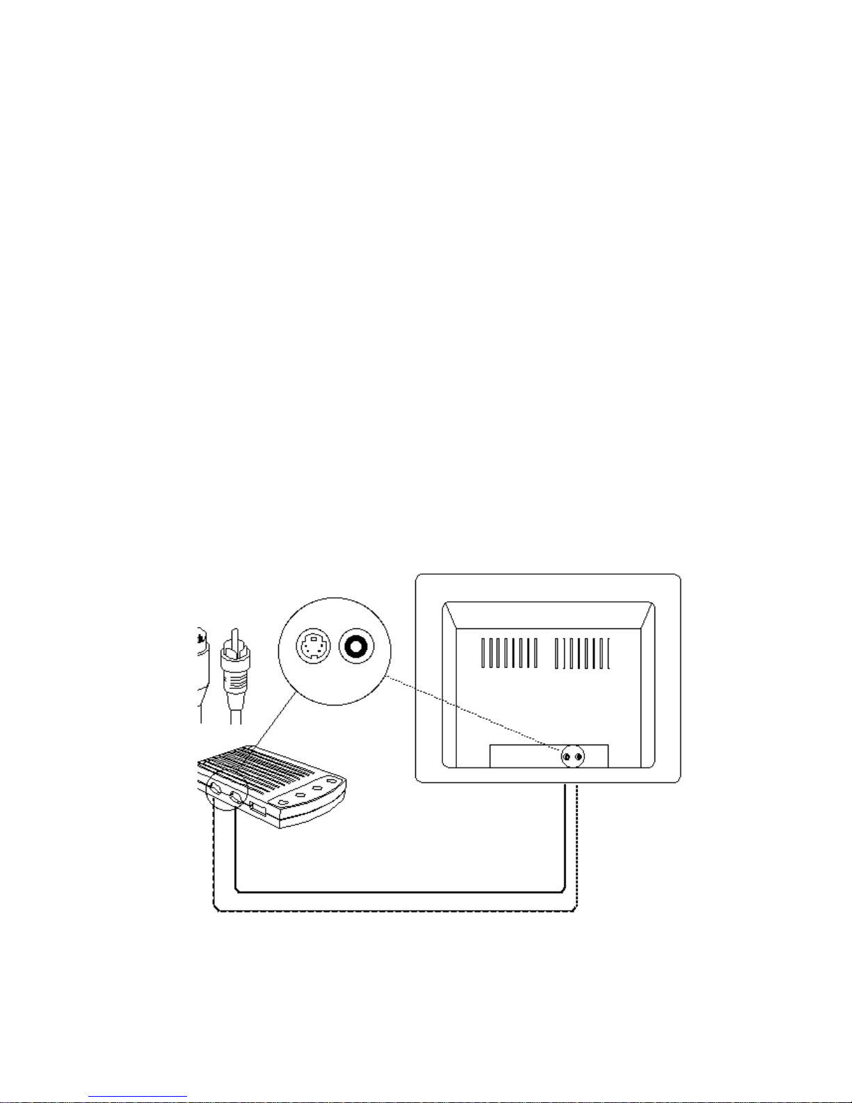
To connect the iTView DV unit to your television, perform the
following steps:
1. Connect one end of the supplied composite video cable to the
“Comp Video” port located on the side of the iTView DV unit, or
connect the male end of the S-Video cable to the port on the
side of the iTView DV labeled either "SCART/S-Video."
2. Connect the other end of the composite cable or S-Video cable
to the Comp Video in or S-Video in port at on the television.
3. Turn the television on.
4. Plug in the power adapter for the iTView DV.
5. Turn your computer on. If the cables have been connected
correctly, the image from the computer monitor should now
appear on the television screen.
Figure 2-5: Connecting iTView DV to the Television
Page 21

iTView DV User’s Guide
Chapter 2 17
When you are looking at the television to make these connections,
you may see an input labeled ANT IN. This input is used by cable TV
companies and uses a different type of video than that used by
iTView DV. It is not possible to connect directly to this input. If this is
the only input available, and you do not have a VCR, this input can
be used with an RF modulator. See below for further information.
Note: Because the port may not be labeled, you will need to
match the port to the connector you are using.
Page 22

iTView DV User’s Guide
Hardware Installation 18
Connecting the iTView DV to a VCR
In certain configurations, the video will be run through a VCR.
Therefore the unit must be connected to the VCR. By connecting the
iTView DV unit, you will also be able to record the computer screen
to videotape.
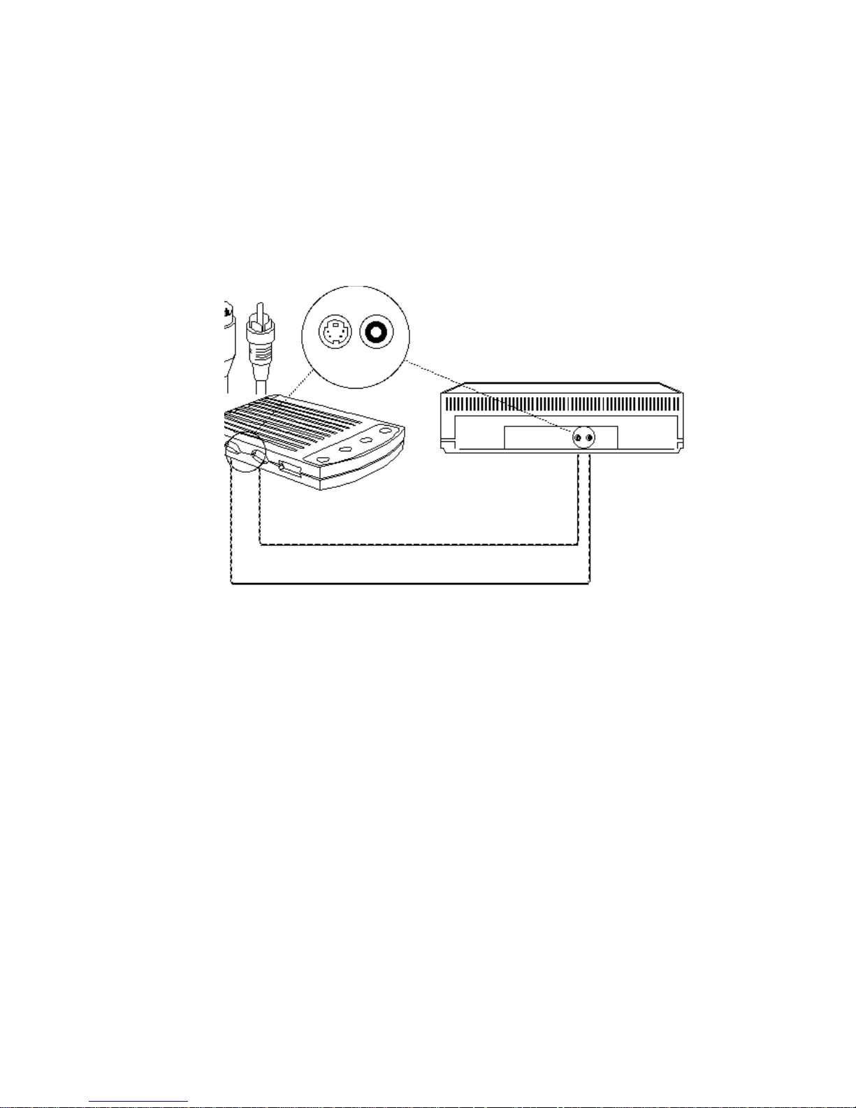
To connect your iTView DV to a VCR, perform the following
steps:
1. Connect one end of the supplied composite video cable to the
“Comp Video” port located on the side of the iTView DV unit, or
connect the male end of the S-Video cable to the port on the
side of the iTView DV labeled "SCART/S-Video.”
2. Connect the other end of the composite cable or S-Video cable
to the port at the rear of your VCR labeled "Video Input" or
“AUX-IN,” “AV-IN,” or “S-VIDEO IN.”
3. Turn on the VCR.
4. Turn on your television and tune it to channel 3 or 4.
5. Plug in the power supply for the iTView DV.
6. Turn the computer on.
7. Find a button on the front of the VCR called "Line," "TV/Video,"
"Video Input," or something similar. Press the button. If the
cables have been connected correctly, the image from the
computer monitor should now appear on the television screen.
Page 23
iTView DV User’s Guide
Chapter 2 19
Note If your VCR does not have a button specifying video-in,
use your VCR’s remote control to find an on-screen
programming system. Using the programming system to
set the VCR to receive external video. If you are unsure
about how to do this, refer to the VCR owner’s manual.
Figure 2-6: Connecting the iTView DV to a VCR
Page 24

iTView DV User’s Guide
Hardware Installation 20
Functions of the iTView DV LED
The LED located on the front of the iTView DV indicates a connection
has been established between the iMac DV and the iTView DV. The
LED will glow green if there is a good connection.
Page 25

iTView DV User’s Guide
Chapter 3 21
Chapter 3 iTView DV
Software
This chapter describes how to install the iTView DV Control Panel
Software which is shipped with the iTView DV. The chapter also
describes how to use the software to manipulate the computer image
on the television screen.
Installing the iTView DV Control Panel
Software
Perform the following steps to install the iTView DV control panel on
your Macintosh
1. Insert the iTView DV CD-ROM into the CD-ROM drive.
2. Open the iTView CD ROM when it appears on the desktop
3. When the CD-ROM icon appears on your desktop click on it.
4. When the CD-ROM folder opens on your desktop click on the
installer file. This will install the iTView DV control panel
software on your computer’s hard drive.
Re-Boot your MAC. You may now access the iTView DV Control
Panel via the Control Panels option under the Apple Menu.
Page 26
iTView DV User’s Guide
Image Control 22
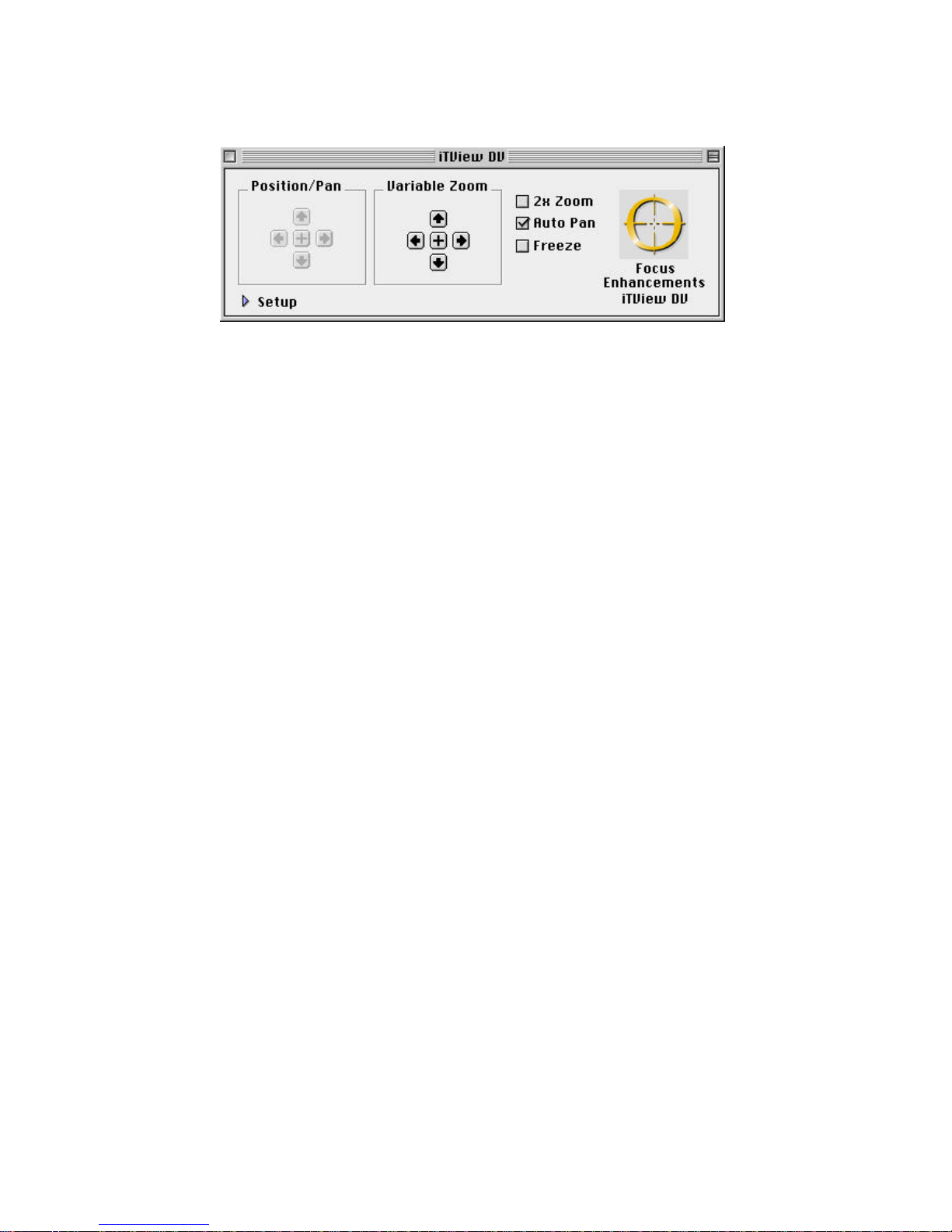
Figure 3-1 iTView DV Control Panel
Screen Controls
From the main control panel you will be able to adjust the following
aspects of the computer image on the TV.
• Screen Position
• Image Zoom
• Image Freeze
• Control Strip Feature
Screen Position
After powering on your iTView DV you might notice that the computer
image is not centered on the television screen. Using the four
directional arrow keys on the control panel you can position the
computer image to fit precisely on your television.
Image Zoom
The iTView DV control panel software also gives you the ability to
zoom into any area on the television screen. You have two options
for zooming into an image.
Page 27
iTView DV User’s Guide
Chapter 3 23
• 2X Zoom: By clicking on the 2X Zoom button you can zoom the
entire screen by 2X. Once in Zoom mode use the mouse to pan
in any direction on the screen.
• Variable Zoom: You can also zoom the image on the TV screen
by using the four-directional arrow keys on the control panel.
The variable zoom feature allows you to control the zoom factor
for both horizontally and vertically. By clicking on the directional
arrow keys you can zoom the image.
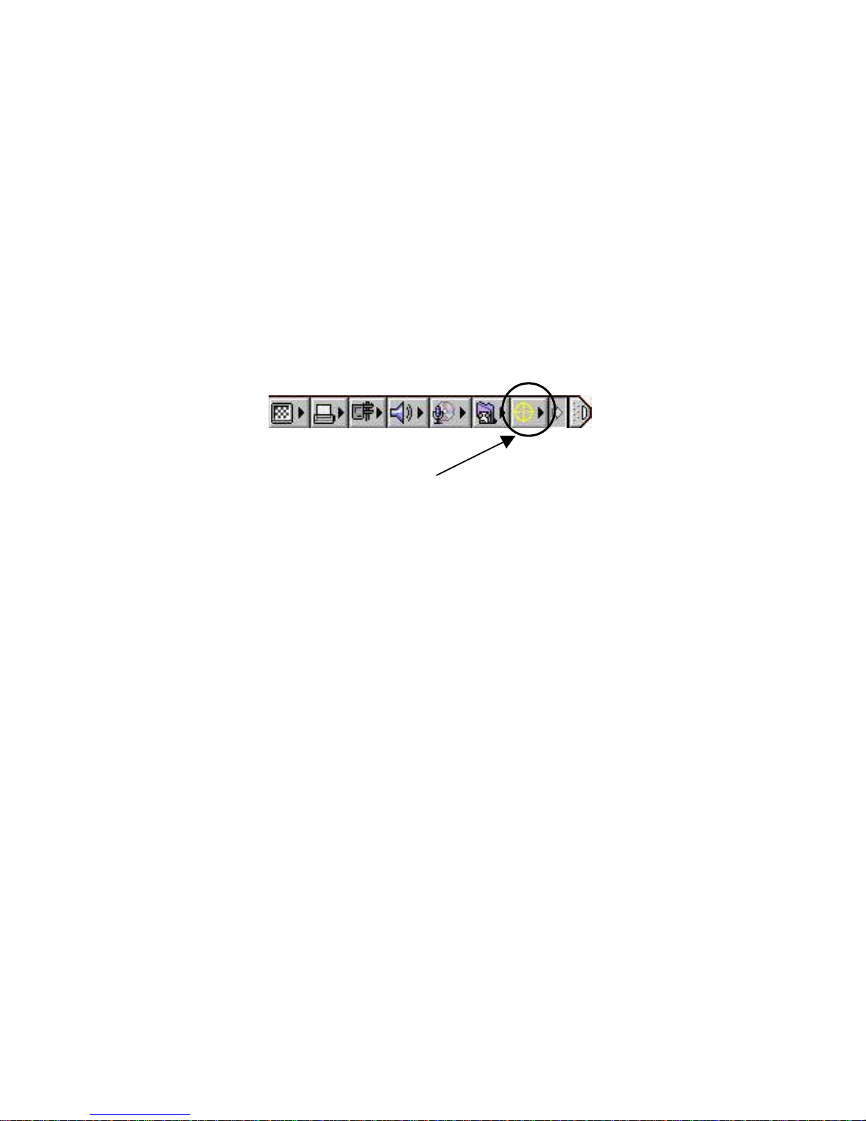
iTView DV Control Strip
• Control Strip Feature: By clicking on the control strip on your
desktop you can obtain access to the iTView DV’s control strip
feature. This feature allows you to easily control 2x Zoom, Auto
Pan, and freeze.
Click on the control strip with the FOCUS Crosshairs to obtain
access to these featrues.
Image Freeze
By clicking on the image freeze check box on the control panel you
can freeze the current screen on the television. While the image is
frozen on the screen changes to the computer image will not be
visible on the television. To advance the screen image, turn off the
freeze control.
Page 28
iTView DV User’s Guide
Image Control 24
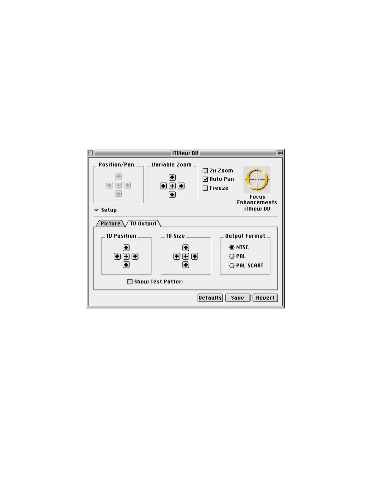
Access to Setup Controls
There are two additional menus available to you within the iTView DV
control panel, these are Picture Setup and TV Setup. To access
these controls click on the arrow icon to the left of the word setup in
the lower, left hand corner of the control panel. (refer to figure 3-1
above)
Figure 3-2 iTView DV TV Setup
TV Output Controls
The TV Output screen controls the following:
• TV Position
• TV Size
• Output Format
Page 29

iTView DV User’s Guide
Chapter 3 25
• Test Pattern Generator
Output Format
Your iTView DV can output video in three formats. These are:
NTSC, PAL, and PAL SCART. If you are located in North America,
Central America, Japan, Taiwan, or Korea you will use the NTSC
setting. If you are located in The UK or Europe you will need to set
the control panel to PAL. If you are using a television equipped with
a SCART input you will need to set the control panel to PAL SCART.
(see Figure 3-2 above)
TV Position/TV Size/Test Pattern Generator
The iTView DV fits your computer image on the television screen by
setting that image into a user-defined window. You have the ablility
to set the size and position of this window. This control should only
need to be set once. The parameters you set will be saved for the
next time you use the iTView DV.
Note: The setting you choose may need to be adjusted if you
connect a different television to the system.
The fastest way to set these controls is to click on the “Show Test
Pattern” button first. (see figure 3-2 above) After clicking on the test
pattern button the iTView DV will project a test pattern on your
television. This test pattern will enable you to easily adjust screen
positioning, screen sizing, and all color adjustments.
Once the test pattern is on the television, use the arrow buttons on
the control panel to size and position the computer image on the
Page 30

iTView DV User’s Guide
Image Control 26
television screen.
Saving your Settings
Once you have set the TV Output Format and adjusted the sizing
and positioning of the computer image you can save your settings by
clicking on the “Save” Button on the control panel. After clicking on
this button, your preferences will be saved until you choose to
change them and click on the save button again.
If you are unhappy with your settings and would like to go back to
your last saved set of preferences simply click on the “Revert” key on
the control panel. This will set all user-definable preferences back to
your last saved setting. If you would like to set all controls to the
factory default click on the button marked “Defaults”.
Picture Setup
After setting your user preferences for the TV Setup you will want to
adjust the quality of the image on the television screen. You will
need to click on the folder tab labeled “Picture” to access the picture
adjustments.
Page 31
iTView DV User’s Guide
Chapter 3 27
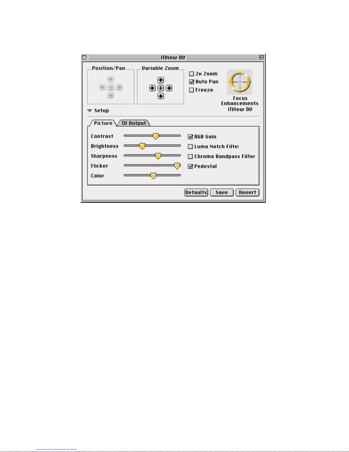
Figure 3-3 iTView DV Picture Adjustments
After clicking on the Picture tab you will see the controls which will
allow you to adjust the following aspects of the computer image on
the TV:
• Contrast
• Brightness
• Sharpness
• Flicker Filter
• Color (Color Level)
Contrast/Brightness/Sharpness
Adjusting the Contrast, Brightness, and Sharpness of the computer
image on the television is very simple. The slider bars on the control
panel can be “grabbed” by hovering over the desired control with the
Page 32

iTView DV User’s Guide
Image Control 28
cursor and holding down the mouse button. After grabbing the slider
control with the mouse you can increase Contrast, Brightness, or
Sharpness by dragging the slider to the right. To decrease Contrast,
Brightness, or Sharpness drag the appropriate slider to the left. See
Figure 3-3 above.
Additional Features
There are four additional controls you can manipulate within this
section of the iTView DV Control Panel. These are:
• RGB Gain
• Luma Notch Filter
• Chroma Bandpass Filter
• Pedistal
These controls are intended for specific situations, these situations
are outlined below.
RGB Gain
By clicking on the RGB gain button you will optimize the output from
the iTView DV for SCART output. If you are in Europe and using the
PAL/SCART connection you will be able to improve the quality of the
image by clicking the RGB Gain button.
Page 33

iTView DV User’s Guide
Chapter 3 29
Luma Notch Filter
The Luma Notch Filter is intended to isolate a certain video
frequency present in all video signals that may cause distortion in the
image. By clicking the Luma Notch Filter on you will see an
improved picture on many TVs not equipped with this type of filter
already.
Chroma Bandpass Filter
The Chroma Bandpass filter is much like the Luma Notch Filter, in
that the filter is designed to isolate a specific video frequency.
However, the Chroma Bandpass filter works only when you are
outputting to composite video. If you are using a composite video
connection, you will see an improvement in the computer image on
the TV.
Pedistal
If you are in the United States, you should turn pedistal on. Your
North American television set is designed to operate this way.
If you are in Japan, you will need to turn this feature off.
Saving your Settings
Once you have set the TV Output Format and adjusted the sizing
and positioning of the computer image you can save your settings by
clicking on the “Save” Button on the control panel. After clicking on
this button, your preferences will be saved until you choose to
change them and click on the save button again.
If you are unhappy with your settings and would like to go back to
your last saved set of preferences simply click on the “Revert” key on
Page 34

iTView DV User’s Guide
Image Control 30
the control panel. This will set all user-definable preferences back to
your last saved setting. If you would like to set all controls to the
factory default click on the button marked “Defaults”.
Page 35

iTView DV User’s Guide
Chapter 4 31
Chapter 4 Tuning Your
Television
This chapter describes the methods you can use to tune the image
on your television.
Using Your Television’s Video Settings
Picture quality varies from television to television. To obtain the
clearest and sharpest picture from your television, it is important to
spend some time adjusting the television’s video settings. The
following are some suggestions for tuning the video output you see
on the screen.
Note: The items listed below are general tips for all televisions.
Most televisions have one or more of the controls listed.
However, the results of adjusting these items depend on
your specific television.
Note: Depending on the model of the television, the image is
adjusted using buttons or on-screen programming.
Check your owner’s manual to determine how the image
is adjusted on your television.
Page 36

iTView DV User’s Guide
Tuning Your Television 32
Brightness
The Brightness adjustment on the television adjusts the brightness
levels of black areas of the picture. Raise or lower the brightness
until the picture appears bright without a "blooming" effect. The sides
of the picture should be straight, not curved or bowed.
Color
The color adjustment on the television adjusts the intensity of the
colors in the picture. Adjust the color control until the picture is clear
and has a minimal amount of "color-bleeding." If the color is turned
up too high, the color will be over-saturated.
Sharpness
The Sharpness adjustment on your television adjusts the clarity of
the edges around objects for the clearest picture quality. The general
rule when adjusting sharpness is to turn it up anywhere from its
middle to highest level.
Tint or Hue
The Tint or Hue adjustment on your television adjusts the color of the
flesh tones to more green or red. The most effective way to use this
adjustment is to display row or column of colors side-by-side and
then adjust them until the color appears correct to you.
Page 37

iTView DV User’s Guide
Chapter 5 33
Chapter 5
Troubleshooting
This chapter describes possible problems that you might encounter
and ways to solve them.
Problem Possible Causes/Solutions
No video from the
iTView DV
• Check the connection from the computer’s video output
port to the VGA in port at the rear of the TView unit.
• Check the connection from the comp video out port or
S-Video out port to the input on your monitor or VCR.
• Ensure that the TV or VCR is ON.
• Check the connection from the power supply. Is the
TView unit plugged in? Is the LED ON and green?
• Ensure that your television or VCR has been
configured to accept auxiliary video input.
• Ensure that the iTView DV is connected to the
appropriate video connector on your TV or VCR. At the
TV or VCR end, the cable should be connected to the
VIDEO IN, or AUX IN port.
Flicker, or other
distortion on your
screen
• Use of an RF modulator may cause image quality
problems. If at all possible, avoid those devices that
convert the iTView DV signal into an antenna signal.
Page 38

iTView DV User’s Guide
Troubleshooting 34
Colors are poor
quality or nonexistent
• Adjust the color controls on the iTView DV control
panel.
• Adjust the brightness and contrast control of the iTView
DV in the Control Panel Software.
• Use of an RF modulator may cause image quality
problems. If at all possible, avoid those devices that
convert the iTView DV signal into an antenna signal.
TV image overshoots
or fails to fill the
screen
• Use the iTView DV’s horizontal and vertical controls to
adjust positioning.
• Adjust the iTView DV’s TV size control to the
appropriate setting.
.
Green LED does not
light
• Check power connections.
• Check software configuration (if the iTView DV is not
communicating with the software control panel, the
controls will be grayed out.
• Possible power supply or iTView DV failure.
iTView DV failure • Inspect the iTView DV unit for signs of damage (i.e.
broken pins, severed wires, etc.).
Page 39

iTView DV User’s Guide
Chapter 5 35
Returning a Damaged or Failed iTView DV
Unit
To return a iTView DV unit, follow these steps:
1. Contact FOCUS Enhancements Technical Support at 1-408370-9963. A representative is available from 8:00 AM to 5:00PM
Pacific Standard Time (PST). Explain the nature of the problem
and any evidence of damage you may have found. The
customer representative will either assist you with the specific
problem or give you a Return Materials Authorization Number.
Note: No goods will be accepted for warranty repair or return
without an RMA number.
2. Pack the iTView DV carefully. If possible, use the original
shipping package. Send the package pre-paid and insured via
United Parcel Service (UPS) or US Mail to:
FOCUS Enhancements
ATTN: RMA# (Your RMA Number)
1370 Dell Avenue
Campbell, CA 95008
FOCUS Enhancements will repair or replace your iTView DV within 5-15
working days. For units not covered under the 1 year warranty, or
where the warranty has been voided, we charge a minimum fee of $90.00.
 Loading...