

Page 1

600 Research Drive
Wilmington, MA 01887
Tech support
(978) 988-5505
www.focusinfo.com
HyperConverter 1024
HyperConverter 1280
User's Manual
HyperConverter User’s Manual 0006-5000-503
1
Page 2

2
HyperConverter User’s Manual 0006-5000-503
Page 3

Table of Contents
1.0 INTRODUCTION........................................................................................................................................ 4
1.1 THE HYPERCONVERTER FAMILY....................................................................................................................... 4
1.2 OPERATIONAL SPECIFICATIONS......................................................................................................................... 7
1.3 PRODUCT ORDERING OPTIONS........................................................................................................................ 11
2.0 INSTALLATION........................................................................................................................................14
2.1 IBM PC BOARD VERSION............................................................................................................................... 14
2.2 IBM PC DESKTOP VERSION............................................................................................................................ 16
2.3 MAC DESKTOP VERSION................................................................................................................................ 17
2.4 SUN DESKTOP VERSION.................................................................................................................................. 21
2.5 SGI DESKTOP VERSION .................................................................................................................................. 22
2.6 WORKSTATION DESKTOP VERSION.................................................................................................................. 23
2.7 HYPERCONVERTER-1280R RACKMOUNT INSTALLATION................................................................................... 25
3.0 SWITCH SETTINGS AND ADJUSTMENTS...........................................................................................34
3.1 EXTERNALLY ACCESSIBLE SWITCHES.............................................................................................................. 34
3.1.1 UNDERSCAN ............................................................................................................................................... 34
3.1.2 UN-TERMINATE VGA.................................................................................................................................. 34
3.2 CARD EDGE ADJUSTMENTS............................................................................................................................. 37
3.3 INTERNAL ADJUSTMENTS AND JUMPERS .......................................................................................................... 39
4.0 HYPERFORMANCE UTILITY SOFTWARE.......................................................................................... 44
4.1 IBM PC VERSION .......................................................................................................................................... 44
5.0 TROUBLESHOOTING.............................................................................................................................. 48
APPENDIX A - STATEMENT OF WARRANTY............................................................................................ 50
APPENDIX B - HYPERFORMANCE UTILITY SOFTWARE LICENSE..................................................... 51
APPENDIX C - GENLOCK.............................................................................................................................. 52
APPENDIX D - COMPONENT OUTPUT........................................................................................................ 53
APPENDIX E - FCC COMPLIANCE STATEMENT ...................................................................................... 54
HyperConverter User’s Manual 0006-5000-503
3
Page 4

1.0 Introduction
The Focus Enhancements HyperConverter product family is a series of products that produce standard,
recordable NTSC or PAL base band video from High-Resolution Computer Graphics devices. All
members of the product family are built using a common approach and basic technology. Specialized
versions are provided for specific forms of input Computer Graphics devices (i.e. VGA, S-VGA or
Macintosh), and specific output forms of video (i.e. NTSC or PAL).
The HyperConverter automatically senses the input resolution and frequency of the incoming
Computer Graphics signal and transforms the resolution of input Computer Graphics to full screen, 24
bit color, NTSC or PAL Video. The HyperConverter performs this transformation without disturbing
the input Computer Graphics signal in any way; High-Resolution Computer Graphics appears on the
System's Computer Graphics Monitor exactly as if the HyperConverter was not there. The
HyperConverter performs this transformation "WYSIWIG" ("What You See Is What You Get") style;
the Output Television Compatible Video is an identical, real time replica of the Computer Graphics
screen. The HyperConverter is compatible with any software, in any Operating Environment, under
every Operating System, as long as the input Computer Graphics signal conforms to the standards
described in Section 1.2. Since these standards are just about the most stable things in the dynamic
world of computers, your HyperConverter will be one of the most durable pieces of computer
equipment that you have ever purchased.
The HyperConverter is also intended to be the easiest computer product that you will ever use. It
requires no software to operate, and has very few operational parameters that will ever require
adjustment. IBM PC Compatible Utility Software is provided to enable you to test and evaluate the
HyperConverter; it is not required in the normal operation of the device (you wondered why a "No
Software" product came with diskettes!).
This manual serves two purposes: 1) Quick Start Procedure, and 2) Reference Guide. If you are
familiar with Video Systems or you just want a quick start, you may want to skip ahead to the
appropriate installation section, plug the HyperConverter in and give it a try.
1.1 The HyperConverter Family
The HyperConverter Product Family consists of one common technology implemented on a common
circuit board. Depending on the specific application, different ICs and accessories are added to the
base product to provide specific options. All options are independent of each other. Factory upgrades
from one option to another are available. Please contact us if your requirements change and you would
like to upgrade your HyperConverter.
4
HyperConverter User’s Manual 0006-5000-503
Page 5

1.1.1 Board or Desktop or Rackmount
HyperConverter units are configured as Board Units (IBM PC boards, sometimes referred to as ISA)
or Desktop Units or Rackmount Units. The Board Units mount inside the PC and receive their
electrical power from the computer. THERE ARE NO BASE ADDRESSES, INTERRUPT
LEVELS, OR DMA CHANNELS USED OR EVEN CONNECTED: THE BOARD UNITS
RECEIVE POWER AND GROUND SIGNALS ONLY FROM THE COMPUTER THAT THEY
ARE MOUNTED IN. The Desktop Units accept 12 VAC power from a UL listed wall transformer.
HyperConverter-1280 units are available in an EIA 19 inch rack mount configuration. The
HyperConverter-1280R occupies 1 standard rack height. All HyperConverter-1280R models are
Universal in both output (capable of NTSC and PAL) and input power (capable of accepting power in
the range of 95 V - 250 V, 47Hz. to 500 Hz).
1.1.2 NTSC or PAL or Universal
The choice of output video format is determined by the addition of crystals and ICs to the
HyperConverter. Any HyperConverter may be configured to be NTSC or PAL (or for a slight
premium, both; the so-called UNIVERSAL version). UNIVERSAL HyperConverters provide switch
selectable NTSC or PAL output. Either NTSC or PAL units may be factory upgraded to the
UNIVERSAL version.
Universal and PAL Desktop Units are shipped with a Universal Power Supply (automatically senses
and conditions input power in range of 95 - 250 V and 47 - 500 Hz.). The Universal Power Supply
has an IEC-320 power input connector.
1.1.3 IBM or Mac or Workstation
The HyperConverter is compatible with IBM PC (ISA) computers, MAC computers and many
popular workstations. The same Desktop unit may be used with any personal computer or
workstation, however the appropriate cable must be ordered. The HyperConverter is shipped with a
HyperCable-PC, (Part # 0001-2000-301) or HyperCable-MAC (Part # 0003-2000-104) included in the
purchase price. Any cable may be ordered separately at a later date. Please see section 1.3.2 for a list
of the available cables.
In the IBM family, the HyperConverter supports VGA and super VGA devices in all VGA standard
modes (640 x 480, EGA, Text and 320 x 200 modes, all 800 x 600 modes from 56 - 76 Hz Vertical
Non-Interlaced, all 1024 x 768 modes from 60 - 76 Hz and all 1280 x 1024 modes from 60 - 76 Hz
Vertical Non-Interlaced. The 1024 x 768 Non-Interlaced modes of the XGA-2 are also supported.
HyperConverter User’s Manual 0006-5000-503
5
Page 6

In the Macintosh family, The HyperConverter supports 640 x 480, 66.7 Vertical Non-Interlaced mode
(Applecolor High-Resolution RGB Monitor, often referred to as the 13" display) and the 1024 x 768,
66.7 Hz Vertical Non-Interlaced mode (AppleVideo RGB Monitor, often referred to as the 21"
display). Various Apple aftermarket Video Devices (e. g. RasterOps, SuperMac and Radius) are also
supported, provided that they have the same pinout configuration (DB-15) as the Macintosh computer.
If the device that you are using does not conform to the Macintosh pinout, please contact us; we may
be able to provide a special order cable.
All popular workstation formats are supported. The HyperConverter is capable of automatically
adjusting to any display resolution and signal format in the range of 640 x 480, 50 Hz. Non-Interlaced
to 1280 x 1024, 90 Hz. Non-Interlaced. Since different manufacturers of workstations provide
different synchronization methods and different pin out configurations, you must order the right cable
to properly support each workstation. Please see section 1.3.2 for a list of workstations and cables.
PLEASE NOTE THAT YOU MUST CHOOSE A HYPERCONVERTER WITH SUFFICIENT
RESOLUTION CAPABILITY TO HANDLE THE NEEDS OF A PARTICULAR
WORKSTATION. (You will not damage a HyperConverter-1024 by plugging it into a 1280 x 1024
display, but you will not achieve usable results.)
1.1.4 1024 or 1280
The HyperConverter is available in 2 different maximum resolutions, 1024 x 768 and 1280 x 1024,
designated HyperConverter-1024 and HyperConverter-1280 respectively. Each version is capable of
all resolutions up to and including its maximum resolution.
1.1.5 GenLock and Component (YUV and RGB) Output
All models of the HyperConverter are capable of GenLocking to an external reference signal and
supplying a component output signal (YUV or RGB, jumper selectable). As in the case of workstation
input (described above) a specialized cable is required to use the GenLock and Component output.
Please see section 1.3.2 below for complete details on specific cables.
6
HyperConverter User’s Manual 0006-5000-503
Page 7

1.2 Operational Specifications
1.2.1 Input Resolutions
All original IBM VGA Modes
640 x 480 60 Hz. (S-VGA Vesa Spec. VS900101)
640 x 480 75 Hz. (S-VGA Vesa Spec. VGMT)
800 x 600 56 Hz. (S-VGA Vesa Spec. VG900601)
800 x 600 60 Hz. (S-VGA Vesa Spec. VG900602)
800 x 600 72 Hz. (S-VGA Vesa Spec. VS900603)
800 x 600 75 Hz. (S-VGA Vesa Spec. VGMT)
1024 x 768 60 Hz. (S-VGA Vesa Spec. VG901101)
1024 x 768 70 Hz. (S-VGA Vesa Spec. VS910801)
1024 x 768 75 Hz. (S-VGA Vesa Spec. VGMT)
1280 x 1024 60-76 Hz.
1024 x 768 60-76 Hz. (IBM XGA-2 Non-Interlaced modes)
(requires 9515 or 9517 monitor)
640 x 480 66.7 Hz. (AppleColor High-Resolution 13"
RGB Monitor)
1024 x 768 60 Hz. (AppleVideo 21" RGB Monitor)
All workstation modes in the range of 640 x 480 to 1280 x 1024
THE HYPERCONVERTER DOES NOT SUPPORT INTERLACED INPUT BY ITSELF. THIS
INCLUDES RGB FORMS OF TELEVISION FREQUENCY VIDEO AND HIGH RESOLUTION
INTERLACED COMPUTER GRAPHICS (SUCH AS IBM 8514 1024 X 768 GRAPHICS
MODES. FOR CONVERSION OF INTERLACED COMPUTER GRAPHICS SIGNALS YOU
WILL NEED AN ADDITIONAL FOCUS ENHANCEMENTS PRODUCT, DESIGNATED:
DOUBLER (BOARD VERSION: PART # 0030-0000-100, DESKTOP VERSION PART # 00310000-100).
1.2.2 Input Color Capability
All input formats are internally converted, and processed as 24 bit RGB signals. The HyperConverter
is therefore capable of handling an input color space of up to 16.8 million colors.
HyperConverter User’s Manual 0006-5000-503
7
Page 8

1.2.3 Output Resolutions
NTSC
484 displayed lines vertically
Underscan/Overscan Switch selectable
PAL
576 displayed lines
Underscan/Overscan Switch selectable
1.2.4 Flicker Reduction Filter
A Flicker Reduction Filter is a standard feature of all models of the HyperConverter. The Flicker Filter
may be engaged or disengaged by switch selection.
1.2.5 HyperConverter Connectors
1.2.5.1 HyperConverter Connectors (Desktop and Board)
(with reference to HyperConverter)
Computer Video Input HD15 Female with Custom Pinout
Composite Video Output RCA phono female (Female BNC optionally
available)
S-Video Mini-Din 4 position female
Power (Desktop Only) 2.5 mm Barrel Connector male
1.2.5.2 HyperConverter Connectors (Rackmount)
(with reference to HyperConverter)
Computer Video Input Female BNC (up to 5 signals; RGB, HS, VS)
Composite Video Output Female BNC
S-Video Female BNC (2 connectors; Luminance and
Chrominance)
Component Output Female BNC (4 Connectors; RGB, CS)
GenLock Female BNC (2 Connectors; pass through)
Power IEC-320
8
HyperConverter User’s Manual 0006-5000-503
Page 9

1.2.6 Power Consumption
Board Unit:
+12 V. 1.4 A.
Desktop Unit:
120 V. 0.25 A.
240 V. 0.15 A.
Rackmount Unit
120 V. 0.25 A.
240 V. 0.25 A.
HyperConverter User’s Manual 0006-5000-503
9
Page 10

1.2.7 Physical Size
Board Unit:
Standard IBM AT card size (13.25" x 4.5"), 8 bit or 16 bit bus slot compatible
Desktop Unit:
13.875" X 5.625" X 1.875"
Rackmount Unit:
19.0" X 11.0" X 1.75"
1.2.8 Environmental
Board Unit:
Operating Temperature: 0 to 70 degrees Celsius
Storage Temperature: -40 to 125 degrees Celsius
Humidity: 0 to 90%, non-condensing
Desktop and Rackmount Units:
Operating Temperature: 0 to 40 degrees Celsius
Storage Temperature: -40 to 125 degrees Celsius
Humidity: 0 to 90%, non-condensing
10
HyperConverter User’s Manual 0006-5000-503
Page 11

1.3 Product Ordering Options
1.3.1 Ordering Guide
HyperConverter Products are named as follows:
HyperConverter-NNNN-X- Y- Z
Z Designates platform:
Z = I IBM (or)
Z = M MAC (or)
Z = S Sun (or)
Z = G Silicon Graphics (or)
Z = W Workstation (or)
Y Designates output:
Y = N NTSC (or)
Y = P PAL (or)
Y = U Universal (NTSC and PAL)
X Designates package:
X = B Board (or)
X = D Desktop (or)
X = R Rackmount
NNNN Designates maximum resolution:
NNNN = 1280 (or)
NNNN = 1024
(Please note that the platform designation is provided only to ensure that the right cable is included
with each order. A HyperConverter ordered for 1 platform under this scheme can easily be made to
operate with another platform if the correct cable is ordered at a later date.)
HyperConverter User’s Manual 0006-5000-503
11
Page 12

1.3.2 Available Cables for the HyperConverter
The following list details the available accessory cables that connect the HyperConverter to various
types of computers and workstations and enable the special features of component output and
GenLock. Cables are provided for 5 basic computer platforms (PC,MAC, Sun, SGI and Generic
Workstation; most workstations use BNC connectors as the graphics monitor connecting device).
Each of these 5 platform types is available with the additional features of GenLock or Component
output or both. The HyperConverter can provide both YUV and RGB forms of component output,
but must be configured (with hardware jumpers; please see section 3.3.3) specifically for each form.
The same cable (designated with RGB) is used for both forms of component output.
Description Part Number
HyperCable-BNC 0005-2000-100 Cables designated with
BNC work with DEC, HP,
and IBM workstations
HyperCable-BNC-GEN 0011-2000-100
HyperCable-BNC-RGB 0017-2000-100
HyperCable-BNC-RGB-GEN 0018-2000-101
HyperCable-MAC 0003-2000-104
HyperCable-MAC-GEN 0008-2000-101
HyperCable-MAC-RGB-GEN 0009-2000-102
HyperCable-PC 0001-2000-301
HyperCable-PC-GEN 0001-2000-700
HyperCable-PC-RGB 0004-2000-200
HyperCable-PC-RGB-GEN 0007-2000-100
HyperCable-SGI 0013-2000-101
HyperCable-SGI-GEN 0016-2000-100
HyperCable-SGI-RGB 0022-2000-100
HyperCable-SGI-GEN-RGB 0021-2000-102
HyperCable-SUN 0006-2000-103
HyperCable-SUN-GEN 0012-2000-103
HyperCable-SUN-RGB 0015-2000-100
HyperCable-SUN-GEN-RGB 0014-2000-104
HyperCable, PC and MAC 0029-2000-100 Cable with both MAC and
PC input connectors
Cable, 13W3 F to 4 BNC M 0102-2000-100 Connects Rackmount
HyperConverter to SGI
or Sun Monitor
Cable, 13W3 Male to 4 BNC M 0101-2000-100 Connects Rackmount
HyperConverter to SGI
or Sun Computer
12
HyperConverter User’s Manual 0006-5000-503
Page 13

Cable, 2 BNC M to 4 S-VHS M 0108-2000-100 Connects Rackmount Y-C
BNC connectors to 4
Pin DIN
Cable, 5 BNC M to 5 BNC M 0107-2000-100 5 conductor BNC
extension cable
Cable, DB15 M to 4 BNC M 0104-2000-100 Connects Rackmount
HyperConverter to MAC
Cable, HD15 M to 5 BNC M 0103-2000-100 Connects Rackmount
HyperConverter to PC
Computer
Cable,DB15 F to F,Genderchn 0106-2000-100 Connects Rackmount
HyperConverter to MAC
Monitor
Cable,HD15 F to F,Genderchn 0105-2000-100 Connects Rackmount
HyperConverter to PC
Monitor
1.3.3 Available Power Supplies for the HyperConverter
All Desktop HyperConverters are shipped with a power supply. Additional power supplies may
ordered.
HyperConverter American Power Supply 8-5600-000009
HyperConverter Universal Power Supply 8-5600-000011
1.3.4 Upgrades
Focus Enhancements enables customers to upgrade to higher level of HyperConverter for the purchase
price difference within one year of the date of sale. The following upgrades are available:
Universal HyperConverter Upgrade - converts a PAL or NTSC HyperConverter of any type to
Universal (switch-selectable PAL or NTSC) output.
1280 HyperConverter Upgrade - converts a 1024 x 768 compatible HyperConverter to a
HyperConverter-1280 capable of a maximum input resolution of 1280 x 1024.
HyperConverter User’s Manual 0006-5000-503
13
Page 14

2.0 Installation
Installation of all HyperConverter products is a simple and quick procedure, but is slightly different for
each of the following versions.
2.1 IBM PC Board Version
Board units are intended for use with IBM PC compatible (ISA) or EISA bus computers only. Follow
these steps to install your board level HyperConverter. If you intend to use the HyperConverter with
GenLock or component output please see Appendix C (Gen-Lock operation) and Appendix D
(Component output) for further information on these specialty items.
Turn the computer off.
Open the case of the computer.
Select a full length slot. 8 bit (one connector) or 16 bit (two connector) slots are both acceptable as
installation sites for the HyperConverter.
Remove the I/O bracket for the empty slot (if one exists).
Plug the board in by gently pushing it into the connector.
Secure the HyperConverter in place by fastening its I/O bracket to the case with a screw.
Close the case of the computer.
Disconnect the Computer Display from the Computer Graphics device (VGA or S-VGA) at the
Computer Graphics device.
Connect the HyperCable-PC's center connector to the HyperConverter's 15 pin Connector.
Connect the Computer Display the connector marked "To Monitor".
Connect the end of the HyperCable-PC marked "To Computer" to the Computer Graphics device.
Connect your Video Device to the Composite Video (RCA type) or S-Video (Mini-DIN type) output
connector. (You may connect both outputs simultaneously, to the same or different Video Devices:
Video is always available on both of these outputs.)
Turn the System On. If everything is correctly installed, you will see your computer's normal power up
sequence appearing on both the Computer Display and the Video Device (if the Video Device has a
visible display).
14
HyperConverter User’s Manual 0006-5000-503
Page 15

NTSC/PAL
Out
Figure 1: I/O Bracket Diagram
S-Video
Out
Computer
Input
Switch
Access
HyperConverter User’s Manual 0006-5000-503
15
Page 16

2.2 IBM PC Desktop Version
All HyperConverter Desktop Units will work with IBM PC family computers. Units ordered as PC
versions are shipped with a PC cable (HyperCable-PC, 0001-2000-301). A separate Macintosh or
Workstation cable may be ordered later.
Follow these steps to install your Desktop HyperConverter for IBM systems. If you intend to use the
HyperConverter with GenLock or component output please see Appendix C (Gen-Lock operation)
and Appendix D (Component output) for further information on these specialty items.
Turn the computer off.
Select a convenient location for the HyperConverter.
Disconnect the Computer Display from the Computer Graphics device (VGA, or S-VGA) at the
Computer Graphics device.
Connect the HyperCable-PC's center connector (marked "HyperConverter") to the HyperConverter's
15 pin Connector. Be careful here. The connectors are keyed. If you mistakenly try to plug the center
of the HyperCable-PC into the VGA connector (also a miniature DB-15 female connector), it will not
fit. Do not try to force it!
Connect the Computer Display to the end of the HyperCable marked "Monitor".
Connect the end of the HyperCable-PC marked "VGA" to the Computer Graphics device.
Connect your Video Device to the Composite Video or S-Video output connector. (You may connect
both outputs simultaneously to the same or different Video Devices: Video is always available on both
these outputs.)
Plug the 12 VAC Power Supply's jack into the HyperConverter plug marked "Power Input".
Plug the 12 VAC Power Supply into an electrical outlet. (If you have a Universal or PAL Model, your
power supply will be a Universal Power Supply. In this case, you will have to supply an appropriate
IEC-320 compatible power cord for your country).
Turn the HyperConverter On. "On" is selected when the right side of the rocker switch is depressed.
Turn the System On. If everything is correctly installed, you will see your computer's normal power up
sequence appearing on both the Computer Display and the Video Device (if the Video Device has a
visible display).
16
HyperConverter User’s Manual 0006-5000-503
Page 17

2.3 MAC Desktop Version
Since the physical implementation of the HyperConverter is an ISA compatible board for all versions,
no board level Macintosh product exists. All HyperConverter Desktop Units will work with MAC
family computers. Units ordered as MAC versions are shipped with a Mac-compatible cable
(HyperCable-MAC, 0003-2000-104). A separate PC or Workstation cable may be ordered later.
Follow these steps to install your Desktop HyperConverter for MAC systems. If you intend to use the
HyperConverter with GenLock or component output please see Appendix C (Gen-Lock operation)
and Appendix D (Component output) for further information on these specialty items.
Turn the computer off.
Select a convenient location for the HyperConverter.
Disconnect the Computer Display from the Computer Graphics device at the Computer Graphics
device.
Connect the HyperCable-MAC's center connector (marked "HyperConverter") to the
HyperConverter's 15 pin Connector.
Connect the Computer Display to the end of the HyperCable marked "Monitor".
Connect the end of the HyperCable-PC marked "MAC" to the Computer Graphics device.
Connect your Video Device to the Composite Video or S-Video output connector. (You may connect
both outputs simultaneously to the same or different Video Devices: Video is always available on both
these outputs.)
Plug the 12 VAC Power Supply's jack into the HyperConverter plug marked "Power Input".
Plug the 12 VAC Power Supply into an electrical outlet. (If you have a Universal or PAL Model, your
power supply will be a Universal Power Supply. In this case, you will have to supply an appropriate
IEC-320 compatible power cord for your country.
Turn the HyperConverter On. "On" is selected when the right side of the rocker switch is depressed.
Turn the System On. If everything is correctly installed, you will see your computer's normal power up
sequence appearing on both the Computer Display and the Video Device (if the Video Device has a
visible display).
HyperConverter User’s Manual 0006-5000-503
17
Page 18

18
HyperConverter User’s Manual 0006-5000-503
Page 19
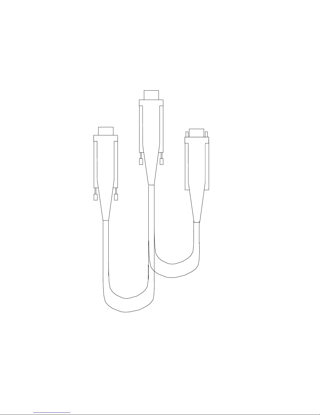
Connect to HyperConverter
Connect to Computer
Graphics Device (VGA)
To
Computer
Hyper
Converter
Connect to Computer
Display Monitor
To
Monitor
HyperConverter User’s Manual 0006-5000-503
19
Page 20

Figure 2: Cable Connection Diagram
20
HyperConverter User’s Manual 0006-5000-503
Page 21

2.4 Sun Desktop Version
Since the physical implementation of the HyperConverter is an ISA compatible board for all versions,
no board level Sun product exists. All HyperConverter Desktop Units (with appropriate input
resolution capability) will work with Sun family computers. Units ordered as Sun versions are shipped
with a Sun-compatible cable (HyperCable-SUN, 0006-2000-103). A separate PC, MAC or
Workstation cable may be ordered later.
Follow these steps to install your Desktop HyperConverter for Sun systems. If you intend to use the
HyperConverter with GenLock or component output please see Appendix C (Gen-Lock operation)
and Appendix D (Component output) for further information on these specialty items.
Turn the computer off.
Select a convenient location for the HyperConverter.
Disconnect the Computer Display from the Computer Graphics device at the Computer Graphics
device.
Connect the HyperCable-Sun's center connector (marked "HyperConverter") to the HyperConverter's
15 pin Connector.
Connect the Computer Display to the end of the HyperCable marked "Monitor".
Connect the end of the HyperCable-PC marked "Computer" to the Computer Graphics device.
Connect your Video Device to the Composite Video or S-Video output connector. (You may connect
both outputs simultaneously to the same or different Video Devices: Video is always available on both
these outputs.)
Plug the 12 VAC Power Supply's jack into the HyperConverter plug marked "Power Input".
Plug the 12 VAC Power Supply into an electrical outlet. (If you have a Universal or PAL Model, your
power supply will be a Universal Power Supply. In this case, you will have to supply an appropriate
IEC-320 compatible power cord for your country.
Turn the HyperConverter On. "On" is selected when the right side of the rocker switch is depressed.
Turn the System On. If everything is correctly installed, you will see your computer's normal power up
sequence appearing on both the Computer Display and the Video Device (if the Video Device has a
visible display).
HyperConverter User’s Manual 0006-5000-503
21
Page 22

2.5 SGI Desktop Version
Since the physical implementation of the HyperConverter is an ISA compatible board for all versions,
no board level SGI product exists. All HyperConverter Desktop Units (with appropriate input
resolution capability) will work with SGI family computers. Units ordered as SGI versions are shipped
with a SGI-compatible cable (HyperCable-SGI, 0013-2000-101). A separate PC, MAC or
Workstation cable may be ordered later.
Follow these steps to install your Desktop HyperConverter for SGI systems. If you intend to use the
HyperConverter with GenLock or component output please see Appendix C (Gen-Lock operation)
and Appendix D (Component output) for further information on these specialty items.
Turn the computer off.
Select a convenient location for the HyperConverter.
Disconnect the Computer Display from the Computer Graphics device at the Computer Graphics
device.
Connect the HyperCable-SGI's center connector (marked "HyperConverter") to the HyperConverter's
15 pin Connector.
Connect the Computer Display to the end of the HyperCable marked "Monitor".
Connect the end of the HyperCable-PC marked "Computer" to the Computer Graphics device.
Connect your Video Device to the Composite Video or S-Video output connector. (You may connect
both outputs simultaneously to the same or different Video Devices: Video is always available on both
these outputs.)
Plug the 12 VAC Power Supply's jack into the HyperConverter plug marked "Power Input".
Plug the 12 VAC Power Supply into an electrical outlet. (If you have a Universal or PAL Model, your
power supply will be a Universal Power Supply. In this case, you will have to supply an appropriate
IEC-320 compatible power cord for your country.)
Turn the HyperConverter On. "On" is selected when the right side of the rocker switch is depressed.
Turn the System On. If everything is correctly installed, you will see your computer's normal power up
sequence appearing on both the Computer Display and the Video Device (if the Video Device has a
visible display).
22
HyperConverter User’s Manual 0006-5000-503
Page 23

2.6 Workstation Desktop Version
Since the physical implementation of the HyperConverter is an ISA compatible board for all versions,
no board level workstation product exists. The Workstation Desktop version is designed to work with
all workstations that use BNC connectors to provide RGB signals to High Resolution Monitors. Since
there are a wide variety of synchronization types and levels, the HyperConverter's flexible design
enables the user to adjust the HyperConverter to various synchronization signals by configuration of
the HyperCable-BNC.
Computer video is generated in one of three ways:
5 wire - Separate signals for Red, Green, Blue, Horizontal Sync and Vertical Sync.
4 wire - Separate signals for Red, Green and Blue. Horizontal and
Vertical Sync are combined into a single signal and delivered on a separate wire.
3 wire - Separate signals for Red, Green and Blue. Horizontal and Vertical Sync are combined into a
single signal. The composite H and V signals is embedded into one or more of the Red, Green or Blue
active video signal. By industry tradition, it is expected to be found on the Green signal.
As a general rule of thumb, the following assumptions can be made about synchronization
configuration for the following popular computers:
Computer Sync Type Connector
PC 5 wire HD15
MAC 4 wire DB15
Sun 4 wire 13W3
SGI 3 wire 13W3
HP 3 wire BNC
DEC 3 wire BNC
IBM WorkStation 3 wire BNC
Turn the workstation off.
Select a convenient location for the HyperConverter.
Disconnect the workstation High Resolution Monitor from the workstation's Computer Graphics
output. (Disregard this if you are using a distribution amplifier or similar parallel path from your
computer).
HyperConverter User’s Manual 0006-5000-503
23
Page 24

Depending on the type of computer that you are using, and whether you are passing the computer
graphics signal through to a computer monitor, the connection procedure will be slightly different:
Connect the Red, Green and Blue video signals of the workstation and High Resolution Monitor to the
HyperCable-BNC's Red, Green and Blue connectors. (BNC connectors of the same color on the
HyperCable-BNC are wired together; there is no input or output end to the cable).
Connect the appropriate Sync Signals of the Workstation and High Resolution Monitor to the Sync
Signals of the HyperCable-BNC. The black connectors of the HyperCable-BNC are Horizontal and
Composite (H and V) Synchronization. The white connectors of the HyperCable-BNC are Vertical
Synchronization. (BNC connectors of the same color on the HyperCable-BNC are wired together;
there is no input or output end to the cable).
If the workstation utilizes a 5 wire Separate Sync configuration (i. e. separate Horizontal and Vertical
Sync Signals), disconnect the 75 Ohm terminator from the SEPSYNC connector of the
HyperCable-BNC.
If the workstation utilizes a 4 wire Composite Sync configuration, connect a 75 Ohm terminator to the
SEPSYNC Connector of the HyperCable-BNC.
If the Workstation has a 3 wire Sync on Green configuration (the most likely configuration), connect
one black connector to one green connector on the end of the cable nearest to the computer with the
supplied BNC T connection. Connect a 75 Ohm terminator to the SEPSYNC Connector of the
HyperCable-BNC.
Connect the end of the HyperCable-BNC marked "HyperConverter-1280" to the HyperConverter.
Connect your Video Device to the composite Video or S-Video output connector. (You may connect
both outputs simultaneously to the same or different Video Devices; Video is always available on these
outputs.)
Plug the 12 VAC Power Supply's jack into the HyperConverter plug marked "Power Input".
Plug the 12 VAC Power Supply into an electrical outlet. (If you have a Universal or PAL Model, your
power supply will be a Universal Power Supply. In this case, you will have to supply an appropriate
IEC-320 compatible power cord for your country).
Turn the HyperConverter On. "On" is selected when the right side of the rocker switch is depressed.
Turn the system On. If everything is correctly installed, you will see your workstation's normal power
sequence appearing on both the Computer Display and the Video Device) if the Video Device has a
visible display.
24
HyperConverter User’s Manual 0006-5000-503
Page 25

2.7 HyperConverter-1280R Rackmount installation
The Rackmount HyperConverter-1280 is intended for use in the permanently mounted situation of the
19 inch rack. The Rackmount HyperConverter incorporates an ISA board model HyperConverter as
its integral component. There is an additional signal conditioning board in the Rackmount
HyperConverter that requires slightly different treatment in installation than does the desktop version of
the HyperConverter.
The exact procedure for installing a Rackmount HyperConverter depends on the platform in use, the
connector configuration, the synchronization configuration and the requirement for local viewing of the
computer's output on a computer monitor. The Rackmount HyperConverter is often used in
circumstances where its input computer video is provided by a signal splitter (often referred to as a
Distribution Amplifier). Such a device splits the Computer Video signal for viewing on both a
Computer Monitor and an additional processing device (in this case the HyperConverter). In cases
where local viewing is required, without the addition of a Distribution Amplifier, the user must "pass
through" the Rackmount HyperConverter. The Rackmount HyperConverter has been designed to
accommodate this process.
Computer video is generated in one of three ways:
5 wire - Separate signals for Red, Green, Blue, Horizontal Sync and Vertical Sync.
4 wire - Separate signals for Red, Green and Blue. Horizontal and
Vertical Sync are combined into a single signal and delivered on a separate wire.
3 wire - Separate signals for Red, Green and Blue. Horizontal and Vertical Sync are combined into a
single signal. The composite H and V signals is embedded into one or more of the Red, Green or Blue
active video signal. By industry tradition, it is expected to be found on the Green signal.
As a general rule of thumb, the following assumptions can be made about synchronization
configuration for the following popular computers:
Computer Sync Type Connector
PC 5 wire HD15
MAC 4 wire DB15
Sun 4 wire 13W3
SGI 3 wire 13W3
HP 3 wire BNC
DEC 3 wire BNC
IBM WorkStation 3 wire BNC
HyperConverter User’s Manual 0006-5000-503
25
Page 26

Follow these steps to install your HyperConverter for the indicated computers. If you intend to use the
Rackmount HyperConverter with GenLock or component output, please see Appendix C (Gen-Lock
operation) and Appendix D (Component output) for further information on these specialty items.
2.7.1 Rackmount HyperConverter Installation for PCs
Turn the workstation off.
Select a convenient location for the HyperConverter.
Disconnect the PC's High Resolution Monitor from the computer.
Connect the "IN" connectors of the Rackmount HyperConverter to the PC with an HD15 to 5 BNC
Male Cable (Part # 0103-2000-100; not supplied unless specifically ordered). All 5 connectors of this
cable must be connected. Make sure that the H and V drive signals are properly oriented (typically V
is black and H is gray or white, however this color designation is at the discretion of the cable supplier
and can change). No damage will be caused by the confusion of H and V.
Set the "SEP SYNC" switch on the Back Panel of the HyperConverter to the SEP SYNC position
(Up). The position of the "SYNC ON GREEN" switch does not matter.
Connect the television compatible device. Depending on your choice of type of output video, this will
require 1, 2, or 4 BNC cables for composite, S-Video or component respectively. If you require SVideo output on a 4 pin DIN connector, use a 2 BNC Male to 4 pin DIN accessory cable (Part #
0108-2000-100; not supplied unless specifically ordered).
Plug the HyperConverter into AC power with an IEC-320 compatible power cable (American power
cable is part # 0020-2001-100; supplied with each unit). If you are outside North America, you will
have to supply an appropriate IEC-320 compatible power cord for the country that you are in.
If pass through of the Computer Graphics signal to a Computer Graphics Monitor is NOT required, set
the "75 OHM IN" switch to the 75 OHM IN position (Up). DO NOT USE the Unterminate switch
accessible from the front panel. Make sure that this switch is always in the "Terminate" (Up)
position.If pass through of the Computer Graphics signal to a Computer Graphics Monitor is required,
set the "75 OHM IN" switch to the 75 OHM OUT position (Down). DO NOT USE the Unterminate
switch accessible from the front panel. Make sure that this switch is always in the "Terminate" (Up)
position.
Connect the PC's monitor to the "OUT" BNC connectors of the Rackmount HyperConverter with a
second HD15 to 5 BNC Male Cable (Part # 0103-2000-100) and an HD-15 Gender changer (Part #
0105-2000-100, not supplied unless specifically ordered).
26
HyperConverter User’s Manual 0006-5000-503
Page 27

Turn the HyperConverter On.
Turn the Computer and Output Video Systems On. If everything is correctly installed, you will see
your computer's normal power up sequence appearing on both the Computer Display and the Video
Device (if the Video Device has a visible display).
2.7.2 Rackmount HyperConverter Installation for MACs
Turn the workstation off.
Select a convenient location for the HyperConverter.
Disconnect the MAC's High Resolution Monitor from the computer.
Connect the "IN" connectors of the Rackmount HyperConverter to the MAC with an DB15 to 4 BNC
Male Cable (Part # 0104-2000-100; not supplied unless specifically ordered). All 4 connectors of this
cable must be connected. Make sure that the Composite Sync connector of this cable is attached to the
H IN connector of the Rackmount HyperConverter.
Set the "SEP SYNC" switch on the Back Panel of the HyperConverter to the COMP SYNC position
(Down). Set the "SYNC ON GREEN" switch to the SYNC ON COMP position (Down).
Connect the television compatible device. Depending on your choice of type of output video, this will
require 1, 2, or 4 BNC cables for composite, S-Video or component respectively. If you require SVideo output on a 4 pin DIN connector, use a 2 BNC Male to 4 pin DIN accessory cable (Part #
0108-2000-100; not supplied unless specifically ordered).
Plug the HyperConverter into AC power with an IEC-320 compatible power cable (American plug
configuration is part # 0020-2001-100; supplied with each unit). If you are outside North America,
you will have to supply an appropriate IEC-320 compatible power cord for the country that you are in.
If pass through of the Computer Graphics signal to a Computer Graphics Monitor is NOT required, set
the "75 OHM IN" switch to the 75 OHM IN position (Up). DO NOT USE the Unterminate switch
accessible from the front panel. Make sure that this switch is always in the "Terminate" (Up) position.
If pass through of the Computer Graphics signal to a Computer Graphics Monitor is required, set the
"75 OHM IN" switch to the 75 OHM OUT position (Down). DO NOT USE the Unterminate switch
accessible from the front panel. Make sure that this switch is always in the "Terminate" (Up) position.
Connect the MAC's monitor to the "OUT" BNC connectors of the Rackmount HyperConverter with a
second DB15 to 4 BNC Male Cable (Part # 0104-2000-100) and an DB-15 Gender changer (Part #
0106-2000-100, not supplied unless specifically ordered). Make sure that the Composite Sync
connector of this cable is attached to the H OUT connector of the Rackmount HyperConverter.
HyperConverter User’s Manual 0006-5000-503
27
Page 28

Turn the HyperConverter On.
Turn the Computer and Output Video Systems On. If everything is correctly installed, you will see
your computer's normal power up sequence appearing on both the Computer Display and the Video
Device (if the Video Device has a visible display).
2.7.3 Rackmount HyperConverter Installation for Sun Workstations
Turn the workstation off.
Select a convenient location for the HyperConverter.
Disconnect the Sun's High Resolution Monitor from the computer.
Connect the "IN" connectors of the Rackmount HyperConverter to the Sun with a 13W3 Male to 4
BNC Male Cable (Part # 0101-2000-100; not supplied unless specifically ordered). All 4 connectors of
this cable must be connected. Make sure that the Composite Sync connector of this cable is attached
to the H IN connector of the Rackmount HyperConverter.
Set the "SEP SYNC" switch on the Back Panel of the HyperConverter to the COMP SYNC position
(Down). Set the "SYNC ON GREEN" switch to the SYNC ON COMP position (Down).
Connect the television compatible device. Depending on your choice of type of output video, this will
require 1, 2, or 4 BNC cables for composite, S-Video or component respectively. If you require SVideo output on a 4 pin DIN connector, use a 2 BNC Male to 4 pin DIN accessory cable (Part #
0108-2000-100; not supplied unless specifically ordered).
Plug the HyperConverter into AC power with an IEC-320 compatible power cable (American plug
configuration is part # 0020-2001-100; supplied with each unit). If you are outside North America,
you will have to supply an appropriate IEC-320 compatible power cord for the country that you are in.
If pass through of the Computer Graphics signal to a Computer Graphics Monitor is NOT required, set
the "75 OHM IN" switch to the 75 OHM IN position (Up). DO NOT USE the Unterminate switch
accessible from the front panel. Make sure that this switch is always in the "Terminate" (Up) position.
If pass through of the Computer Graphics signal to a Computer Graphics Monitor is required, set the
"75 OHM IN" switch to the 75 OHM OUT position (Down). DO NOT USE the Unterminate switch
accessible from the front panel. Make sure that this switch is always in the "Terminate" (Up) position.
Connect the Sun's monitor to the "OUT" BNC connectors of the Rackmount HyperConverter with a
13W3 Female to 4 BNC Male Cable (Part # 0102-2000-100; not supplied unless specifically ordered).
Make sure that the Composite Sync connector of this cable is attached to the H OUT connector of the
Rackmount HyperConverter.
28
HyperConverter User’s Manual 0006-5000-503
Page 29

Turn the HyperConverter On.
Turn the Computer and Output Video Systems On. If everything is correctly installed, you will see
your computer's normal power up sequence appearing on both the Computer Display and the Video
Device (if the Video Device has a visible display).
2.7.4 Rackmount HyperConverter Installation for SGI Workstations
Turn the workstation off.
Select a convenient location for the HyperConverter.
Disconnect the SGI's High Resolution Monitor from the computer.
Connect the "IN" connectors of the Rackmount HyperConverter to the Sun with a 13W3 Male to 4
BNC Male Cable (Part # 0101-2000-100; not supplied unless specifically ordered). Only 3 connectors
of this cable (Red, Green and Blue) must be connected.
Set the "SEP SYNC" switch on the Back Panel of the HyperConverter to the COMP SYNC position
(Down). Set the "SYNC ON GREEN" switch to the SYNC ON GREEN position (Up).
Connect the television compatible device. Depending on your choice of type of output video, this will
require 1, 2, or 4 BNC cables for composite, S-Video or component respectively. If you require SVideo output on a 4 pin DIN connector, use a 2 BNC Male to 4 pin DIN accessory cable (Part #
0108-2000-100; must be ordered).
Plug the HyperConverter into AC power with an IEC-320 compatible power cable (American plug
configuration is part # 0020-2001-100; supplied with each unit). If you are outside North America,
you will have to supply an appropriate IEC-320 compatible power cord for the country that you are in.
If pass through of the Computer Graphics signal to a Computer Graphics Monitor is NOT required, set
the "75 OHM IN" switch to the 75 OHM IN position (Up). DO NOT USE the Unterminate switch
accessible from the front panel. Make sure that this switch is always in the "Terminate" (Up) position.
If pass through of the Computer Graphics signal to a Computer Graphics Monitor is required, set the
"75 OHM IN" switch to the 75 OHM OUT position (Down). DO NOT USE the Unterminate switch
accessible from the front panel. Make sure that this switch is always in the "Terminate" (Up) position.
Connect the SGI's monitor to the "OUT" BNC connectors of the Rackmount HyperConverter with a
13W3 Female to 4 BNC Male Cable (Part # 0102-2000-100; not supplied unless specifically ordered).
Only 3 connectors of this cable (Red, Green and Blue) must be connected.
Turn the HyperConverter On.
HyperConverter User’s Manual 0006-5000-503
29
Page 30

Turn the Computer and Output Video Systems On. If everything is correctly installed, you will see
your computer's normal power up sequence appearing on both the Computer Display and the Video
Device (if the Video Device has a visible display).
2.7.4 Rackmount HyperConverter Installation for Other Workstations
Turn the workstation off.
Select a convenient location for the HyperConverter.
Disconnect the Workstation's High Resolution Monitor from the computer.
Connect the "IN" connectors of the Rackmount HyperConverter to the Sun with a 5 BNC Male to 5
BNC Male Cable (Part # 0107-2000-100; not supplied unless specifically ordered). Depending on
whether the workstation uses 3, 4 or 5 wire synchronization configuration will determine how many of
these signals you will have to hook up. Since 3 wire is the most common configuration, try this first.
No damage will occur from an improper sync connection.
The Positions of the "SEP SYNC" switch and the "SYNC ON GREEN" switches will depend on the
Sync Configuration (3, 4 or 5 wire). Since 3 wire is the most common configuration, try this first. No
damage will occur from an improper sync connection.
For 3 wire Sync, set the "SEP SYNC" switch on the Back Panel of the HyperConverter to the COMP
SYNC position (Down). Set the "SYNC ON GREEN" switch to the SYNC ON GREEN position
(Up).
For 4 wire Sync, set the "SEP SYNC" switch on the Back Panel of the HyperConverter to the COMP
SYNC position (Down). Set the "SYNC ON GREEN" switch to the SYNC ON COMP position
(Down).
For 5 wire Sync, set the "SEP SYNC" switch on the Back Panel of the HyperConverter to the SEP
SYNC position (Up). The position of the "SYNC ON GREEN" does not matter.
Connect the television compatible device. Depending on your choice of type of output video, this will
require 1, 2, or 4 BNC cables for composite, S-Video or component respectively. If you require SVideo output on a 4 pin DIN connector, use a 2 BNC Male to 4 pin DIN accessory cable (Part #
0108-2000-100; not supplied unless specifically ordered).
Plug the HyperConverter into AC power with an IEC-320 compatible power cable (American plug
configuration is part # 0020-2001-100; supplied with each unit). If you are outside North America,
you will have to supply an appropriate IEC-320 compatible power cord for the country that you are in.
30
HyperConverter User’s Manual 0006-5000-503
Page 31

If pass through of the Computer Graphics signal to a Computer Graphics Monitor is NOT required, set
the "75 OHM IN" switch to the 75 OHM IN position (Up). DO NOT USE the Unterminate switch
accessible from the front panel. Make sure that this switch is always in the "Terminate" (Up) position.
If pass through of the Computer Graphics signal to a Computer Graphics Monitor is required, set the
"75 OHM IN" switch to the 75 OHM OUT position (Down). DO NOT USE the Unterminate switch
accessible from the front panel. Make sure that this switch is always in the "Terminate" (Up) position.
Connect the workstation's monitor to the "OUT" BNC connectors of the Rackmount HyperConverter
with second 5 BNC Male to 5 BNC Male Cable (Part # 0107-2000-100; not supplied unless
specifically ordered). Connect the appropriate connectors for 3, 4 or 5 wire sync.
Turn the HyperConverter On.
Turn the Computer and Output Video Systems On. If everything is correctly installed, you will see
your computer's normal power up sequence appearing on both the Computer Display and the Video
Device (if the Video Device has a visible display).
HyperConverter User’s Manual 0006-5000-503
31
Page 32
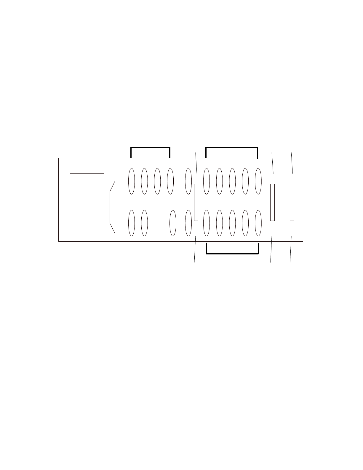
Power RS232
Input
75 Ohm
Component Output Non-Interlaced Input
In
Sync on
Green
Sep
Sync
RS422
R
V
Y
B
U
Y
CComposite
Output
S
House
Sync
R G B H VG
R G B
75 Ohm
Out
H V
Non-Interlaced Pass Through
Sync on
Comp
Comp
Sync
32
HyperConverter User’s Manual 0006-5000-503
Page 33

Figure 3: Rackmount Version Backplate
HyperConverter User’s Manual 0006-5000-503
33
Page 34

3.0 Switch Settings and Adjustments
There are several switch settings that are available on the HyperConverter. Functions that require
instant access are available from the outside of all version of the HyperConverter. The board version's
switches are accessible through the PC backplate. The desktop model's switches may be accessed
through the back end of the metal enclosure. The rack mount version's switches may be accessed
through the control access plate (front side of the unit).
3.1 Externally Accessible Switches
The externally accessible switches are designated with an "On" direction arrow, and are labelled such
that the indicated function is active when the switch is in the "On" position. Their functionality and
position is identical in both board and desktop versions. It is not necessary to power down or reset the
computer, monitor, HyperConverter or video device when adjusting these switches. From left to right
with the board or box right side up (or from bottom to top with a board mounted in the computer)
these switches are:
3.1.1 UnderScan
This switch selects UnderScan. An "UnderScanned" picture slightly shrinks the whole display such
that information in the corners is visible. Select UnderScan "On" when you have text or detail oriented
pictures that requires you to preserve fine detail in the corner regions of the display. An
"OverScanned" picture fills the entire area of the screen, which is the natural way of presenting material
in television. Use OverScan to present image and animation oriented material.
3.1.2 Un-Terminate VGA
This switch disconnects the HyperConverter's termination resistors from the computer's RGB output
lines. Set this switch to "On" (unterminated) when you are using the HyperConverter with a computer
monitor. (This is the usual mode of operation.) If you want to view the HyperConverter's output on
your video device alone, (i. e. no computer monitor in your system), set this switch to "Off"
(terminated position).
Rackmount HyperConverter Users take note: The termination resistors for the rack mount unit are in
BNC signal interface board on the back panel of the Rackmount HyperConverter. Termination
adjustment for the Rackmount HyperConverter should be effected by adjusting the "75 Ohm In" switch
on the Back Panel of the Rackmount HyperConverter. The "Unterminate VGA" switch of the
Rackmount HyperConverter should always be set to the Terminate Position ("Off").
34
HyperConverter User’s Manual 0006-5000-503
Page 35

3.1.3 Freeze Frame
This switch freezes the output video of the HyperConverter. Set this switch to "On" to freeze the
picture.
3.1.4 Sharpness (Flicker Reduction Filter)
This switch selects the operation of the Flicker Reduction Filter. Set this switch to "On" to disable the
Flicker Reduction Filter. Set this switch to "On" to maximize the vertical sharpness. (Use maximum
sharpness for displays that have already been prepared for Interlaced operation, i. e. photo-realistic
image oriented presentations or animations). Set this switch to "Off" to reduce the flicker of Text and
GUI oriented applications (such as the Windows Desktop).
3.1.5 PAL
This switch selects PAL operation (Universal models). Set this switch to "On" for PAL (European)
operation. Set this switch to "Off" for NTSC (American) operation.
HyperConverter User’s Manual 0006-5000-503
35
Page 36
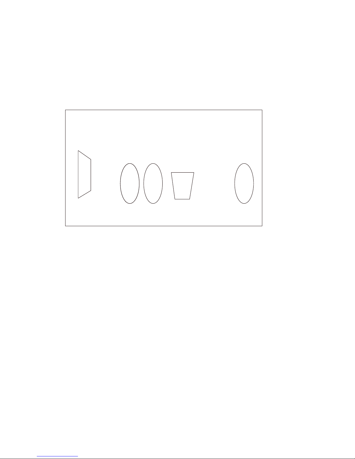
RS232/
RS422
NTSC/PAL
Output
S-Video
Output
Power
HyperConverter
Input
Figure 4: Desktop Version Backplate
36
HyperConverter User’s Manual 0006-5000-503
Page 37

3.2 Card Edge Adjustments
These adjustments may be accessed on the top side of a Board model HyperConverter while it is
operational in its slot. Some are also accessible through the side of a Desktop model HyperConverter.
Some of these adjustments (indicated below) should only be modified with professional test
equipment. Other adjustments (also indicated below) should be made ONLY by Focus Enhancements
service personnel.
3.2.1 Sync Threshold VR93
Not accessible to Desktop or Rackmount Model Users without removal of the cover. This control
determines the voltage threshold level for separate synchronization. It is used to adjust to S-VGA sync
signals that are 75 Ohm terminated or otherwise weak.
3.2.2 B-Y Black Reference VR70
Not accessible to Desktop Model or Rackmount Users without removal of the cover. This control
adjusts the HyperConverter's internal B-Y Black Reference level. This adjustment should be made
only by Focus Enhancements service personnel.
3.2.3 R-Y Black Reference VR640
Not accessible to Desktop Model or Rackmount Users without removal of the cover. This control
adjusts the HyperConverter's internal R-Y Black Reference level. This adjustment should be made
only by Focus Enhancements service personnel.
3.2.4 Vertical Position VR60
This control adjusts the Vertical Position of the displayed information.
3.2.5 Vertical Size VR53
This control adjusts the Vertical Size of the displayed information.
3.2.6 Horizontal Size VR46
This control adjusts the Horizontal Size of the displayed information.
HyperConverter User’s Manual 0006-5000-503
37
Page 38

3.2.7 Horizontal Position VR39
This control adjusts the Horizontal Position of the displayed information.
3.2.8 Gen-Lock Phase VR201
This control adjusts the relative color phase with respect to a GenLock Master signal. Use this control
only when using the GenLock capability of the HyperConverter.
3.2.9 Gen-Lock Position VR30
This control adjusts the relative picture position with respect to a GenLock Master picture position.
Use this control only when using the GenLock capability of the HyperConverter.
3.2.10 Y Video Level VR22
Not accessible to Desktop Model Users without removal of the cover. This control adjusts the gain of
the Y video component.
3.2.11 U Video Level VR16
Not accessible to Desktop Model Users without removal of the cover. This control adjusts the gain of
the U video component.
3.2.12 V Video Level VR21
Not accessible to Desktop Model Users without removal of the cover. This control adjusts the gain of
the V video component.
3.2.13 Luminance Black Reference VR500
Not accessible to Desktop Model or Rackmount Users without removal of the cover. This control
adjusts the HyperConverter's internal Luminance Black Reference level. This adjustment should be
made only by Focus Enhancements service personnel.
38
HyperConverter User’s Manual 0006-5000-503
Page 39

3.3 Internal Adjustments and Jumpers
These adjustments and jumpers are accessible only by removing board level HyperConverters from
their PC slots or by removing the top of Desktop HyperConverters. Some of these adjustments
(indicated below) should only be modified with professional test equipment. Other adjustments (also
indicated below) should be made ONLY by Focus Enhancements service personnel.
3.3.1 17.734476 MHz. Crystal Adjustment VC40
This control adjusts the frequency of the 17.734476 MHz Crystal. This adjustment should be made
only by Focus Enhancements service personnel.
3.3.2 14.31818 MHz. Crystal Adjustment VC33
This control adjusts the frequency of the 14.31818 MHz Crystal. This adjustment should be made only
by Focus Enhancements service personnel.
3.3.3 YUV-RGB Jumpers JP3
Jumper JP3 determines whether RGB or YUV component signals will appear on Connector P1 (and
consequently at the RGB outputs of the HyperCable-PC-RGB, HyperCable-MAC-RGB, HyperCableSUN-RGB, etc.). The HyperConverter provides a three component output (RGB or YUV) signal on
Pins 10, 5 and 9 of connector P1 respectively. (A Composite Sync signal is supplied on Pin 12). For
RGB operation Pin 2 to Pin 3, Pin 5 to Pin 6, Pin 8 to Pin 9, Pin 11 to Pin 12, Pin 14 to Pin 15, Pin 17
to Pin 18 of JP3 should be connected together. (This is the factory default position). (Please note:
Pins 16, 17 and 18 of jumper JP3 exist only on HyperConverter fab # 0006-1100-500 and higher). For
YUV operation Pin 1 to Pin 2, Pin 4 to Pin 5, Pin 7 to Pin 8, Pin 10 to Pin 11, Pin 13 to Pin 14, Pin 16
to Pin 17, of JP3 should be connected together. (Please note: Pins 16, 17 and 18 of jumper JP3 exist
only on HyperConverter fab # 0006-1100-500 and higher).
If your YUV video equipment requires no 7.5 IRE setup, remove the jumper connecting Pin 1 to Pin 2
of JP3. Otherwise this jumper should be installed.
HyperConverter User’s Manual 0006-5000-503
39
Page 40

3.3.4 Gamma Correction Jumpers JP5, JP6, JP7
These jumpers determine whether the HyperConverter will compensate for monitor Non-Linearities by
applying a Gamma Correction Factor. For Linear HyperConverter output (No Gamma Correction)
Pin 2 should be connected to Pin 3 on all three of these jumpers. (This is the factory default position).
For a Gamma Correction Factor of 2.4, Pin 1 should be connected to Pin 2 on all three of these
jumpers.
3.3.5 Clamp Signal Source JP4
This jumper determines where the HyperConverter will derive its input clamping signal from. If Pin 1
is connected to Pin 2, the clamp signal will be derived from the HyperConverter's sync separator. If
Pin 5 is connected to Pin 6, the clamp signal will be derived from the rising edge of horizontal sync.
Pin 3 connected to Pin 4 is a reserved configuration. The factory default is Pin 5 connected to Pin 6.
3.3.6 Sync on Green JP8
This jumper selects composite sync from the green input (Pin 2 of connector P1). This jumper is
only operational when composite sync is selected.
3.3.7 Sync on H-Drive JP9
This jumper selects composite sync from the horizontal drive input (Pin 13 of connector P1). This
jumper is only operational when composite sync is selected.
3.3.8 Composite Sync Override JP10
This jumper permanently selects composite sync.
3.3.9 YUV M2 JP12
This jumper is used to determine the level of component output. For M2 style and PAL B output, Pin
1 to Pin 2 and Pin 3 to Pin 4 of JP12 should be connected. For BetaCam style output, no pins should
be connected.
40
HyperConverter User’s Manual 0006-5000-503
Page 41

3.3.10 GenLock Phase JP13
This jumper is used to change the color phase by 180 degrees when in GenLock mode. Default
configuration is Pin 1 to Pin 2. To change phase by 180 degrees, connect Pin 2 to Pin 3.
3.3.11 PLL Voltage VC197
This variable capacitor adjusts PLL charge pump baseline voltage level. This adjustment should be
made only by Focus Enhancements service personnel.
3.3.12 U Subcarrier Null VR265
This potentiometer adjusts the null point of the internal U signal. This adjustment should be made only
by Focus Enhancements service personnel.
3.3.13 V Subcarrier Null VR507
This potentiometer adjusts the null point of the internal V signal. This adjustment should be made only
by Focus Enhancements service personnel.
3.3.14 PAL Color Balance VR505
This potentiometer adjusts the null point of the internal V signal for PAL only. This adjustment should
be made only by Focus Enhancements service personnel.
3.3.15 Encoder Y Level VR273
This potentiometer adjusts the Luminance Gain for Composite Video Output. This adjustment should
be made only by Focus Enhancements service personnel.
3.3.16 Encoder U Level VR274
This potentiometer adjusts the U Channel Gain for Composite Video Output. This adjustment should
be made only by Focus Enhancements service personnel.
HyperConverter User’s Manual 0006-5000-503
41
Page 42
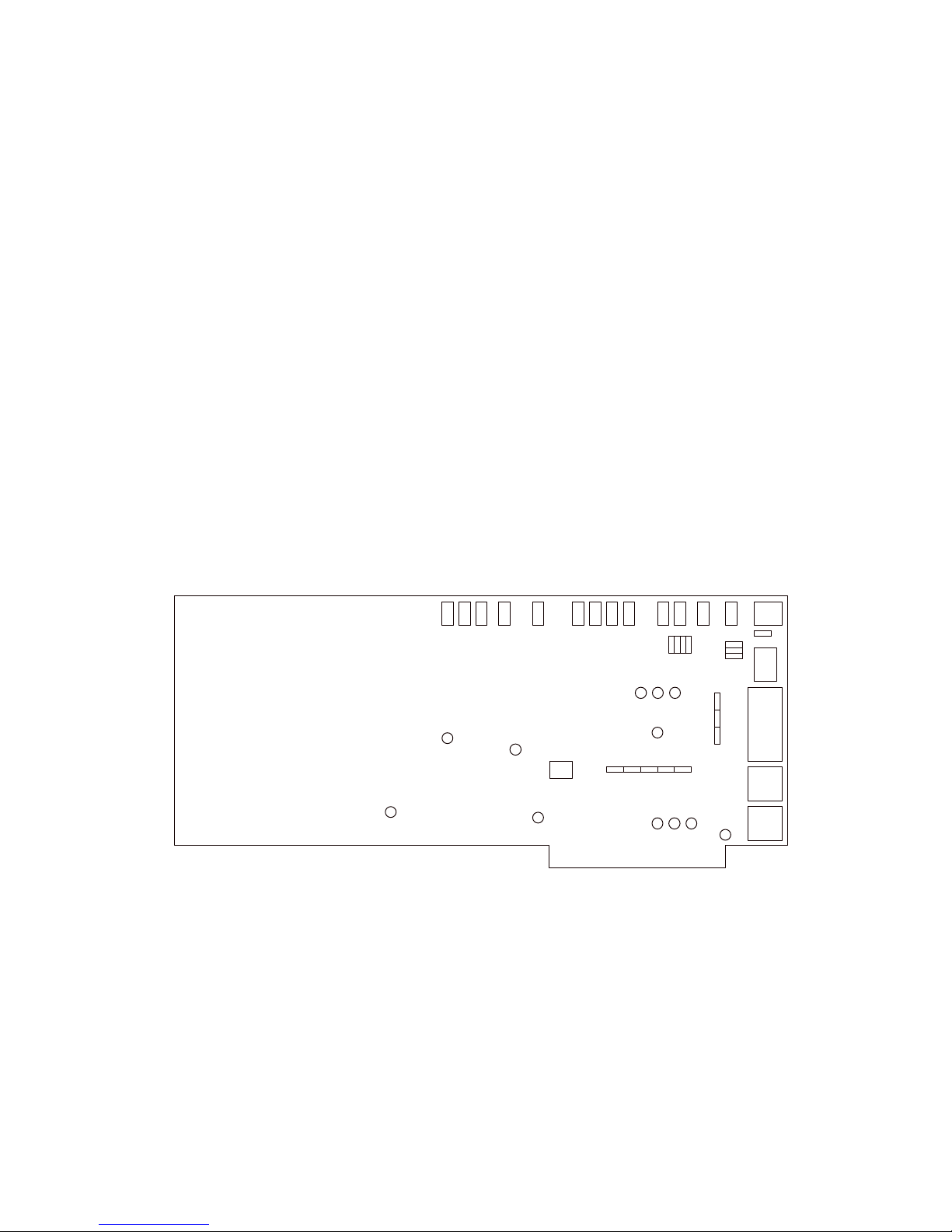
3.3.17 Encoder V Level VR275
This potentiometer adjusts the V Channel Gain for Composite Video Output. This adjustment should
be made only by Focus Enhancements service personnel.
3.3.18 Burst Trim VR530
This potentiometer adjusts the Amplitude of the Color Burst Signal. This adjustment should be made
only by Focus Enhancements service personnel.
3.3.19 Burst Position VR270
This potentiometer positions the color burst in reference to the trailing edge of Horizontal Sync.. This
adjustment should be made only by Focus Enhancements service personnel.
VR21
VR16
VR22
VR30
VR201 VR39
VR46
VR53
VR60
VR70
VR500
VR640
VR93
VC197
VC33
VC40
VR248
JP12
VR507
JP4
VR265
VR270
JP3
VR274
VR505
VR275
JP8
JP9
JP10
JP5
JP6
JP7
VR273
JP13
P1
VR530
42
HyperConverter User’s Manual 0006-5000-503
Page 43

Figure 5: Adjustments and Jumpers
HyperConverter User’s Manual 0006-5000-503
43
Page 44

4.0 Hyperformance Utility Software
All IBM PC versions of HyperConverter models come with the Hyperformance Test Software. A
Macintosh version is currently being developed. This software is not necessary for the operation of the
HyperConverter, but is useful in the testing and evaluation of the HyperConverter and the graphics
devices that you intend to record to video.
4.1 IBM PC Version
The IBM version of the Hyperformance Software consists of a DOS application program with some
sample images.
The diskette contains the following files and directories:
Hyperformance Test Software Disk
HYPER.EXE Hyperformance Test Software
PICTURE8.PCX A 256 color image
PICTURE4.PCX A 16 color image
4.1.1 Installing and Running Hyperformance Tests Software
To install the software, copy the contents of the Hyperformance PC Test Software diskette to your
hard disk, as follows:
COPY A:*.* C: or B:*.* C:
This command should copy HYPER.EXE, PICTURE8.PCX, and PICTURE4.PCX to your hard disk.
To execute the program, type "HYPER".
44
HyperConverter User’s Manual 0006-5000-503
Page 45

4.1.2 The Main Menu
Upon execution, the utility software displays the following menu:
HYPERCONVERTER UTILITY SOFTWARE
1 Text Mode 720 x 400 (Mode 3 hex)
2 16 color 640 x 350 (Mode 10 hex)
3 16 color 640 x 480 (Mode 12 hex)
4 256 color 320 x 200 (Mode 13 hex)
5 16 color VESA 800x600 (Mode 102h)
6 256 color VESA 800x600 (Mode 103h)
7 16 color VESA 1024x768 (Mode 104h)
8 256 color VESA 1280 x 1024 (Mode 107H)
I Images
C Change Menu Color
S Clear Screen
M Display Menu
Q Quit
HyperConverter User’s Manual 0006-5000-503
45
Page 46

Commands 1-8 set the Video Mode. The current video mode is always displayed at the bottom of the
screen. The default video mode is Mode 12 Hex: 16 Color, 640 columns by 480 rows.
I clears the screen and displays the Image Menu (see below).
C clears the screen and displays a menu which allows you to select
a different color for the menus (press ESC to leave this
menu without changing the menu color).
S clears the VGA screen of image and text.
M redisplays the menu.
Q leaves the utility software and returns to DOS.
4.1.3 The Image Menu
HYPERCONVERTER TEST IMAGES
T Page of Text
C Color Bars
H Chirp
P Pattern
I Picture
A Ramp
K Chroma Key Chart
M Menu
S Clear Screen
R Return
T Displays a Page of Text.
C Displays eight vertical color bars.
H Displays a Chirp Pattern.
P Displays a Complex Black and White
Pattern.
I Displays a 16 or 256 color picture
(the full picture is seen only in the
1024 x 768 mode; smaller resolutions
display the upper left hand corner of
the picture).
A Displays a 16 or 256 grey shades ramp.
K Displays a 16 or 256 color grid.
M Redisplays the Image Menu.
S Clears the screen.
R Returns to the Main Menu.
46
HyperConverter User’s Manual 0006-5000-503
Page 47

4.1.4 Hyperformance Utility Software Error Messages
4.1.4.1 Not a Legal Command in TEXT MODE
The Page of Text is the only Image that can be displayed in Text mode. This error message will be
displayed if you try to display any of the other Images in Text mode.
4.1.4.2 Picture8.PCX Not Found!
Picture8.PCX contains the Picture displayed in the 256 color modes. If this error message occurs,
make sure the file PICTURE8.PCX is present in the current directory.
4.1.4.3 Picture4.PCX Not Found !
Picture4.PCX contains the Picture displayed in the 16 color modes. If this error message occurs, make
sure the file PICTURE4.PCX is present in the current directory.
4.1.4.4 VESA Version n.n VESA CALL FAILED
This error occurs when the VESA driver with the indicated version number has been installed, but a
call to the VESA software returns an error code. It indicates an incompatibility between the VESA
driver and the VGA card.
4.1.4.5 VESA Driver Not Installed
The utility software uses the VESA TSR in the 1024x768 and 800x600 modes. If your attempt to use
these modes results in this error message, make sure you have installed the VESA TSR (see above).
HyperConverter User’s Manual 0006-5000-503
47
Page 48

5.0 Troubleshooting
In addition to providing the most cost efficient Hi-Res to Video Conversion available, the
HyperConverter product family is also designed to be applied in the "Real World". There is a built in
tolerance to input Computer Graphics devices which do not meet their own specifications. With one of
these devices, your HyperConverter will adapt to the best estimate of the intended performance of the
device. The user will be unaware that this is happening. There are, however, some limitations. This
section is intended to help you recognize and correct these situations.
5.0.1 Blank or Frozen NTSC or PAL Screen on Start-Up
If you see a Blank or Frozen (sometimes with a horizontally oriented fixed pattern) NTSC/PAL screen
on startup, check that the HyperConverter is properly powered-up and connected.
5.0.2 Shimmering NTSC or PAL Video
This indicates that the input Computer Graphics device is using an Interlaced output format. The
HyperConverter is not compatible with Interlaced Computer Graphics devices. Depending on the
type of Computer Graphics device in use, there are a number of things that may be done.
The IBM 8514 and original XGA both use a 44 Hz. Interlaced video format in their 1024 x 768
modes; at 640 x 480 they both use VGA compatible 60 Hz. Non-Interlaced output. Therefore, if you
are using a HyperConverter with an IBM XGA or 8514, you should not use 1024 x 768 output modes.
A number of manufacturers make software compatible versions of XGA which support a 1024 x 768
Non-Interlaced output format. The HyperConverter is compatible with these devices.
The IBM XGA-2 has 1024 x 768 Non-Interlaced modes. These modes are only engaged if properly
invoked and if a 9715 or 9515 IBM monitor is used.
If you are using an S-VGA and the shimmering screen appears in 1024 x 768 operation, the solution
may be much simpler. Many S-VGA cards are switch selectable to provide both Non-Interlaced and
Interlaced output. Check the Operator's Manual of your S-VGA card to determine how to configure it
for Non-Interlaced operation. Make sure that you also consult the Operator's Manual of your monitor
to ensure that it is capable of operation with the new, Non-Interlaced video format.
48
HyperConverter User’s Manual 0006-5000-503
Page 49

5.0.3 "Scrambled" NTSC Output
If the NTSC/PAL output appears scrambled, the likely cause of the problem is the improper
connection of the Hyper-Cable. Ensure that the HyperConverter and Computer ends of the
HyperCable are plugged into the proper device.
5.0.4 "Dim" NTSC or S-Video Output
If you are using the HyperConverter with a VGA monitor and the NTSC/PAL output appears dim,
check the position of the Un-Terminate Switch (see Section 3.1.2). If a VGA monitor is used, the
Un-Terminate Switch should be "On" (Down).
5.0.5 "Bright" NTSC or S-Video Output
If you are using the HyperConverter WITHOUT a VGA monitor and the NTSC/PAL output appears
overly bright, check the position of the Un-Terminate Switch (see Section 3.1.2). If a VGA monitor is
not used, the Un-Terminate Switch should be "Off" (Up).
5.0.6 Excessive Flicker
If the NTSC/PAL output flickers excessively, the Sharpness switch may be in the incorrect position.
See section 3.1.4 to correctly set this switch.
Some Residual Flicker is to be expected in NTSC/PAL video equipment. This is due to the interlaced
nature of the NTSC and PAL video signals and is unavoidable.
HyperConverter User’s Manual 0006-5000-503
49
Page 50

Appendix A - Statement of Warranty
Focus Enhancements warrants each product manufactured by it to be free from defects in
workmanship under normal use and service for twelve months after shipment.
All products found to be defective will be repaired or replaced at Focus Enhancements's option, upon
examination of the defective unit. The customer will bear shipping charges of the defective unit to
Focus Enhancements. Focus Enhancements will bear shipping charges of the repaired or replaced unit
back to the customer. A replacement unit will only be shipped after the receipt of the defective unit.
No returns will be accepted without an advance RMA (Return of Materials Authorization).
50
HyperConverter User’s Manual 0006-5000-503
Page 51

Appendix B - Hyperformance Utility Software License
Focus Enhancements Corporation grants the user a 99 year license to use and reproduce the
Hyperformance Utility Software. No restrictions in copying or using the software or its reproduced
images are implied except that any video taped reproduction of any image developed or displayed by
the Hyperformance Utility Software must be reproduced using a Focus Enhancements
HyperConverter.
HyperConverter User’s Manual 0006-5000-503
51
Page 52

Appendix C - GenLock
All versions of the HyperConverter can Gen-Lock to a black burst, active video or TTL level external
reference signal. Our usage of the word GenLock is the usage understood by professional Television
Engineers. The HyperConverter will lock Vertically, Horizontally and in color phase to the external
reference signal. All Overlay, Chroma-Key, mixing functions must be accomplished by additional
devices.
Although all models of the HyperConverter support GenLock as an internal feature, you must use the
HyperConverter with an appropriate cable to get at the GenLock function. Cables which provide this
feature exist for all 5 platform and connector configurations of the HyperConverter (PC, MAC, Sun,
SGI, Other BNC workstation). The GenLock cables provide an electrical pass through of the external
reference signal (i. e. the Gen-Lock signal is passed from one BNC connector to the other, without a
buffer amplifier or other intervening circuitry). You can obtain the GenLock feature with or without
component support. (Please see the next section.)
The suggested way to align GenLock is as follows:
Make sure that the HyperConverter provides a properly aligned picture with respect to an ordinary
television raster. (Since you have control over Horizontal and Vertical Size and Position, all 4 of these
parameters must be properly aligned with a television raster before attempting GenLock).
Adjust the GenLock Horizontal position for correct position of the converted video signal at the
mixing point.
Adjust the GenLock Color Phase for the correct color phase of the converter video signal at the mixing
point.
52
HyperConverter User’s Manual 0006-5000-503
Page 53

Appendix D - Component output
All versions of the HyperConverter support several forms of component output. The HyperConverter
can be configured for Betacam, M2, and RGB (with or without 7.5 IRE units of video setup). In
addition, component output synchronization may be provide as a separate, composite sync signal (4
wire) or as composite sync signal on the green output (3 wire).
Although all models of the HyperConverter support component output as an internal feature, you must
use the HyperConverter with an appropriate cable to get at this function. Cables which provide the
component output feature exist for all 5 platform and connector configurations of the HyperConverter
(PC, MAC, Sun, SGI, Other BNC workstation).
HyperConverter User’s Manual 0006-5000-503
53
Page 54

Appendix E - FCC Compliance Statement
Note: This equipment has been tested and found to comply with the limits for a Class B Digital Device
pursuant to Part 15 of the FCC Rules. There limits are designed to provide reasonable protection
against interference if installed and operated properly in a commercial environment. This equipment
generates, uses and can radiate radio frequency energy, and if not properly installed and used in
accordance with the instructions in this manual, may cause harmful interference to radio
communications. Operation of this equipment in a residential area is likely to cause harmful
interference in which case the user will be required to correct the interference at his own expense.
Only peripherals (computer I/O devices, terminals, printers. etc.) tested and complying with Class B
limits should be attached to this device with shielded I/O cables.
Finally, any changes or modifications to the equipment by the user not expressly approved by the
grantee or manufacturer could void the user's authority to operate such equipment.
54
HyperConverter User’s Manual 0006-5000-503
 Loading...