

Page 1

Harmony
2ES and 4ES
User Manual
Page 2

Trademarks
The Focus Enhancements, Visual Circuits, and Harmony logos are
trademarks in the United States and other countries. All other
products, services or company names mentioned herein are
claimed as trademarks and trade names by their respective
companies.
© Focus Enhancements, 1999-2005. All rights reserved.
No portion of this manual may be copied by any means without the
prior consent of Visual Circuits.
Focus Enhancements
5155 East River Road, Suite 401
Minneapolis, MN 55421 USA
http://www.visualcircuits.com
Publication Number: 813-0048b
All specifications, notices and warnings are subject to change
without notice.
Page 3
i
Class A Statement
FCC Part 15 (EN61000-3-2)
This equipment has been tested and found to comply with the
limits for a Class A digital device, pursuant to Part 15 (EN61000-3-
2) of the FCC Rules. These limits are designed to provide
reasonable protection against harmful interference when the
equipment is operated in a commercial environment. This
equipment generates, uses, and can radiate radio frequency
energy and, if not installed and used in accordance with this
instruction manual, may cause harmful interference to radio
communications. Operation of this equipment in a residential area
is likely to cause harmful interference in which case the user will
be required to correct the interference at his or her own expense.
The Harmony 4ES complies with Part 15 (EN61000-3-2) of the
FCC rules.
Operation is subject to the following two conditions:
1. This device may not cause harmful interference.
2. This device must accept any interference that may cause undesired
operation.
Industry Canada
This Class A digital apparatus meets all requirements of the
Canadian Interference-Causing Equipment Regulations.
Cet appareil numerique de la classe A respecte toutes les
exigences du Regulement sur le materiel brouilleur du Canada.
Changes or modifications to this unit not expressly
approved by the party responsible for compliance
could void the user’s authority to operate the
equipment.
Page 4
ii
EMC and Safety Directive Compliance
The CE mark is affixed to this Visual Circuits Corporation product
to confirm compliance with the following European Community
Directives:
Council Directive 89/336/EEC of 3 May 1989 on the approximation
of the laws of Member States relating to electromagnetic
compatibility.
And
Council Directive 73/23/EEC of 19 February 1973 on the
harmonization of the laws of Member States relating to electrical
equipment designed for use within certain voltage limits:
Each amended by Council Directive 93/68/EEC of 22 July 1993 on
the harmonization of CE marking requirements.
Class A Warning (EN55024, EN55022)
In a domestic environment this product may cause radio
interference in which case the user may be required to take
adequate measures.
All specifications are subject to change without notice.
Page 5

iii
CONTENTS
Overview . . . . . . . . . . . . . . . . . . . . . . . . . . . . . . . . . . . . . . . 1
Harmony 2ES and 4ES . . . . . . . . . . . . . . . . . . . . . . . . . . . . . . 1
Technical Description . . . . . . . . . . . . . . . . . . . . . . . . . . . . . . . 2
Audio/Video Distribution . . . . . . . . . . . . . . . . . . . . . . . . . . . . . 3
Application Interface (API) for the Harmony 4ES . . . . . . . . . . 4
Installation Guide . . . . . . . . . . . . . . . . . . . . . . . . . . . . . . . . 5
Card Installation . . . . . . . . . . . . . . . . . . . . . . . . . . . . . . . . . . . 6
Cable Installation (A/V Breakout) . . . . . . . . . . . . . . . . . . . 7
Driver Installation for Windows 2000/2003/NT 4.0/XP . . . 8
Starting Playback . . . . . . . . . . . . . . . . . . . . . . . . . . . . . . . . . 18
Obtaining File Information . . . . . . . . . . . . . . . . . . . . . . . . . . . 20
Using On Screen Displays . . . . . . . . . . . . . . . . . . . . . . . . . . 21
Testing Genlock and External Audio/Video . . . . . . . . . . . . . 22
Editing Driver Settings . . . . . . . . . . . . . . . . . . . . . . . . . . . 23
Driver Editing Utility: Harmony VccReg.exe . . . . . . . . . . . . . 23
Common Driver Parameters. . . . . . . . . . . . . . . . . . . . . . 23
General . . . . . . . . . . . . . . . . . . . . . . . . . . . . . . . . . . 24
Performance. . . . . . . . . . . . . . . . . . . . . . . . . . . . . . . 25
Audio/Video . . . . . . . . . . . . . . . . . . . . . . . . . . . . . . . 28
Special . . . . . . . . . . . . . . . . . . . . . . . . . . . . . . . . . . 29
Multi-Card Servers . . . . . . . . . . . . . . . . . . . . . . . . . . . . . . 31
Multi-Threading and Drive Mapping . . . . . . . . . . . . . . . . . . . 31
MaxDisks drive parameter . . . . . . . . . . . . . . . . . . . . . . . 31
Page 6

iv
Contents
Encoding Parameters . . . . . . . . . . . . . . . . . . . . . . . . . . . . 33
Encoding Recommendations . . . . . . . . . . . . . . . . . . . . . . . . 34
Cross-Channel Synchronization . . . . . . . . . . . . . . . . . . . 37
Cross-channel Sync Commands . . . . . . . . . . . . . . . . . . . . . 38
mpgPlay, mpgPlayAll, mpgStop, mpgStopAll. . . . . . . . . 38
Troubleshooting . . . . . . . . . . . . . . . . . . . . . . . . . . . . . . . . 39
Overview . . . . . . . . . . . . . . . . . . . . . . . . . . . . . . . . . . . . . . . 39
Server Setup Check . . . . . . . . . . . . . . . . . . . . . . . . . . . . 39
Getting Started . . . . . . . . . . . . . . . . . . . . . . . . . . . . . . . . 40
Troubleshooting Tips . . . . . . . . . . . . . . . . . . . . . . . . . . . . . . 41
BIOS Settings . . . . . . . . . . . . . . . . . . . . . . . . . . . . . . . . . 41
Blue screen. . . . . . . . . . . . . . . . . . . . . . . . . . . . . . . . . . . 41
'' Harmony Driver not found!'' when Vidserve started . . 42
No video or audio output . . . . . . . . . . . . . . . . . . . . . . . . 42
Stuttering files during Playback . . . . . . . . . . . . . . . . . . . 43
"Latent Images" or "Flashing" during playback. . . . . . . . 44
SMPTE time codes are not recognized properly . . . . . . 44
Video blocks or stutters when starting playback. . . . . . . 44
Overall block or distorted playback. . . . . . . . . . . . . . . . . 45
Problems using the API . . . . . . . . . . . . . . . . . . . . . . . . . 45
Mouse lags and overall poor system performance. . . . . 45
MPEG will not play on mapped network drive . . . . . . . . 45
Harmony Vidserve does not work at all . . . . . . . . . . . . . 46
All channels pause when new file is started . . . . . . . . . 46
No audio . . . . . . . . . . . . . . . . . . . . . . . . . . . . . . . . . . . . . 46
More than one board will not play . . . . . . . . . . . . . . . . . 46
PCIX System Hangs with Harmony . . . . . . . . . . . . . . . . 46
Contacting Focus Enhancements . . . . . . . . . . . . . . . . . . 47
Support for Users . . . . . . . . . . . . . . . . . . . . . . . . . . . . . . . . . 47
Before calling for support . . . . . . . . . . . . . . . . . . . . . . . . 47
Page 7

v
Contents
Support for VARs and Distributors . . . . . . . . . . . . . . . . . . . . 48
Contact Information for VARs and Distributors. . . . . . . . 48
VARs and Distributors Returning Materials to Focus . . . . . . 49
Appendix . . . . . . . . . . . . . . . . . . . . . . . . . . . . . . . . . . . . . . 51
AV Breakout Cables . . . . . . . . . . . . . . . . . . . . . . . . . . . . . . . 52
Pinouts . . . . . . . . . . . . . . . . . . . . . . . . . . . . . . . . . . . . . . 54
Specifications . . . . . . . . . . . . . . . . . . . . . . . . . . . . . . . . . . . . 55
Vidcom Serial Command Interface . . . . . . . . . . . . . . . . . . . . 57
Connecting directly to the Server . . . . . . . . . . . . . . . . . . 57
Vidcom Interface. . . . . . . . . . . . . . . . . . . . . . . . . . . . . . . 57
Vidcom Supported Serial Commands . . . . . . . . . . . . . . 58
Index. . . . . . . . . . . . . . . . . . . . . . . . . . . . . . . . . . . . . . . . . . . 1
Page 8

vi
Page 9
1
OVERVIEW
Harmony 2ES and 4ES
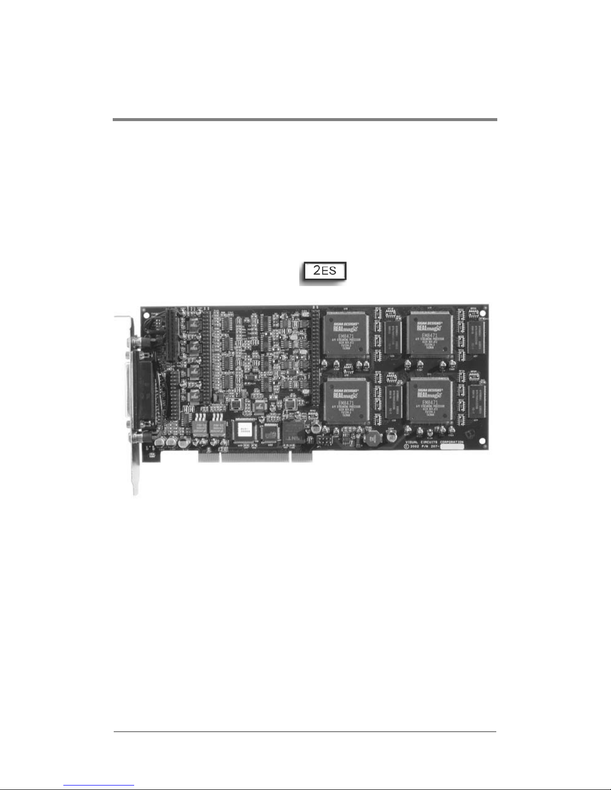
The Harmony 2ES and 4ES share similar features and capabilities.
The primary difference between the two cards is the number of
channels they provide: the 2ES has two channels and the 4ES has
four. For simplicity, this manual refers to either the 4ES or
Harmony. Where differences between the two cards do occur, an
icon indicates 2ES information.
Figure 1 Harmony 4ES Card
Page 10
Overview
2
Technical Description
The Visual Circuits Harmony 2ES™ and Harmony 4ES™ cards are
PCI MPEG decoder cards that support respectively, two or four
independent outputs (channels) of high-quality video playback.
These Harmony cards have their own unique driver and API
structure designed to offer maximum compatibility with Visual
Circuits ReelTime series cards.
The Harmony 4ES simultaneously outputs composite and highquality S-video, along with either Dolby Digital audio or Stereo
PCM audio via S/PDIF. Alternately, Harmony 4ES can also output
RGB (sync on green) or component video.
The Harmony also supports a dynamic On Screen Display (OSD)
of 256 colors with varying degrees of transparency. Since all video
decoding is performed through hardware, not only can a single
four-channel card run in four independent outputs, but six cards are
supported in the same server as well. The Windows 2000/NT
driver also includes a Software Developers Kit (SDK) with
libraries and a sample program allowing flexibility and
customization.
Maximum Number of Harmony Cards in a Server
The maximum number of Harmony cards supported by a server
depends on the method used to configure their operation.
6 Harmony with maximum of 24 Channels
Standard implementation using Vidserve allows for a maximum
number of 6 Harmony cards with a possible total of 24 channels.
8 Harmony Cards with maximum of 32 Channels
Using the Serial Commands interface and information provided in
the Harmony SDK, the server can contain 8 Harmony cards with a
possible total of 32 channels.
Page 11

Overview
3
Audio/Video Distribution
There are two options for audio/video distribution. None of these
devices are powered and follow all standard audio/video cabling
procedures.
1. Universal Cable: This cable supports all board configurations
and comes as a 16-inch cable which attaches to each board’s
DB 25. All output connectors are RCA female type, requiring
appropriate adapters and patch cables.
2. Audio Cables: Cables with 1/8 inch (3.5 mm) stereo phone
plugs to two phono (RCA) plugs may be used to connect the
Harmony 4ES digital audio outputs to an external audio
receiver/decoder. The output labeled “CH1/2” is designated for
channels 1 & 2 and the output labeled “CH3/4” is designated
for channels 3 & 4.
Focus Enhancements does not carry cable adapters and accessories.
See “AV Breakout Cables” on page 52. for details.
Page 12

Overview
4
Application Interface (API)
for the Harmony 4ES
The source code for the Harmony Vidserve demo program is
provided for developers as an example of how to access the driver.
The current version of the driver uses a proprietary C API interface
(instead of a standard interface like MCI or Direct Show).
Applications can use the driver by calling the dynamic link library
(4REELAPI.DLL). The files needed (4REELAPI.LIB and
4REELAPI.H) are provided in the Vidserve.ZIP file, along with
the source code and MS VC++ 6.0 project makefile for Harmony
Vidserve. 4REELAPI.H declares all of the functions available in
the driver library. (See the Harmony SDK manual for more
information).
Page 13
5
INSTALLATION GUIDE
The Visual Circuits Harmony 4ES decoder board is a 3/4 sized PCI
card. The card is secured using an IO mounting bracket secured to
the chassis. This bracket is affixed to the 25-pin female D-Sub
output of the board.
If a card is not seated securely in the PCI slot when
the system power is applied, damage to the
Harmony 4ES board may occur.
It is possible to damage system components,
primarily the system's main board, if power is
applied to an improperly seated card.
Whenever installing a board, never force the board
into position. During the installation if pressure or
tension is noted, stop immediately and refer to the
chassis manufacturer's specifications for card
installation and placement.
ESD
Follow all necessary precautions when handling
electrical circuit boards. Damage can occur due to
frictional contact with board circuitry or due to
electrostatic discharge (ESD).
Page 14
Installation Guide
6
Card Installation
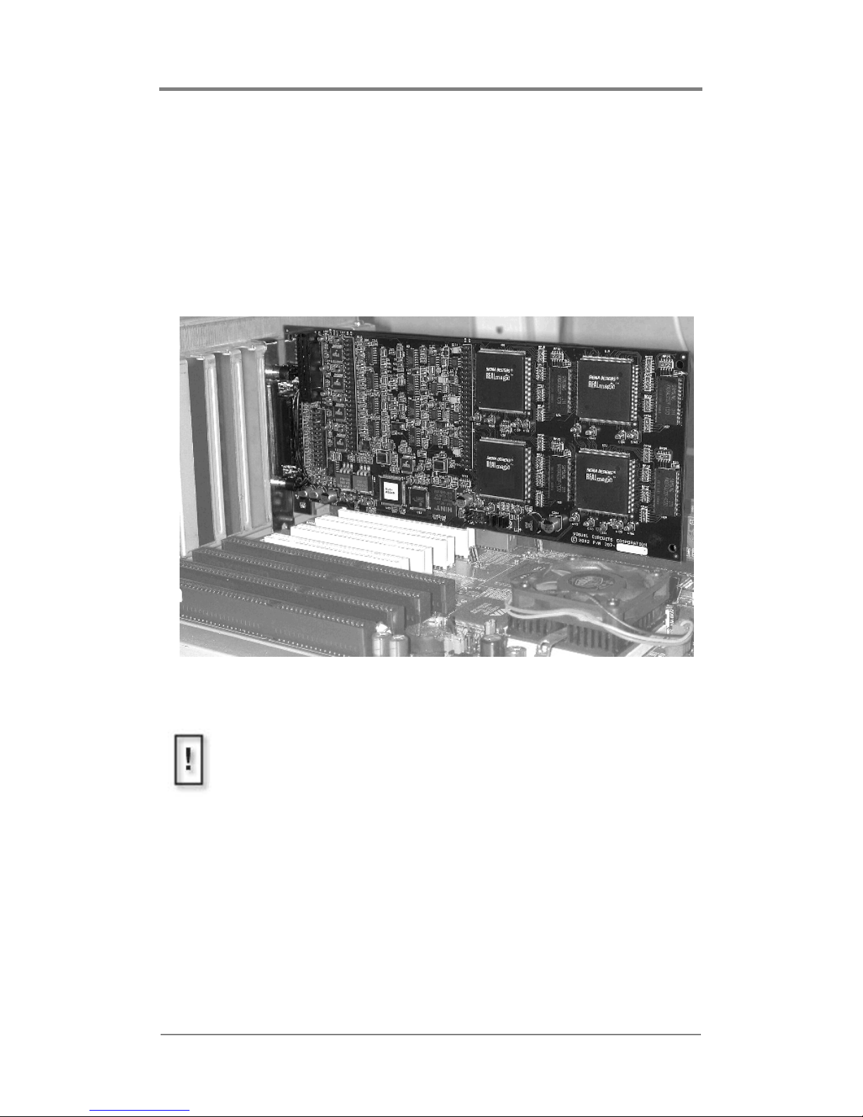
To install the card, carefully slide the board into the selected PCI
or PCIX slot of the main board. Ensure that the bracket is aligned
with the IO opening of the chassis and that the outer edge of the
card rests securely according to the chassis’ design. Consult with
the chassis manufacturer for specific guidelines
Figure 2 Installation of Harmony 4ES Card.
Adjust PCIX Bus Speed for Harmony Cards
Harmony cards may be installed in either PCI or PCIX slots.
However, with PCIX it is necessary to set the PCIX bus speed to
33 MHz to match the Harmony’s onboard clock.
Page 15
Installation Guide
7
Cable Installation (A/V Breakout)
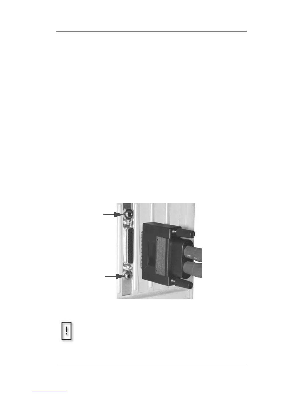
1. Back the set-screws off fully before attaching the cable. Do not
use the attaching screws to “pull” the cable onto the female DSub connector of the board.
2. Orient the D-Sub on the cable properly and apply slight even
pressure while connecting the D-Subs.
3. Secure the Universal Cable in place with the two screws.
4. Attach the patch cables to the Universal Cable as per the
installation.
5. If required, connect the Y-adapter audio cables, (1/8 inch/3.5
mm stereo phone plug to two RCA plugs), from the Harmony
card’s digital audio output jacks to the proper inputs on an
external audio receiver/decoder. Note that the audio output jack
labeled “CH1/2” is designated for channels 1 & 2 and the
second audio output jack labeled “CH3/4” is designated for
channels 3 & 4.
Figure 3 Cable Installation
Ch 1 - 2
Ch3 - 4
Apply Strain Relief When Attaching Patch Cables
The set-screws will easily support the Universal Cable strain, but
will not take into account the weight and strain of any connected
cables.
Page 16
Installation Guide
8
Driver Installation for
Windows 2000/NT 4.0 and
Windows 2003/XP
Table 1: Installation Instructions
Because the installation wizards for all operating systems are
similar, the following installation instructions use the Windows
2000 Installation Wizard for the example.
There are two parts to the installation process:
❏ Installation of Hardware (Part 1, on the following page)
❏ Running the Setup.exe application (Part 2, on page 16)
The sequence of these steps varies depending on the operating
system. Refer to
Table 1 for the correct sequence to use.
OS Installation Sequence
2000 Part 1 Part 2
2003 Part 2 Part 1
NT 4.0 Part 2
XP Part 2 Part 1
Page 17
Installation Guide
9
Part 1: Installation Instructions (Hardware)
To complete this installation, it is necessary to point the system to
the driver installation disc when prompted by Windows.
The harmony.inf file (included on the driver installation disc)
should be installed for each of the video channels.
Installation and use with Windows 2000, requires
Windows 2000 Service Pack 2 or higher.
Uninstall Earlier Versions of Visual Circuits Cards
If you have previously installed a different type of Visual Circuits
decoder card, or a different version for the Harmony decoder
series, it is recommended that you uninstall that driver before
proceeding.
System Identifies Harmony as Multiple Devices
Depending on the Harmony card installed, each channel on the
board appears as a unique device (2 or 4) to the system. During
installation, the Windows to installation wizard prompts for a
driver for each individual video channel.
Page 18
Installation Guide
10
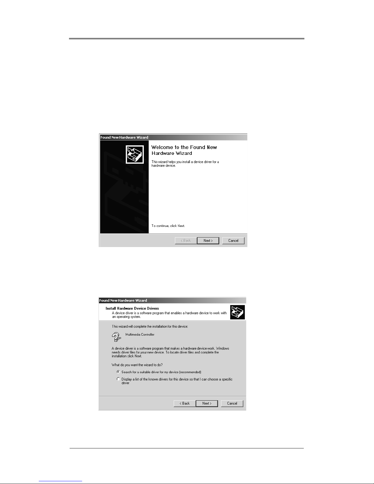
1. Install the decoder card(s) according to the board’s user
manual.
a. Power up the computer and log in to Windows.
b. The Hardware Manager recognizes that new hardware is in
the system and a message box appears stating that Windows
has found new hardware.
c. Click Next to continue.
Figure 4 Welcome to Found New Hardware Wizard Screen
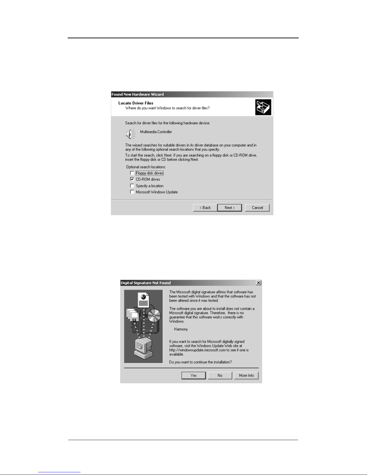
2. Select the first option, Search for a suitable driver for my device,
and click
Next.
Figure 5 Search For Suitable Driver For My Device Screen
Page 19
Installation Guide
11
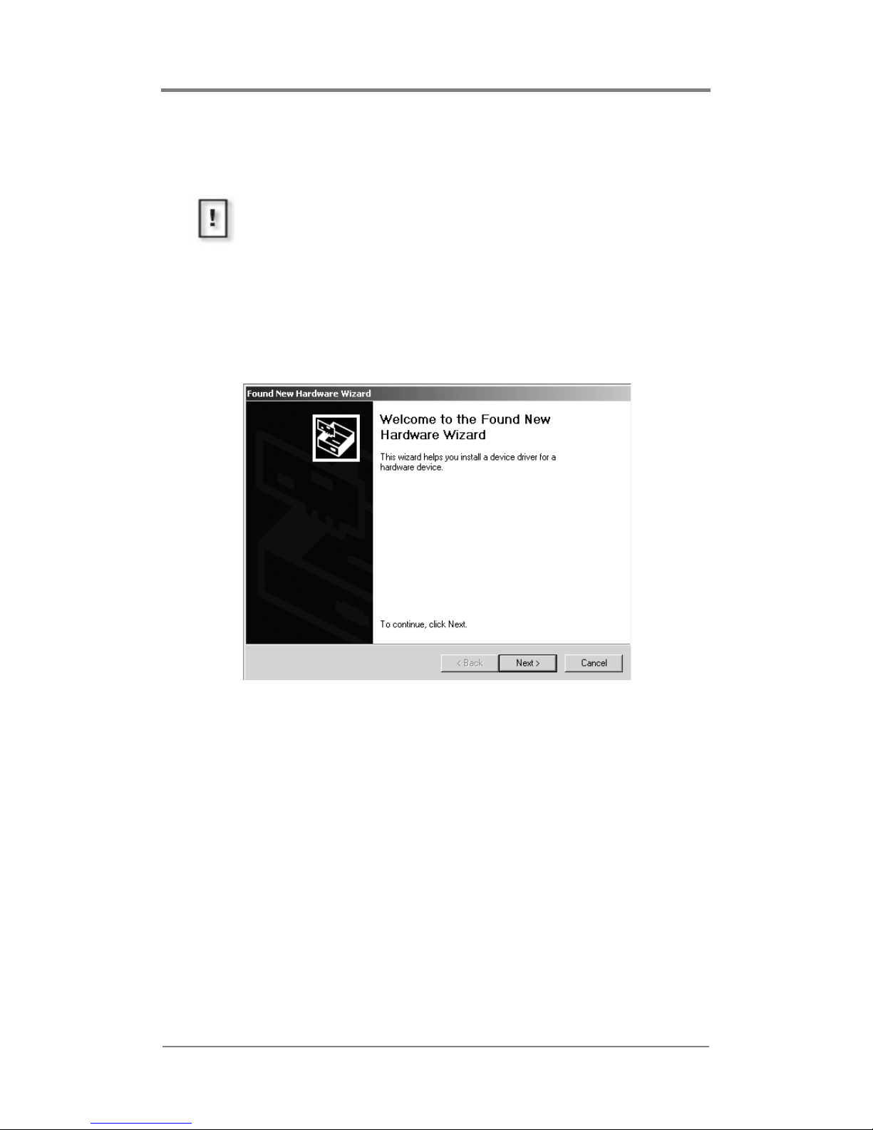
3. When Windows asks for the location of the driver file for this
device, select the location of the supplied driver disc and click
Next.
Figure 6 Search For Driver Locations Screen
4. A dialog box appears, stating that this device does not have a
digital signature and asks if the installation should continue:
click
Yes.
Figure 7 Digital Signature Not Found Screen
Page 20
Installation Guide
12
5. Once Windows has installed the driver for the channel, select
Finish.
6. The Welcome to Found New Hardware Wizard Screen reappears
indicating that more new hardware has been found: click the
Next button to continue.
Figure 8 Welcome to Found New Hardware Wizard Screen
Do Not Reboot System At This Time
If at this time, the system asks if it should reboot, click NO.
Continue to the next step and install the other channels and
cards.
Page 21
Installation Guide
13
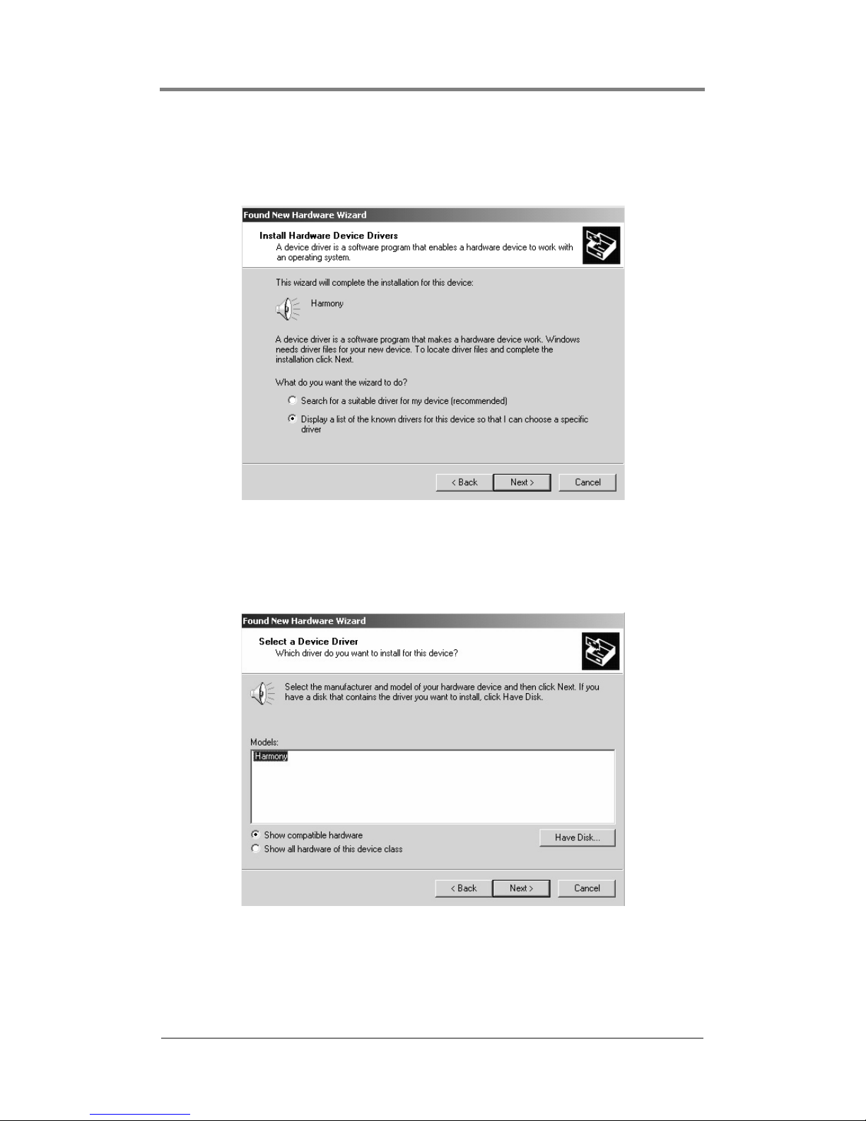
7. Because a Harmony driver is now installed on the system,
select the second option,
Display a list of the known drivers ... ,
and then click
Next.
Figure 9 Display List of Known Drivers Screen
8. The Harmony driver is now in the list and Hardware Wizard
displays it under Models. Click
Next to continue.
Figure 10 Select a Device Driver Screen
Page 22
Installation Guide
14
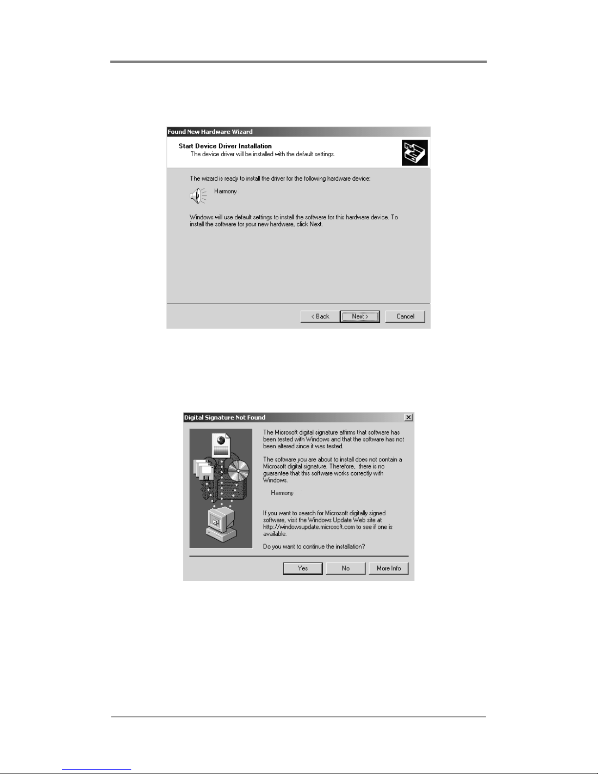
9. The wizard is ready to install the device driver. Click Next to
start the installation.
Figure 11 Start Device Driver Installation Screen
10. A dialog box appears and states that the device does not have a
digital signature and asks if the installation should continue:
click
Yes.
Figure 12 Digital Signature Not Found Screen
Page 23
Installation Guide
15
11. Again, once Windows has installed the driver for the channel,
select
Finish.
12. Determine if more drivers need to be installed.
❏ If the Welcome to Found New Hardware Wizard screen
appears again, then return to Step 6 and continue installing
the additional channel(s) and/or cards.
❏ If the Welcome to Found New Hardware Wizard screen does
not appear again, then Part 1 of the Installation Instructions
is completed.
Part 2: Installation Instructions
(Run SetUp.exe)
1. Run the file SETUP.EXE from the harmony installation disc.
2. In the setup program setup.exe, there are two installation
options to chose from:
❏ Full Driver Install
Choose this option to install the driver and all software.
During this installation, it is necessary to provide
information to configure the driver. The current parameter
settings are overwritten.
❏ Update Only
This option only appears if a previous Harmony driver is
cu rr ent ly i nst al led on t he sys tem .
Choose this option to copy the new drivers and software
onto the system, but leave the current driver settings
unchanged.
3. Choose the directory where the application software should be
installed.
Do Not Reboot System At This Time
If at this time, the system asks if it should reboot, click NO.
Continue to the next step and install the other channels and
cards.
Page 24

Installation Guide
16
4. Choose the shortcut folder name to use.
5. Select Finish and Reboot the system.
Start Menu Icons
Once the system reboots, locate the following icons in the Visual
Circuits group in the Start menu. The manuals require Acrobat
Reader, 4.0 or higher.
❏ Harmony Driver User Manual
Supplies detailed information on the driver parameters and
hardware.
❏ Harmony Encoding Guidelines User Manual
Provides information on how to encode MPEG-2 files for
use with Visual Circuits decoder products.
❏ Harmony SDK User Manual
Contains information about writing programs that use the
driver.
❏ Harmony Vidserve
A player program for testing MPEG files and all of the
Harmony board’s functionality.
❏ Harmony VccReg Parameter Editor
An utility program for changing driver parameters.
Do not use this program unless familiar with the driver
settings.
❏ Uninstall MPEG-2 Drivers
An Uninstall utility for all Visual Circuits driver and
application software.
Additional Files
In addition, the following files are also copied to the installation
directory selected during the install.
Release.doc:
Release notes on the changes in this driver version: Word
document.
Page 25

Installation Guide
17
Sdk\Vidserve.zip:
A Pkzipped file containing the Software Development Kit for the
driver. This consists of the C source code to the Vidserve player
program and all files needed to build it.
Sdk\vb_api.zip:
A Pkzipped file containing all files needed to create Visual Basic
programs that use the driver. Contains source code to a simple
sample program.
Page 26
Installation Guide
18
Starting Playback
Now that Harmony card is installed:
1. Verify that all software applications are closed.
2. Run Harmony Vidserve, the playback application located
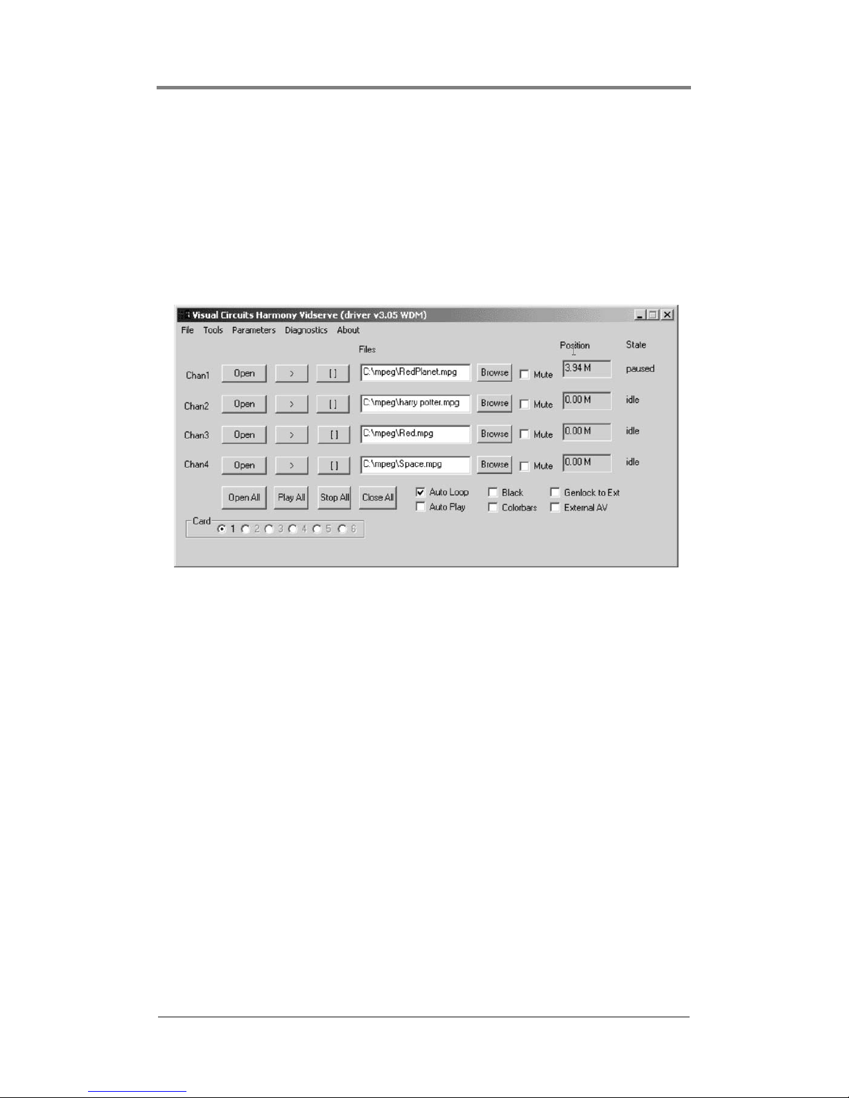
under Visual Circuits’ programs .
Figure 13 Harmony Vidserve Playback Application Main
Window
3. Browse for the MPEG file desired and open it.
4. Click Load and wait for the position counter to stop moving.
Then click Play.
Additional information about the Harmony Vidserve main window
controls are listed in the following table.
Page 27
Installation Guide
19
Control
Description
Open Opens (loads) the MPEG file selected.
> Plays or resumes play of a stopped file which has been
opened (loaded).
[ ] Stops a playing channel.
File Displays the file and full path of the file to be played. You
may type the file path or use Browse (see below). For
multiple drive servers, be sure to map the file path for
each card/channel to the correct drive based on the
server specifications.
Browse Locates the file path of the desired MPEG and opens the
file.
Mute Toggles audio on/off for each channel.
Position Shows the current file read byte position. (Slightly ahead
of actual video playback.)
Open All Issues an open command to all channels on all boards.
(After this command is selected wait until all position
counters stop. Now all indicate that the buffers will be
loaded. Load time is determined by buffer sizes and
system performance.)
Play All Issues a play command to all channels on all boards.
Stop All Issues a stop command to all channels on all boards.
Close All Issues a file close command to all channels on all
boards.
Auto Loop Files continue to playback smoothly and repeatedly.
Auto Play A play command will automatically be issued after Open.
(Do not select this for normal use.)
Black Toggles black/video on all channels.
Colorbars Toggles color bars on all channels.
Genlock to
External AV
Genlocks all channels on currently selected card to
external A/V source.
External AV All channels on currently selected card will output the
external A/V source.
Card Selects desired card. Data supplied pertains to this board
only.
Table 2: Harmony Vidserve Controls
Page 28
Installation Guide
20
Obtaining File Information
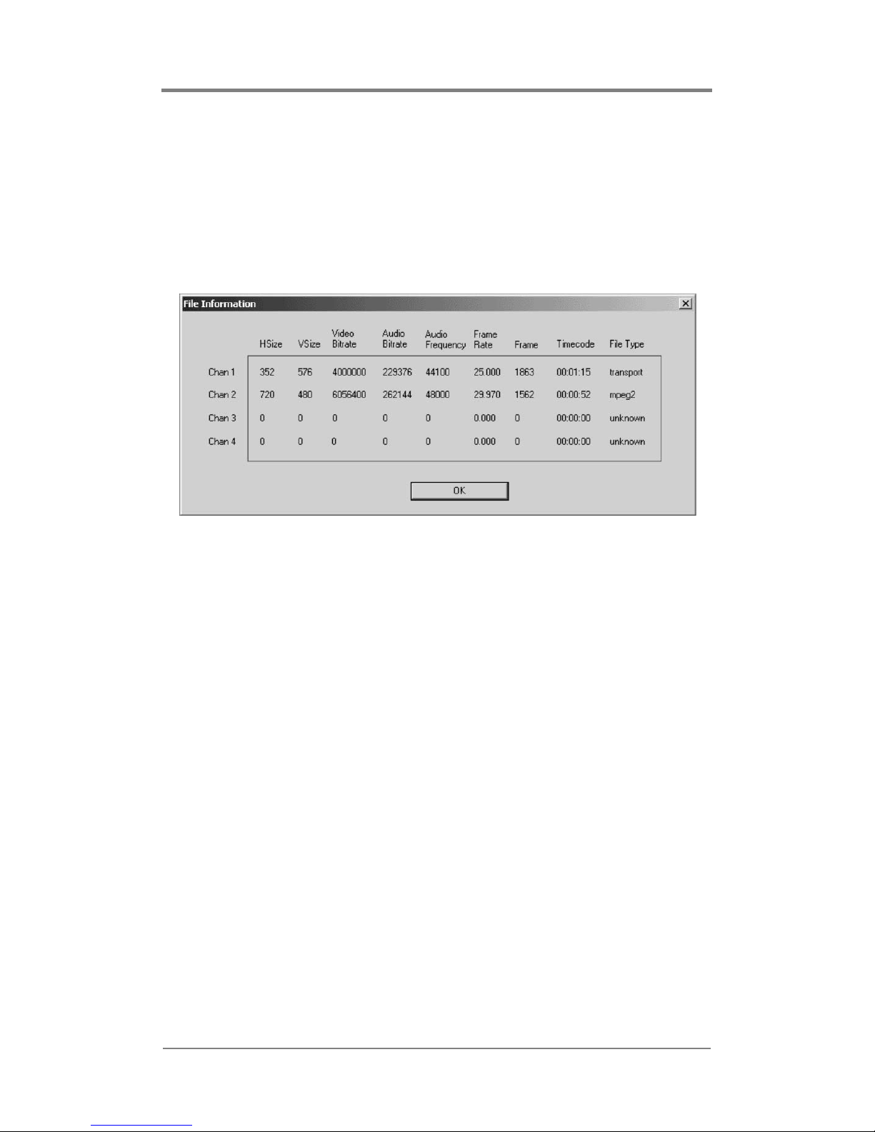
The Harmony supplies extensive information about the MPEG
files the files currently playing through the File Information
feature. To access this information, select
Diagnostics from the
main menu and then
File Information from the drop down menu.
Figure 14 Harmony Vidserve Playback Application File
Information Window
Within the File Information window, the following information is
available:
❏ Horizontal Size
❏ Ve rti c a l S ize
❏ Video Bitrate
❏ Audio Bitrate
❏ Audio Frequency
❏ Frame Rate
❏ Frame
❏ Timecode
❏ File Type
To obtain more diagnostic-related information about the software
driver, select “Driver Diagnostics” from the “Diagnostics” drop
down menu.
Page 29
Installation Guide
21
Using On Screen Displays
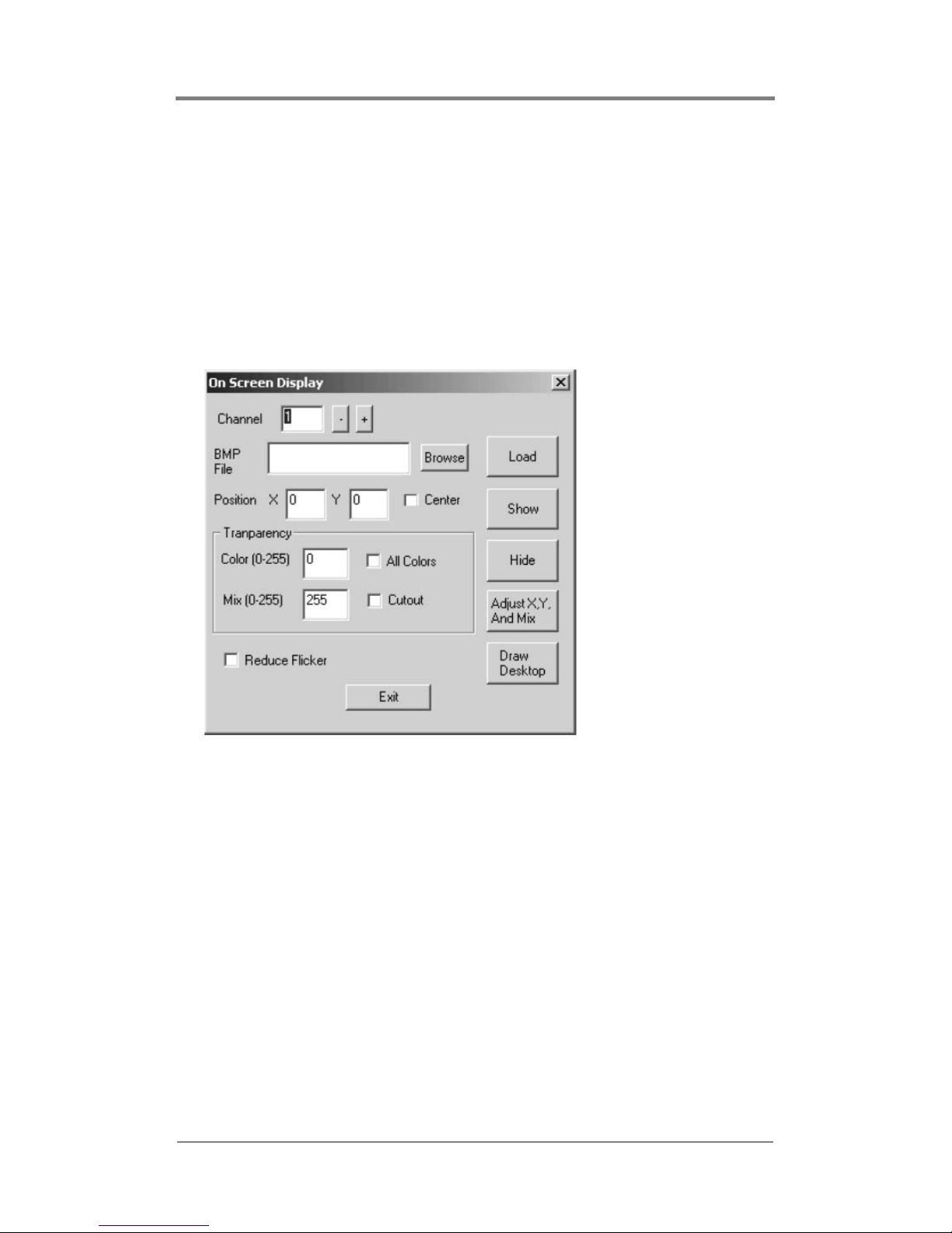
The On Screen Display feature provides a ability to position an
image, such as a company logo or graphic, on top of the video
playback.
To access the On Screen Display window, first select the Tools
drop down menu.
Figure 15 Harmony Vidserve Playback Application On Screen
Display Window
The On Screen Display offers the capability of adjusting many of
the properties of the on screen display, such as:
❏ Channel number where the display is to appear,
❏ Position using X and Y coordinates or the Center check
box,
❏ Transparency level of overlay image,
❏ Reduce Flicker reduces the flicker sometimes seen with
sharp lines.
❏ Fade to Black provides capability for fadeouts.
Page 30
Installation Guide
22
Testing Genlock and External
Audio/Video
The external audio/video feature allows the insertion of live
external audio and/or video playback, such as a satellite or cable
television broadcast, into the presentation mix.
To test external audio/video and genlock, complete the following:
1. Connect an external audio/video source to the Harmony 4ES
card (see
Pinouts on page 54 for details). The Harmony 4ES
card accepts a single composite external audio/video input and
can distribute the external audio/video to all of the four channel
outputs. (To select external A/V on a channel-by-channel basis,
use the Harmony SDK interface).
2. Check the “Genlock” check box to enable genlock. This will
genlock all of the channels on the currently selected card to the
external A/V source.
3. If you check the “External A/V” button, all four channels on
the currently selected card will output the external audio/video
source.
For troubleshooting information, see Troubleshooting Tips on
page 41.
Genlock Must Remain Enabled for External Audio/Video
Do not uncheck the Genlock feature check box while playing
back external audio/video. Genlock must be enabled for the
external audio/video feature to work properly.
External AV Output Types
Although the input for external audio/video is composite, it can
output to a variety of output types; including composite, s-video,
RGB and component.
Page 31
23
EDITING DRIVER SETTINGS
Driver Editing Utility: Harmony
VccReg.exe
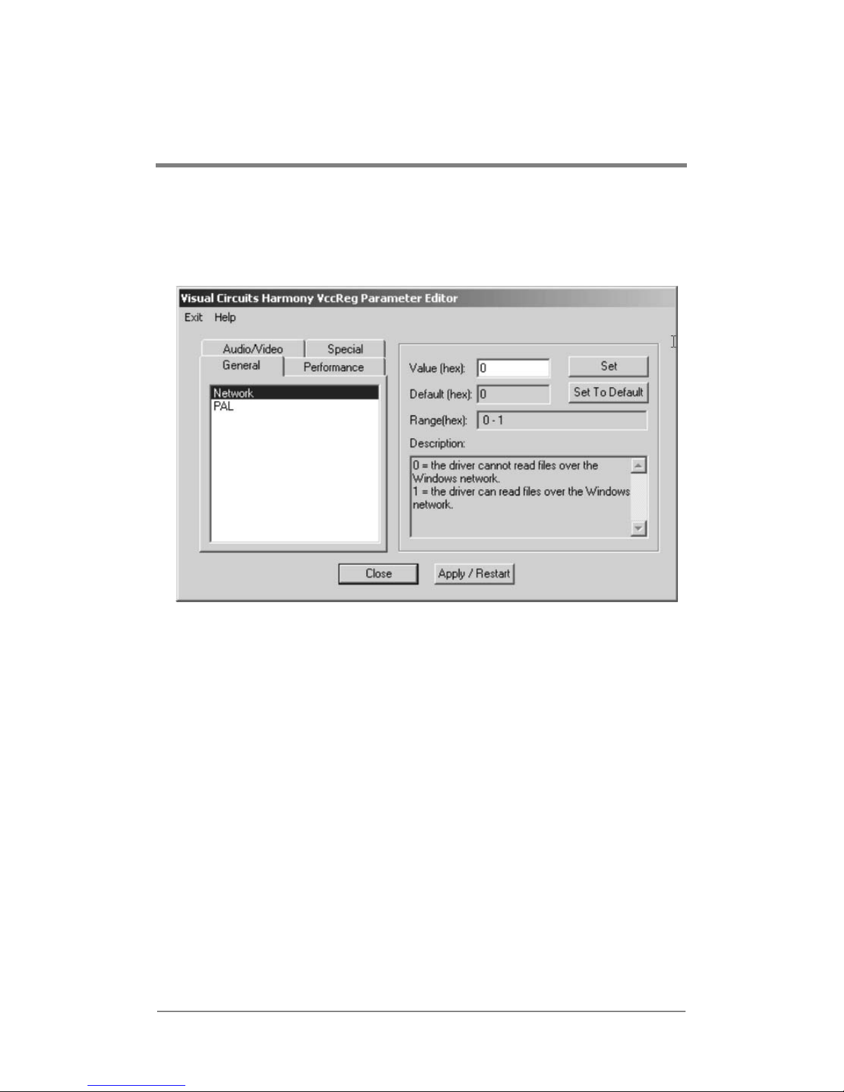
Figure 16 Harmony VCCReg Parameter Editor
Common Driver Parameters
Harmony VccReg.exe is a driver editing utility designed
specifically for editing the VCCmpeg2 driver settings.
There are four tabs containing different parameters, descriptions of
these parameters, and driver default settings. The four tabs in
Harmony VccReg.exe are General, Performance, Audio/Video and
Special and are located on the left side of the window. The right
side of the window contains the Value, Default, Range and
Description fields.
Page 32
Editing Driver Settings
24
To change a parameter, enter the appropriate information in the
Value field and click the set button
. If you want to
restore the default value, click the set to default button
.
General
Network
0 = The driver cannot read files over the Windows
NT network.
1 = The driver can read files over the
Windows NT network.
Default = 0
Range = 0-1
PAL
0 = NTSC (default)
1 = PAL
Page 33

Editing Driver Settings
25
Performance
BufferSizePerChannel
Amount of RAM allocated for each channel.
A larger buffer supports larger minimum
file reads which reduces hard drive
seeking.
Default = 400000 hex, high performance playback
(optimal)
recommended.
Range = 100000-800000 hex
MaxDisks
This parameter sets the number of disk read
threads.
The channels are divided into maxdisks
groups, and
each group must play off a different
physical drive.
Default = 1, Single MPEG storage drive
(normal operation).
Range = 1-4
See on page 30 for more information.
MaxFileRead
Set the largest file read the driver will
perform.
It must be larger than minfileread.
Setting maxfileread to a half of
BufferSizePerChannel is recommended.
Default = 200000 hex
Range = Fits evenly in BufferSizePerChannel
Page 34

Editing Driver Settings
26
MinFileRead
Sets the smallest file read size the driver will
manage.
The larger the minfileread is, the less HD
seeking there will be.
Setting minfileread to a quarter of
BufferSizePerChannel (half MaxFileRead) is
recommended.
Default = 100000 hex
Range = Fits evenly in BufferSizePerChannel
Page 35
Editing Driver Settings
27
NoCache
0 = Normal NT file system caching is used.
1 = The cache is not grown when files are
played.
Default = 0
Range = 0-1
NonPagedPoolSize
Reserves a block of memory for decoding.
When changing NonPagedPoolSize, the system
will require rebooting for Windows NT to
allocate memory.
NonPagedPoolSize = BuffersizePerChannel x 4 x
number of cards + 800000 hex
e.g. 1 card: 1800000 hex
2 cards: 2800000 hex
This parameter will be set correctly by the
installer for the number of cards you
chose.
Default = 0, NT/2000 automatically assigns.
Usually too low if there are multiple
boards or a large buffer.
NoReadBuff
0 = Normal file caching.
1 = Disables all hard drive caching.
REQUIRED TO BE 1 FOR WINDOWS NT SERVICE
PACK 4 OR HIGHER.
Default = 1
Range = 0-1
NoREadBuffer Preferred Method for Dissolving File
Caching
NoReadBuff provides a preferable method to dissolve file
caching and should be used instead of NoCache.
See below.
Page 36

Editing Driver Settings
28
Audio/Video
DisableSync
0 = Enables audio/video synchronization.
1 = Disables audio/video synchronization.
Default = 0
Range = 0-1
VideoTypes
0 = All channels output S-Video/Composite.
1 = All channels output Component.
2 = All channels output RGB (sync on
green).
Default = 0
Range = 0-2
Page 37
Editing Driver Settings
29
Special
InitOnOpen
0 = Files are loaded smoothly without a
disturbance to the video output.
1 = The decoder chip is reinitialized whenever a
new file is loaded. Output is black after
load until it plays.
Default = 0
Range = 0-1
dontuseints
0 = Normal interrupt driven playback.
1 = Interrupts not used. (Improves
compatibility).
Default = 0
Range = 0-1
LateLoadNext
Sets the handling of mpgLoadNext calls that
arrive after playback has stopped.
0 = Late mpgLoadNext calls will be ignored.
1 = Playback will always resume.
Default = 1
Range = 0-1
Use mpgBlack for Black Screen, Not InitOnOpen
If a black screen is required, use the call mpgBlack rather than
this parameter.
InitOnOpen = 1 is a useful diagnostic tool, but may cause
anomalies at some transitions.
Page 38

Editing Driver Settings
30
MaxCards
The number of channels to initialize can be fewer
than the actual number of channels in the
bus, for testing purposes. (There are four
channels on each card).
Default = 8
Range = 1-8
Multiapp
0 = Only one application can link to 4reelapi.dll
at a time.
1 = Multiple applications can access the
driver, but callbacks are disabled.
Default = 0
Range = 0-1
Page 39

31
MULTI-CARD SERVERS
Multi-Threading
and Drive Mapping
Depending on hard drive speed and bitrate, proper drive mapping
can be crucial for MPEG playback performance. This involves
configuring the Harmony driver so that it reads from multiple
physical hard drives simultaneously. In a system with two hard
drives storing MPEG content, maximum performance occurs when
data is read from both drives at the same time.
MaxDisks drive parameter
Use the MaxDisks driver parameter to specify the number of
playback storage hard drives used in a system. The driver divides
the available playback channels into MaxDisks groups with each
group performing concurrent reads; in software terms, each group
has a separate thread of execution. Therefore, it is important to
configure the application so that each group of channels should
read files from a physical hard drive that is not used by another
group.
Single drive systems
The MaxDisks default value 1, dictates that reads from all the hard
drives are sequential, i.e. only one read of MPEG data occurs at a
time. This is acceptable when using a single content drive.
However reading from multiple content drives, a read from one
drive must complete before a read on another drive can start. This
does not take advantage of the performance potential of a multidrive system.
Page 40

Multi-Card Servers
32
Multi-drive systems
The use of multiple content drives in a system is useful when it is
not possible to store all MPEG content on a single drive or there
are multiple channels playing different content. Each channel
group has its own drive(s) for content storage.
For simplified mapping, divide the number of channels evenly and
sequentially across multiple boards.
Page 41
33
ENCODING PARAMETERS
Listed below are requirements and recommendations for both
Standard and High Definition encoding, that provide criteria to
create MPEG files compatible with the Harmony playback system.
1. Files must be one of the following types:
a. program stream MPEG2 or transport stream MPEG2
b. system stream MPEG1 of audio/video
c. elementary stream MPEG2
d. MPEG1 of video only
e. audio only
2. Use 4:2:0 encoding.
3. With MPEG-2, both audio and video fields must be encoded.
This is the normal default.
4. Audio only (Dolby Digital or MPEG Layer 2) files cannot be
mixed with files containing videos (MPEG, MPEG2 program
stream, video only).
5. Total output across all channels can not exceed 40 Mbps.
6. The presentation time stamp (PTS) values contained in the
audio and video streams in a file must be continuous and
increasing.
In particular, the PTS values should not reset to 0 at any point
in the file. The time between the first and last time stamps in a
file should reflect the actual duration of that file.
7. Files should be no less than 4 MB in size. If there are files are
smaller than 4 MB, use an editor to combine them into a larger
file that is at least 4 MB in size.
Do Not Use 4:2:2 encoding.
Page 42
Encoding Parameters
34
Encoding Recommendations
1. Resolution:
• 704 x 480 or 720 x 480 in NTSC
• 704 x 576 or 720 x 576 in PAL
2. Closed GOP (Group of Pictures) with an “I-frame” every 15
frames is recommended.
3. The recommended audio bit rate is 384 Kbps and a sampling
rate of 48 kHz.
Before encoding an entire project, play back the test files
using the original source tapes to confirm audio level. This
allows for calibration of the encoding system by obtaining a
standard audio level.
4. Program stream files should have one end code (00 00 01 b9)
at the very end of the file. While the Harmony can handle files
without end codes, it is a good encoding practice to include
one.
5. The bit rate can affect the size of files used and the ability to
transfer them. The following are the recommended bit rates for
various types of video content:
Bit Rate Video Content
4 Mbps Good quality with low motion
6 Mbps Good quality with typical motion
Recommended
8 Mbps Good quality with high motion
10 Mbps Demanding content
Table 3 Bit Rate Encoding Recommendations
Page 43
Encoding Parameters
35
6. Although the Harmony can transcode NTSC and PAL, it is
recommended to encode to the video standard (NTSC or PAL)
that the Harmony is set to display.
7. When encoding files, annotate and store notes on the audio
levels of both the source tape and input settings of the encoder.
This permits verifying the audio levels of later encoding
sessions.
8. MPEG files are constructed from i.e. multiplexed audio and
video streams. If possible, the length of the video and audio
stream segments within the MPEG files should be identical.
Ending the audio segment at
a .5 second interval (i.e., at an “I-frame”) ensures identical
stream lengths and results in smooth and seamless looping
playback.
9. It is recommended that SMPTE tracks should be encoded as
hot, at approximately +6db.
This adjustment compensates for some SMPTE information
that may be lost during compression. Sample testing should be
done with all SMPTE tracks because not all encoders respond
in the same way.
10. For reference and calibration, encode into the MPEG files the
standard color bars and audio test tones along with the content
or source files. These encoded display test and audio tuning
files should be separate files, not headers or footers of the
presentation.
Even when encoding is done at the same production facility,
variances between sessions may occur and once MPEGs are
encoded, the audio level of a file cannot be changed unless
the file is re-encoded or a new audio track is mixed.
Thus, it is desirable to maintain a baseline audio level across
all files of a presentation whether at single or multiple
locations. If no encoding notes or data are available from
previously encoded files, compare the files. When possible,
measure the audio levels of the source tapes and of the
encoded files. At a minimum, listen to and compare the files.
Page 44

Encoding Parameters
36
11. To play back still images or computer-based graphics,
hardware-based encoding systems are preferred. However, if a
software encoder is needed, we recommend encoders such as
DVMPEG (www.darvision.com).
Page 45
37
CROSS-CHANNEL
SYNCHRONIZATION
The Harmony 2ES and 4ES provide the capability of cross-channel
synchronization, i.e. the ability to coordinate the starting and
stopping of video playback on multiple channels.
The Harmony supports the following cross-channel
synchronization features:
❏ Multiple synchronization groups
The Harmony can support multiple synchronization groups.
❏ Synchronized files must be the same length in frames.
To insure that synchronized files start and stop precisely,
they must have the same run time, i.e. number of frames.
❏ Channel 1 audio output to all synchronized channels in
group.
The audio track on channel 1 is used as the master for all
audio channels in the group. If any of the slave channels
have audio tracks, they are disabled and not output.
File Length for Looping Playlists
Likewise, when synchronizing looping playlists, the
files playing simultaneously must have the same
number of frames to insure that they and the playlists
stay synchronized.
Page 46

Cross-Channel Synchronization
38
Cross-channel Sync Commands
The Harmony supports specific serial commands to implement
cross-channel synchronization.
❏ mpgSyncChannel
Use to create a synchronized group of channels.
❏ mpgUnSyncChannels
Use to cancel a synchronization group.
❏ mpgPlaySyncChannels
Use to start all channels in a group.
❏ mpgStopSyncChannels
Use to stop all channels in a group.
For a complete description of these and other serial commands
supported by the Harmony, refer to the Harmony SDK.
mpgPlay, mpgPlayAll, mpgStop, mpgStopAll
If all channels are part of the same sync group, then the commands,
mpgPlay, mpgPlayAll, mpgStop and mpgStopAll are
interchangeable with their cross-channel counterparts.
Page 47
39
TROUBLESHOOTING
Overview
Server Setup Check
Prior to any troubleshooting, power down the system and verify
that the card is properly installed in the system’s PCI or PCIX slot.
Test only one card in the system at a time.
1. Confirm that the system has the power connected properly.
2. Confirm that all video and audio cables are connected properly.
Video output is:
❏ compatible with TVs,
❏ compatible with video monitors,
❏ not compatible with standard VGA computer monitors,
3. Select the correct input type for the display. Examples: Video
1, Input 1, S-video, etc. Refer to the display manual for use.
4. Remove all serial cable and network connections from the
system.
Only authorized technicians should perform board
troubleshooting or system repairs. Unauthorized repair
of systems may void warranty.
Page 48
Troubleshooting
40
Getting Started
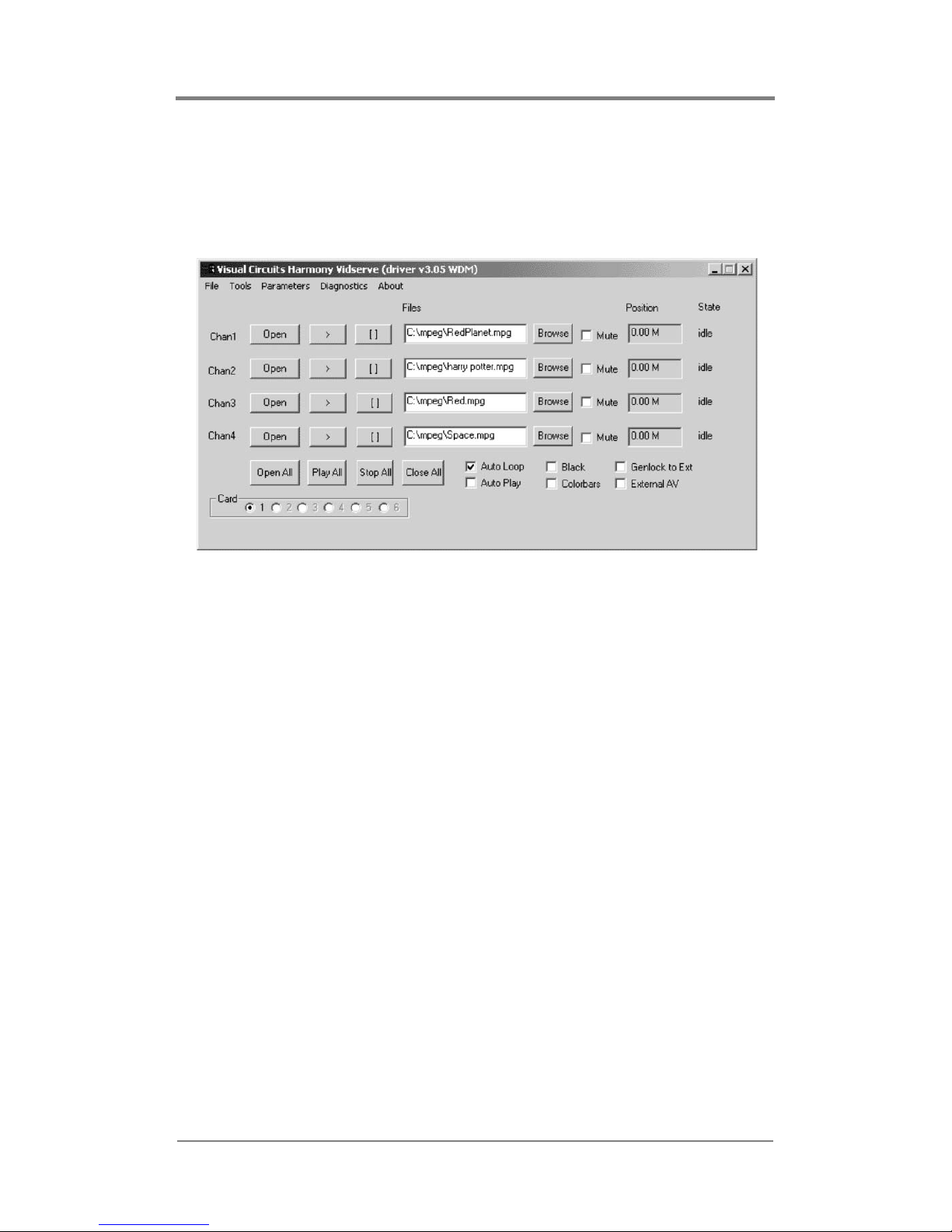
1. Power the server up and open Harmony Vidserve playback
application located under Visual Circuits programs.
Figure 17 Main window of the Harmony Vidserve Playback Application
On the main application window, the radio button selected should
indicate Card 1 found. If it states “Harmony driver not found” see
page 42 for tips on how to fix the error.
2. Be sure the Auto Play and Black check boxes are not selected
on the main window. Using the Browse button, select a file for
channel 1 and click Open. Note the Position window and see
that the counter has stopped increasing. Next click the Open
button for channel 1 and be sure that the position counter resets
completely.
3. Next, click Play for channel 1 and view video and audio
playback.
4. Repeat the process for each individual channel by browsing,
opening and playing files. Be sure to play only one file at a
time.
By performing the above process, you can determine if basic
playback for the board is functioning.
Page 49

Troubleshooting
41
Troubleshooting Tips
BIOS Settings
Ensure that the BIOS settings for Windows servers have the “Non
PnP OS” selected.
Blue screen
❏ If a Blue Screen occurs during Windows startup and
Windows cannot be started, remove all Harmony cards
from the system and reboot.
❏ Try a process of elimination to run the system in a single
minimal system configuration, such as by inserting each
device into the system and rebooting. Usually starting with
the VGA/AGP card, if it is not integrated into the
motherboard.
❏ Try placing the Harmony card in a different PCI or PCIX
slot.
Page 50
Troubleshooting
42
'' Harmony Driver not found!'' when
Harmony Vidserve started
❏ ‘Harmony: Board was not found"
Make sure the board or boards are securely seated in the
PCI bus.
❏ "Harmony: Failed to allocate mem"
Be sure to verify that the BufferSizePerChannel is set
correctly in Harmony VccReg. Verify all memory is
detected by server on start up or by right clicking on My
Computer and reviewing General.
❏ "Harmony: HARDWARE ERROR"
Inspect the decoder board for damage.
Make sure your motherboard has 3 volts available in the
PCI slots.
Remove the board and re-install.
No video or audio output
❏ First, ensure that the cables are plugged in properly and that
the video and audio outputs are plugged in correctly to the
display device. Try testing another channel of the server on
the same display. Try using other cables.
❏ Note that the output of the decoder board will not display on
a PC monitor.
❏ Dolby Digital MPEG files cannot play on the analog Audio
output.
Error Messages Displayed in Windows Event Viewer
The error messages listed below are found in your system’s
Event Viewer.
For Windows NT: Locate Administrative Tools, then open Event
Viewer.
For Windows 2000: Right click on My Computer, then open
Manage, then Event Viewer and finally System.
Page 51
Troubleshooting
43
Stuttering files during Playback
Irregular playback on single and multiple channels can be caused
by a number of conditions:
❏ Cross-channel synchronization requires equal playback
duration of MPEG files.
If a problem occurs during cross-channel synchronized
playback, verify that the file length of matching MPEG files
have equal numbers of frames. The Harmony measures file
length by frames rather than playback time. In addition
check that the bitrate for all channels is equal.
❏ The bit rate of the MPEG files being played exceed the
system capabilities: The Visual Circuit MPEG decoder
boards and digital servers all have a maximum sustained bit
rate that can be delivered. Refer to the system board and
specifications for information. Please consult your Visual
Circuits representative prior to encoding or designing your
installation if there are any questions.
❏ Incorrect channel to drive mapping in multi-card systems
with multiple content drives. For more information see
Multi-Card Servers on page 31.
Do Not Mix Harmony 2ES/4ES with Earlier Harmony or
ReelTime Boards
Page 52
Troubleshooting
44
"Latent Images" or "Flashing" during
playback
❏ Incorrect source timecode provided or improperly closed
encoding session. If the incorrect timecode for a file on tape
is given, it is possible to encode a frame or two of trailer or
header information from the tape. Often this “extra” frame
may be seen only briefly and may appear as a visual flash
on the screen during looping playback. Review the original
source material and determine if the timecode are correct
for the tape, or if the encoding session was actually started
and closed on the correct frames.
SMPTE time codes are not recognized
properly
❏ Some SMPTE tracks lose information during compression
and may not “trigger” events as required. Testing is
essential to account for variances in encoders and SMPTE
devices involved.
Video blocks or stutters when starting
playback
❏ Be sure buffers are fully loaded before calling a playback
command. Usually following the initial buffer load, a delay
is required.
Timecode
Timecode is the current playback position, in units of
90000 per second.
Page 53

Troubleshooting
45
Overall block or distorted playback
❏ Try playing another file or a Visual Circuits demo file to see
if the problem is specific to a file. If so, the data may be
corrupt.
❏ Make sure that NTSC is not being played to PAL or vice-
versa (the vertical resolution is 576 in PAL and 480 in
NTSC). Set the PAL setting in Harmony VCC Reg to agree
with the type of video monitors you are using.
❏ Possible damage or faulty channel or decoder card. Use test
files and try other channels to verify. Always try one file
and one channel first as a base line for troubleshooting.
❏ Verify ATA 133 to ATA 33 compatible components and
drivers. A different IDE bus driver may be required for
proper system performance.
Problems using the API
❏ Make sure you are using the standard C calling convention.
Refer to the SDK documentation for questions.
Mouse lags and overall poor system
performance
❏ Verify ATA 133 to ATA 33 compatible components and
drivers. A different IDE bus driver may be required for
proper system performance.
MPEG will not play on mapped network drive
❏ This will not work unless you set network = 1, see Network
on page 24 for details.
Page 54

Troubleshooting
46
Harmony Vidserve does not work at all
❏ Only one program can access the driver at a time. Close all
programs using the Harmony driver and run Harmony
Vidserve again.
All channels pause when a new file is started
on a channel
❏ Be sure buffers are fully loaded prior to playing. As the
number of channels being used increases, this delay may
need to be increased depending on individual server system
resources. Test with maximum channels playing to
determine the system’s threshold and maximum delay
required.
No audio
❏ Make sure mute button is not checked.
❏ Check cables and test with other audio source.
❏ When a Dolby Digital encoded file is playing, the analog
audio output will be muted.
More than one board will not play or make a
few horizontal lines on the screen
❏ Make sure BIOS is not set to PnP operating system.
❏ Verify number of boards and number of channels using
Harmony VccReg.exe driver editing utility.
PCIX System Hangs with Harmony
❏ Verify that PCIX bus speed has been set to match the
Harmony board clock speed of 33 MHz.
Page 55
47
CONTACTING
FOCUS ENHANCEMENTS
Support for Users
If the Harmony decoder board is experiencing problems, first
consult the Troubleshooting section on
page 39 and the support
information available at www.visualcircuits.com. Then, if more
help is needed, please contact a Visual Circuits Value Added
Reseller or Distributor.
Before calling for support
Before calling for support, collect the following information:
Information needed by Technical Support
Serial Number of Harmony board:
_____________________
Date of Purchase:
_____ / ____ / _____
Name of Seller:
Complete description of problem:
Page 56
Contacting Focus Enhancements
48
Support for VARs and Distributors
Value Added Resellers (VAR) and Distributors of Focus
Enhancement’s Visual Circuits products, can call Focus
Enhancement’s technical support. Calls are handled in the
following manner:
1. A technical support representative records the information
provided by the User: board serial number, date of purchase
and seller, and problem description.
2. Technical Support attempts to resolve problem over the
telephone.
3. If the problem can not be resolved during the initial
conversation, the representative arranges for a follow up call
and provides a reference number to use while tracking work on
the problem.
Contact Information for
VARs and Distributors
The e-mail address for technical support of the Visual Circuits
product line is:
The telephone numbers for technical support of Visual Circuits
products are:
❏ In the United States, 1-800-250-5533
❏ Outside of the United States, 763-571-7588
After Regular Business Hours
If the support call occurs after regular business hours, CST,
and the problem is not immediately resolved, the support
engineer arranges for a call back the following business
day.
Page 57
Contacting Focus Enhancements
49
VARs and Distributors
Returning Materials
to Focus Enhancements
If the problems with the Harmony board can not be corrected over
the telephone, it may be necessary to return the board to Focus
Enhancements, Midwest Headquarters.
All materials shipped back to Focus Enhancements must be
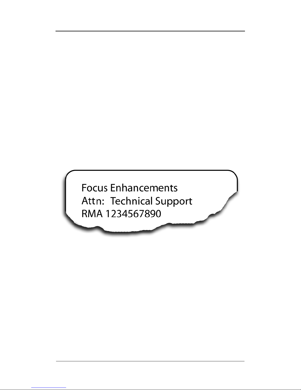
accompanied by a Return Materials Authorization (RMA) number.
Contact Focus Enhancements Technical Support to receive a RMA
number.
Write the RMA number clearly on the shipping label.
Figure 18 RMA Shipping Label
Page 58

Contacting Focus Enhancements
50
Page 59

51
APPENDIX
This Appendix contains:
AV Breakout Cables . . . . . . . . . . . . . . . . . . . . . . . . . . . . 52
Harmony Specifications . . . . . . . . . . . . . . . . . . . . . . . . . 55
Vidcom Serial Command Interface. . . . . . . . . . . . . . . . . 57
Page 60
Appendix
52
AV Breakout Cables
Table 4 Specifications AV BreakOut Cables
For all cables, 75-ohm cable is recommended for all video outputs
and inputs if applicable.
Feature Description
Physical Length = 9.4'' (239mm)
Height = 4.25'' (108mm)
Connectors 25-pin D-Sub (use with universal breakout cable.)
Dual 3.5 mm jacks for digital audio output.
Power All active channels:
• 10.5w Typical (playback to TV)
PCI Voltages
• +3.3V 2.8A (TV)
• +12V 0.09A
• -12V Not used
Audio
Parameters
Sampling rates supported:
• 32khz,
• 44.1 khz,
• 48khz,
• 96 khz
Frequency response:
• 20hz - 22khz +/- .5db
MPEG layer 2 audio, Dolby Digital
• Stereo 16 bit,
• 20 bit,
• 24 bit output,
• Passes Dolby Digital via S/PDIF connector.
Volume, balance software controllable
Volume, balance software controllable
Software controllable mute
Software controllable stereo channel routing (mono, dual
mono, right or left, etc.)
Audio output level: -10dB
Audio output impedance: 10K Ohms/unbalanced
Page 61
Appendix
53
When attaching the leads, solder cup connectors work fine, but
crimp type pins provide more durability and hold up better under
strain. An example of a cable that works well for video is the
Belden series 9221 mini-coaxial cable (www.belden.com), but
other cable manufacturers can also be used.
Audio lines need to be quality audio wire. An example of a
compatible audio cable is the Assmann Electronics AK243-2 3.5
mm stereo to 2 phono plugs cable (www.assmann.com). Note that
two separate audio cables will be required to connect all 4
channels: one cable for channels 1 & 2 and the other for
channels 3 & 4.
Ensure that all leads are properly grounded within the D-Sub and
that proper strain relief is provided to prevent separation of wires
from the pins or connectors. Also ensure that all connectors,
whether BNC, RCA, or other are of high-quality material so as not
to break the 75-ohm impedance of the line.
Purchasing Cables
Focus Enhancements does not stock or sell cables, cable
components or cable building supplies. Please contact an Audio/
Video specialist for assistance
Page 62
Appendix
54
Pinouts
Refer to the following chart for pin-out connections.
Pin No. Harmony
1 GROUND
2 AUDIO L/3
3 COMP 3 / BLUE 3
4 LUMA 3 / GREEN 3
5 AUDIO L/2
6 COMP 2 / BLUE 2
7 LUMA 2 / GREEN 2
8 AUDIO L/1
9 COMP 1 / BLUE 1
10 LUMA 1 / GREEN 1
11 AUDIO L/0
12 COMP 0 / BLUE 0
13 LUMA 0 / GREEN 0
14 NOT USED
15 AUDIO R/3
16 CHROMA 3 / RED 3
17 AUDIO IN R
18 AUDIO R/2
19 CHROMA 2 / RED 2
20 AUDIO IN L
21 AUDIO R/1
22 CHROMA 1 / RED 1
23 VIDEO IN
24 AUDIO R/0
25 CHROMA 0 / RED 0
Table 5 Pin-Out Connections
Page 63
Appendix
55
Specifications
Table 6 Harmony Specifications
Feature Description
Physical Length = 9.4'' (239mm)
Height = 4.25'' (108mm)
Connectors 25-pin D-Sub (use with universal breakout cable.)
Dual 3.5 mm jacks for digital audio output.
Power All active channels:
• 10.5w Typical (playback to TV)
PCI Voltages
• +3.3V 2.8A (TV)
• +12V 0.09A
• -12V Not used
Audio
Parameters
Sampling rates supported:
• 32khz,
• 44.1 khz,
• 48khz,
• 96 khz
Frequency response:
• 20hz - 22khz +/- .5db
MPEG layer 2 audio, Dolby Digital
• Stereo 16 bit,
• 20 bit,
• 24 bit output,
• Passes Dolby Digital via S/PDIF connector.
Volume, balance software controllable
Volume, balance software controllable
Software controllable mute
Software controllable stereo channel routing (mono, dual
mono, right or left, etc.)
Audio output level: -10dB
Audio output impedance: 10K Ohms/unbalanced
Page 64
Appendix
56
Table 6 Harmony Specifications (continued)
Feature Description
Video
Parameters
Output level composite video:
1 volt peak-to-peak when terminated with 75ohms
Output level RGB (RT+):
.7v peak-to-peak when terminated with 75 ohms
Standards: NTSC or PAL software selectable
Encoder:Broadcast quality digital video encoder with post
filtering
Resolution:CCIR 601 720x480 NTSC or 704 x 576 PAL
Driver supports automatic selection of SIF format for
MPEG1
Supported
Standards
ISO 11172 (MPEG-1)
ISO 13818 (MPEG-2)
Maximum bitrate:
• Single card server: Individual channel can play up to
15mbps (mbits/second). Maximum total bit rate to
card is 60mbps.
• Multi-card server (up to four cards): combined bit
rate not to exceed 150mbps.
Bus Interface • Conforms to PCI-bus electrical specifications 2.1.
• Operates in bus master mode.
• Can use 3.3v if available on bus.
Environment
Ambient temperature:
• Operating: 0 deg C to 40 deg C
• Non-operating: -40 deg C to 60 deg C
Minimum
System
Requirements
Minimum processor:
• Intel or AMD-based 600MHz/equivalent.
• 1 GHz or higher recommended.
Minimum system memory:
• 256 MB PC-100 (PC-133 recommended.
Hard disk: Ultra ATA/66 or higher.
Audio receiver:
• Dolby Digital audio receiver/decoder and speakers
required for surround sound.
Page 65
Appendix
57
Vidcom Serial Command Interface
The Visual Circuits Vidcom application provides a serial command
interface for editing and sending commands via a direct connection
to the server.
Connecting directly to the Server
Use a null modem cable (RS232, female DB-9 to female DB-9) to
connect to the server serial COM port from a laptop or PC.
Vidcom Interface
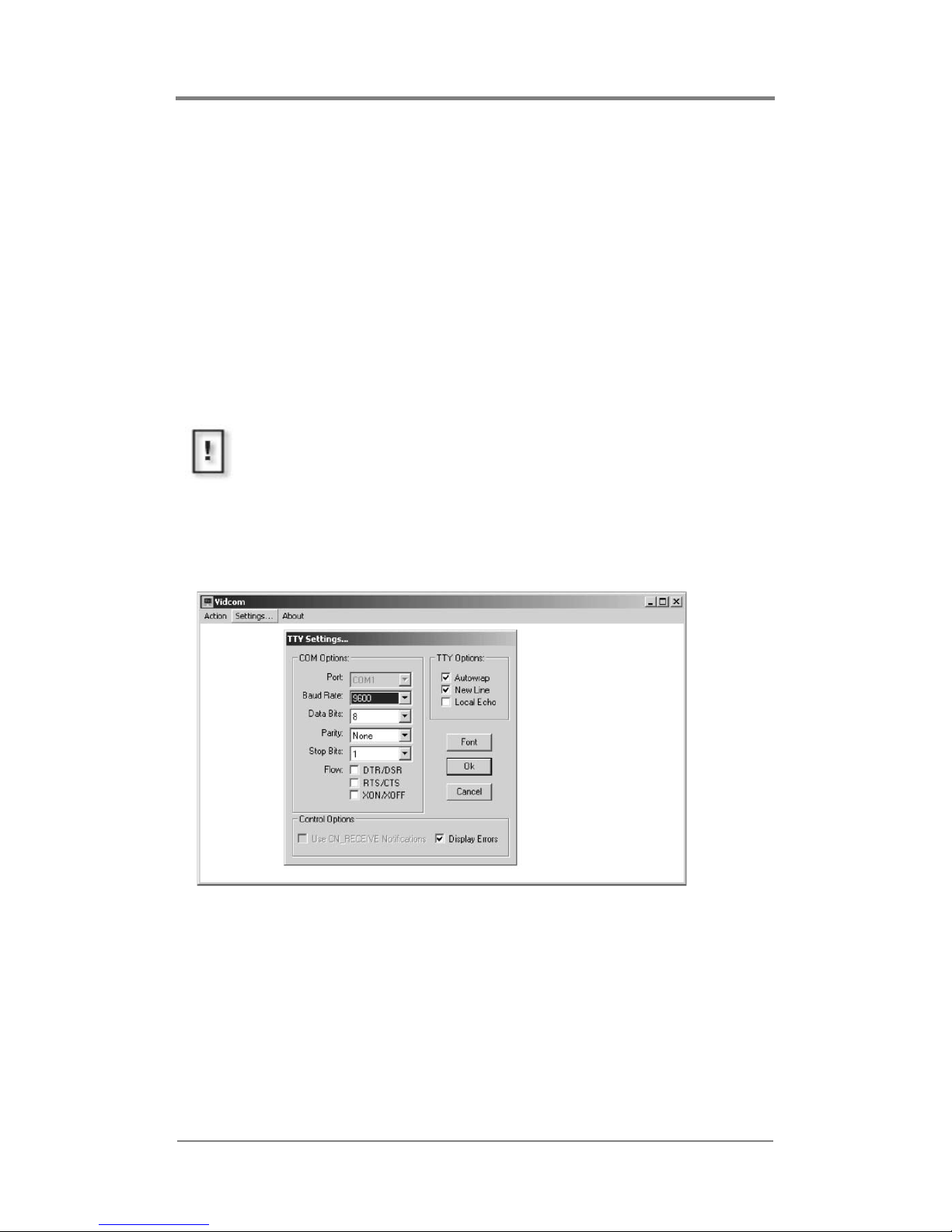
Figure 19. Vidcom Main Screen with TTY Settings Displayed
Use Vidcom’s simple command interface to manually enter
commands channel-by-channel.
Power Down Computer and Server Before Cabling
To protect both the computer and server, verify that both are
powered down before attaching the null modem cable.
Page 66
Appendix
58
Vidcom Supported Serial Commands
Table 7 Serial Commands Supported by Vidcom
File Playback Commands
mpgLoad
mpgLoadNext
mpgPlay
mpgPlayAll
mpgStop
mpgStopAll
mpgAutoRepeat
mpgNoRepeat
mpgSeek
mpgSetAudioPID
mpgSetVideoPID
mpgClose
mpgSetInitOnOpen
Audio / Video Output Commands
mpgMute
mpgUnMute
mpgBlack
mpgUnBlack
mpgColorBarOn
mpgColorBarOff
genSetAudio
genSetVideo
mpgSetVolumeLeftRight
Page 67
Appendix
59
Table 7 Serial Commands Supported by Vidcom (continued)
For a complete description of for these commands and all serial
commands supported by the Harmony, refer to the Harmony SDK.
Onscreen Display Commands
osdLoadGIF (calls osdLoadBMP)
osdSetXYMix
osdShow
osdHide
Cross-channel Synchronization Commands
(after driver V3.12.5)
mpgPlaySyncChannels
mpgStopSyncChannels
mpgUnSyncChannels
Page 68

Appendix
60
Page 69

i 1
INDEX
A
audio
bit rate, SD 34
cables 7
digital 3, 7
Dolby Digital 33
stream 35
test tones 35
audio level, base line 35
auto loop 19
auto play 19
AuxSkip 25
B
BIOS 46
bit rate 34
audio, SD encoding 34
sampling, SD encoding 34
black 19
browse 19
buffers 45
BufferSizePerChannel 25
bus
interface 56
C
card 19
installation 6
chassis 5, 6
clock speed 46
close all 19
color bars 19, 35
COM port 57
connecting
cables 3, 52
directly to server 57
null modem cable 57
strain relief 7, 9
universal cable 3
contacting Visual Circuits 47
controls
Vidserver 19
cross-channel sync
commands 38
encoding parameters 33
D
digital audio 3, 7
DmaMode 25
Dolby Digital 33
drive mapping 31
DVMPEG 36
E
elementary stream 33
encoding
bit rate 34
Dolby Digital 33
elementary stream 33
NTSC resolutions 34
output, total 33
PAL resolutions 34
program stream 33
PTS values 33
recommendations, SD 34
requirements, SD 33
SMPTE 35
end code 34
extention bracket 6
external audio/video 19, 22
output types 22
F
features 52, 55
file 19
Page 70

i 2
Index
cache, dissolving 27
information 20
information, Vidserve 20
flashing images 44
G
genlock 19, 22
GOP (Group of Pictures) 34
H
hardware
specifications 52, 55
I
information
MPEG files playing 20
InitOnOpen 29
installing 6
interface
bus 56
ISO
11172 (MPEG-1) 56
13818 (MPEG-2) 56
L
latent images 44
M
mapping drives 31
MaxDisks 25, 31
drive parameter 31
multiple drives 32
single drive 31
MaxDMA 25
MaxFileRead 25
MinDMA 25
MinFileRead 25
mounting bracket 5
MPEG 31, 35, 43, 45
MPEG1
system stream 33
MPEG2
elementary stream 33
layer 2 33
program stream 33
transport stream 33
multi-card servers 31
multiple drives 31
mute 19
N
Network 24
NoCache 25
NonPagedPoolSize 27
NoReadBuff 27
NTSC 45
resolution 34
null modem cable 57
NumberOfChannels 24
O
on screen displays 21
onboard clock 46
open 19
open all 19
operatin environment 56
OSD 21
output all channels, total 33
output types
external audio/video
22
P
PAL 24, 45
resolution 34
parameters
cross-channel sync 33
PCIX 6
system hangs 46
pin-out 55
play all 19
Page 71

i 3
Index
playback
Vidserve 18
playlist, looping
file length 37
position 19
presentation time stamp 33
program stream 33
end code 34
PTS 33
R
recommendations
encoding, SD 34
resolution 34
return materials authorization 49
RMA 49
RS232
DB9 57
S
sampling bit rate
SD encoding, recommended
34
serial commands
Vidcom 58
server
maximum number cards 2
maximum number channels 2
servers
multi-card 31
set-screws 7
show stats 19
SMPTE 35, 44
specifications 52, 55
standard definition encoding
recommendations 34
standard definition encoding
requirements
33
start playback
Vidserve 18
stop all 19
support
distributors 48
VAR 48
system requirements 56
system stream
MPEG1 33
T
timecode 44
transcode 35
transport stream
MPEG2 33
U
universal cable 3, 7
V
VccMPEG2 driver 23
Vidcom 57
commands supported 58
video 3
resolution 34
stream 35
VideoVSize 29
Videserve
file information
20
Vidserve 45
controls 19
diagnostics 20
main window 18
Vidserver
maximum number cards
2
maximum number channels 2
Page 72

i 4
Page 73

Page 74

813-0048b
© 2005 Focus Enhancements
 Loading...