

Focus Curvifocus, Curvifocus Natural, Curvifocus LPG Installation, Servicing And User Instructions Manual
Page 1
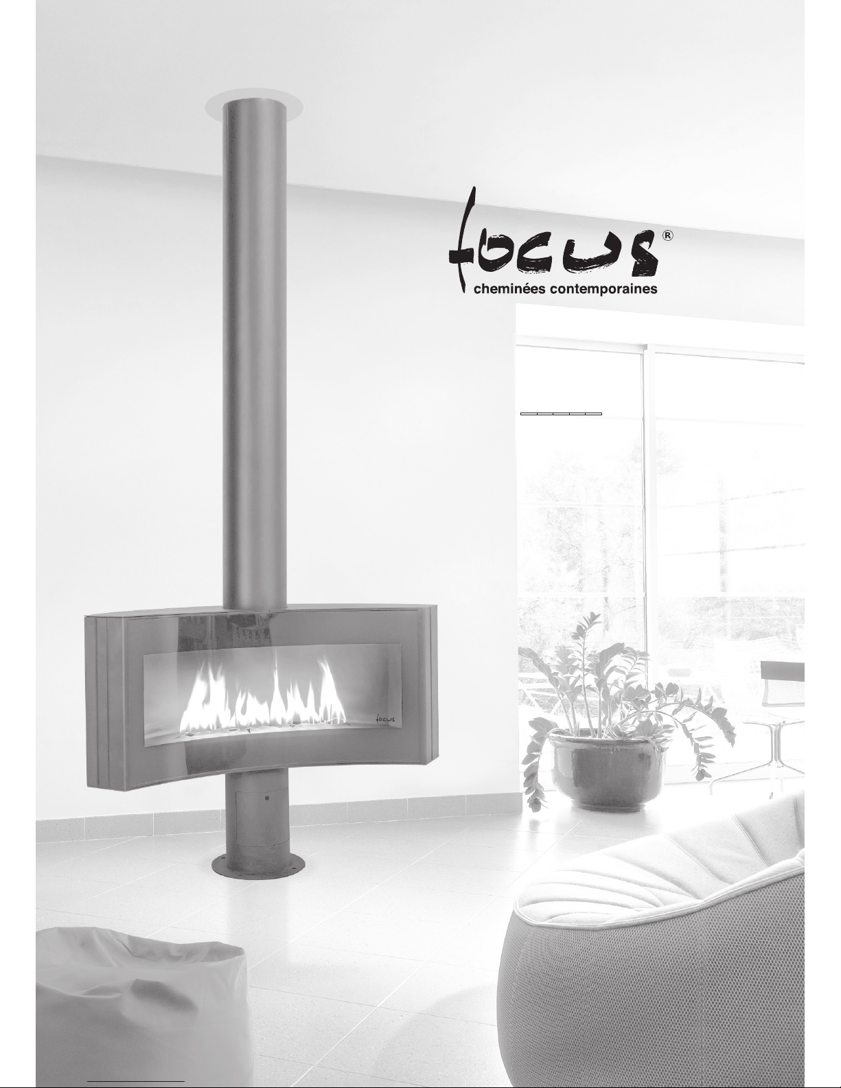
CURVIFOCUS
_____
INSTALLATION, SERVICING
AND USER INSTRUCTIONS
Page 2

02
This Focus gas appliance is a High Efficiency, Balanced Flue Live Fuel
Effect appliance. It provides radiant and convected heat using the latest
burner technology.
Before Installation, check that the local distribution conditions, nature of
the gas and pressure, and adjustment of the appliance are compatible.
This appliance is intended for use on a gas installation with a governed
meter.
This Gas Installation may only be installed by a registered professional
competent person (Gas Safe installer in the UK). The installation must
adhere to the requirements of the local and national Building regulations
and national standards. The installation manual must also be followed.
Ensure that the Flue Terminal is not in any way obstructed and is clear of
vegetation, i.e. trees, shrubs etc. and that no objects are leant against the
terminal or guard.
Always clean the Window Panel before the fire is ignited. Any finger prints
must be removed, as these will be burnt into the glass and will be unremovable.
Do not operate this appliance if the glass panel has been broken (or
cracked), removed or with firebox access panels open.
Only flue approved by Focus for this appliance may be used.
This appliance is a balanced flue product and is room sealed and as such
requires no additional ventilation for operation. However an adequate
supply of fresh air to maintain temperatures and a comfortable environment
is recommended.
This appliance is designed as a heating appliance, and as such will get
very hot in operation; all surfaces (except the controls and access door)
are considered to be working surfaces and as such should not be touched.
The front windows and surrounds are not considered to be fully secure
guards against accidental contact. It is recommended that an approved
fire screen be used if children, the elderly or persons with limited mobility
are to be present in the same area.
Do not place curtains, laundry, furniture etc. within a safe distance of
300mm of this appliance.
Do not attempt to burn rubbish on this appliance.
If this appliance is extinguished, on purpose or other, no attempt to relight
should be made within 3 minutes.
General NotesContent
General Notes
User instructions
EMERGENCY GAS ISOLATION
FIRST TIME OF OPERATION
OPERATING INSTRUCTIONS
A. GENERAL NOTES
B. SETTING THE ELECTRONIC CODE (first time use only)
C. SETTING FAHRENHEIT OR CELSIUS
D. SETTING THE TIME
E. CHILD PROOF
F. MANUAL MODE (handset)
G. DESIGNATED LOW FIRE AND HIGH FIRE
H. COUNTDOWN TIMER
I. MODES OF OPERATION
J. THERMOSTATIC MODE
K. PROGRAM MODE
L. AUXILIARY FEATURE
M. ECO MODE
MANUAL TURN OFF
CLEANING AND MAINTENANCE
Installation instructions
GAS CONNECTION
VENTILATION
APPLIANCE INSTALLATION
FLUE CONNECTION
A. GENERAL NOTES
B. TIMBER FRAME CONSTRUCTION
C. CARPORT OR BUILDING EXTENSION
D. BASEMENTS, LIGHTWELLS AND RETAINING WALLS
E. TERMINAL LOCATIONS
F. HORIZONTAL WALL VENT TERMINATION TYPE C11
G. VERTICAL ROOF VENT TERMINATION C31
H. FLUE RESTICTOR IDENTIFICATION
FUEL BED ARRANGEMENTS
A. FIREBOX ACCESS
B. LOG LAY
COMMISSIONING THE APPLIANCE
A. PILOT IGNITION CHECK
B. MAIN BURNER CHECK
C. PRESSURE CHECK
Servicing
CLEANING THE CERAMICS
SERVICING THE BURNER
SPARE PARTS
Technical Information
COUNTRIES OF USE
TECHNICAL DATA
DIMENSIONS
Appendix
MERTIK FAULT FINDING CHART
WIRING DIAGRAM
DECLARATION OF CONFORMITY
02
03
03
03
03
08
08
09
09
09
09
09
12
14
15
15
15
15
16
16
17
18
19
19
23
24
Page 3

03
EMERGENCY GAS ISOLATION
In the event of a gas leak or if gas is smelt, the appliance must be isolated.
This is done by turning OFF the gas at the Isolation Tap. This Isolation Tap
is located in the foot of the appliance, at the rear.
FIRST TIME OF OPERATION
Before igniting the appliance, ensure that all packaging, safety stickers
and any protective wrapping have been removed, and that the glass has
been cleaned, including all fingerprints from the glass.
Ensure that the room is adequately ventilated the first time that the
appliance is ignited; we would recommend opening windows if possible.
Run the appliance at full setting for a few hours so that the paint gets an
opportunity to fully cure. During this period it is possible for some fumes
and vapours to be given off. We would recommend keeping children and
pets out of the area at this time.
OPERATING INSTRUCTIONS
A. GENERAL NOTES
Wiring of valve and receiver must be completed before starting ignition.
Failure to do so could damage the electronics.
NOTICE
Batteries – Handset
· Low battery indicator on handsets.
Batteries – Receiver
· Low battery indication: frequent beeps for 3 seconds when motor turns.
· An AC mains adapter may be used instead of batteries.
· The module for fan speed control and light/dimmer includes mains
power together with batteries in the receiver for automatic backup in
case of power outage.
· Without using a mains adapter, battery replacement is recommended
at the beginning of each heating season.
· Old or dead batteries should be removed immediately. If left in the unit
the batteries can overheat, leak, and / or explode.
· Do NOT expose batteries (including during storage) to direct
sunlight, excessive heat, fire, moisture, or severe impact. Each of these
conditions can cause the batteries to overheat, leak, and / or explode.
· Batteries must be kept within their recommended temperature limits.
(Ambient battery temperature range: 32 °F to 131 °F [0 °C to 55 °C].)
· New and old batteries and different brands of batteries should not be
used together. Mixing of various batteries can cause the batteries
to overheat, leak, and / or explode.
WARNING
Software Version
Press
and buttons simultaneously. Software version is displayed.
Handset Model Number
Press
and buttons simultaneously. Handset model number
is displayed.
Deactivate Functions
1. Install batteries. All icons are displayed and flashing.
2. While the icons are flashing, press the relevant function button and hold
for 10 sec.
3. The function icon will flash until deactivation is complete. Deactivation
is complete when the function icon and two horizontal bars are displayed.
NOTE: If a deactivated button is pressed, there is no function, and two
horizontal bars are displayed.
NOTE: Deactivation remains in effect after change of batteries.
Activate Functions
1. Install batteries. All icons are displayed and flashing.
2. To activate a function, press the relevant button and hold for 10 sec.
3. The function icon will continue to flash until activation is complete.
Activation is complete when the function icon is displayed.
The following Functions can be Deactivated / Activated
· CHILD PROOF
· PROGRAM MODE
· THERMOSTATIC MODE (also deactivates PROGRAM MODE)
· ECO MODE
· LIGHT / DIMMER OPERATION
· CIRCULATING FAN OPERATION
· AUXILIARY FEATURE
· COUNTDOWN TIMER
B. SETTING THE ELECTRONIC CODE (First time use only)
Radio Frequency Handset
A code is selected automatically for all Mertik Maxitrol electronics from
among 65,000 codes available. The receiver must be paired with the
handset.
The receiver has to learn the handset code:
Press and hold the receiver’s reset button until you hear two (2) beeps. After
the second, longer beep, release the reset button. Within the subsequent
20 seconds press the button on the handset until you hear two (2) short
beeps confirming the code is set.
NOTE: This is a one time setting only, and it is not required when changing
the batteries In the handset or receiver.
User instructions
Page 4
04
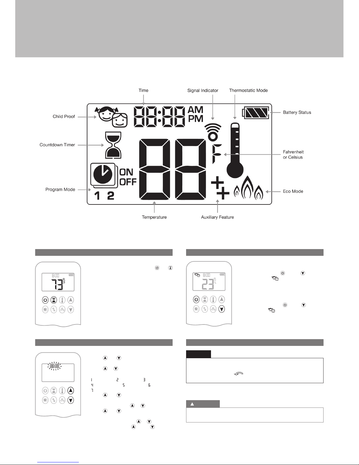
C. SETTING FAHRENHEIT OR CELSIUS
To change between °C and °F, press and
buttons simultaneously.
NOTE: Choosing °F results in a 12 hour clock.
Choosing °C results in a 24 hour clock.
D. SETTING THE TIME
1. Press and buttons simultaneously.
Day flashes.
2. Press or button to select a number to
correspond with the day of the week (e. g.
= Monday, = Tuesday, = Wednesday,
= Thursday, = Friday, = Saturday,
= Sunday).
3. Press and buttons simultaneously.
Hour flashes.
4. To select hour press or button.
5. Press and buttons simultaneously.
Minutes flash.
6. To select minutes press or button.
7. To confirm press and buttons
simultaneously or wait.
E. CHILD PROOF
ON:
To activate press and buttons
simultaneously. displayed and the
handset is rendered inoperable, except for the
off function.
OFF:
To deactivate press and buttons
simultaneously. disappears.
F. MANUAL MODE (handset)
BEFORE OPERATING
1 Make sure MANUAL knob on the GV60 valve is in the ON,
full counterclockwise
position.
2. Place the ON/OFF switch (if equipped) in the I (ON) position.
NOTICE
TO TURN ON FIRE
When pilot ignition is confirmed, motor turns automatically to maximum
flame height.
WARNING
Figure 01: 8-symbol Display
User instructions
Page 5
05
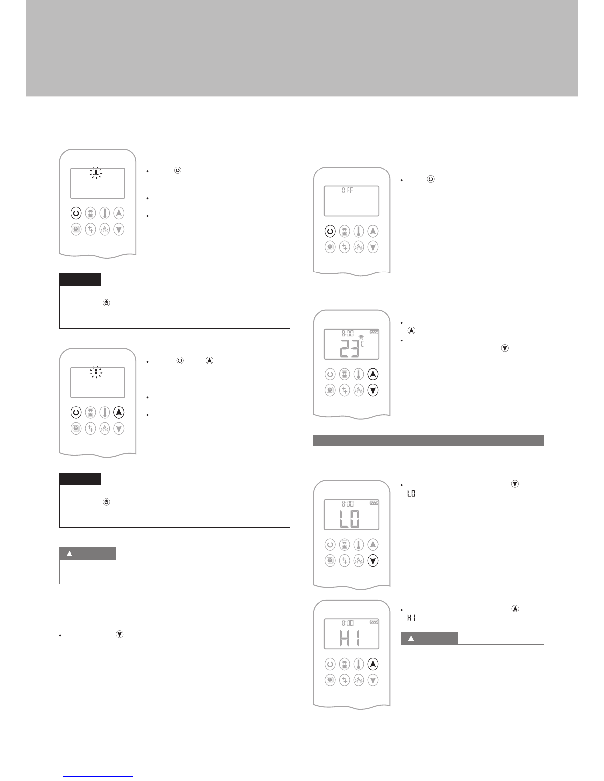
Handset One-Button Operation
(Default Setting)
· Press button until two short beeps and
a blinking series of lines confirms the start
sequence has begun; release button.
· Main gas flows once pilot ignition is
confirmed.
· Handset automatically goes into Manual
Mode after main burner ignition.
Change from one-button to two-button ignition operation by pressing
and holding
button for 10 sec. immediately after installing batteries.
ON is displayed and 1 is flashing. When change is complete 1 will
change to 2.
NOTICE
Handset Two-Button Operation
· Press and button simultaneously
until two short beeps and a blinking series
of lines confirms the start sequence has
begun; release buttons.
· Main gas flows once pilot ignition is
confirmed.
· Handset automatically goes into Manual
Mode after main burner ignition.
Change from two-button to one-button ignition operation by pressing
and holding
button for 10 sec. immediately after installing batteries.
ON is displayed and 2 is flashing. When change is complete 2 will
change to 1.
NOTICE
If the pilot does not stay lit after several tries, turn the main valve knob
to OFF (p. 08).
WARNING
STANDBY MODE (PILOT FLAME)
Handset
· Press and hold button to set appliance to pilot flame.
TO TURN OFF FIRE
Handset
· Press button to turn OFF.
NOTE: A new ignition is possible after the OFF
icon stops flashing.
FLAME HEIGHT ADJUSTMENT
Handset
· To increase flame height press and hold
button.
· To decrease flame height or to set appliance
to pilot flame, press and hold button.
G. DESIGNATED LOW FIRE AND HIGH FIRE
NOTE: Backlight must be on for high fire and low fire double-click
operation.
· To go to low fire, double-click button.
is displayed.
NOTE: Flame goes to high fire first before
going to low fire.
· To go to high fire, double-click button.
is displayed.
If the appliance will not operate, turn the main
valve knob to OFF (p. 08).
WARNING
User instructions
Page 6
06
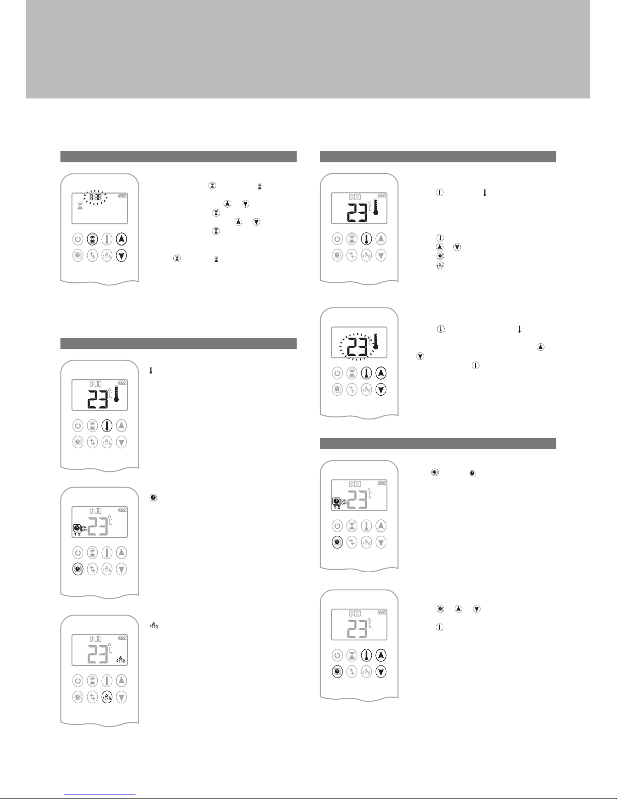
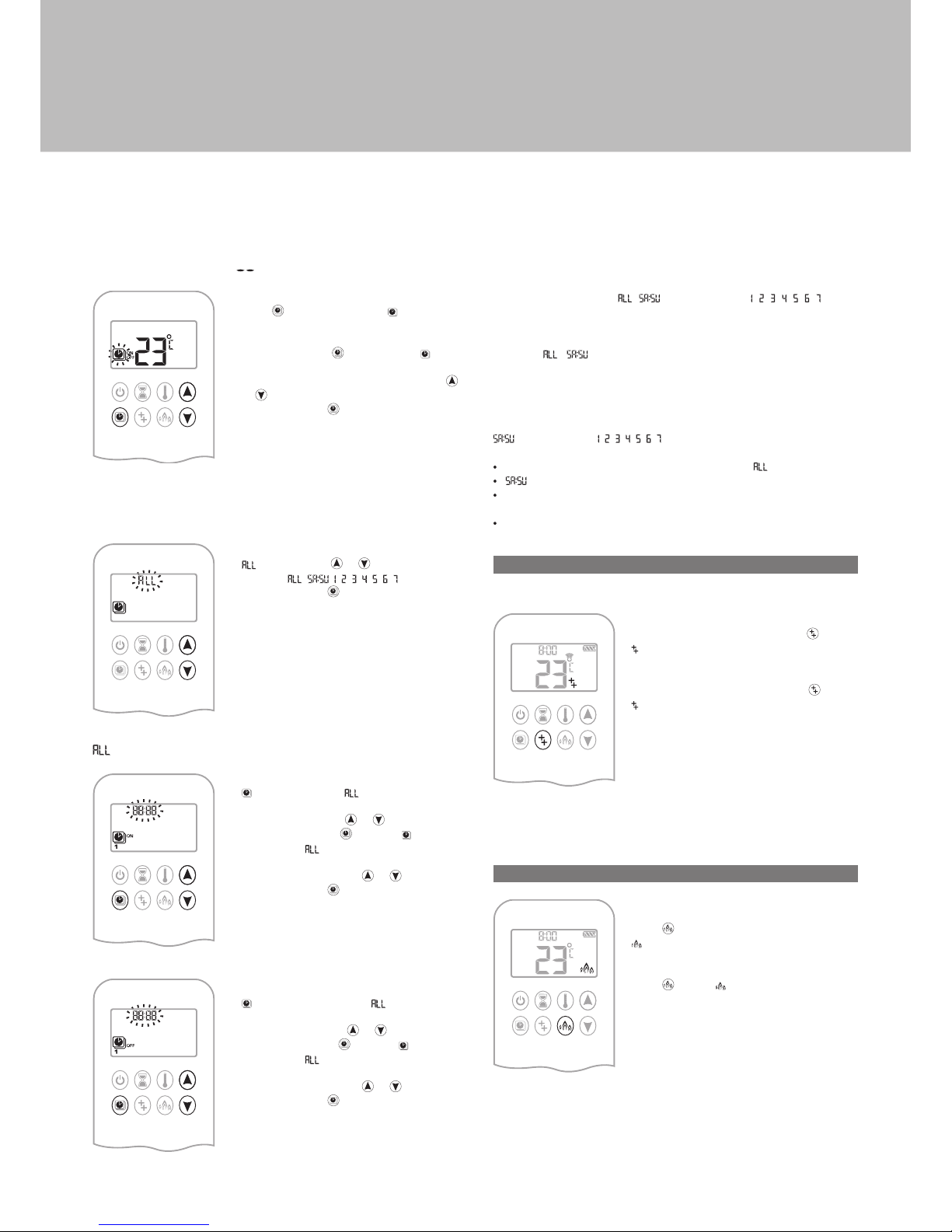
H. COUNTDOWN TIMER
ON/SETTING:
1. Press and hold button until displayed,
and hour flashes.
2. To select hour press or button.
3. To confirm press button. Minutes flash.
4. To select minutes press
or button.
5. To confirm press
button or wait.
OFF:
Press button, and countdown time
disappear.
NOTE: At end of countdown time period, the fire shuts off. The Countdown
Timer only works in Manual, Thermostatic, and Eco Modes.
Maximum countdown time is 9 hours and 50 minutes.
I. MODES OF OPERATION
Thermostatic Mode
The room temperature is measured and
compared to the set temperature. The flame
height is then automatically adjusted to
achieve the set temperature.
Program Mode
PROGRAMS 1 and 2, each can be
programmed to go on and off at specific times
at a set temperature.
Eco Mode
Flame height modulates between high
and low. If the room temperature is lower
than the set temperature, the flame height
stays on high for a longer period of time. If
the room temperature is higher than the set
temperature, the flame height stays on low
for a longer period of time. One cycle lasts
approx. 20 min.
J. THERMOSTATIC MODE
ON:
Press button. displayed, preset
temperature displayed briefly, and then room
temperature displayed.
OFF:
1. Press button.
2. Press or button to enter Manual Mode.
3. Press
button to enter Program Mode.
4. Press
button to enter Eco Mode.
SETTING:
1. Press button and hold until displayed,
temperature flashes.
2. To adjust set temperature press or
button.
3. To confirm press
button or wait.
K. PROGRAM MODE
ON:
Press
button. , 1 or 2 , ON or OFF
displayed.
OFF:
1. Press or or button to enter Manual
Mode.
2. Press
button to enter Thermostatic Mode.
NOTE: The set temperature for Thermostatic Mode is the temperature for
the on time in Program Mode. Changing the Thermostatic Mode set
temperature also changes the on time temperature in Program Mode.
User instructions
Page 7
07
Default settings:
ON TIME (Thermostatic) TEMPERATURE: 21 °C (70 °F)
OFF TIME TEMPERATURE: “
” (pilot flame only)
TEMPERATURE SETTING:
1. Press button and hold until flashes. ON
and set temperature (setting in Thermostatic
Mode) displayed.
2. To continue press
button or wait. , OFF
displayed, temperature flashes.
3. Select off temperature by pressing the
or
button.
4. To confirm press
button.
NOTE: The on (Thermostatic) and off set temperatures are the same for
each day.
DAY SETTING:
5.
flashes. Press or button to choose
between
, , , , , , , , .
6. To confirm press button.
selected
ON TIME SETTING (PROGRAM 1):
7.
, 1, ON displayed, is displayed shortly,
and hour flashes.
8. To select hour press
or button.
9. To confirm press button. , 1, ON
displayed, displayed shortly, and
minutes flash.
10. To select minutes press or button.
11. To confirm press button.
OFF TIME SETTING (PROGRAM 1):
12.
, 1, OFF displayed, is displayed
shortly, and hour flashes.
13. To select hour, press
or button.
14. To confirm press
button. , 1, OFF
displayed,
displayed shortly, and
minutes flash.
15. To select minutes press or button.
16. To confirm press button.
NOTE: Either continue to PROGRAM 2 and set on and off times or stop
programming at this point, and PROGRAM 2 remains deactivated.
NOTE: PROGRAM 1 and 2 use the same on (Thermostatic) and off
temperatures for , and Daily Timer ( , , , , , , ). Once
a new on (Thermostatic) and / or off temperature has been set, that
temperature becomes the new default setting.
NOTE: If
, or Daily Timer are programmed for PROGRAM 1
and PROGRAM 2 on and off times, these become the new default
times. The batteries must be removed to clear the PROGRAM 1
and PROGRAM 2 on and off times and temperatures.
or Daily Timer ( , , , , , , ) selected
· Set on time and off time using same procedure as “ selected” (above).
· : Set on time and off time for both Saturday and Sunday.
· Daily Timer: Unique on and off times may be set for a single day of
the week, for multiple days of the week, or for every day of the week.
· Wait to finish setting.
L. AUXILIARY FEATURE
Upon ignition burner 1 is on and burner 2 is in the last setting.
ON:
To switch a burner ON, press the
button.
displayed.
OFF:
To switch the burner OFF, press the button.
disappears.
NOTE: The latching solenoid valve cannot operate manually. If the receiver
battery runs down it will remain in the last operating position.
M. ECO MODE
ON:
Press
button to enter Eco Mode.
displayed.
OFF:
Press
button. disappears.
User instructions
Page 8
08
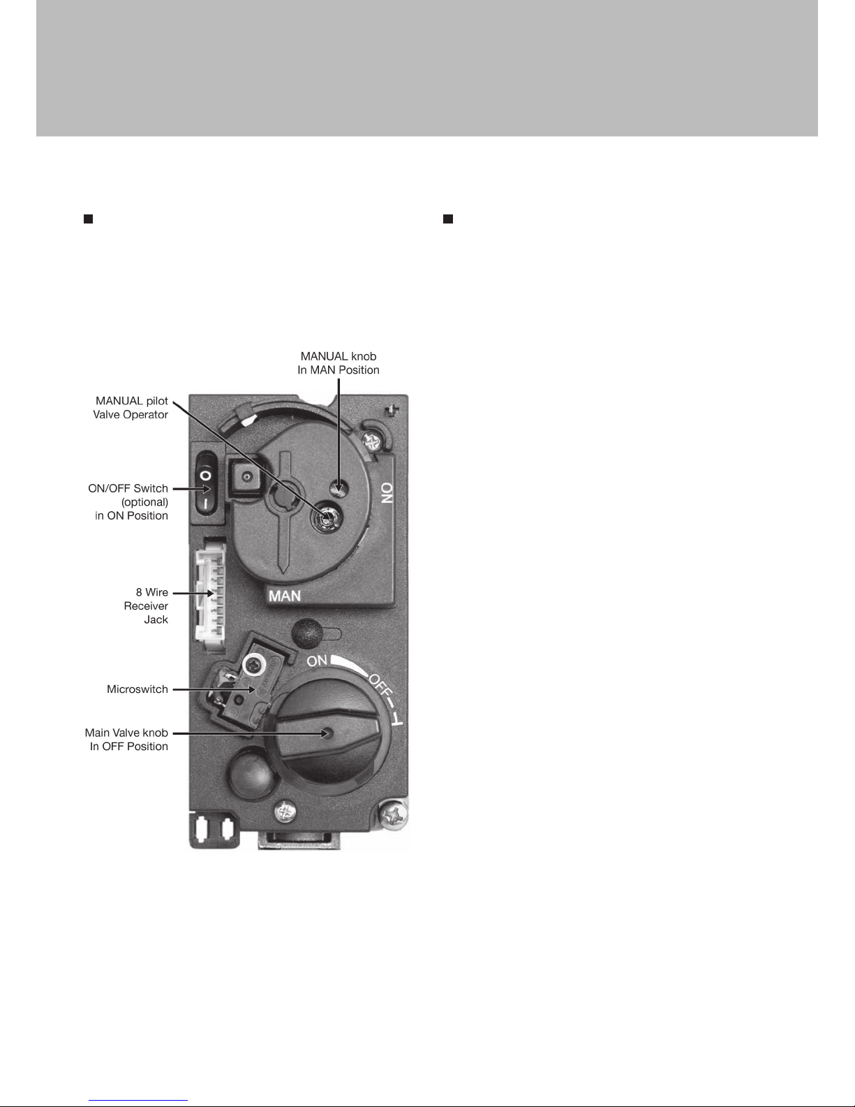
MANUAL TURN OFF
In the event that the appliance needs to be turned OFF manually,
for instance, if the remote control is lost or the batteries become totaly
flat, the control valve must be accessed and the switch flipped to OFF
(marked “0”).
The picture below shows the control valve.
On the Grappus, the control valve is located behind the control hatch
in the “Log Box”.
On the Slimfocus, the control valve is located in the foot of the appliance,
at the rear.
CLEANING AND MAINTENANCE
This appliance should be inspected and serviced once a year by a qualified,
competent and registered person. The inspection and maintenance must
at least ensure that the appliance is working correctly and safely. It is
advisable to clean the appliance of any dust and debris before regularly
during the heating season and especially if the appliance has not been
used for some time. This can be done with a soft brush and a vacuum
cleaner or a damp cloth and if required a non-abrasive cleaning agent. Do
not use corrosive or abrasive substances to clean the appliance.
User instructions
Page 9
09
Before commencing Installation, confirm that the details on the appliance
data plate correspond to the local distribution conditions, gas type and
pressure to which the appliance is to be installed.
Ensure that gas supply and supply pipe is capable of delivering the
required volume and pressure of gas and is in accordance with the rules
in force.
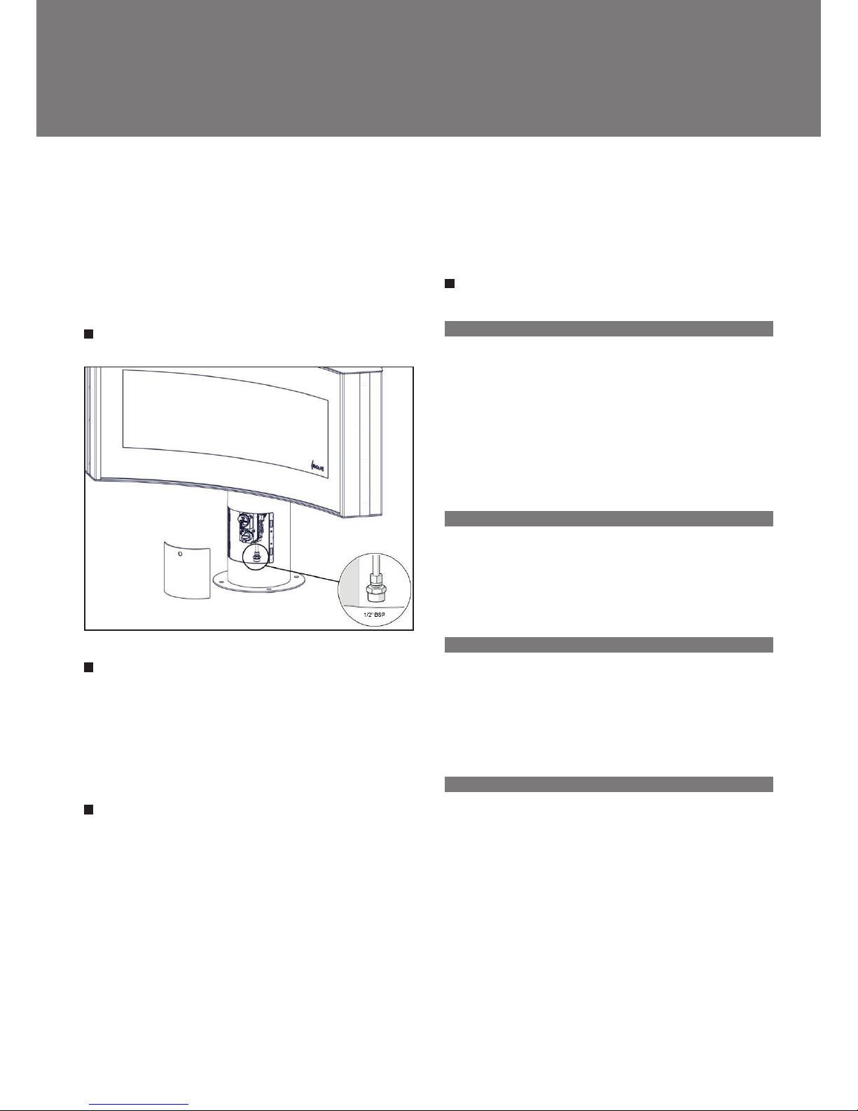
GAS CONNECTION
VENTILATION
This appliance is a Balanced Flue room sealed appliance, and as such
needs no additional ventilation. However an adequate supply of fresh air to
maintain temperatures and a comfortable environment is recommended.
This appliance may be installed in a completely sealed or mechanically
ventilated house.
APPLIANCE INSTALLATION
Determine the position required for the appliance.
Create a gas connection for the appliance in approximately the correct
location for the gas controls.
The gas controls are connected to the Burner of the appliance.
This appliance must be securely fixed to the floor using the fixings built
into the base of the appliance.
Do not make any adjustments to the appliance.
The appliance and Flue system should be fitted with a minimum clearance
of 500mm from any combustible objects or materials; this includes any
combustible materials used for the fireplace construction.
As this is a room sealed appliance and the appliance stands appropriately
and is securely fixed to the floor, a hearth is not required for this appliance.
A gap of 100mm should be left all round the appliance.
FLUE CONNECTION
A. GENERAL NOTES
This appliance may be installed with a roof terminal (C31) or a wall terminal
(C11).
This appliance may only be used with Balanced Flue (otherwise known
as Concentric Flue) parts as specified by Focus. The Focus specified flue
parts have been approved with the appliance. If the appliance is installed
on non-Focus approved parts, Focus cannot guarantee or accept and
responsibility for the proper and safe working of the appliance.
The flue system must be constructed from the appliance upwards, with all
joints being fully locked and sealed using the Focus specified parts.
B. TIMBER FRAME CONSTRUCTION
Whilst it is possible to install room-sealed appliances in timber frame
properties, great care needs to be taken to ensure that the flue assembly
does not interfere with the weather proofing qualities of any outer wall
which it may penetrate. Before attempting this work, further details need
to be referenced, (e.g. “Gas Installations in Timber Frame Buildings” from
the CORGI installer series in the UK).
C. CARPORT OR BUILDING EXTENSION
Where a flue terminal is sited within a carport or building extension, it
should have at least two completely open and unobstructed sides. The
distance between the lowest part of the roof and the top of the terminal
should be at least 600mm.
Note: A covered passageway should not be treated as a carport. Flues
should not be sited in a covered passageway between properties.
D. BASEMENTS, LIGHTWELLS AND RETAINING WALLS
Flue terminals should not be sited within the confines of a basement area,
light well or external space formed by a retaining wall, unless steps are
taken to ensure the products of combustion can disperse safely at all
times. It may be possible to install this Balanced Flue system in such a
location provided that it is not sited lower than 1m from the top level of that
area to allow combustion products to disperse safely.
Flue terminals should be sited to ensure total clearance of the combustion
products in accordance with the included information.
When the products of combustion are discharged, they should not cause a
nuisance to adjoining or adjacent properties and they should be positioned
so that damage cannot occur to other parts of the building. If the outer wall
surface is constructed of combustible material, a non-combustible plate
should be fitted behind the terminal projecting 25mm beyond the external
edges of the terminal.
Installation instructions
Page 10
10
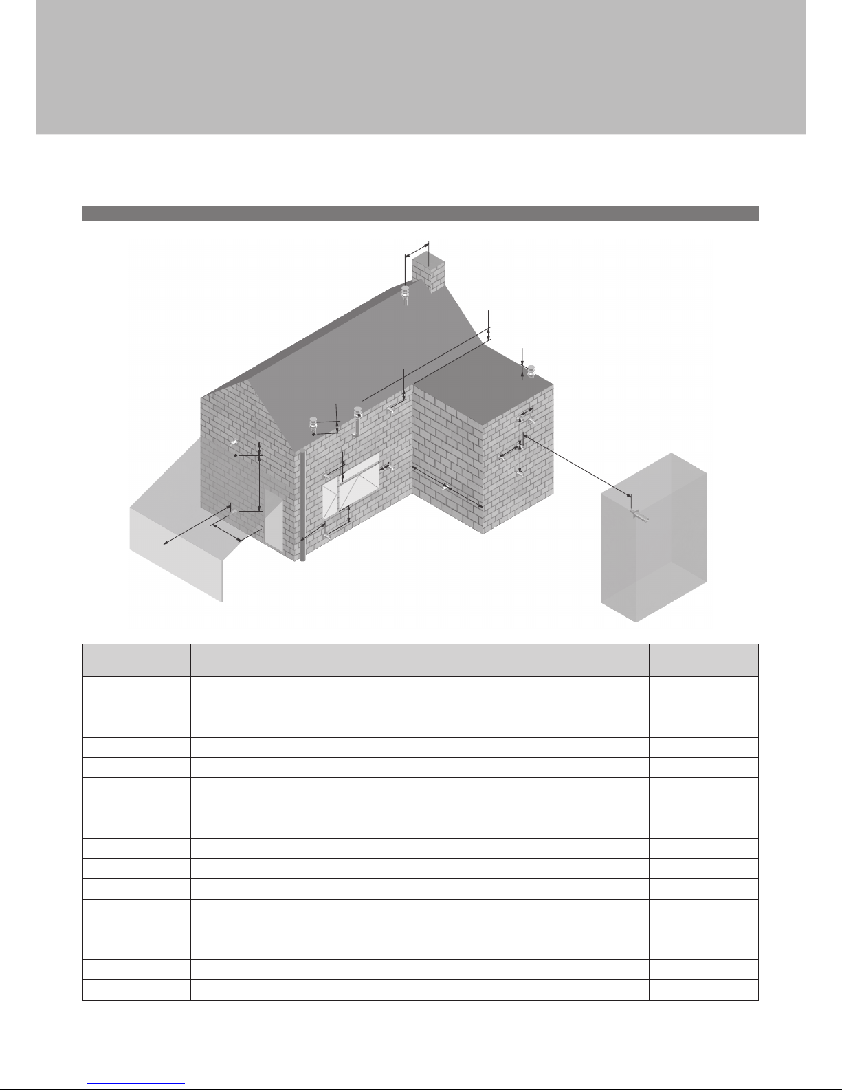
E. TERMINAL LOCATIONS
J
L
A
G
B
C
D,E
P
Q
H
H
Q
M M
N
K
N
Q
F
I
Dimension Terminal Position Distance (mm)
A*
Directly below an opening, air brick, opening window etc. 600
B Above an opening, air brick, opening window etc. 600
C Adjacent to an opening, air brick, opening window etc. 600
D Below gutters, soil pipes or drain pipes 300
E Below eaves 300
F Below balconies of car port roof 600
G From a vertical drain pipe or soil pipe 300
H From an internal or external corner 600
I Above ground roof or balcony level 300
J From a surface facing the terminal 600
K From a terminal facing the terminal 600
L From an opening in the car port (e.g. door , window into the dwelling) 1200
M Vertically from a terminal on the same wall 1500
N Horizontally from a terminal on the same wall 300
P From a vertical structure on the roof 600
Q Above intersection with roof 300
* I addition, the terminal should not be nearer than 300mm to an opening in the building fabric formed for the purpose of accommodating a built in element
such as a window frame.
Installation instructions
Page 11
11
F. HORIZONTAL WALL VENT TERMINATION TYPE C11
Flue sizing: · Ø100/150 Connector on Appliance for Poujoulat PGI
concentric flue system.
· Ø100/150 Adaptor for Metaloterm Ontop or Muelink
& Grol concentric flue systems.
· Ø100/150 Maybe used Through-out
Flue Terminal: · Ø100/150
Maximum pipe extension, for outside wall (H).
Curvifocus = 3 X Vertical Pipe Rise (V) . For Ø100/150 flue.
Maximum Permissable run (H) see table below.
Vertical Flue Rise
(V) metres
Max. Horizontal Flue Run, (H) m
for Ø100/150 flue
0.5 1.5
1 3
1.5 4.5
2 6
2.5 7.5
3 9
3.5 10.5
4 12
4.5 12
5 12
5.5 12
6.5 12
7 12
7.5 and over 12
Minimum Vertical Flue Height: 0.5m
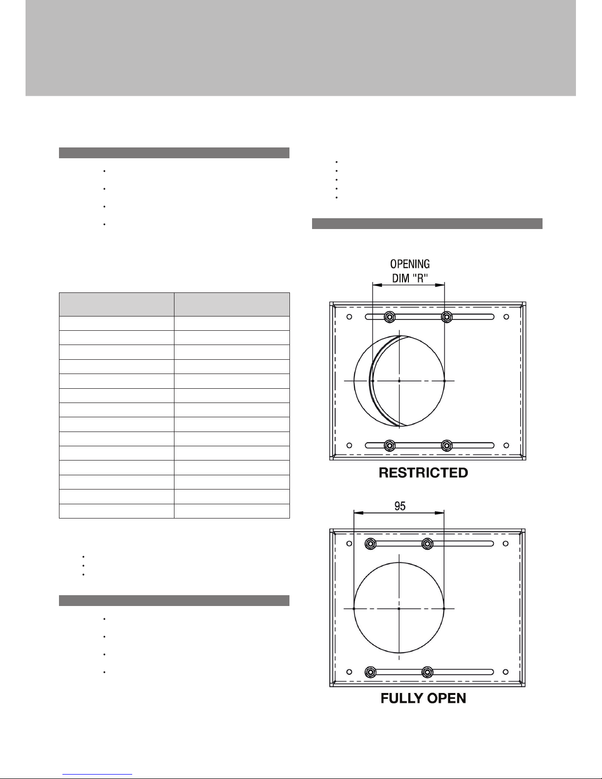
Flue Restrictors to be fitted:
· V/H > 0.5, opening “R” = 75mm.
· 0.5 ≤ V/H ≤ 0.4, opening “R” = 65mm.
· V/H < 0.4, opening “R” = fully open.
G. VERTICAL ROOF VENT TERMINATION C31
Flue sizing: · Ø100/150 Connector on Appliance for Poujoulat PGI
concentric flue system.
· Ø100/150 Adaptor for Metaloterm Ontop or Muelink &
Grol concentric flue systems.
· Ø100/150 Maybe used Through-out
Flue Terminal: · Ø100/150
Minimum Vertical Flue Height: 0.5m
Maximum Vertical Flue Height: 15m
Flue calculations when using elbows (0-90° permissible), total flue length
maximum = 15m and each bend will equate to ½m, Vertical rise (V) must
be at least twice the Horizontal run (R), i.e. V=2H (or H/V≤½).
Flue Restrictors to be fitted:
· Ø100/150 Vertical Rise < 2m, Opening “R” = 75mm.
· Ø100/150 Vertical Rise = 2-5m, Opening “R” = 55mm.
· Ø100/150 Vertical Rise = 5-7m, Opening “R” = 65mm.
· Ø100/150 Vertical Rise = 7-12m, Opening “R” = 85mm.
· Ø100/150 Vertical Rise > 12m, Opening “R” = Fully Open.
H. FLUE RESTRICTOR IDENTIFICATION
NOTE: Fully open, dimension “R” = 95mm
Installation instructions
Page 12
12
FUEL BED ARRANGEMENTS
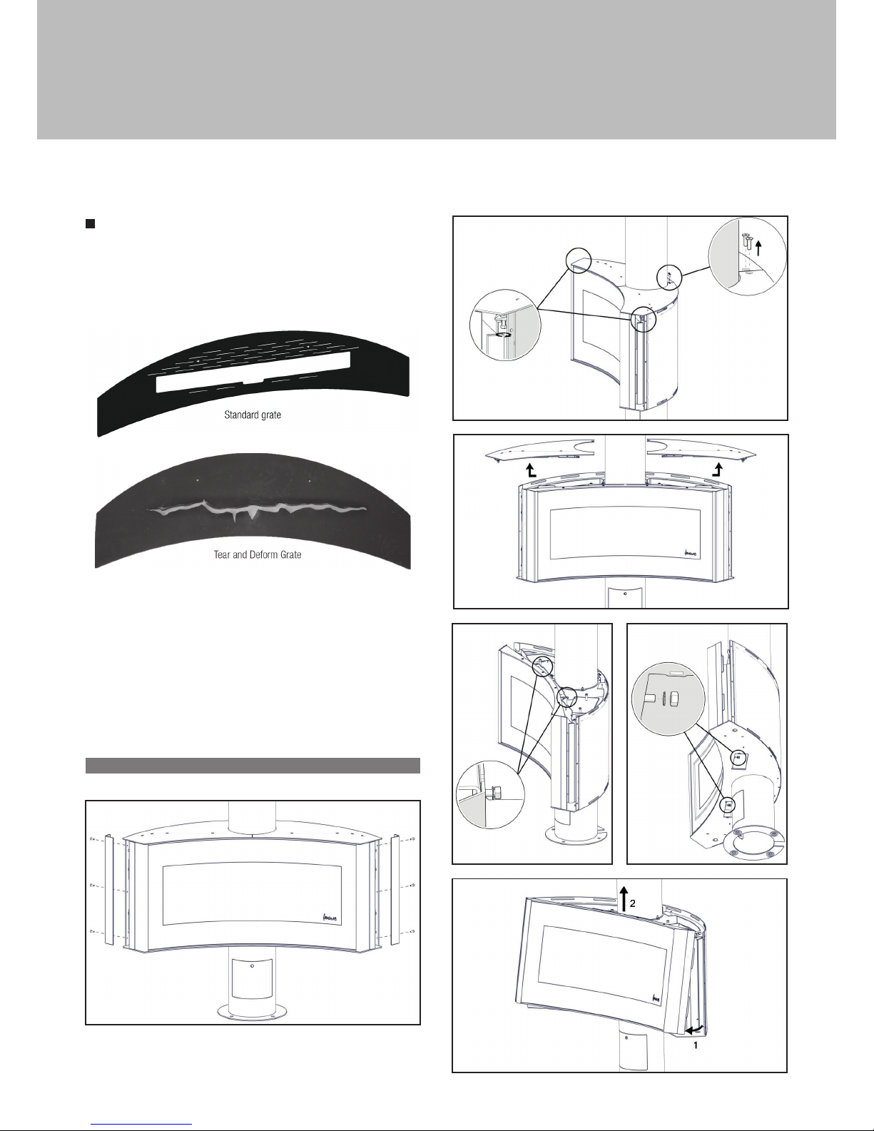
Curvifocus is available with 2 Grate options, a “Standard Grate” and
a “Tear and Deform Grate”.
Shown below are these Grate options.
These Grate options can all be used in the appliance without any further media.
The Log options are only available with the “Standard Grate” options.
When arranging the Media into the Firebed, it is imporant that
the Pilot area is kept clear and that no Media enters the Pilot shield.
The Pilot area includes the pilot shield and the top of the burner to the first
slot inside the fence of the pilot shield.
When comissioning or servicing the Appliance Cross Lighting must be
checked to ensure smooth lighting of the main burner from the Pilot
Flame and smooth lighting of the effect burners from the main Burner.
A. FIREBOX ACCESS
Installation instructions
Page 13
13
B. LOG LAY
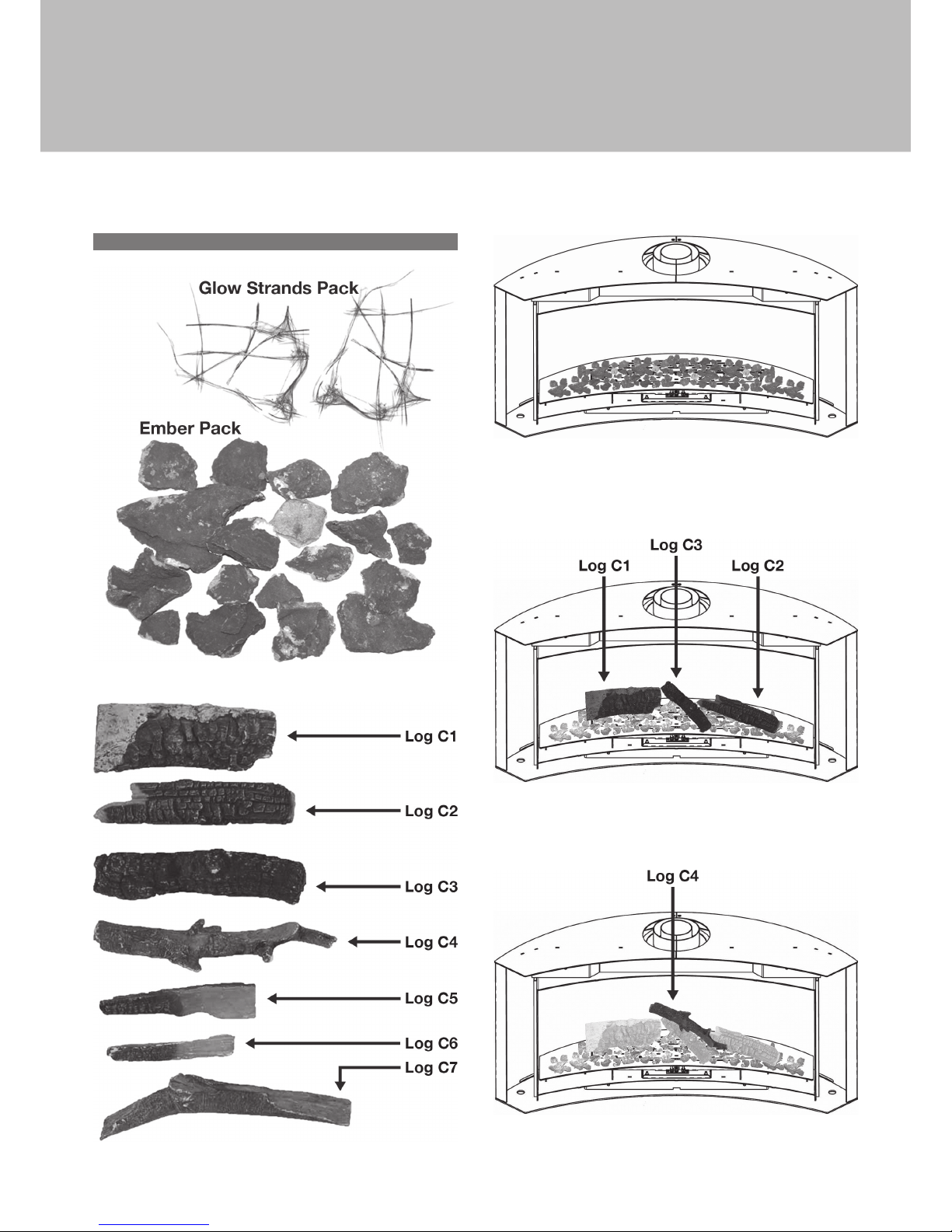
Scatter the Bags of Embers over the top of the burners as shown, keeping
the piot area clear.
Position Logs C1, C2, & C3 as shown in the diagram.
Position Log C4 as shown in the diagram.
Installation instructions
Page 14
14
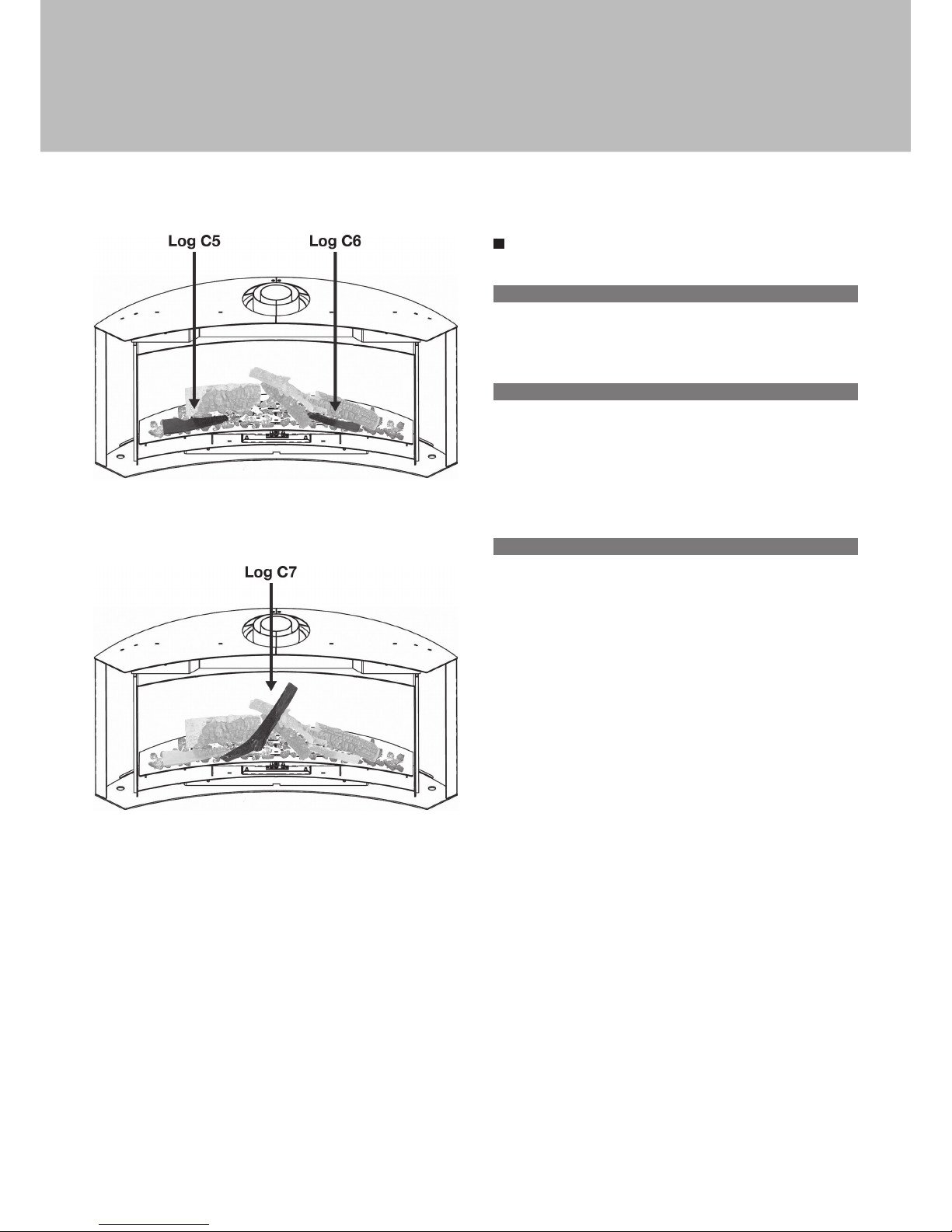
Position Logs C5, & C6 as shown in the diagram.
Position Log C7 as shown in the diagram.
COMMISSIONING THE APPLIANCE
A. PILOT IGNITION CHECK
1. Ignite the pilot light as described in the User Instructions
2. Check that the pilot flame stays alight
3. Extinguish the pilot light
B. MAIN BURNER CHECK
1. Ignite the pilot light as described in the User Instructions
2. Turn on the main burner as described in the User Instructions
3. Check that the pilot smoothly cross-lights to the main burner and that
the main burner and pilot stay alight
4. Check the operation of the «effect» burners as described in the User
Instructions
5. Extinguish the appliance fully
C. PRESSURE CHECK
The appliance is preset to give the correct heat inputs as listed in the
technical details. No further adjustment is necessary. Always check the
inlet pressure and burner pressure.
1. Turn off the gas valve on the appliance
2. Release the screw on the Inlet Pressure test point on the gas valve and
connect a manometer
3. Check that the measured pressure is as the prescribed supply pressure
4. Perform the test when the appliance is burning on full (inc. «effect»
burners) and with only the pilot alight
5. If the pressure is low, check the gas supply pipes are too a correct sizing
6. If the pressure is too high (more than 5 mbar over) the appliance may be
installed, but the gas supply company should be contacted
7. Release the screw on the Burner Pressure test point on the gas valve
and connect a manometer
8. Check that the measured pressure is as detailed in the Technical details
9. The measured value should be within +/- 10% of the described value.
If this is not the case, please contact the supplier.
NOTE: After checking the pressures and removing the manometers,
the screws in the Pressure Test points must be closed, and
the system must be checked for gas-tightness
Installation instructions
Page 15

15
Turn the appliance OFF and isolate the gas supply. Ensure the appliance
is fully cold before attempting to start servicing the appliance. No liability
can be accepted by Focus for injury caused by burning or scolding by a
hot appliance.
A suggested procedure for servicing is listed below.
A. Lay out dust sheet on flooring, mask off any special fireplace materials.
B. Open Outer Firebox Access Door.
C. Remove Inner Access Door.
D. Carefully remove the Ceramic components (including Embers)
or Gravels
E. Use a Vacuum cleaner to clean the top of the burners and grate
F. Remove Grate
G. Use the vacuum cleaner and a soft brush to clean the pilot assembly
and both Injectors. It may be easier to access the Injector by
removing the Throttle. Never modify or bend the Thermocouple.
H. Clean the Window Panel.
I. Turn on the gas supply and check for leaks, check the burners and
Pilot for good condition and operation
J. Replace Grate
K. Replace the Firebed arrangements
L. Replace the access doors.
M. Check the flue system and terminal, making sure that the terminal
vent is fully clear
N. Light the appliance and test setting pressures
O. Check the safe operation of the appliance.
CLEANING THE CERAMICS
Remove the ceramics as detailed in A - E above.
Gently clean the ceramics in the open air, using a soft brush and a vacuum
cleaner. Where necessary replace damaged components only with
genuine Focus specified parts. Seal any scrap ceramics in plastic bags
and dispose at proper refuse sites. When using a vacuum cleaner, it is
recommended that one with a HEPA filtering system is used.
Re-fit the Firebed arrangement, re-seal the appliance and check the safe
operation of the appliance.
SERVICING THE BURNER
A fault finding chart is included in the appendix for the Mertik control
system fitted to this appliance.
Access the Burner as detailed in A - F above.
The pilot is now clearly visible, the pilot, including the Thermocouple,
can be replaced/serviced by removing raising the pilot assembly from its
mounting. This is done by removing the two screws on the surface of the
pilot. The fittings on the under-side of the pilot can be un-done using a
10mm spanner where appropriate.
The Main Burner Injectors can be accessed from the underside of the
appliance. If the burner requires to be removed, this may be done by
removing the 4 M6 fixings inside the firebox (10mm Spanner), the burner
will lift out through the Firebox.
When replacing any parts use only original Focus specified parts.
SPARE PARTS
Item Curvifocus
Window Panel xxxxxxx
Ceramic Log Pack xxxxxxx
Ember Pack xxxxxxx
Gravel Pack xxxxxxx
Pilot Assembly Natural xxxxxxx
Pilot Assembly LPG xxxxxxx
Electrode xxxxxxx
Electrode Lead xxxxxxx
Thermocouple xxxxxxx
Injector Natural Front xxxxxxx
Injector Natural Rear N/A
Injector LPG Front xxxxxxx
Injector LPG Rear N/A
Complete Burner Assembly Natural xxxxxxx
Complete Burner Assembly LPG xxxxxxx
Burner Seal xxxxxxx
Grate Assembly Standard xxxxxxx
Grate Assembly Tear & Deform xxxxxxx
Gas Valve Assembly Natural xxxxxxx
Gas Valve Assembly LPG xxxxxxx
Latching Solenoid N/A
Receiver unit xxxxxxx
Handset xxxxxxx
Access Door Assembly xxxxxxx
Servicing
Page 16

16
COUNTRIES OF USE
Country Natural LPG
AT -Austria I2H, G20 at 20 mbar I3P(50),G31 at 50 mbar; I3B/P(50),G30/G31 at 50 mbar
BE -Belgium I2E+, G20/G25 at 20/25 mbar I3+,G31/G31 at 28/37 mbar; I3P(37),G31 at 37 mbar; I3B/P(30),G30/G31 at 30 mbar
BG -Bulgaria I2H, G20 at 20 mbar I3B/P(30),G30/G31 at 30 mbar
CH - Switzerland I2H, G20 at 20 mbar I3P(50),G31 at 50 mbar; I3+,G31/G31 at 28/37 mbar; I3P(37),G31 at 37 mbar; I3B/P(50),
G30/G31 at 50
CY -Cyprus I2H, G20 at 20 mbar I3+,G31/G31 at 28/37 mbar; I3B/P(30),G30/G31 at 30 mbar
CZ -Czech Republic I2H, G20 at 20 mbar I3P(50),G31 at 50 mbar; I3+,G31/G31 at 28/37 mbar; I3P(37),G31 at 37 mbar; 3B/P(50),
G30/G31 at 50
DE -Germany I2ELL, G25 at 20 mbar¹; I2E,
G20 at 20 mbar
I3P(50),G31 at 50 mbar; I3B/P(50),G30/G31 at 50
DK -Denmark I2H, G20 at 20 mbar I3B/P(30),G30/G31 at 30 mbar
EE -Estonia I2H, G20 at 20 mbar I3B/P(30),G30/G31 at 30 mbar
ES -Spain I2H, G20 at 20 mbar I3+,G31/G31 at 28/37 mbar; I3P(37),G31 at 37 mbar
FI -Finland I2H, G20 at 20 mbar I3P(30),G31 at 30 mbar; I3B/P(30),G30/G31 at 30 mbar
FR -France I2E+, G20/G25 at 20/25 mbar I3+,G31/G31 at 28/37 mbar; I3P(37),G31 at 37 mbar; I3B/P(30),G30/G31 at 30 mbar;
I3B/P(50),G30/G31 at 50
GB -United Kingdom I2H, G20 at 20 mbar I3+,G31/G31 at 28/37 mbar; I3P(37),G31 at 37 mbar; I3B/P(30),G30/G31 at 30 mbar
GR -Greece I2H, G20 at 20 mbar I3+,G31/G31 at 28/37 mbar; I3P(37),G31 at 37 mbar; I3B/P(30),G30/G31 at 30 mbar
HU -Hungary I3B/P(30),G30/G31 at 30 mbar
HR -Croatia I2H, G20 at 20 mbar I3P(37),G31 at 37 mbar; I3B/P(30),G30/G31 at 30 mbar
IE -Ireland I2H, G20 at 20 mbar I3+,G31/G31 at 28/37 mbar; I3P(37),G31 at 37 mbar
IS -Iceland
IT -Italy I2H, G20 at 20 mbar I3+,G31/G31 at 28/37 mbar; I3P(37),G31 at 37 mbar; I3B/P(30),G30/G31 at 30 mbar
LT -Lithuania I2H, G20 at 20 mbar I3+,G31/G31 at 28/37 mbar; I3P(37),G31 at 37 mbar; I3B/P(30),G30/G31 at 30 mbar
LU -Luxembourg I2E, G20 at 20 mbar
LV -Latvia I2H, G20 at 20 mbar
MT -Malta I3B/P(30),G30/G31 at 30 mbar
NL -The Netherlands I2L, G25 at 25 mbar I3P(50),G31 at 50 mbar; I3P(30),G31 at 30 mbar; I3P(37),G31 at 37 mbar; I3B/P(30),
G30/G31 at 30 mbar
NO -Norway I2H, G20 at 20 mbar I3B/P(30),G30/G31 at 30 mbar
PL -Poland I2E, G20 at 20 mbar I3P(37),G31 at 37 mbar
PT -Portugal I2H, G20 at 20 mbar I3+,G31/G31 at 28/37 mbar; I3P(37),G31 at 37 mbar
RO -Romania I2E, G20 at 20 mbar I3P(30),G31 at 30 mbar; I3B/P(30),G30/G31 at 30 mbar
SE - Sweden I2H, G20 at 20 mbar I3B/P(30),G30/G31 at 30 mbar
SL -Slovenia I2H, G20 at 20 mbar I3+,G31/G31 at 28/37 mbar; I3P(37),G31 at 37 mbar; I3B/P(30),G30/G31 at 30 mbar
SK -Slovakia I2H, G20 at 20 mbar I3P(50),G31 at 50 mbar; I3+,G31/G31 at 28/37 mbar; I3P(37),G31 at 37 mbar; I3B/
P(30),G30/G31 at 30 mbar; I3B/P(50),G30/G31 at 50
TR -Turkey I2H, G20 at 20 mbar I3+,G31/G31 at 28/37 mbar; I3P(37),G31 at 37 mbar; I3B/P(30),G30/G31 at 30 mbar
Technical Information
Page 17
17
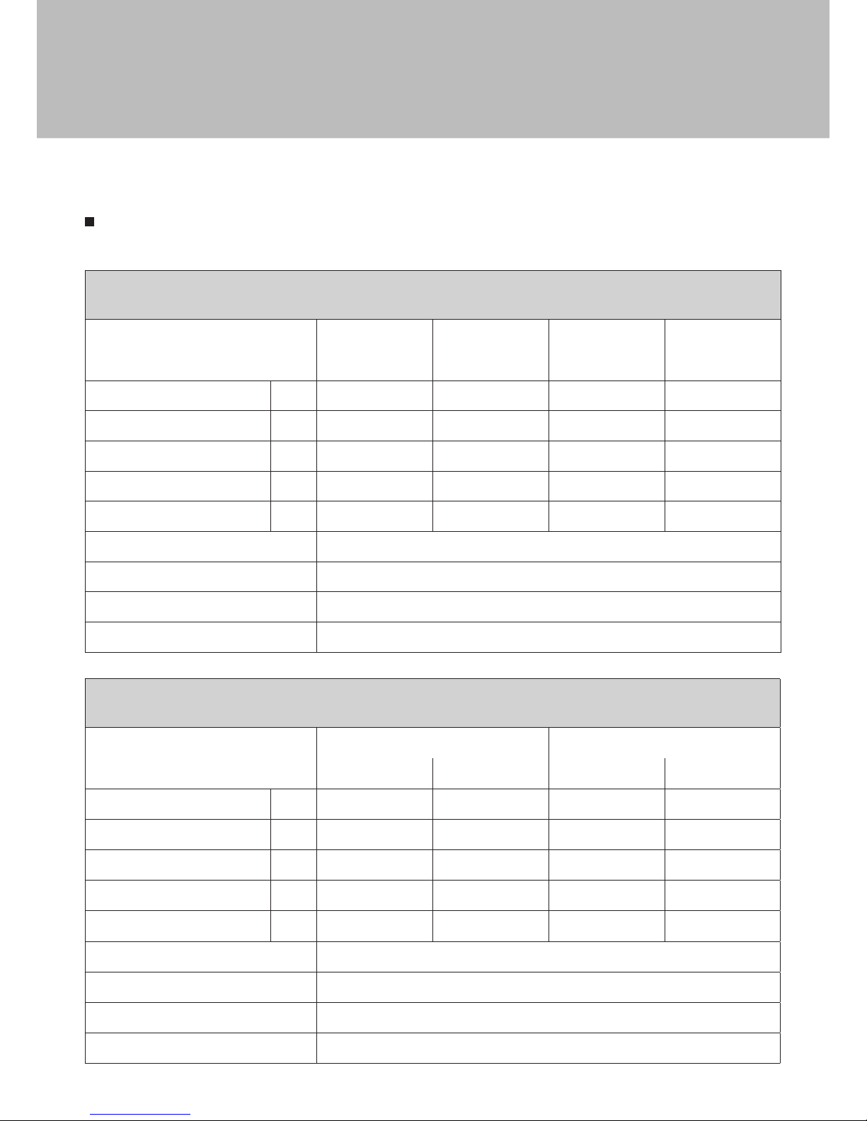
TECHNICAL DATA
Product Identification Number : 0359CQ0657
Curvifocus Natural
Gas type
G20
I2H,I2E
G20/G25
I2E+
G20/G25
I2ELL
G25
I2L
Supply Pressure mbar 20 20/25 20 25
Nominal Heat Input Gross (Hs) kW 9 9 9 / 7.3 8
Nominal Heat Input Nett (Hi) kW 8.1 8.1 8.1 / 6.6 7.2
Consumption m³/hr 0.843 0.843/0.723 0.843/0.794 0.892
Burner Pressure (hot) mbar 14.2 14.2/17.8 14.2 17.8
Injector Marking 650
Pilot 446.1385.44
Efficiency Class 2
Nox Class 5
Curvifocus LPG
Gas type
G
30/G31 G31
I3B/P(30/50) I3+ I3P (37,50) I3P(30)
Supply Pressure mbar 30/50 28‐30/37 37/50 30
Nominal Heat Input Gross (Hs) kW 7.5 7.5 7.5 6.5
Nominal Heat Input Nett (Hi) kW 6.9 6.9 6.9 6.0
Consumption m³/hr 0.207 0.207 0.270 0.231
Burner Pressure (hot) mbar 28.7 28.7 36.6 29.6
Injector Marking 220
Pilot 446.1385.24
Efficiency Class 2
Nox Class 5
Technical Information
Page 18
18
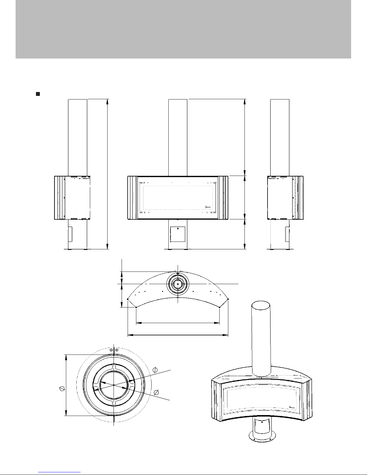
DIMENSIONS
360 521 919
1800
150 280
1203
1000
A
100
150
219
DETAIL A
CURVIFOCUS
Technical Information
Page 19

19
MERTIK FAULT FINDING CHART
FUNCTION POSSIBLE CAUSE REMEDY
1
HANDSET START:
Press both buttons
to start ignition (IGN)
sequence. Beep will
occur each second.
No
Transmitter batteries low.
Replace transmitter batteries.
9V quality alkaline recommended.
Receiver batteries low.
Replace receiver batteries with 1.5V “AA” quality
alkaline batteries.
Optional mains adapter not operating properly. Check mains adapter.
OK
Check coding of transmitter and receiver. (Initial sync.
)
Learn new code (reset).
See label on receiver.
Transmitter distance limited.
1. Straighten the antenna.
2. Replace receiver.
See wiring diagram, p. 23.
2
Magnet unit is
energized (audible
thud to detect
functionality).
No
No beep
Impulse magnet not
operating properly.
Replace gas valve.
No
3 short
beeps
Low batteries.
Replace receiver batteries with 1.5V “AA” quality
alkaline batteries.
No
1 long
beep
ON/OFF switch
in OFF position.
Switch to ON.
OK
8-wire cable Off/not
operating properly.
Check 8-wire cable.
SW-cable disconnected.
Check cable connection.
See figure 1 on page 23.
Motor not operating
properly.
Replace gas valve.
Micro switch not
operating properly.
Replace gas valve.
Appendix
Page 20

20
FUNCTION POSSIBLE CAUSE REMEDY
3
Spark will occur
each second.
No
Ignition components not operating properly.
Check connection between cable & IGNelectrode.
See wiring diagram, p. 23.
Check IGN-electrode spark gap.
See wiring diagram, p. 23.
Check IGN-electrode.
See wiring diagram, p. 23.
Check IGN-cable for damage.
See wiring diagram, p. 23.
Increase distance between IGN-cable and all
metal parts. Shorten IGN-cable if possible or
cover, e.g. silicon hose.
See wiring diagram, p. 23.
No
IGN-sequence stops, no pilot flame. No reaction
to transmitter command. (Controller crashes.)
Press RESET button.
See “Setting the Electronics Code” p. 3.
Add ground wire between pilot burner and valve.
See wiring diagram, p. 23.
Do not coil the IGN-cable.
Shorten IGN-cable if possible (no longer than 900 mm).
See wiring diagram, p. 23.
No
IGN-sequence stops, no pilot flame.
Transmitter command is possible.
Replace receiver batteries with 1.5V “AA” quality
alkaline batteries.
OK
Appendix
Page 21
21
FUNCTION POSSIBLE CAUSE REMEDY
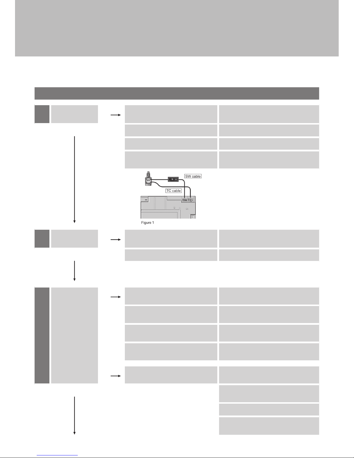
4
Pilot lit. No TC- and SW-cable reversed.
Check connection of cable to receiver and
interrupter. See figure 1.
OK
Magnet unit not operating properly. Replace gas valve or (magnet unit).
Short between interrupter and SW-cable. Check connection to interrupter.
No gas (magnet unit drops after 30 second
audible count).
Check gas supply.
5
Sparking stops after
pilot is lit.
No Short between interrupter and TC-cable. Check connection to interrupter. See figure 1.
OK
Electronic measuring amplifier defective. Replace Receiver. See wiring diagram, p. 23.
6
Motor turns to main
gas and pilot stays
lit.
No
Resistance in thermo current circuit too high.
Check cable in thermo-current circuit.
See wiring diagram, p. 23.
Magnet
unit
drops
(audible
sound).
Not enough heat on thermocouple.
Check position of pilot to thermocouple and
intensity of pilot flame.
Low voltage from thermocouple.
Replace thermocouple Do not overtighten (hand
tight +1/4 turn max).
Short because thermocouple end is damaged
or not centered.
Replace thermocouple. Do not overtighten (hand
tight +1/4 turn max).
No
IGN-sequence stops. No reaction to
transmitter command (Controller crashes).
Press RESET button.
See “Setting the Electronics Code” p. 23.
OK
Add ground wire between pilot burner and valve.
See wiring diagram, p. 23.
Do not coil the IGN-cable.
Shorten IGN-cable if possible (no longer than 900 mm).
See wiring diagram, p. 23.
Appendix
Page 22

22
FUNCTION POSSIBLE CAUSE REMEDY
7
Main burner is lit. No Manual knob in “MAN” position.
Turn manual knob to “ON” position (positive latch
is required). See “Manual Operation” p. 08.
OK
8
Main burner stays lit. No
Too much draft at pilot (poor flame
impingement of thermo-couple).
Check installation.
OK
9
Magnet unit drops
while motor turns.
3 beeps.
No Low batteries.
Replace receiver batteries with 1.5V “AA” quality
alkaline batteries.
System can be
switched OFF via the
electronics.
No
System CAN be
switched OFF via
ON/OFF switch.
No
Short in interrupter
between TC- and
SW- cable.
Check connection to interrupter block.
See wiring diagram, p. 23.
YES
OK
YES
OK
Replace gas valve (magnet unit [CE only]).
Appendix
Page 23
23
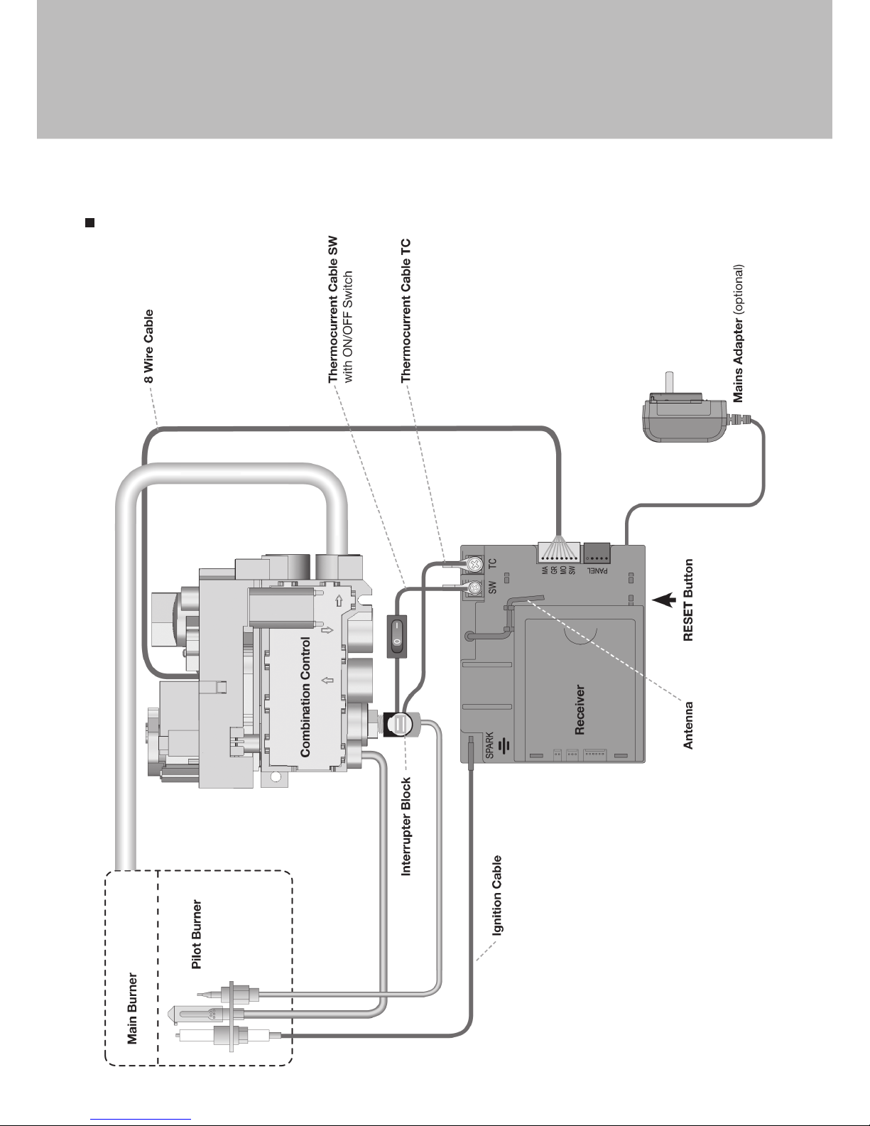
WIRING DIAGRAM
Appendix
Page 24

24
DECLARATION
OF CONFORMITY
ATELIER DOMINIQUE IMBERT s.a.s.
3 Impasse Claque Patin
F - 34380 Viols le Fort
declares that the FOCUS independent gas fired convection heaters described here
are in accordance with the appliances described in the EC-Type Examination
Certificate No. UK-LHD-0359-0657R1 delivered by INTERTEK and comply with the
essential requirements applicable to EN 613 :2001 + A1 :2008 and Regulation UE
2016/426.
Signed for and behalf of the manufacturer by :
Laurent Gaborit
Directeur Général
Viols le Fort, le 14 octobre 2016
Appendix
Page 25

25
Note
Page 26

26
Note
Page 27

27
Note
Page 28

V. 01 - March 2017
Création - Édition - Distribution :
Atelier dominique imbert
S.A.S. au capital de 102 355 euros
34380 Viols-le-Fort
France
Tel. : 00 33 (0)4 67 55 01 93
Fax. : 00 33 (0)4 67 55 77 77
Web : www.focus-creation.com
Email : [email protected]
 Loading...