

Page 1
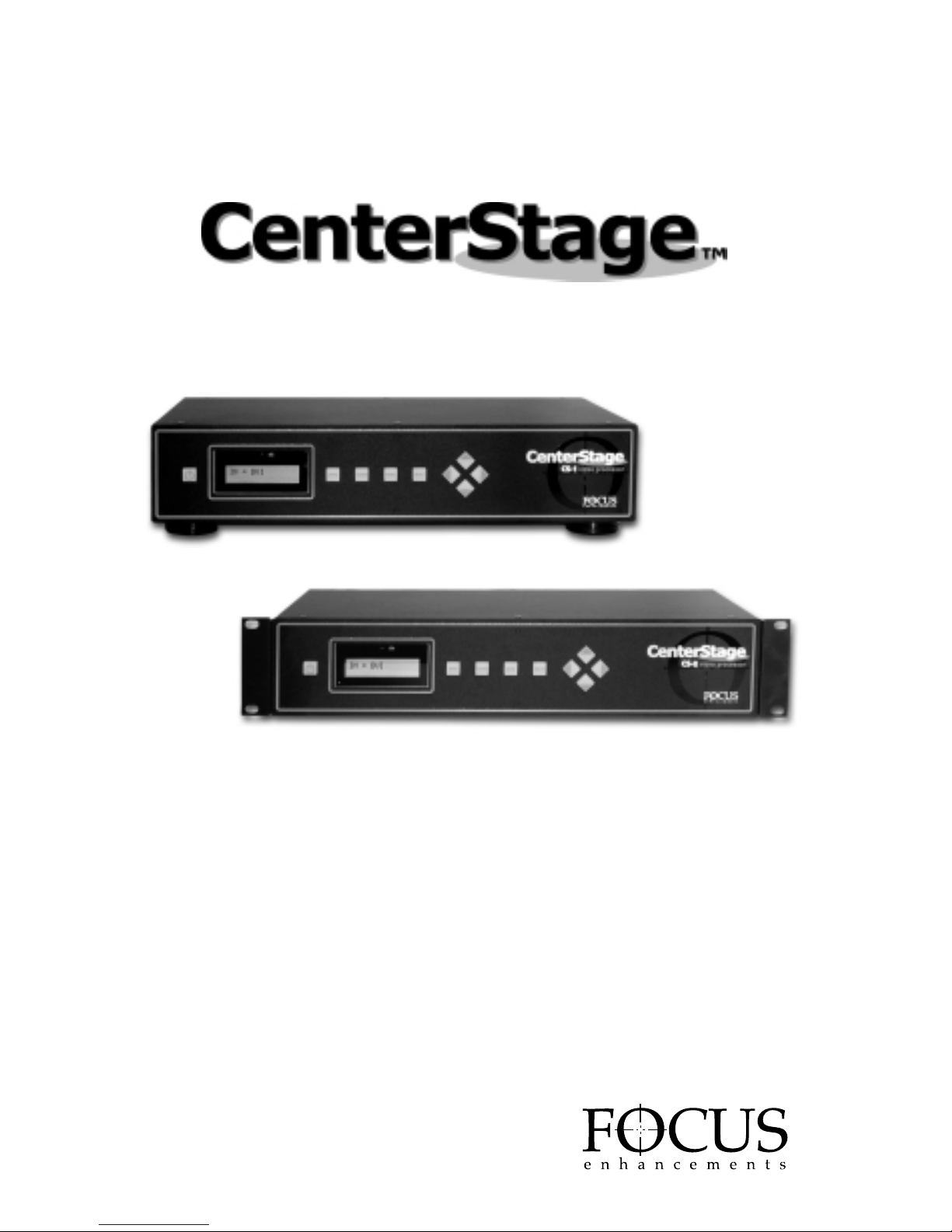
CS-1 and CS-2
Professional Video Processors
USER GUIDE
Version 2.0
MANL-0882-02
Page 2
Please read through these operating instructions so you will know how to operate your model
properly. After you have finished reading the instructions, put them away in a safe place for
future reference.
WARNING:TO PREVENT FIRE OR
SHOCK HAZARD, DO NOT EXPOSE
THIS APPLIANCE TO RAIN OR
MOISTURE.
IMPORTANT NOTICE
(For U.S.Model)
The serial number for this equipment is located
on the bottom of the unit. Please write this serial
number on your enclosed warranty card and
keep it in a secure area. This is for your security.
CAUTION:
This product satisf ies FCC regulations when
shielded cables and connectors are used to
connect the unit to other equipment. To prevent
electromagnetic interference with electric
appliances such as radios and televisions, use
shielded cables and connectors for connections.
NOTE:
This equipment has been tested and found
to comply with the limits for a Class B
digital device, pursuant to Part 15 of the
FCC Rules. These limits are designed to
provide reasonable protection against harmful
interference in a residential installation.
This equipment generates, uses, and can
radiate radio frequency energy and, if not
installed and used in accordance with the
instructions, may cause harmful interference
to radio communications. However, there is
no guarantee that interference will not
occur in a particular installation. If this
equipment does cause harmful interference
to radio or television reception,which can
be determined by turning the equipment off
and on, the user is encouraged to try to
correct the interference by one or more
of the following measures:
• Reorient or relocate the receiving
antenna.
• Increase the separation between the
equipment and receiver.
• Connect the equipment into an outlet
on a circuit different from that to
which the receiver is connected.
• Consult the dealer or an experienced
radio/TV technician for help.
INFORMATION TO USER
Alteration or modif ications car ried out
without appropriate authorization may
invalidate the user’s right to operate
the equipment.
CAUTION:
• Use of controls or adjustments or
performance of procedures other than
those specif ied herein may result in
hazardous radiation exposure.
• The use of optical instruments with
this product will increase eye hazard.
THE STANDBY/ON BUTTON IS
SECONDARY CONNECTED AND
THEREFORE DOES NOT SEPARATE
THE UNIT FROM MAINS POWER
IN STANDBY POSITION.
CAUTION:TO PREVENT ELECTRIC
SHOCK, DO NOT USE THIS (POLARIZED)
PLUG WITH AN EXTENSION CORD,
RECEPTACLE OR OTHER OUTLET UNLESS
THE BLADES CAN BE FULLY INSERTED
TO PREVENT BLADE EXPOSURE.
ATTENTION: POUR PREVENIR LES
CHOCS ELECTRIQUES NE PAS UTILISER
CETTE FICHE POLARISEE AVEC UN
PROLONGATEUR, UNE PRISE DE COURANT
OU UNE AUTRE SORTIE DE COURANT,
SAUF SI LES LAMES PEUVENT ETRE
INSEREES A FOND SANS EN LAISSER
AUCUNE PARTIE A DECOUVERT.
PAGE 2
CenterStage
Page 3
CenterStage
IMPORTANT
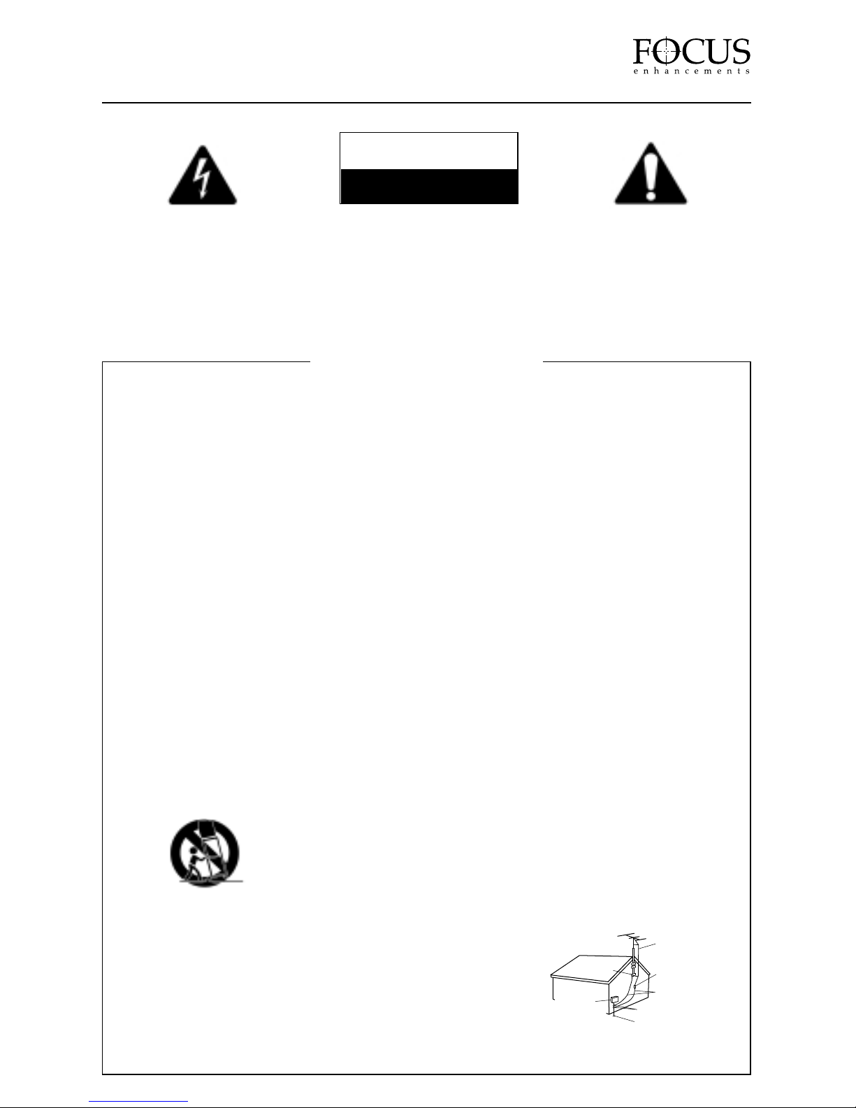
The lightning flash with arrowhead
symbol, within an equilateral triangle,
is intended to alert the user to the
presence of uninsulated “dangerous
voltage ” within the product’s
enclosure that may be of sufficient
magnitude to constitute a risk of
electric shock to persons.
CAUTION:
TO PREVENT THE RISK OF
ELECTRIC SHOCK, DO NOT
REMOVE COVER (OR BACK).
NO USER SERVICEABLE PARTS
INSIDE.REFER SERVICING TO
QUALIFIED SERVICE PERSONNEL.
The exclamation point within an
equilateral triangle is intended to alert
the user to the presence of important
operating and maintenance (servicing)
instructions in the literature accompanying
the appliance.
READ INSTRUCTIONS – All the safety and
operating instructions should be read before the
product is operated.
RETAIN INSTRUCTIONS – The safety and
operating instructions should be retained for
future reference.
HEED WARNINGS – All warnings on the product
and in the operating instructions should be
adhered to.
FOLLOW INSTRUCTIONS – All operating and use
instructions should be followed.
CLEANING – Unplug this product from the wall
outlet before cleaning. The product should be
cleaned only with a polishing cloth or a soft dry
cloth. Never clean with furniture wax, benzine,
insecticides or other volatile liquids since they
may corrode the cabinet.
ATTACHMENTS – Do not use attachments not
recommended by the product manufacturer as
they may cause hazards.
WATER AND MOISTURE– Do not use this
product near water – for example, near a bathtub,
wash bowl, kitchen sink, or laundry tub; in a wet
basement; or near a swimming pool; and the like.
ACCESSORIES – Do not place this product on an
unstable cart, stand, tripod, bracket or table. The
product may fall, causing serious injury to a child
or an adult, and serious damage to the product.
Use only with a cart, stand, tripod, bracket or
table recommended by the manufacturer, or sold
with the product. Any mounting of the product
should follow the manufacturer’s instructions, and
should use a mounting accessory recommended
by the manufacturer.
CART – A product and cart combination should be
moved with care. Quick stops, excessive force,
and uneven surfaces may cause the product and
cart combination to overturn.
VENTILATION – Slots and openings in the cabinet
are provided for ventilation and to ensure reliable
operation of the product and to protect it from
overheating, and these openings must not be
blocked or covered. The openings should never be
blocked by placing the product on a bed, sofa, rug,
or other similar surface. This product should not be
placed in a built-in installation such as a bookcase
or rack unless proper ventilation is provided or the
manufacturer’s instructions have been adhered to.
POWER SOURCES – This product should be
operated only form the type of power source
indicated on the marking label. If you are not sure of
the type of power supply to your home, consult
your dealer or local power company.
LOCATION – The appliance should be installed in
a stable location.
NON-USE PERIODS – The power cord of the
appliance should be unplugged from the outlet
when left unused for a long period of time.
GROUNDING OR
POLARIZATION–
• If this product is equipped with a polarized
alternating current line plug ( a plug having one
blade wider than the other), it will fit into the
outlet only one way. This is a safety feature. If
you are unable to insert the plug fully into the
outlet, try reversing the plug. If the plug should
still fail to fit, contact your electrician to replace
your obsolete outlet. Do not defeat the safety
purpose of the polarized plug.
• If this product is equipped with a three-wire
grounding type plug, a plug having a third
(grounding) pin, it will only fit into a grounding
type power outlet. This is a safety feature. If you
are unable to insert the plug into the outlet,
contact your electrician to replace your obsolete
outlet. Do not defeat the safety purpose of the
grounding type plug.
POWER-CORD PROTECTION – Power supply cords
should be routed so that they are not likely to be
walked on or pinched by items placed upon or
against them, paying particular attention to cords at
plugs, convenience receptacles, and the point where
they exit the product.
OUTDOOR ANTENNA GROUNDING – If an outside
antenna or cable system is connected to the
product, be sure the antenna or cable system is
grounded so as to provide some protection against
voltage surges and built-up static charges. Article
810 of the National Electric Code, ANSI/NFPA 70,
provides information with regard to proper
grounding of the mast and supporting structure,
grounding of the lead-in wire to an antenna
discharge unit, size of grounding connectors,
location of antenna discharge unit, connection to
grounding electrodes, and requirements for the
grounding electrode. See Fig. A.
LIGHTNING – For added protection for this product
during a lightning storm, or when it is left unattended
and unused for long periods of time, unplug it from
the wall outlet and disconnect the antenna or cable
system. This will prevent damage to the product due
to lightning and power-line surges.
POWER LINES – An outside antenna system
should not be located in the vicinity of overhead
power lines or other electric light or power
circuits, or where it can fall into such power lines
or circuits. When installing an outside antenna
system, extreme care should be taken to keep
from touching such power lines or circuits as
contact with them might be fatal.
OVERLOADING – Do not overload wall outlets,
extension cords, or integral convenience
receptacles as this can result in a risk of fire or
electric shock.
OBJECT AND LIQUID ENTRY – Never push
objects of any kind into this product through
openings as they may touch dangerous voltage
points or short-out parts that could result in a fire
or electric shock. Never spill liquid of any kind on
the product.
SERVICING – Do not attempt to service this
product yourself as opening or removing covers
may expose you to dangerous voltage or other
hazards. Refer all servicing to qualified service
personnel.
DAMAGE REQUIRING SERVICE – Unplug this
product from the wall outlet and refer servicing to
qualified service personnel under the following
conditions:
• When the power-supply cord or plug is damaged.
• If liquid has been spilled, or objects have fallen
into the product.
• If the product has been exposed to rain or water.
• If the product does not operate normally by
following the operating instructions. Adjust
only those controls that are covered by the
operating instructions as an improper
adjustment of other controls may result in
damage and will often require extensive work
by a qualified technician to restore the product
to its normal operation.
• If the product has been dropped or damaged in
any way.
• When the product exhibits a distinct change in
performance – this indicates a need for service.
REPLACEMENT PARTS – When replacement parts
are required, be sure the service technician has
used replacement parts specified by the
manufacturer or have the same characteristics as
the original part. Unauthorized substitutions may
result in fire, electric shock or other hazards.
SAFETY CHECK – Upon completion of any service
or repairs to this product, ask the service
technician to perform safety checks to determine
that the product is in proper operating condition.
WALL OR CEILING MOUNT – The product should
not be mounted to a wall or ceiling.
HEAT – The product should be situated away from
heat sources such as radiators, heat, registers,
stoves or other products (including amplifiers)
that produce heat.
ELECTRIC
SERVICE
EQUIPMENT
GROUND
CLAMP
ANTENNA
LEAD IN WIRE
ANTENNA
DISCHARGE UNIT
(NEC SECTION 810-20)
GROUNDING CONDUCTORS
(NEC SECTION 810-21)
NEC — NATIONAL ELECTRICAL CODE
GROUND CLAMPS
POWER SERVICE GROUNDING
ELECTRODE SYSTEM
(NEC ART 250. PART H)
Fig A
CAUTION
RISK OF ELECTRIC SHOCK
DO NOT OPEN
IMPORTANT SAFETY INSTRUCTIONS
Page 4

Table of Contents PAGE
War ning and Safety Infor mation . . . . . . . . . . . . . . . . . . . . . . . . . . . . . . . . . . . . . . . . . . . . . . . .2
Statement of Compliance . . . . . . . . . . . . . . . . . . . . . . . . . . . . . . . . . . . . . . . . . . . . . . . . . . . . .5
Statement of Warranty . . . . . . . . . . . . . . . . . . . . . . . . . . . . . . . . . . . . . . . . . . . . . . . . . . . . . . . .6
Introduction &Setup 7
Introduction . . . . . . . . . . . . . . . . . . . . . . . . . . . . . . . . . . . . . . . . . . . . . . . . . . . . . . . . . . . . . . . .7
Unpacking &Inventory . . . . . . . . . . . . . . . . . . . . . . . . . . . . . . . . . . . . . . . . . . . . . . . . . . . . . . .7
Front Panel . . . . . . . . . . . . . . . . . . . . . . . . . . . . . . . . . . . . . . . . . . . . . . . . . . . . . . . . . . . . . . . .8
Rear Panel . . . . . . . . . . . . . . . . . . . . . . . . . . . . . . . . . . . . . . . . . . . . . . . . . . . . . . . . . . . . . . . . .9
Remote Control . . . . . . . . . . . . . . . . . . . . . . . . . . . . . . . . . . . . . . . . . . . . . . . . . . . . . . . . . . . .10
Typical Conf iguration . . . . . . . . . . . . . . . . . . . . . . . . . . . . . . . . . . . . . . . . . . . . . . . . . . . . . . .11
Setting Up CenterStage 12
Connecting Input Devices . . . . . . . . . . . . . . . . . . . . . . . . . . . . . . . . . . . . . . . . . . . . . . . . . . . .12
Connecting To Display Devices . . . . . . . . . . . . . . . . . . . . . . . . . . . . . . . . . . . . . . . . . . . . . . . .14
Powering Up CenterStage,Input and Output Devices . . . . . . . . . . . . . . . . . . . . . . . . . . . . . . . .14
Selecting An Input Source . . . . . . . . . . . . . . . . . . . . . . . . . . . . . . . . . . . . . . . . . . . . . . . . . . . .15
Selecting An Output Resolution . . . . . . . . . . . . . . . . . . . . . . . . . . . . . . . . . . . . . . . . . . . . . . . .16
The Main Men 17
Navigating the Main Menu . . . . . . . . . . . . . . . . . . . . . . . . . . . . . . . . . . . . . . . . . . . . . . . . . . .17
Picture Settings Menu . . . . . . . . . . . . . . . . . . . . . . . . . . . . . . . . . . . . . . . . . . . . . . . . . . . . . . .18
Output Selection Menu . . . . . . . . . . . . . . . . . . . . . . . . . . . . . . . . . . . . . . . . . . . . . . . . . . . . . .19
Input Selections Menu . . . . . . . . . . . . . . . . . . . . . . . . . . . . . . . . . . . . . . . . . . . . . . . . . . . . . .20
Miscellaneous Menu . . . . . . . . . . . . . . . . . . . . . . . . . . . . . . . . . . . . . . . . . . . . . . . . . . . . . . . .20
Control and Remote 21
Controlling CenterStage from an External Device . . . . . . . . . . . . . . . . . . . . . . . . . . . . . . . . .21
Updating System Software . . . . . . . . . . . . . . . . . . . . . . . . . . . . . . . . . . . . . . . . . . . . . . . . . . .21
Controlling CenterStage Using the CenterStage Remote Software . . . . . . . . . . . . . . . . . . . . . .24
About DVI and HDCP 28
Technical Specifications 29
APPENDIX A:RS-232 Control Protocol 30
APPENDIX B:Input Aspect Ratio to Output Aspect Ratio Primer 32
Notes 33
PAGE 4
CenterStage
Page 5
PAGE 5
CenterStage
Page 6

FOCUS Enhancements, Inc. warrants
this product against defects in materials
or workmanship as follows:
For a period of TWO years from the date
of purchase, FOCUS Enhancements, Inc.
will repair or replace the unit, at our option,
without charge for parts or labor. After the
period of TWO years, you must pay all
parts and labor charges.
The limited warranty is extended only to
the original purchaser and is valid only to
consumers in the United States and Canada.
It does not cover damage or failure caused
by or attributable to Acts of God, abuse,
misuse, improper or abnormal usage, faulty
installation, improper maintenance, lightning,
or other incidences of excessive voltage, or
any repairs or tampering by other than a
FOCUS Enhancements authorized repair
facility. It does not cover replacement
of batteries or other consumable parts,
transportation costs or damage in transit.
This warranty will become void if the serial
number or model number identif ication has
been wholly or partially removed or erased.
Repair or replacement under the terms of
this warranty do not extend the terms of this
warranty. This warranty can not be modif ied
by an agent of FOCUS Enhancements, Inc.
unless in written and signed by an officer
of FOCUS Enhancements, Inc.
Should this product prove defective in
workmanship or material, the consumer’s
sole remedies shall be such repair or
replacement provided by the terms of
this warranty. Under no circumstances shall
FOCUS Enhancements, Inc. be liable for
any loss or damage, direct, consequential, or
incidental, arising out of the use of or inability
to use this product. Some states do not allow
limitations on how long an implied warranty
lasts or the exclusions or limitations of
incidental or consequential damages, so the
above limitations or exclusions may not apply
to you. This warranty gives you specific legal
rights. You may also have other rights which
vary from state to state.
For customers outside the USA or Canada,
please contact your dealer or distributor for
repairs or technical support.
In the United States or Canada, to obtain
warranty service, call or write the FOCUS
Enhancements, Inc. Technical Support Line
for a Return Material Authorization (RMA)
number. Technical Support can be reached at:
Email: support@FOCUSinfo. com
Telephone: 408-370-9963. 8AM-5PM,
Monday to Friday (PST)
(Hint: Mondays tend to be the busiest)
Fax: 408-866-4859
Address: FOCUS Enhancements, Inc.
1370 Dell Ave.
Campbell, CA. 95008
Please mark the RMA number clearly on
the outside of the package. Include a copy
of your sales receipt, a brief description of the
symptoms, your name, address, phone number
and any special shipping instructions. Then
deliver or ship the product, postage and shipping
costs prepaid, to a FOCUS Enhancements
authorized repair facility. For the name of
the nearest repair facility, contact FOCUS
Enhancements, Inc. Technical Support.
PAGE 6
CenterStage
Page 7

INTRODUCTION & SETUP
Introduction
Thank you for purchasing the CenterStage Video Processor from FOCUS Enhancements.
CenterStage offers exceptional image quality, flexibility, and the latest de-interlacing digital
video processing and scaling technology.
The purpose of this User Guide is to describe the various capabilities, specifications and other
information about your CenterStage unit. For additional information or technical support, please
contact your FOCUS Enhancements distributor or dealer. If you are in the US or Canada, you
can contact FOCUS Enhancements directly at:
Technical Support
Email: [email protected]
WWW: http://www.focusinfo.com/support/
Telephone: 408-370-9963. 8AM-5PM, Monday to Friday (PST)
(Hint: Mondays tend to be the busiest)
Fax: 408-866-4859
Unpacking & Inventory
Remove your CenterStage unit from its shipping container. You should have the following items
included with the unit:
• CenterStage unit
• User Guide
• IEC Power Cord
• VGA pass-thru cable (HD15M – HD15F)
• Infrared Remote Control and Batteries
• Warranty Card and Limited Warranty Statement
Please ensure all these items are included. Inspect the CenterStage unit for any signs of shipping
damage. It’s advised that you keep all shipping materials if the unit is to be moved or returned for
service at a later date.
PAGE 7
CenterStage
Page 8
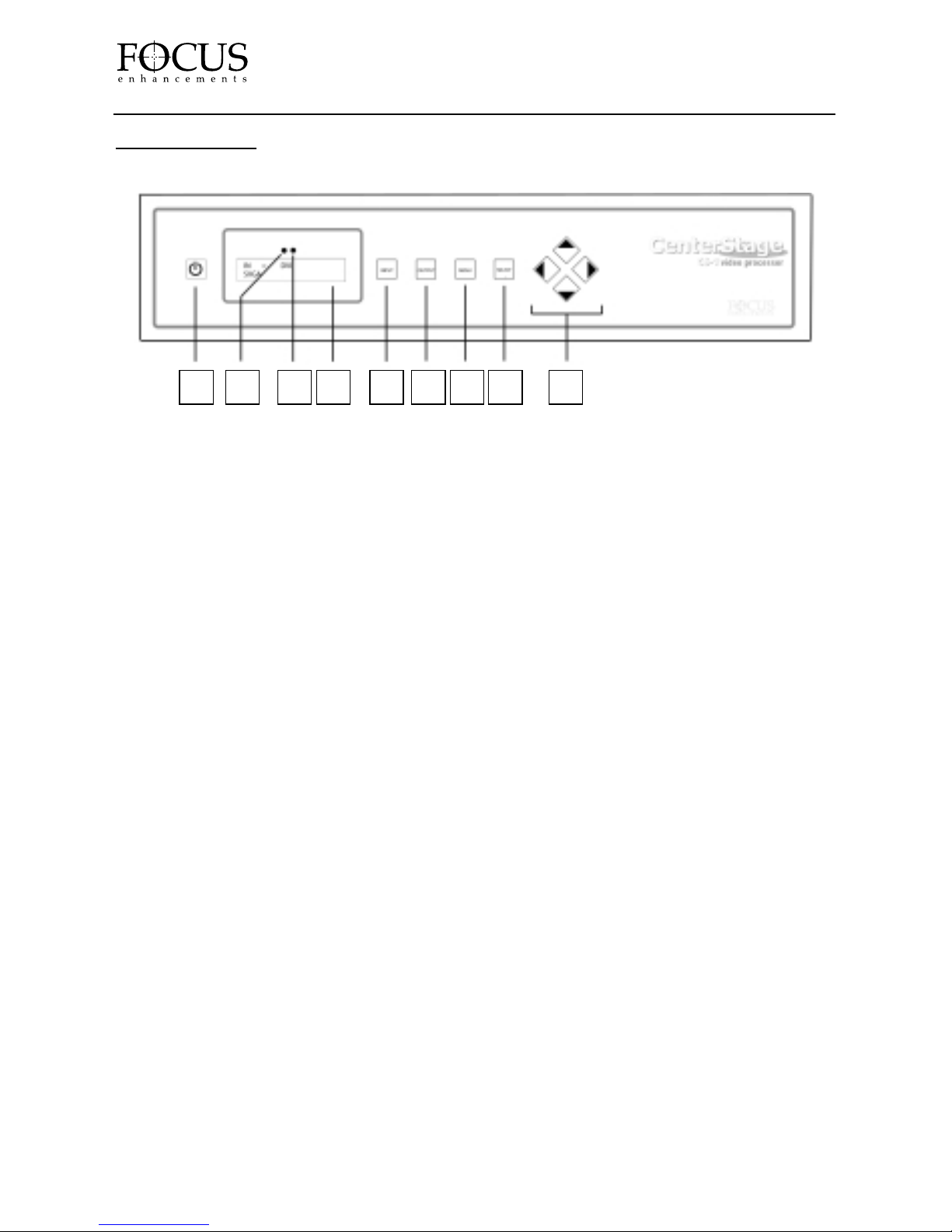
FRONT PANEL
1. POWER
This button powers the CenterStage unit
ON and OFF. The On/Off power switch on
the rear panel of CenterStage must be in the
ON position for the front panel power switch
to work.
2.
INFRARED REMOTE SENSOR
Sensor for CenterStage’s infrared remote
control unit.
3.
AMBIENT LIGHT SENSOR
This sensor detects room ambient light and
changes the brightness of CenterStage’s LCD
and buttons. In dark areas, the CenterStage
LCD and buttons will be dimmer while in
bright areas, they will be brighter.
4.
LCD DISPLAY
The 32-character LCD displays the current
CenterStage input source and output resolution
(ships with a protective cover film, simply
remove before using).
5.
INPUT
Pressing this button cycles through the
available inputs on CenterStage. To execute,
press the SELECT button. If you do not press
the SELECT button, the input will revert to
the previous selection. The current input will
display on the top line of the LCD display.
6.
OUTPUT
Pressing this button cycles through the
available output resolutions on CenterStage.
To execute, press the SELECT button. If you
do not press the SELECT button, the output
will revert to the previous selection. The current
output will display on the bottom line of the
LCD display.
7.
MENU
Pressing this button brings up the CenterStage
Main Menu on the On Screen Display. It is
necessary to have a display device connected
to view this menu.
8.
SELECT
This button is used for selecting various
options within the CenterStage On Screen
Display Menu. It is also used for executing
a new INPUT or OUTPUT selection.
9.
NAVIGATION BUTTONS
This group of buttons allows for navigation
through the various CenterStage menu items.
PAGE 8
CenterStage
1 2 3 4 5 6 7 8 9
Page 9
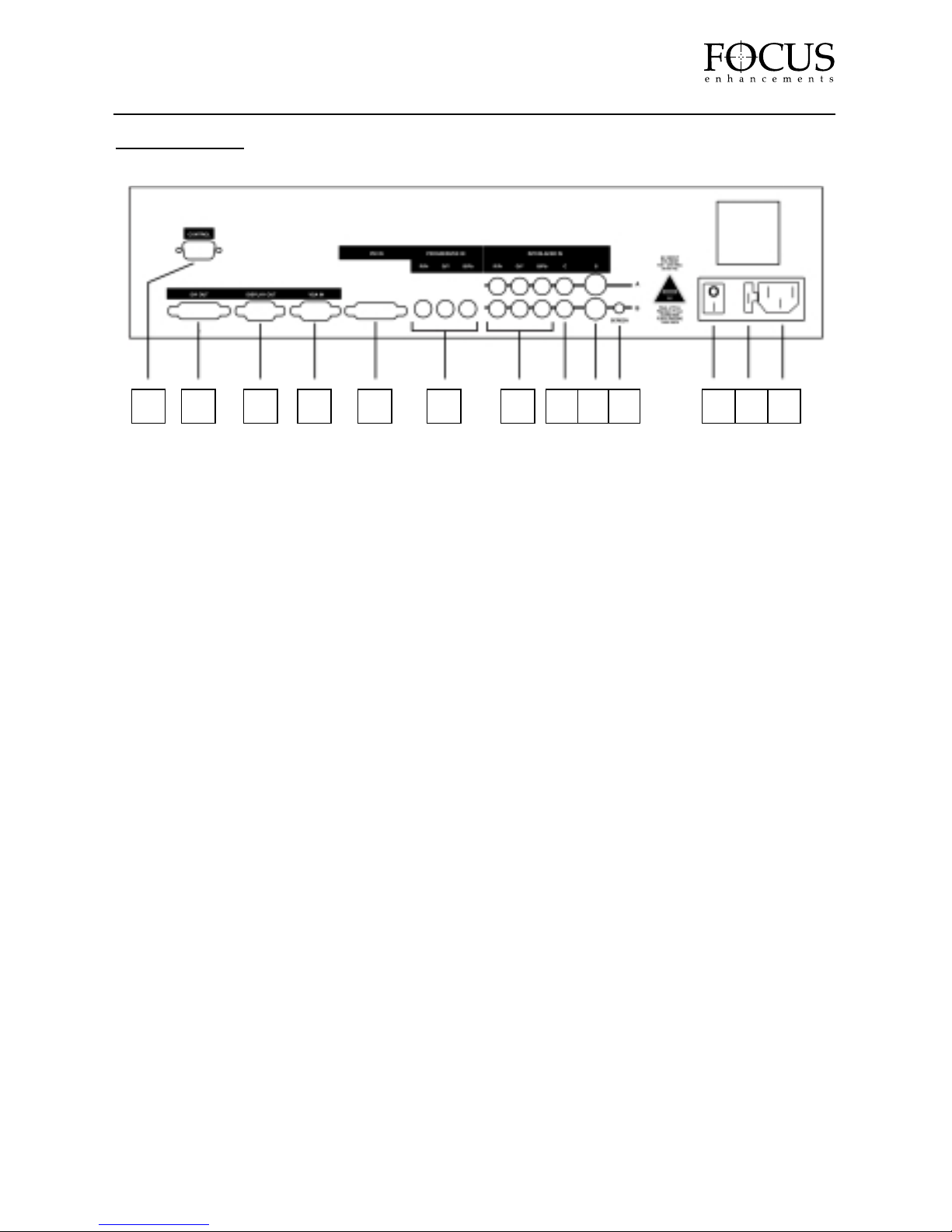
REAR PANEL
1. CONTROL
Standard 9-pin RS-232 port. For connection
of external control equipment and CenterStage
remote software (CSR).
See page 21 for more details.
2. DVI OUT
DVI (Digital Visual Interface) digital
high resolution output.
See page 28 for more details.
3. DISPLAY OUT
HD-15F RGB or component high
resolution output.
4.
VGA IN
HD-15M active buffered VGA or Analog
HDTV pass through.
5.
DVI IN
DVI (Digital Visual Interface) digital input.
See page 28 for more details.
6. PROGRESSIVE IN – R/Pr, G/Y, B/Pb
Progressive RGB or YPrPb input
(RCA on CS1, BNC on CS2).
7.
INTERLACED IN – R/Pr, G/Y, B/Pb
Channel A & B
Interlaced RGB or YPrPb input
(RCA on CS1, BNC on CS2).
8.
INTERLACED IN – C (COMPOSITE)
Channel A & B
Interlaced Composite input
(RCA on CS1, BNC on CS2).
9.
INTERLACED IN – S (S-VIDEO)
Channel A & B
Interlaced S-Video input
(RCA on CS1, BNC on CS2).
10.
SCREEN
Screen Trigger (12V, 3.5mm, 2-pin, Tip=+)
11.
POWER SWITCH
12. FUSE
250V rating, 1.6A slow blow, 5mm x 20mm.
Replace with same fuse only.
13.
IEC POWER CONNECTOR
AC Power Inlet. Use supplied IEC power cable
only. 100-240V AC, Auto Ranging, 50-60Hz
PAGE 9
CenterStage
1 2 3 4 5 6 7 8 9 10 11 12 13
Page 10
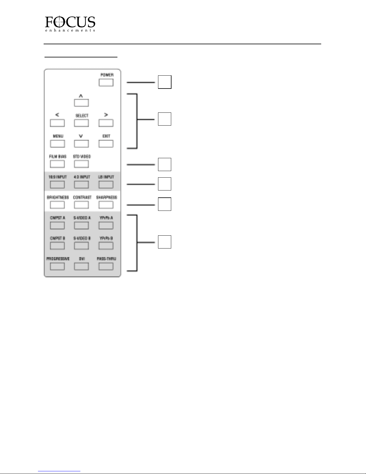
REMOTE CONTROL
1. POWER
CenterStage ON/OFF Button.
2.
ON SCREEN DISPLAY CONTROL
This bank of buttons features control for
the CenterStage On Screen Display (OSD).
Pressing MENU launches the OSD, EXIT
will exit the particular menu item or the OSD
itself, SELECT is used to choose various
options in the menus and the arrow keys are
used for navigation.
3.
FILM/VIDEO SELECT
This bank of buttons is used for selecting
either FILM BIAS or STANDARD VIDEO
DSP settings for the output.
4.
INPUT ASPECT RA TIO
This bank of buttons allows selection of
the input aspect ratio. Choose from 16:9,
4:3 or LB (Letterbox, 4:3 or 16:9).
5.
PICTURE SETTINGS
This bank of buttons allows for adjustment of
the output image. It will launch CenterStage’s
OSD to adjust either BRIGHTNESS,
CONTRAST or SHARPNESS.
6.
INPUT SELECTION
This bank of buttons allows selection of
CenterStage input sources. Choose from
Composite Ch. A, Composite Ch. B, S-Video
Ch. A, S-Video Ch. B, YPrPb (Component)
Ch. A, YPrPb (Component) Ch. B, Progressive
(RGB or Component), DVI and VGA Pass
Thru. Upon selection, CenterStage will
immediately change to that selected input
source. It is not necessary to press SELECT
once you have chosen an input on the remote.
PAGE 10
CenterStage
1
2
3
4
5
6
Page 11
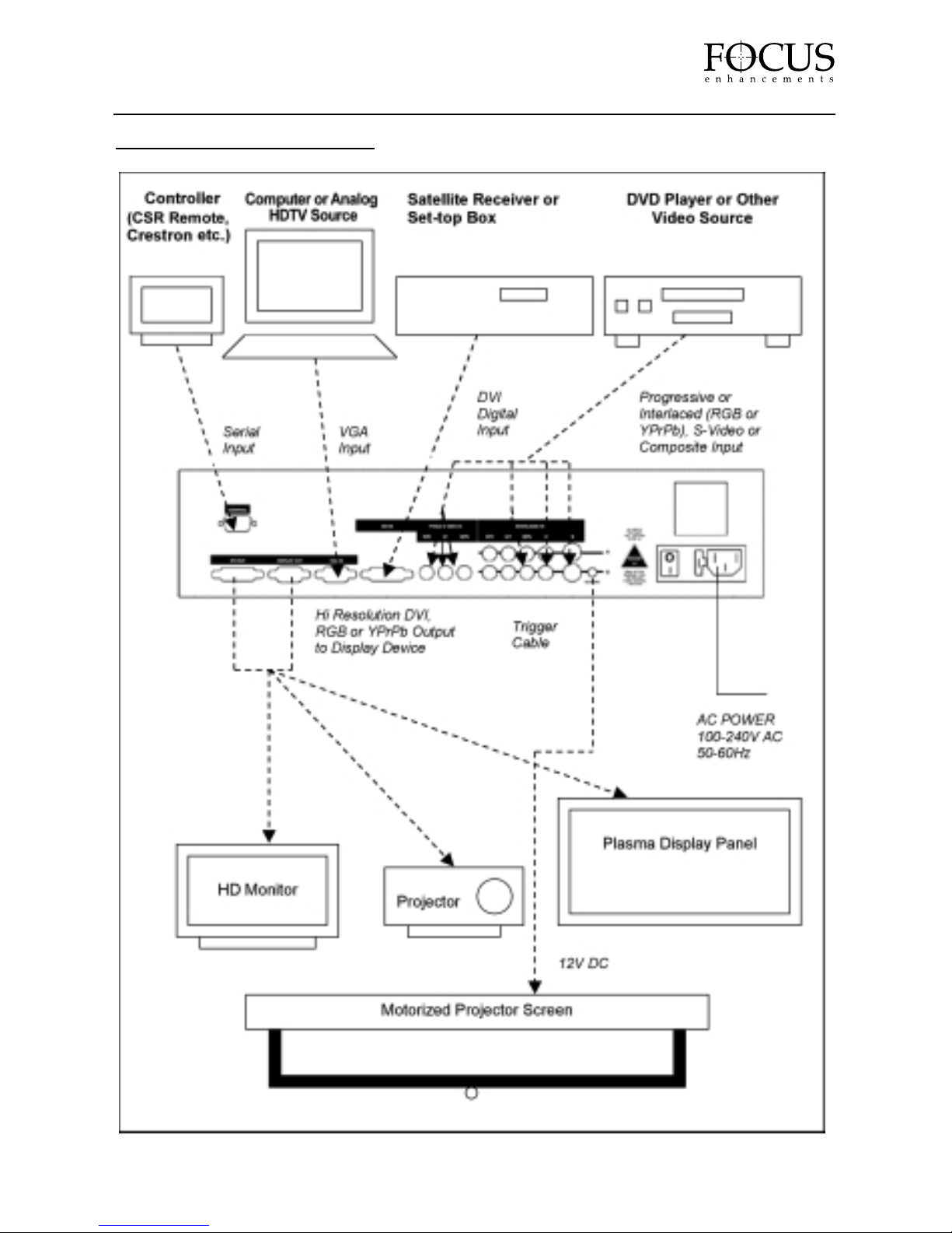
TYPICAL CONFIGURATION
PAGE 11
CenterStage
Page 12

SETTING UP CENTERSTAGE
Once you have unpacked your CenterStage unit and have become familiar with the front and back
panel and remote features, install the CenterStage unit where it will be used. Study the TYPICAL
CONFIGURATION from the previous page and identify which input sources as well as which
output displays you intend to use with your CenterStage video processor. You may need to consult
your input and display device manuals for precise specifications. Make sure you have these
available before attempting to connect anything.
Connecting Input Devices
Once you have identified the input devices you intend to use, connect these devices to
CenterStage. It is possible to connect nine devices to CenterStage. Be aware that while devices
may have similar connectors, the output standard may differ from one unit to another. Consult
your input devices’specifications for more information. Your input choices are:
CenterStage CS-1
Input Connector Standard Input Device Example
VGA HD-15M VESA or HDTV Computer, HDTV Analog
DVI DVI-D Male DVI-D Set Top Box*, DVD Player*,
Computer
Progressive 3 x RCA RGB or YPrPb Progressive Output DVD Player
2 x Interlaced 3 x RCA RGB or YPrPb DVD Player
RGB/YPrPb
2 x Interlaced RCA Composite Set Top Box, Cable Box,
Composite Satellite
2 x Interlaced 4- pin mini DIN S-Video (Y/C) Set Top Box, Cable Box, S-Video
S-Video Satellite Receiver, DVD Player
PAGE 12
CenterStage
Page 13

CenterStage CS-2
Input Connector Standard Input Device Example
VGA HD-15M VESA or HDTV Computer, HDTV Analog
DVI DVI-D Male DVI-D Set Top Box, DVD Player,
Computer
Progressive 3 x BNC RGB or YPrPb Progressive Output DVD Player
2 x Interlaced 3 x BNC RGB or YPrPb DVD Player
RGB/YPrPb
2 x Interlaced BNC Composite Set Top Box, Cable Box,
Composite Satellite Receiver, VCR
2 x Interlaced 4- pin mini DIN S-Video (Y/C) Set Top Box, Cable Box, S-Video
S-Video Satellite Receiver, DVD Player, VCR
* Your DVI input device may feature HDCP copy protection. The CenterStage CS-1 features
optional HDCP compatibility while it is standard on CenterStage CS-2. For more information, see
page 28 of this User Guide.
NOTE: The CenterStage CS-2 features a Time Base Corrector to accept VCR and other unstable
input sources. If you wish to use these sources, ideally you will need a CS-2 model
PAGE 13
CenterStage
Page 14
CONNECTING TO DISPLAY DEVICES
Once you have connected your desired input devices you can now connect your display device.
Be aware that while devices may have similar connectors, the output standard may differ from one
unit to another. While it is possible to connect two display devices to CenterStage, we recommend
that only one be connected at a time. This is due to the fact that output settings are global and settings
for one display may not match that of another. The two outputs available on CenterStage are:
CenterStage CS-1 and CS-2
Output Connector Standard Output Device Example
DISPLAY OUT HD-15F Analog Projector, HD Monitor, Plasma Display,
RGB or YPrPb Computer Monitor.
DVI OUT DVI-I Female DVI-I DVI enabled Plasma
Display, HD Monitor or Computer Monitor
Powering Up CenterStage, Input and Output Devices
Once you have connected all desired input devices and your display device, power up each of the
input devices followed by the display device. If you are unsure how to do this, consult your input
or display device instruction manual.
Once all your input devices and display are powered up, you can power up the CenterStage unit.
First check that you have connected the supplied IEC power cable and then turn on the Main
Power Switch on the rear of the unit (see page 9 for more details). Then you can either turn on
CenterStage by pressing the “POWER” button on the supplied remote control or by pressing the
(POWER) button on the front panel of the unit. The LCD display and buttons will light
up green.
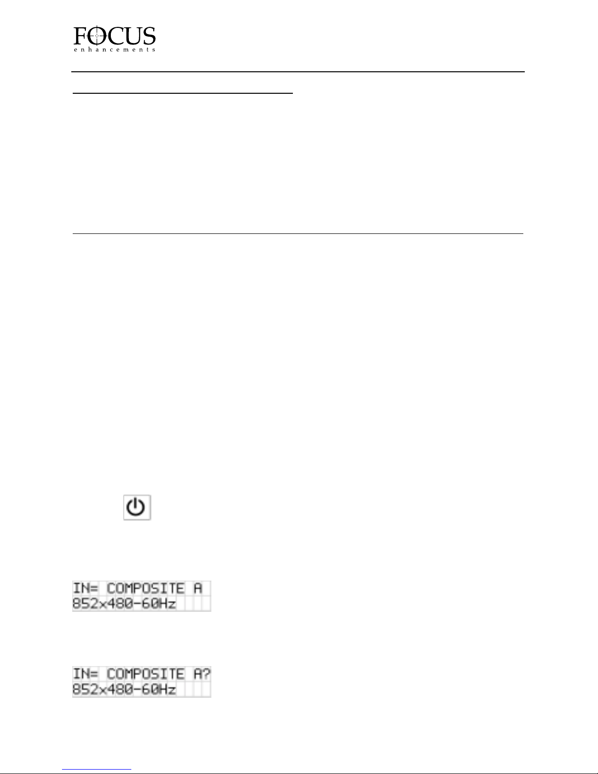
If you have a video source connected to the “Composite Channel A” input on CenterStage, you
will see the following LCD display:
If no video source is connected to “Composite Channel A” on CenterStage, you will see the
following LCD display:
PAGE 14
CenterStage
Page 15

SELECTING AN INPUT SOURCE
Once you have powered up your CenterStage unit and sources, it is possible to select the desired
input source. This is done by pressing CenterStage ’s (INPUT) button. By pressing this
button, CenterStage will cycle through the available inputs. To execute a selection, press the
(SELECT) button. If SELECT is not pressed, the CenterStage will revert to the previous
selection. It is also possible to select an input directly using the CenterStage remote control unit
(It is not necessary to press SELECT on the remote). These will display on the top line
of the CenterStage LCD display.
Available inputs for CenterStage CS-1 and CS-2 are:
INPUT NAME INPUT
COMPOSITE A Composite Channel A
COMPOSITE B Composite Channel B
S-VIDEO A S-Video Channel A
S-VIDEO B S-Video Channel B
YPrPb A YUV (Y,Pr,Pb) Channel A
YPrPb B YUV (Y,Pr,Pb) Channel B
RGB A RGB Channel A
RGB B RGB Channel B
PROG. RGB Progressive RGB
PROG. YPrPb Progressive Component (Y,Pr,Pb)
DVI Digital Video Interface
VGA PASS VGA (Computer) Active Pass-Thru
If a video input is detected on the selected input, CenterStage will display the output resolution
on the bottom line of the LCD display. If no video input is detected, CenterStage will display
a question mark (“ ? ”) next to the input name on the LCD display.
PAGE 15
CenterStage
Page 16

SELECTING AN OUTPUT RESOLUTION
To select an output display resolution, f irst consult the User Guide or specification of your
Display device. Locate the Native Resolution (also may be referred to as Number of Pixels,
Resolution or Native Pixel Resolution).
Once you have located the Native Resolution, press CenterStage’s (OUTPUT) button
to cycle through the available output resolutions. To execute a selection, press the
(SELECT) button. If SELECT is not pressed, the CenterStage will revert to the previous
selection. These will display on the bottom line of the CenterStage LCD display.
The factory set of available output resolutions for CenterStage CS-1 and CS-2 are:
NOTE: You can customize, rename, add or delete resolutions using the CenterStage Remote
Software (see page 24 for more information). The set listed below may not match that of your
CenterStage unit. The list on the following page is the set supplied by the factory.
OUTPUT OUTPUT TYPE ASPECT RATIO COLOR SPACE
852x480-60Hz Plasma 16:9 RGB or Y,Pr,Pb
SVGA–60Hz VESA 4:3 RGB or Y,Pr,Pb
SVGA-72(75)Hz VESA 4:3 RGB or Y,Pr,Pb
XGA-60Hz VESA 4:3 RGB or Y,Pr,Pb
XGA-72(75)Hz VESA 4:3 RGB or Y,Pr,Pb
WXGA-60Hz Plasma 16:9 RGB or Y,Pr,Pb
WXGA-72(75)Hz Plasma 16:9 RGB or Y,Pr,Pb
1280x960-60Hz Plasma 16:9 RGB or Y,Pr,Pb
1024x1024-60Hz Plasma 16:9 RGB or Y,Pr,Pb
1024L-72(75)Hz Plasma 16:9 RGB or Y,Pr,Pb
SXGA-60Hz VESA 4:3 RGB or Y,Pr,Pb
SXGA-72(75)Hz VESA 4:3 RGB or Y,Pr,Pb
D-ILA-60Hz Projector/HDTV 4:3 RGB or Y,Pr,Pb
720p Projector/HDTV/Plasma 16:9 Y,Pr,Pb
1080i Projector/HDTV 16:9 Y,Pr,Pb
1080p Projector/HDTV 16:9 Y,Pr,Pb
Your display may work with several resolutions. It also may require some adjustment on the
display itself in order to size the picture etc. It is recommended that you adjust your display
device first before adjusting/fine tuning with CenterStage.
PAGE 16
CenterStage
Page 17
THE MAIN MENU
It is possible to change picture settings, output selections, picture size and position, input selections
as well as other settings using the CenterStage Main Menu. The Main Menu appears on the
CenterStage On Screen Display (OSD). To activate the Main Menu, you must have CenterStage
connected to an appropriate display device and it is also a good idea to use a setup DVD such as
Video Essentials - Optimizing Your Audio/Video System or the AVIA Guide to Home Theater. These
will assist greatly in achieving a good image.
Navigating the Main Menu
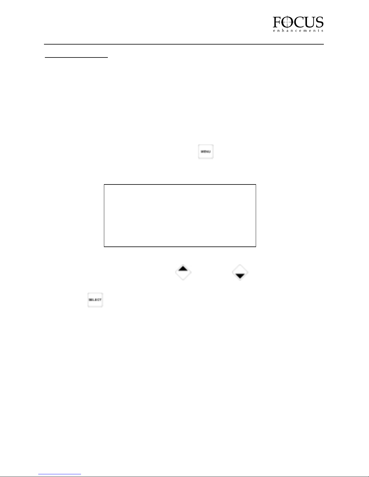
To bring up the CenterStage OSD, press the (MENU) button. It is also possible
to launch the Main Menu by pressing the MENU button on the remote control unit.
The following should appear on your display device:
To navigate through the menu, press the (UP) and (DOWN) buttons on the
CenterStage front panel (you can also use the remote control). To select a par ticular menu, press
the (SELECT) button. The selected menu will appear on the On Screen Display.
PAGE 17
CenterStage
MAIN MENU
Picture Settings
Output Selections
Input Selections
Miscellaneous
Page 18

Picture Settings Menu
In the PICTURE SETTINGS menu, it is possible to change input source:
BRIGHTNESS: Values are adjustable between –50 and +50.
CONTRAST: Values are adjustable between –50 and +50.
SHARPNESS: Value is adjustable between –50 and +50.
SATURATION: Also known as Color Saturation. Values are adjustable between –50 and +50.
HUE: Value is adjustable between –50 and +50.
RESET: Selecting this option will return all values in PICTURE SETTINGS to the factory
default state (all values reset to 0).
MAIN MENU: Exits to the Main Menu.
In all cases above, the default value will produce internal digital values in accordance with
ITU656 and an analog RGB HI RES out with a full-scale range of 0. 0 to 0. 7V when a 100%
amplitude and a 100% saturation color bar test pattern is applied to the CenterStage composite
input.
PAGE 18
CenterStage
BRIGHTNESS: 0
____________|______________
CONTRAST: 0
____________|______________
SHARPNESS: 0
____________|______________
SATURATION: 0
____________|______________
HUE: 0
____________|______________
[RESET]:
[MAIN MENU]:
Page 19
Output Selection Menu
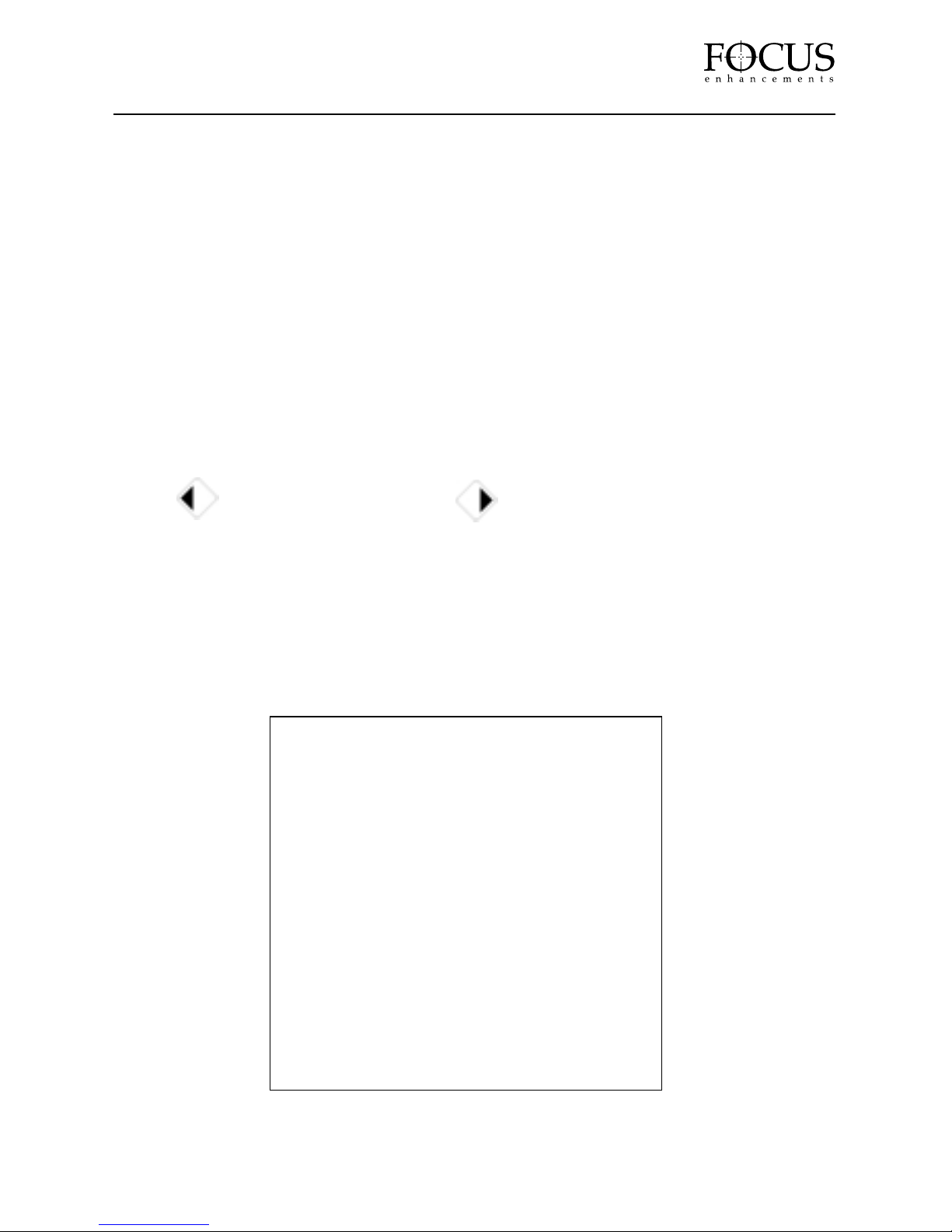
In the OUTPUT SELECTIONS menu, it is possible to change variables relating to the output of
CenterStage. The OUTPUT SELECTIONS menu items are:
RESOLUTION: Identif ies the cur rent output resolution.
OUTPUT ASPECT : Allows selection of either 4:3, 4:3 AL (Anamorphic lens) or 16:9 output
aspect ratio for the selected resolution.
OUTPUT FORMAT: Allows selection of either YPrPb (Component) or RGB output. See your
display devices documentation for more information on which to choose.
REFRESH RATE: Displays the current refresh rate. If a 60Hz Output Resolution is selected, it is
not possible to change this setting. It will display 60Hz. If you select a 72 /75Hz Output
Resolution, it is possible to switch between 72 and 75 Hz.
SYNC ON GREEN: Allows Sync to be switched between G/Y and H/V.
OUTPUT V POSN: Allows you to adjust the vertical position of the output image (use the
(LEFT) button for up and the (RIGHT) button for down). Values are adjustable
between –50 and +50.
OUTPUT H POSN: Allows you to adjust the horizontal position of the output image. Values are
adjustable between –50 and +50
OUTPUT V SIZE: Allows you to adjust the vertical size of the output image (use the (LEFT)
button for up and the (RIGHT) button for down). Values are adjustable between –50 and +50.
OUTPUT H SIZE: Allows you to adjust the horizontal size of the output image. Values are
adjustable between –50 and +50
MAIN MENU: Exits to the Main Menu.
PAGE 19
CenterStage
RESOLUTION 852x480–60Hz
OUTPUT ASPECT: 16:9
OUTPUT FORMAT: RGB
REFRESH RATE: 72Hz
SYNC : G/Y
OUTPUT V POSN: 0
____________|______________
OUTPUT H POSN: 0
____________|______________
OUTPUT V SIZE: 0
____________|______________
OUTPUT H SIZE: 0
____________|______________
[MAIN MENU]
Page 20
Input Selections Menu
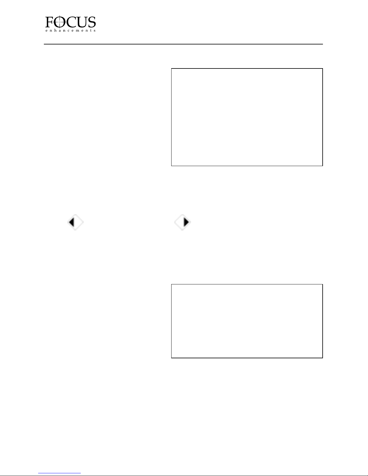
In the INPUT SELECTION menu, it
is possible to change the following:
INPUT SELECT: Allows selection of
a particular input. Changes made only
affect the currently selected input.
INPUT ASPECT : Allows selection
of different input aspect ratios. Choices
include 4:3, 16:9, 4:3 LB (Letterbox) and
16:9 LB (Letterbox).
COLOR STANDARD: Selects color
standard as either NORMAL (NTSC-US
and PAL), NTSC-JAPAN, NTSC-4.43
(PAL 60Hz) and SECAM.
AUTO GAIN: Selects Auto Gain ON or OFF. Auto Gain should be selected ON when viewing off-
air, cable box or satellite program. Auto Gain compensates for changes in luminance from channel
to channel or program to program. For DVD and other high quality sources, select auto gain to OFF.
INPUT V POSN: Allows you to adjust the vertical position of the input image (use the
(LEFT) button for up and the (RIGHT) button for down). Values are adjustable
between –50 and +50.
INPUT H POSN: Allows you to adjust the horizontal position of the input image. Values are
adjustable between –50 and +50
MAIN MENU: Exits to the Main Menu.
Miscellaneous Menu
The MISCELLANEOUS menu allows
for selection of some of the different
modes available in CenterStage. It is
possible to change:
DSP MODE: Selects between FILM
BIAS and STD VIDEO mode. In film
bias mode, the processor is optimized for
f ilm based content on the input. If you
are viewing a program that was originally
produced on f ilm (such as a movie on DVD), select FILM BIAS. For all other sources (such as
television programs, sports, live camera etc.), select STD VIDEO.
RS232 BAUD: Sets RS232 Baud Rate to either 9600 or 57600.
CALIBRATION: Calibrates the progressive inputs. Should be only used once the first time a
progressive input is used.
SPLIT SCREEN: Tur ns Split Screen Mode ON or OFF. Split Screen mode is useful for
demonstration purposes. When Split Screen is ON, the left half of the display is showing normal
CenterStage processing while on the right half, motion compensation is disabled on the input. The
difference is apparent in content that contains lots of movement. Ensure to turn Split Screen to
OFF for normal viewing.
PAGE 20
CenterStage
INPUT SELECT: COMPOSITE A
INPUT ASPECT: 16:9
COLOR STANDARD: NTSC-JAPAN
AUTO GAIN: OFF
INPUT V POSN: 0
____________|______________
INPUT H POSN: 0
____________|______________
[MAIN MENU]
DSP MODE: FILM BIAS
RS232 BAUD: 9600
CALIBRATION: CONFIRM
SPLIT SCREEN: OFF
FACTORY RESET: CONFIRM
Version X. XX Month – Day – Year
[MAIN MENU]
Page 21

FACTORY RESET: Resets CenterStage to the factory default settings. When selected, you will
be prompted with “SURE?”. Pressing select will confir m your selection. THIS IS NOT
REVERSIBLE! ALL VOLATILE SETTINGS WILL BE ERASED!
VERSION NUMBER: Displays the current system software version and its release date.
MAIN MENU: Exits to the Main Menu.
CONTROL & REMOTE
In addition to the controls that are available on the CenterStage front panel and supplied remote
control unit, it is also possible to use an external controller such as a Crestron or AMX/Panja unit.
It is also possible to control CenterStage from a computer using the CenterStage Remote (CSR)
software.
Controlling CenterStage from an External Device
The RS-232 port is located on the CenterStage rear panel. It uses a standard DB-9 Female
connector. From this port it is possible to connect an external controller such as a Crestron,
AMX/Panja or other home automation systems. Consult the FOCUS Enhancements website as
well as the control system manufacturer’s website for more information on current compatibility.
It is necessary to use a standard DB-9 cable in order to connect CenterStage to your controller device.
For more detailed information on using the RS-232 port for control, see Appendix A of this User’s Guide.
Updating System Software
WARNING: UPGRADING SYSTEM SOFTWARE WILL ERASE ALL RESOLUTIONS AND
SETTINGS IN CENTERSTAGE. CREATE A BACKUP IF REQUIRED BEFORE PROCEEDING.
(See “Global Setting” on page on page 26.)
NOTE: Your CenterStage unit was shipped from the factory with the latest version of software at
the time of manufacture. Check the FOCUS Enhancements website regularly for available updates.
It is possible to update the CenterStage system software using the CSR Remote application. In
order to update the system software, you must have a computer with Windows 95/98/Me/NT/2000
and an available serial port. You must also have a standard serial cable (DB-9M to DB-9F).
To identify which version of software you currently have on CenterStage, turn on the CenterStage
OSD and select the Miscellaneous Menu (you will need to be connected to an appropriate display
device). Version Number is displayed at the bottom of the Miscellaneous Menu. The latest version
of software is available for download from:
http://www
. focusinfo. com/products/centerstage/centerstage. htm
You will also need the CenterStage Remote (CSR) application loaded onto a computer to update
your system software. It is also available from the CenterStage website above.
PAGE 21
CenterStage
Page 22
If you have not done so already, install the CSR application on you computer. It can be
downloaded from:
http://www
. focusinfo. com/products/centerstage/centerstage. htm
To install, simply unzip the downloaded file, locate “setup.exe” and click on it to begin the install
procedure. Follow the on screen instr uctions to load the application.
Once installed, do the following:
1. Power up CenterStage and your computer. Using the serial cable, connect the CenterStage
“Control” port on the rear panel to the computer’s serial port. Verify the serial port is operating
correctly and make note which COM port you are using and its Baud Rate.
2. The CenterStage unit must be in prog ramming mode. To do this from the front panel, press
and hold OUTPUT and MENU at the same time. Then press and release INPUT. Then release
OUTPUT and MENU. The CenterStage front panel lights will go out.
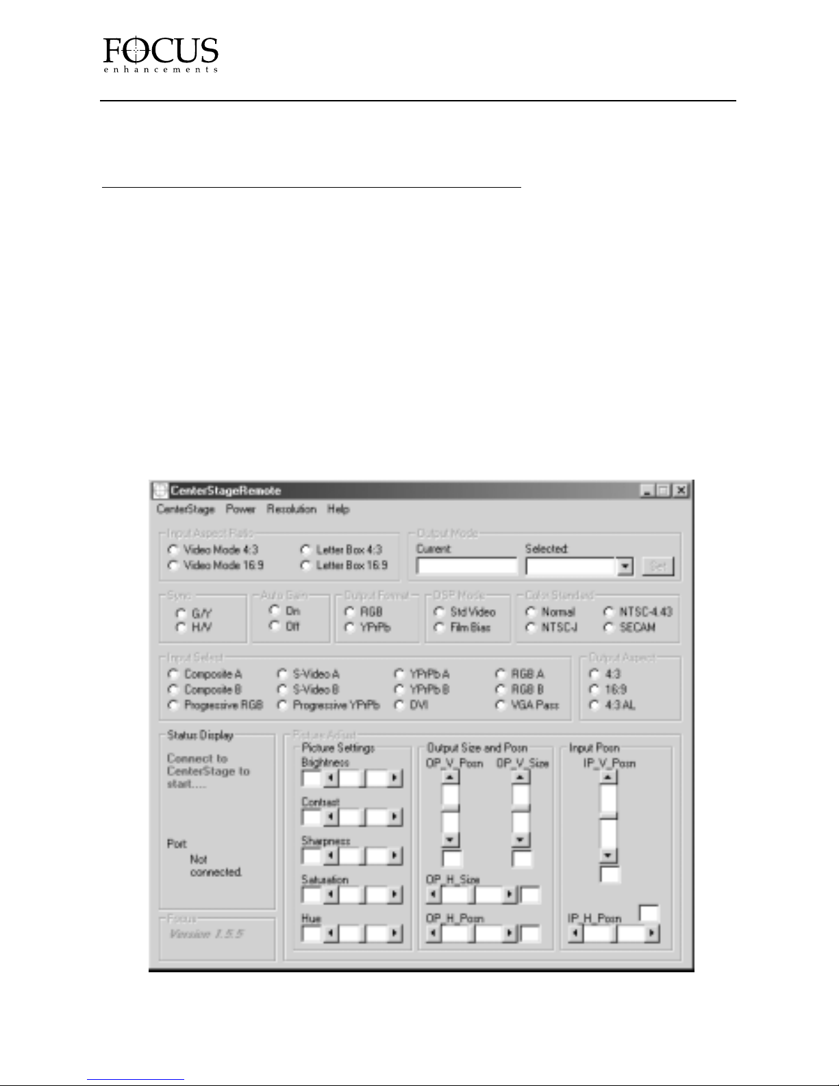
Now launch the CSR Application by selecting Start -> Programs -> CenterStage Remote. The
following screen will appear.
PAGE 22
CenterStage
Page 23
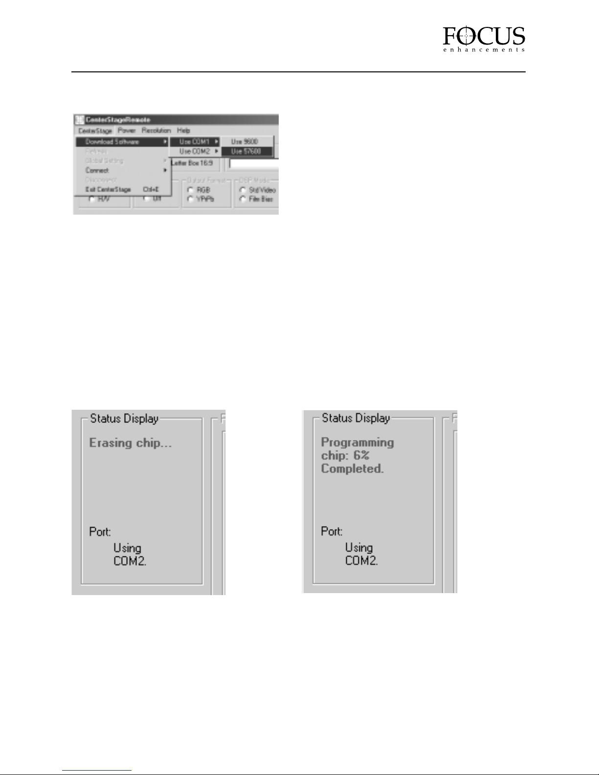
To star t the CenterStage software update, select CenterStage -> Download Software from the
pull-down menu. You will need to select either COM 1 or COM 2. You will also need to know
the baud rate your computer's serial port is set to.
With CenterStage, you can select either 9600 or
57600. Consult your computer's documentation
for more information.
You will be warned to ensure that you have
CenterStage in Programming Mode. Press
YES to continue.
WARNING: UPGRADING SYSTEM SOFTWARE WILL ERASE ALL RESOLUTIONS AND SETTINGS
IN CENTERSTAGE. CREATE A BACKUP IF REQUIRED BEFORE PROCEEDING
(See “Global Setting” on page 26 to backup.)
When prompted, select the downloaded .hex file to be loaded into CenterStage. By pressing OK
when prompted, the software update will begin.
If you select an incorrect COM port or you have a bad connection, you will see “Setting Baud
rate…” in the STATUS DISPLAY section of the CSR application. If the message does not
disappear after a few seconds, you will need to Exit the CenterStage Application and try
again (try using the other COM port, try a different Baud Rate and/or trouble shoot your
connection). If you have made a successful connection, you will see the following messages (one
followed by the other) in the STATUS DISPLAY section of the CSR application:
When the download is complete, the STATUS DISPLAY will say “Software copied successfully”.
When complete, press and release INPUT and OUTPUT. You must now power cycle your
CenterStage unit to use.
PAGE 23
CenterStage
Page 24
Controlling CenterStage Using the CenterStage Remote Software
It is possible to control CenterStage using the Center Stage Remote software. This is available for
free download from the FOCUS Enhancements Support website at:
http://www
. focusinfo. com/products/centerstage/centerstage. htm
For installation information, see the previous section titled “Updating System Software”.
CenterStage Remote (CSR) software runs on Windows 95, 98, NT, ME or 2000 computer systems
with an RS-232 port and requires a standard serial cable for connection. CSR software is a twoway communication application that means it is possible to make changes to CenterStage as well
as monitor status on the connected unit.
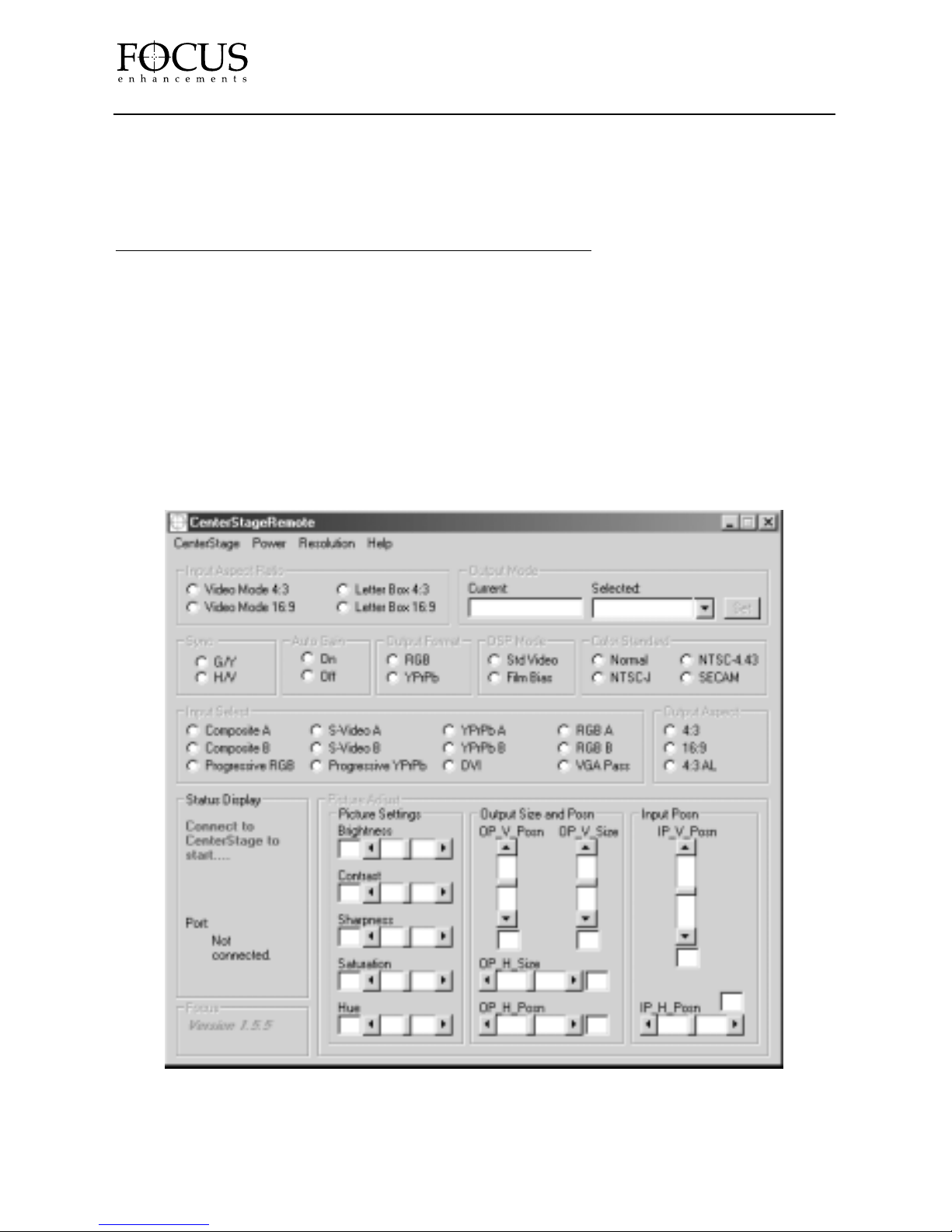
Once installed and you have connected CenterStage to your computer and powered the unit on,
launch the CenterStage Remote Application by selecting Start -> Programs -> CenterStage
Remote. The following screen will appear:
You will need to know which COM port you have connected the serial cable from CenterStage
to your computer and its Baud Rate. This will be either COM 1 or COM 2. Consult your computer
settings or documentation if you are unsure.
PAGE 24
CenterStage
Page 25
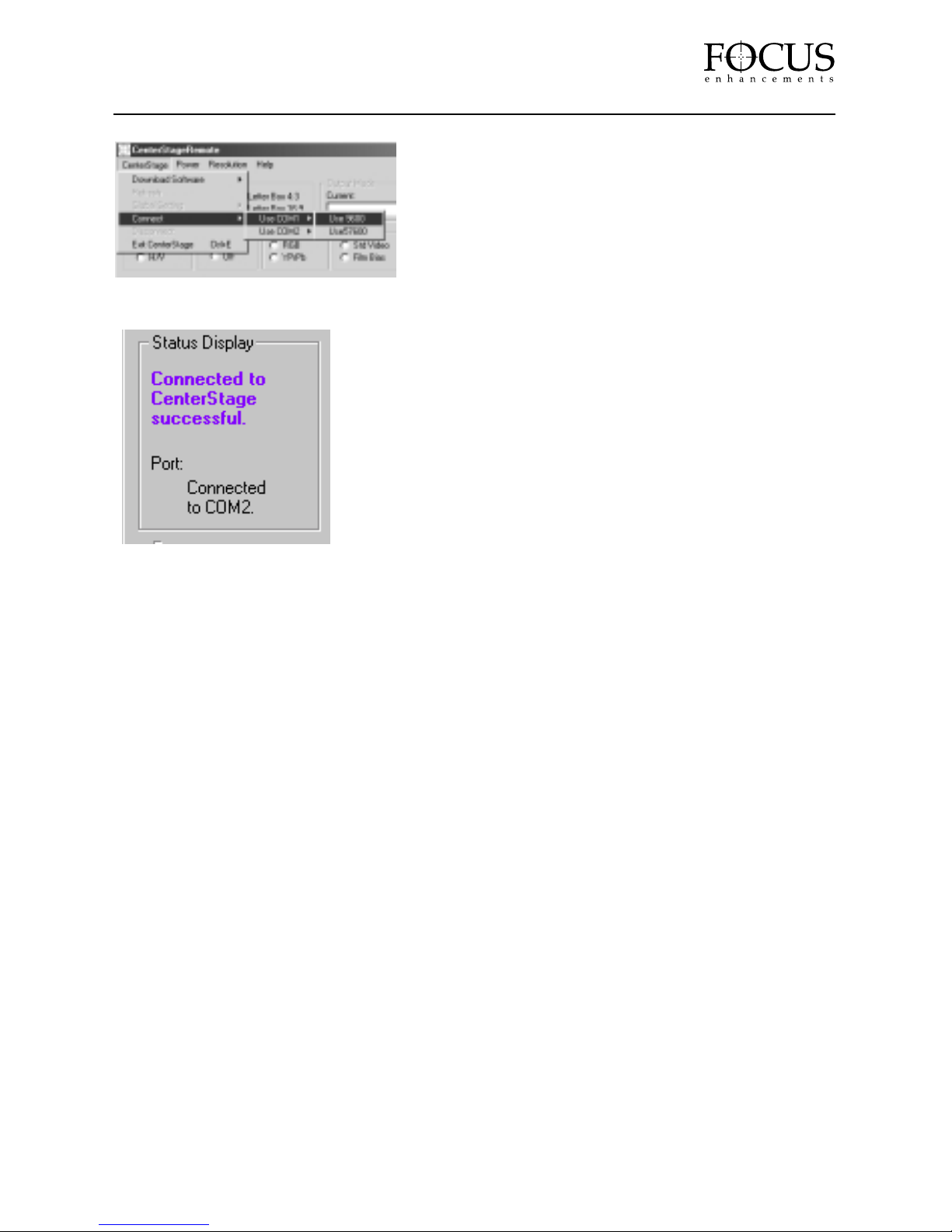
Under STATUS DISPLAY on the CenterStage Remote
window, you will see “Port: Not Connected”. To connect,
Go to the CENTERSTAGE pull down menu and select
CenterStage -> Connect -> Use COM1 or Use COM2.
Select the appropriate COM port. You will also need to
know the baud rate your computer's serial port is set to. With
CenterStage, you can select either 9600 or 57600. Consult
your computer's documentation for more information.
If you do not connect after a few seconds, quit the
CenterStage Remote Application and restart it. Try
a different COM port, a different Baud Rate and/or
check your cable and connections. Once connected,
you will see the following window:
Once connected it is possible to change the following:
INPUT ASPECT RA TIO: Select between Video Mode 4:3, Video Mode 16:9, Letterbox 4:3
and Letterbox 16:9 input aspect ratios. These settings are unique for each individual input.
OUTPUT MODE: Displays the current output resolution. Allows selection of any of the available
outputs. Changing the Output Mode will change the output on CenterStage and display its settings
on CSR.
SYNC: Allows sync to be switched between G/Y and H/V.
AUTO GAIN: Selects Auto Gain ON or OFF. Use Auto Gain when viewing material off-air,
through a cable box or satellite receiver.
OUTPUT FORMAT: Selects either RGB or YPrPb as the output for mat.
DSP MODE: Selects either Standard Video or Film Bias. Use Film Bias on programs that
originated on f ilm
COLOR STANDARD: Selects color standard as either NORMAL, (NTSC-US and PAL) NTSCJAPAN, NTSC 4.43 (PAL 60Hz) and SECAM.
INPUT SELECT: Allows for selection of the available inputs on CenterStage. Selection of a
particular input source will make that source the current input. Each input source also has
customizable settings.
PAGE 25
CenterStage
Page 26
OUTPUT ASPECT : Selects the output aspect ratio to either 4:3, 16:9 or 4:3 AL
(anamorphic lens).
PICTURE ADJUST: Allows adjustment of Input Brightness, Contrast, Shar pness, Saturation,
Hue, Output Size and Position (horizontal and vertical) and Input Position (horizontal and vertical).
It is possible to make custom settings for each individual input.
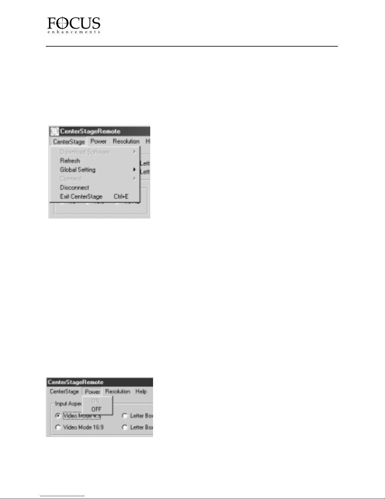
The CenterStage Remote Software also features the following Pulldown Menus:
DOWNLOAD SOFTWARE: Allows for downloading of the latest CenterStage Software. See
previous section.
REFRESH: Refreshes and updates the CenterStage Remote Software Window Display.
GLOBAL SETTING:Allows you to save a global setting of your CenterStage on your computer.
Global Setting takes a “Snapshot” of your system for later recall. Select SAVE to save your settings
and LOAD to restore a previous setting. This is of par ticular use when upgrading system software.
CONNECT: Enables connection between CenterStage and a computer system. It is possible to
select either COM port 1 or 2, and 9600 or 57600 Baud Rates on the computer.
DISCONNECT: Disconnects CenterStage from the current session with a computer.
EXIT CENTERSTAGE: Exits from the CenterStage Remote Software. Exiting will immediately
disconnect CenterStage from any connected computer system.
The Power Menu allows the CenterStage Unit to be turned ON or OFF remotely.
PAGE 26
CenterStage
Page 27
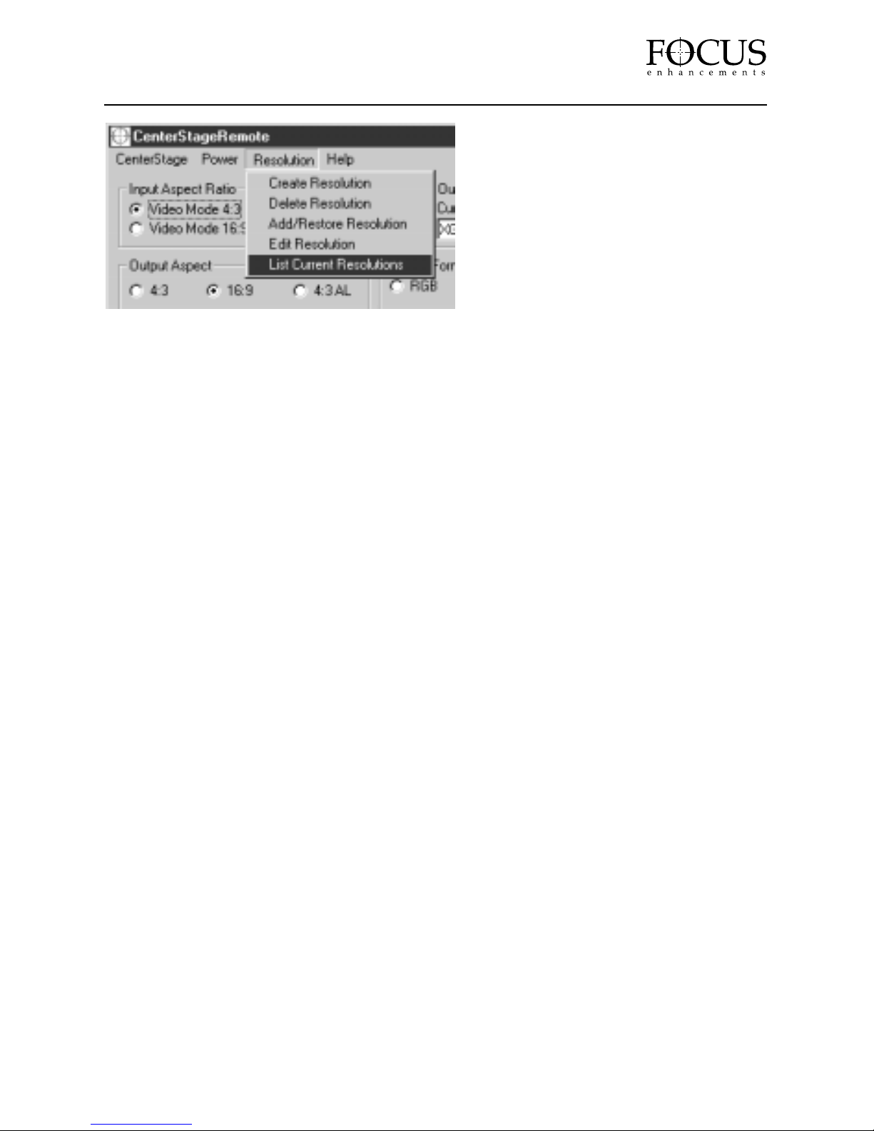
The Resolution Menu features the following functions:
CREATE RESOLUTION: Allows you to create custom resolutions. WARNING: CUSTOM
RESOLUTIONS ARE NOT SUPPORTED BY THE FOCUS’ ENHANCEMENTS TECHNICAL
SUPPORT GROUP. IT IS ADVISED THAT YOU HAVE A SOUND TECHNICAL KNOWLEDGE
BEFORE ATTEMPTING TO CREATE YOUR OWN RESOLUTIONS. In this window, it is
possible to set:
1.
HORIZ TOTAL – Number of horizontal pixels (including active front porch, back porch and
sync width).
2.
VERTICAL T O TAL – Number of vertical lines (including active front porch, back porch
and sync width).
3.
HORIZ ACTIVE – Number of active horizontal pixels.
4.
VERTICAL A CTIVE – Number of active vertical lines.
5.
H SYNC WIDTH – How wide the horizontal sync width is (in pixels).
6.
V SYNC WIDTH – How wide the vertical sync width is (in lines).
7.
H BACK PORCH – How wide the back porch is (in pixels).
8.
V BACK PORCH – How wide the back porch is (in lines).
9.
VERSION – This allows the user to allocate a version number to their particular resolution.
The version number must be something other than 0.
10.
REFRESH X 10 – The output resolution refresh rate. For example, for 60 Hz, type in 600.
11.
RGB/YPrPb – Selects either RGB or YPrPb as the output resolution standard. For resolutions
based on either 720p, 1080i or 1080p, this setting will set to YPrPb only. It is not changeable.
12.
SYNC POL – The sync polarity setting for the output resolution. Choose between:
• Horizontal sync Positive / Vertical sync Positive
• Horizontal sync Positive / Vertical sync Negative
• Horizontal sync Negative / Vertical sync Positive
• Horizontal sync Negative / Vertical sync Negative
13.
SAVE AS [STAR T WITH “_”] – Allows you to save the resolution with a custom name. Any
created resolutions MUST start with an underscore ( _ ). This will identify it as a custom
resolution. Non-underscored resolutions are factory resolutions. NOTE: CUSTOM
RESOLUTIONS ARE NOT SUPPORTED BY THE FOCUS ENHANCEMENTS’
TECHNICAL SUPPORT GROUP.
14.
CALCULATE DOT CLOCK – Calculates the dot clock for the particular output resolution.
The maximum allowable dot clock frequency is 135MHz. You will not be able to create a
resolution with a higher value.
PAGE 27
CenterStage
Page 28
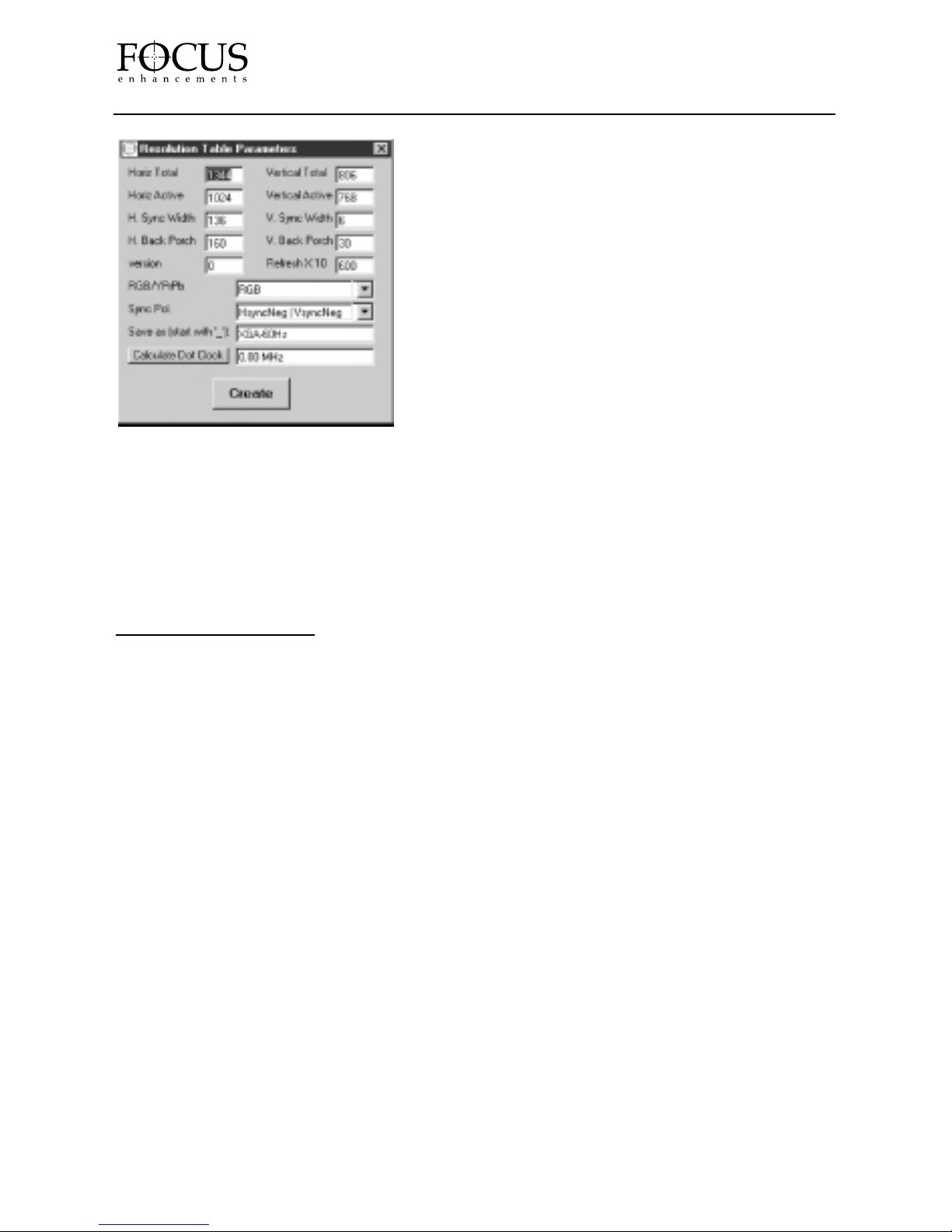
15. CREATE – Pressing this button will create
the new resolution and add it to the available list
on your CenterStage unit. Before saving, you
will be prompted to save a backup copy of the
resolution. This allows you to save a copy on your
computer system for later loading or recall.
(use “. res” as the file extension).
DELETE RESOLUTION: Allows for deleting of
any current resolution. WARNING: DELETING A
RESOLUTION IS UNDOABLE! It is not possible to
delete a factory resolution.
ADD/RESTORE RESOLUTION: Allows for adding of any resolution you may have saved on
you computer system.
EDIT RESOLUTION: Allows you to edit the timing and name of an existing resolution.
LIST CURRENT RESOLUTIONS: Displays the list of resolutions currently on CenterStage.
ABOUT DVI & HDCP
CenterStage CS-1 and CS-2 Video Processors suppor t the most common flavor of digital
source and display standards, DVI. With DVI, or the Digital Visual Interface, video remains digital
from the graphic source (PC, DVD, HTPC, etc. ), through the CenterStage, and to the display
(television, monitor, projector, plasma, etc. ). The CenterStage DVI input will accept the following
input resolutions:
640x480 60Hz 1024x768 60Hz
720x576 60Hz 1280x960 60Hz
800x600 60Hz 1280x1024 60Hz
High-bandwidth Digital Content Protection (HDCP) is a content protection scheme used with DVI
to prevent unauthorized copying and redistribution of digitally perfect content. Original content
via computer display cards or game consoles, and video from standard definition DVD players
will not likely be content protected. High-definition set-top boxes are expected to be HDCP
enabled to protect high-definition movies and pay-per-view programming. DVI with HDCP is
standard on CenterStage CS-2, and optional on CenterStage CS-1, so both are fully compatible
with any HDTV installation.
When using an HDCP encrypted DVI input source, analog output is disabled.
For more information on upgrading your CenterStage CS-1 to enable HDCP, contact FOCUS
Enhancements’Technical Support (for more information, see page 7 of this manual. )
PAGE 28
CenterStage
Page 29

TECHNICAL SPECIFICATIONS
INPUT
Horiz. Range (Interlaced): NTSC 15. 734kHz, PAL 15. 625 kHz
Vert. Range (Interlaced): NTSC 30Hz, PAL 25Hz
Horiz. Range (Progressive): 31. 5kHz
Vert. Range (Progressive): 60Hz
Horiz. Range (DVI): 31. 5kHz to 63. 9kHz (input resolution dependent)
Vert. Range (DVI): 60Hz
Color Standards: NTSC, NTSC-J, PAL (50), NTSC 4. 43 (PAL 60), SECAM
Connectors: (2x) Composite – RCA or BNC (CS-2)
(2x) S-Video (Y/C) – 4 pin mini DIN
(2x) Component (YPrPb or RGB) – RCA or BNC (CS-2)
Progressive (YPrPb) – RCA or BNC (CS-2)
Digital (DVI-D) receptacle
Computer Pass-Through HD-15 male (VGA)
Aspect Ratios: 4:3 (standard), 16:9 (widescreen), 4:3LB (letterbox) and
16:9LB (letterbox)
Memory: Auto-save input parameters
Adjustments: Contrast, Brightness, Saturation, Hue, Sharpness
Power Usage: 100-240 VAC, Auto-ranging 50 to 60Hz
Optional Accessories: HD15 to BNC cable, rack mount brackets and screws (CS1
only, standard feature on CS2)
Warranty: Two years
Weight & Size: CS-1 Tabletop w/ feet
17" x 9" x 4", 9. 5 lbs
430mm x 229mm x 102mm, 4. 3kg
CS-2 Rackmount
19" x 9" x 4", 9. 5 lbs.
483mm x 229mm x 102mm, 4. 3kg.
OUTPUT
Frame Rate: Computer/VESA 60, 72 and 75Hz
Connectors: Digital DVI-D receptacle
HD-15 female (VGA)
Aspect Ratios: 4:3, 16:9 and Anamorphic Lens Support
PAGE 29
CenterStage
Page 30

APPENDIX A
RS-232 pin configuration
CenterStage requires a standard AT style cable for connection to the RS-232 port. The pin
conf iguration of the port is as follows:
RX Data Pin 3
TX Data Pin 2
GND Pin 5
No handshaking provided or required.
RS-232 Control Protocol
NOTE: This section is intended for those with a strong technical knowledge. This information
is not needed for day to day understanding of CenterStage operation. If you have any questions
about control, consult your dealer or distributor or contact Focus Enhancements, Inc. directly.
It is possible for CenterStage to be controlled by RS-232 control codes for compatibility with
several Home Theater control systems. The interface should be able to control almost all aspects
of the unit. The structure provides for setting features of the unit, as well as interrogating the box
for it's current settings.
Protocol:
The protocol has the following 6 byte command structure for the interface.
Attention Byte: 0xEE
Number of Bytes to follow: 0x04
Command Byte: 0x00 through 0xDF
Data Byte 0: MS hex digit, 0-9, A-F, ASCII Value
Data Byte 1: LS hex digit, 0-9, A-F, ASCII Value
Checksum Byte The 7 bit sum of the preceding 5 bytes.
The Attention Byte is a unique code.
The Number of Bytes to follow includes the Command Byte, Data Bytes and Checksum Byte.
The Command Byte would range from 0x00-0xDF, so that they never overlap the Attention Byte range.
The Data Bytes express an eight bit value from 0 through 255 if viewed as an unsigned number, or -128
through 127 if it specifies a relative adjustment or a signed number. Each Data Byte is the ACSII
representation of the hex digit.
The Checksum Byte would be the sum of the five preceding bytes, with the MSB set to “0”
Command Bytes:
Command Bytes are documented in the spreadsheet RS-232Control Codes. XLS, and at the end of
this document.
There are specif ic Command Bytes for Writing to the CenterStage registers, and a different set of
Command Bytes for interrogating (Reading) the CenterStage for it's current settings.
Read Commands:
When a READ Command is written to CenterStage, the Protocol above is followed, with the Data
Bytes being set to “0”. The CenterStage will respond with the same 6 byte command str ucture,
but the Data Bytes will be filled in with the current setting. The client must wait for either a valid
response or an error response (NAK) before proceeding with additional communications.
Absolute Write Commands:
When an Absolute Write Command is written to CenterStage and the command is recognized as
valid, the Data Bytes will be used to change the setting of the selected function. The client MUST
wait for either an ACK or NAK before proceeding with additional communications.
PAGE 30
CenterStage
Page 31

Relative Write Commands:
When a Relative Write Command is written to CenterStage and the command is recognized as
valid, the Data Bytes will be used to adjust the setting of the selected function. The Data Bytes
will be treated as a signed byte. For example, an “FF” (-1), will lessen the setting by one, and a
“05” will increase the setting by five. The client MUST wait for either an ACK or NAK before
proceeding with additional communications.
BAD Commands:
When an invalid command is received by CenterStage, it responds with an ASCII NAK (0x15).
GOOD Commands:
When a valid command is received by CenterStage, it responds with an ASCII ACK (0x06).
Handshaking:
As described above, all commands to the CenterStage will be responded to by either an ACK,
NAK, or a Read_Response. It is suggested that the Client monitor the replies by waiting for an
Attention Byte after a Read Command, an ACK, or a NAK. The Client should disregard all other
received bytes until it receives one of the specific bytes mentioned above.
Limits:
It should be expected that many registers would have limits on the range of the Data Byte. If a
command is received where the Data Byte value falls out of the range of acceptable values, the
CenterStage will be set at the Limit, and the Data Byte of the response from CenterStage will
reflect that limit. The response will not reflect the erroneous value.
Command Set:
The Command values given below are for a Relative Write Command. The values for an Absolute
Write Command are the values listed below + 0x30. The values for a Read Command are the
values listed below + 0x60.
#define WRITE_POWER 0x50
#define WRITE_INPUT_ASPECT 0x51
#define WRITE_VID_PROC 0x52
#define WRITE_SELECT_INPUT 0x53
#define WRITE_OUTPUT_ASPECT 0x54
#define WRITE_RESET 0x55
#define WRITE_FRONT_PANEL 0x56
#define WRITE_OUTPUT_RES 0x57
#define WRITE_SHARPNESS 0x60
#define WRITE_CONTRAST 0x61
#define WRITE_BRIGHTNESS 0x62
#define WRITE_V_SZ_MODE_INPUT 0x63
#define WRITE_V_POS_INPUT 0x64
#define WRITE_H_SZ_INPUT 0x65
#define WRITE_H_POS_INPUT 0x66
#define WRITE_V_SZ_OUTPUT 0x67
#define WRITE_V_POS_OUTPUT 0x68
#define WRITE_H_SZ_OUTPUT 0x69
#define WRITE_H_POS_OUTPUT 0x6A
#define WRITE_COLOR_ADJUST 0x6B
#define WRITE_TINT_ADJUST 0x6C
#define WRITE_OP_FMT 0x6D
#define WRITE_COLOR_ MODE 0x6E
PAGE 31
CenterStage
Page 32
APPENDIX B
Input Aspect Ratio to Output Aspect Ratio Primer
WHAT INPUT ASPECT RATIO SETTINGS DO
(4:3 Mode) If you are playing a DVD, and the DVD player is in “Normal TV” mode, a circle will appear as a
circle on a standard TV. In this case, you should have the Input Aspect Ratio set to 4:3. This preserves a circle
as a circle, and does not stretch the image horizontally. You should use 4:3 input mode if the DVD player is in
“Normal TV” mode, even if the movie is a wide screen movie.
(16:9 Mode) If you have the DVD player set to “Wide TV” mode or “Anamorphic mode”, a circle will appear as
a tall oval on a standard TV. In this case, you should set the CenterStage to have the Input Aspect Ratio set to 16:9.
This mode stretches the image horizontally, and changes the tall oval back into a circle on the display device!
(4:3LB Mode) If you have the CenterStage in 16:9 Output Mode with content that is standard 4:3 (black
bars on the left and right when displayed on a standard TV), and you don't like the black bars on the left and
right of the displayed image, then you should set the CenterStage Input Aspect Ratio to 4:3LB mode. This will
expand the image vertically and horizontally to eliminate the black bars on the left and right, as well as expand
the image and crop the top and bottom, filling the screen. This 4:3LB Input Mode only makes sense when you
are in 16:9 Output Mode.
(16:9 LB Mode) If you have the CenterStage in 16:9 Output Mode with content such as a 2. 35:1 DVD
(black bars on the top and bottom even when displayed on a 16:9 display), and you don't like the black bars on
the top and bottom of the displayed image, then you should set the CenterStage Input Aspect Ratio to 16:9LB
mode. This will expand the image cropping the far right and left, and eliminating the black bars on the top
and bottom, filling the screen.
WHAT OUTPUT ASPECT RATIO ACTUALLY DOES
Display devices today have either a 4:3 aspect ratio or a 16:9 aspect ratio. A typical LCD or DLP projector is
made from a 4:3 display element, and will want to display a 4:3 image at its maximum resolution. CRT projectors
can be adjusted to be either 4:3 or 16:9 output. There are also 16:9 native CRT direct view monitors and some
rear view projection displays that are inherently 16:9 as well.
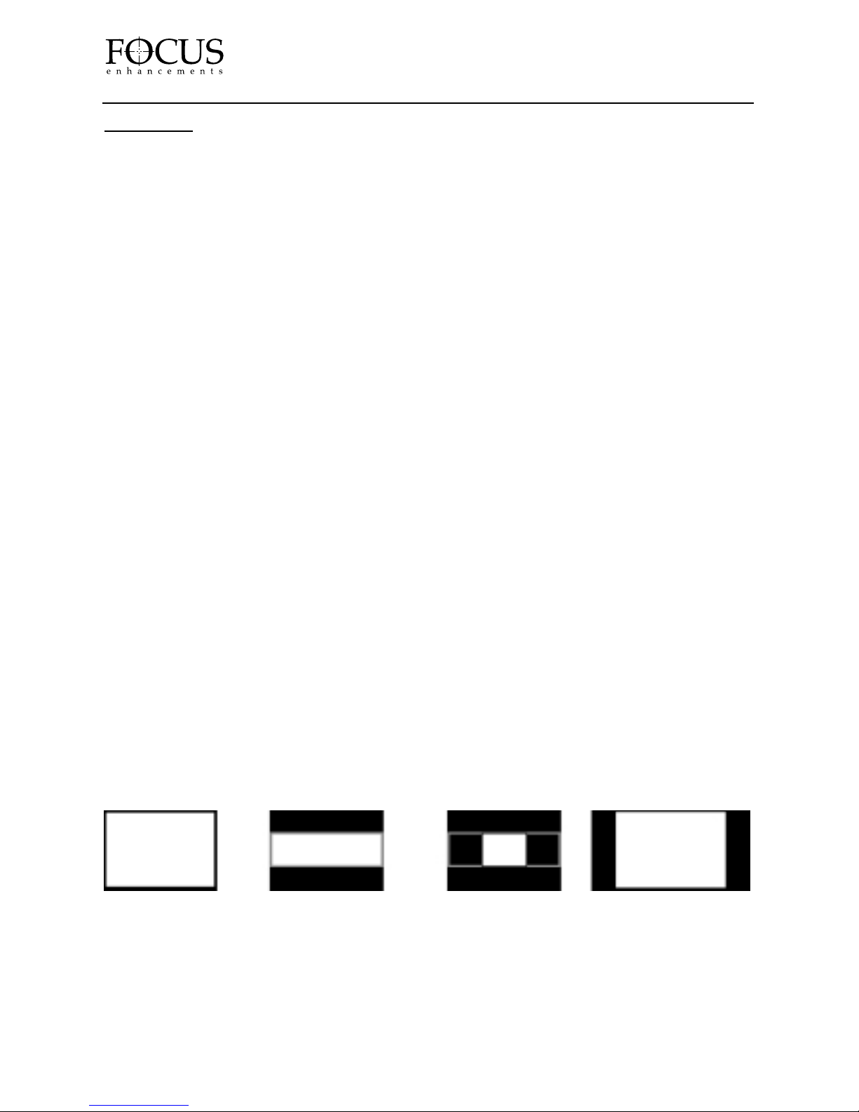
If you had a native 4:3 display device (let's say an XGA projector, 1024x768), you could project it on a 4:3
screen, and it would display its full resolution on that screen, (See Example A). If you took the same 4:3
display device and projected it on a 16:9 screen, you would lose a portion of the display resolution off the
top and bottom of the screen (making this area black). You would only be viewing a portion of that XGA
resolution (1024x576 to be exact). The remaining 192 lines (768-576=192 lines) would need to display black
data so that you are not projecting an image on your wall above and below the screen, (See Example B). This
portion of the original resolution of the display is lost! A wide screen movie would look great, but a 4:3 image
would need to be centered in the 16:9 screen to look right. It will have lost a lot of its resolution, since now
only a small central box of the original 1024x768 display resolution can be used to display the image. This box
is now 768x576. See Example C.
Example A Example B Example C Example D
If your display device is native 16:9, and you are projecting on a 16:9 screen, the CenterStage should be set
for 16:9 output. A wide screen movie should fill the screen assuming that the movie is also 16:9 or 1. 78:1. If
the movie is wider, for example 2. 35:1, you will see some black area on the top and bottom of the screen due
to the image being wider and shorter than 16:9. If you are viewing a 4:3 image, you will see black bars on the
right and left sides of the image, because a 4:3 image is not wide enough to fill the screen. See Example D.
PAGE 32
CenterStage
Page 33

NOTES:
PAGE 33
CenterStage
Page 34

FOCUS Enhancements, Inc.
1370 Dell Ave. Campbell, CA. 95008 USA
Telephone: 408 866-8300 Fax:408 866-4859 www.FOCUSinfo.com
 Loading...