

Page 1
ABH-50L 50m 1.6m
ABH-100L 100m 2.0m
ABH-150L 150m 2.6m
ABH-200L 200m 3.4m
ABH-250L/P
250m
4.4m
1
1
2
2
4
4
557
7
668
8
3
3
TAMPER
TAMPER
COM NO NC
ALARM
4-φ4.5
13
1
1
1
2
1
2
2
2
2
2
3
3
3
4
4
4
1
1
13
11
11
11 11
4*60mm
4*60mm
POWER
DC10v-24v/AC9v-18v
20mA max
◆
◆
◆
POWER
DC10v-24v/AC9v-18v
70mA max
Quad Photoelectric Beam Detector User Manual
Thanks for purchasing quad photoelectric beam detector, please read the user manual carefully
before installation.
WARNIN G
CAUTI ON
Do not use the product for purposes other than the detection of moving objects such as people and
vehicles. Do not use the product to activate a shutter, etc.which may cause an accident.
Never attempt to disassemble or repair the product. It may cause fire or damage to the devices.
Do not exceed the voltage or current rating specified for any of the terminals during installation,
doing so may cause damage to the devices.
Do not touch the unit base or power terminals of the product with a wet hand ( do not touch when the
product is wet with rain etc.) It may cause electric shock.
Do not pour water over the product with a bucket, hose, etc. The water may enter which may cause
damage to the devices.
Clean and check the product periodically for safe use. If any problem is found, do not attempt to use
the product as it is and have the product repaired by a professional engineer or electrician.
1. Features
Interruption time adjustable
NO / NC relay outputs
Integrated tamper switch, turns on when cover is moved.
Frequencies selectable for long distance and stacking installation
LED display signal grade for easy alignment
Wide voltage and energy-saving design
“And” “Or” technology
Digital communication function
FRES NEL lens
IP65 Waterproof grade: IP65
Alignment angle horizontally ±90°, vertically ±10°
Digital filtering, high environment adaptability to eliminate false alarms
Anti-beam interference, workable in harsh situations.
2.Part Description
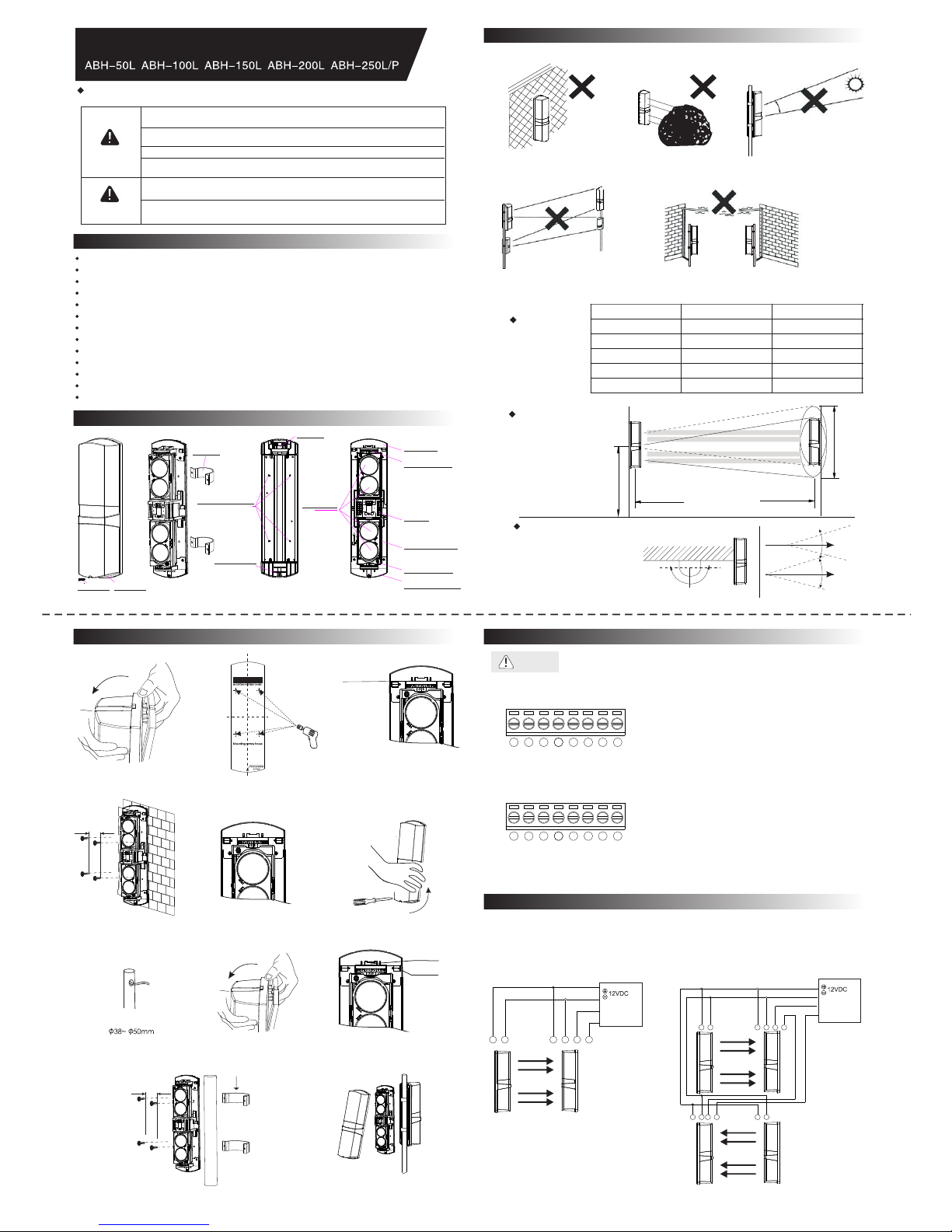
Front Cover
Front Cover
Base
Body
Lock Screw
U Bracket
Mounting Plate Holes
Cover Lock Nut
Wire Hole
Fresnel Lens
Up-bracket
Horizontal adjust
Terminals
Vertical adjust scale
Vertical Alignment
Screw
Horizontal Alignment
Bolster
3. Installation notes
1.Please avoid below situations to assure performance
1.Do not install on the unsteady
or not soiled surface
2.Do not install the unit where objects
can block the beams like the plants
and laundry can be moved by wind.
3.Prevent direct sunlight or fluorescent
object entering into internal receiver.
4.Avoid any other detector interference
(stack installation only for same model)
5.Avoid aerial wiring
2.Normal installation
Detection distance
Mounting height
Model Detection Distance Beam Angle
Beam spread range
Beam spread range
Detection Distance
Mounting height 0.7~1.0m
Detection Distance
Adjusting Angle
Horizontal 180°(±90°)
Vertical 20° (±10°)
Notice: For best testing results,
please avoid testing in 45°
4. Setting method
1.Wall mounting
1.Loosen the screw and remove the cove
2. Attach the installation paper to the wall,mark
the holes first and then make the guide holes.
3.Wiring hole: Remove the foam plug,pull
wire through.and reset the foam plug.
Wiring Knockout
4.Drop into the four holes with the
expansion pipes,fix them with screws.
5.Connecting wires to the terminals
(please refer to “beam alignment”)
6.Review and reset the cover
2.Pole mounting
Bracket diameter
1. Break out the wire hole and pull out
the wires.
2. Remove the cover
3. Drop into the holes with the expansion
pipe,fix it with screws
Wiring Knockout
Wiring Pressing
U type bracket
4.Fix the body on the bracket
5. Back to back installation diagram,others
please refer to the step 5 and 6 of the wall
mounting method.
5. Connectors
Warning
when installation , don't connect the port with the voltage or current which is
over the normal specification!
Transmitter
Receiver
Notes:
1 . Power voltage input: .DC10v-24v/AC9v-18v
2 . No heater in the package, please order if required.
3 . The tamper switch is independent of other circuit;
it would open if the cover was removed
Notes:
1 . Power voltage input: .DC10v-24v/AC9v-18v
2 . No heater in the package, please order if required.
3 . The tamper switch is independent of other circuit;
it would open if the cover was removed.
4 . Relay connection point 1C 24VDC 0.5Amax
6.Connecting wires
1.Single connect: Control panel operating
voltage DC12V. NC alarm output.
Connecting to power supply parallel
Alarm input
Alarm input
Control panel
Control panel
Transmitter
Transmitter
Receiver
Receiver
2.Stacked connect. Control panel operating
voltage DC12V.NC alarm output series
connect
plate
scale
Page 2
■
250m
500m
200m 1000m
100m
1250m
150m 750m
2
2
1 1 3 4 1 2 3 4 1 2
ABH-50L ABH-100L ABH-150L ABH-200L ABH-250L
50m
150m
300m
100m
300m
150m
450m
200m
600m
250m
750m
Detecting distance(max)
Detecting method
Interruption time
Frequencies
Power and voltage
Current consumption
Alarm cycle
Alarm output
Tamper
IP rating
Operating temperature
Humidity
Сorrection angle
Install location
Weight
105
395
100
M
O
D
E T
A
M
P
E
R SE
T
POWER
L1
L2
L3
L4
POWER
L1
L2
L3
L4
60
186.4
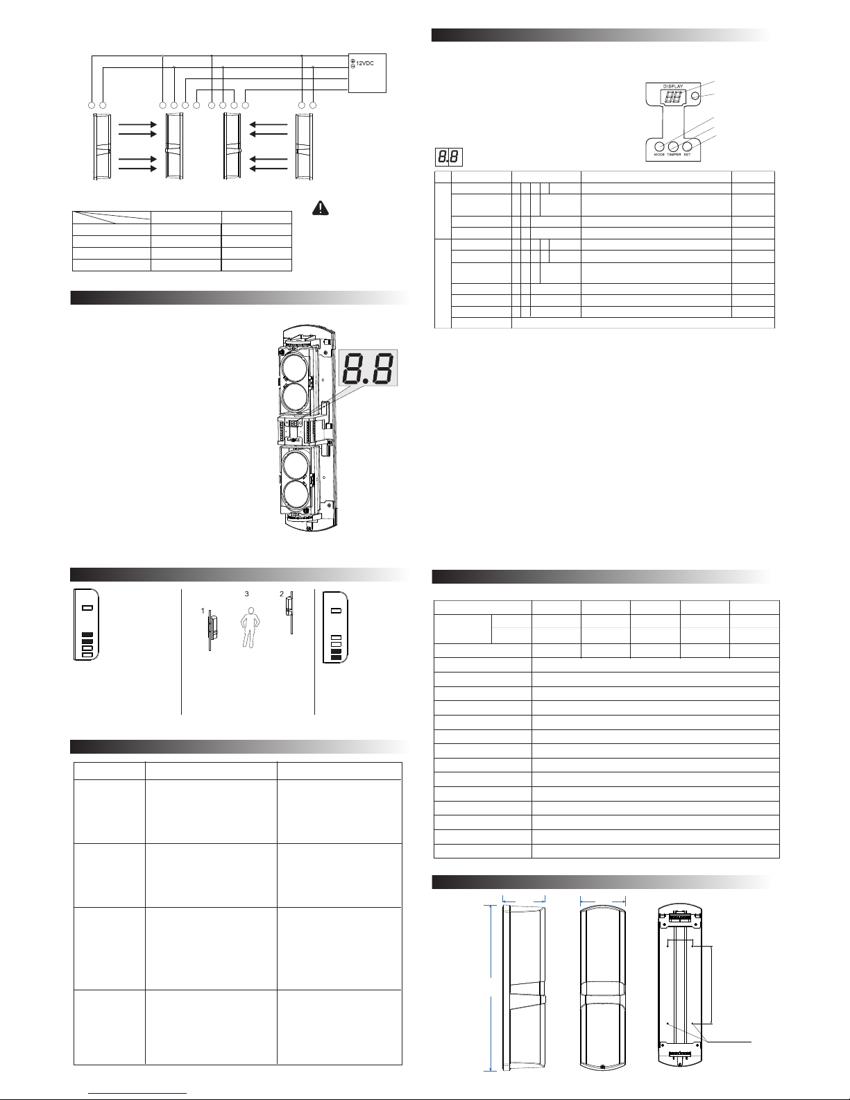
3.Control panel operating voltage DC12V. NC alarm output series connect as follows:
Alarm input
Control panel
Transmitter
Transmitter
Transmitter Receiver
Receiver
Receiver
The distance between the power and the detector should not be longer than following.
Wire diameter
Length
Voltage
DC12V DC24V
Warning
1. The power line can not exceed the listed
length.
2. When connecting multiple detectors,
the required cable length is divided by
the corresponding numberof units listed.
3. Don't connect the port with the voltage
or current which is over the normal
specification!
7.Digital tube voltage indicator
Digital tube indicator (on the top of PCB shell)
3 button setting(on the bottom of PCB shell)
(1)Adjust the beam frequency switch, make sure
the frequency of transmitter must be the same
as frequency of receiver.
(2)Set the transmitter and receiver in 30 model.
Adjust the screw and bracket until in alignment
(3)Adjust the screw and bracket,set the receiver's
voltage display mode to max.The indication of
digital tube will change between “0.0” to “3.8”.“0”
indicates no signal and send alarm output.when
optical axis aligning,the digital tube indicator
should be not less than “2.5”.then the upper two
beams in alignment.
(4)Set the transmitter and receiver in 31 model.
repeat the (2)(3) steps,make the bottom two
beams in alignment.
(5)Then set the transmitter and receiver in 32 model,
finished alignment.
(6)Operation confirmation.Please make sure the
alarm indicator is off before testing. If not please
redo the alignment.until the detector into normal
alarm state.
Introduction: the program setting is realized by two button (MODE, SET) and 2 bits digital tube display, easy to operate.
MODE button: it is used for change parameters. Press once to change a parameter, single circulation conversion.
SET button: it is used to set value of parameter under chosen MO DE, Press once to change a parameter, single
8.Button setting
Transmitter: 1. MODE parameter setting sequence: frequency->
debugging mode->detection mode->LED switch
2. Press button for 3 seconds to restore the MODE
parameters factory setting (10, 32, 40, 50)
Receiver: 1. MODE parameter setting sequence: frequency->
block infrared time->debugging mode->detection
mode->LED switch->buzzer switch->signal degree
2. Press button for 3 seconds to restore the MODE
parameters factory setting (10, 20, 32, 40, 50, 60, 0.0)
Digital tube display
Photosensitive window
(on receiver)
MODE menu button
Tamper button
Setting value button
MODE parameter value setting
Transmitter
Parameters Value setting Description
Frequency 1 0
0
0
0
0
0
0
0
0
0
40
40
32
32
10
20
1
1
1
1
1
1
1
1
1
2
2
2
2
2
3
3
3
Setting value:0~3 refers to adjustable 4 kinds of frequency
Factory defaulted
value
Debugging mode 3
0:only open above two infrared beams
1:only open below two infrared beams
2:open all four infrared beams
Detection mode 4
Defaulted value is 0. Not editable
LED switch 5
0:open LED 1:close LE D
50
50
10
60
Receiver
Frequency 1
Setting value:0~3 refers to adjustable 4 kinds of frequency
Block infrared time 2
Setting value:0~3 refers to adjustable 4 kinds of
interruption infrared time
Debugging mode 3
0:only open above two infrared beams
1:only open below two infrared beams
2:open all four infrared beams
Detection mode 4
0:”and” mode 1:”or” mode
LED switch 5
0:open LED 1:close LE D
Buzzer switch 6
0:open buzzer to make sounds 1.close buzzer
Signal degree
Two bit digital tube is used for display the signal degree, like 2.5 means the signal voltage degree is 2.5V
MODE parameter setting introduction:
1.Frequency: using MODE button to change into this parameter; the digital tube displays the number among10~13. Press
SET button; the frequency increases one degree, single circulation among 10~13. 4 kinds of frequency selectable to avoid
adjacent photoelectric beam sensors signal interference
2.Block infrared time:the digital tube displays the number among 20~23. Press SET button; the frequency increases one
degree, single circulation among 20~23. 4 kinds of frequency selectable.
3.Debugging mode:the digital tube displays the number among 30~32. Press SET button; the frequency increases one
degree, single circulation among 20~23. 3 kinds of frequency selectable:30:only open above two infrared beams31:
only open below two infrared beams 32:open all four infrared beams
4.Detection mode:the digital tube displays the number among 40~41. Press SET button; the frequency increases one
degree, single circulation among 40~41. 40:”AND” mode, means simultaneous interruption of four infrared beams to send
alarm signal40:”AND” mode, means simultaneous interruption of above two infrared beams or below two infrared beams to
send alarm signal.
5.LED switch: the digital tube displays the number among 50~51. Press S ET button; the frequency increases one degree,
single circulation among 50~51. 50: open LED; 51: close L ED
6.Buzzer switch: the digital tube displays the number among 60~61. Press SET button; the frequency increases one degree,
single circulation among 60~61. 50: open buzzer 51: close buzzer
7.Signal degree: it uses voltage value to display. The higher voltage value; the stronger signal degree. the digital tube displays
the number among 0.0~3.5. 1.8V signal display is photoelectric beam sensor normal work basic requirement.According
channel LED indicator will become green.
Notes:
1.The detection mode and frequency of transmitter and receiver must be the same. After finishing debug above and below
two infrared beams, please make debugging MODE into “32”, or the product could not normally work.
2.If the tamper of transmitter and receiver is opened, the receiver will send alarm signal
3.After finish debugging, suggest closing LED indicator and buzzer to save energy, and opening tamper function.
4.If there is without pressing button operation within 30 minutes, the digital tube display will close; if pressing again, it will light.
Operation indicator
Operation indicator
Alert status
Alert status
Alarm indicator
Alarm indicator
Please walk test under below three
locations to block infrared
1.Before transmitter
2.Before receiver
3.Among transmitter and receiver
When infrared is interrupted,
the product is in alarm status.
L1&L2 LED indicators turn off;
L1&L2 LED indicators turn on,
which
means
installation
succeeds.
Note: if the infrared is interrupted and the L1&L2 LED indicators do not turn on, please refer to item 10 to troubleshooting
9.Walk test
10.Troubleshooting
Symptom
Possible cause
Remedy
Power on, but
indicator LED
does not light
(off)
1. DIP switch is in the state of saving
electricity
2. Power cable without voltage;
broken circuit or short circuit;
polarity is incorrect; beyond
specified voltage; power cable
exceeds the specified length.
1. Turn on the DIP switch
2. Check power adapter, circuit
and voltage polarity; change
adapter or power cable
When beam is
blocked,alarm
LED does not
light and alarm
1. There are reflectors or other
transmitters impacting receiver
2. 4 beams are not all blocked
3. Setting too long interruption time
4. Alarm output cable is fixed
Incorrectly
1. Remove reflectors or close other
transmitters; adjust receiver
2. Ensure 4 beams all blocked
3. Reduce interruption time
4. Check receiver terminal and
output cable
When beam is not
blocked, alarm LED
lights and alarm
1. Beam is out of alignment; optical
axis does not overlap
2. There are objects between
receiver and transmitter
3. Frequency is incorrect
4. The cover is dirty or capped
by snow, frost and ice
5. Transmitter dose not output
6. Model switch status is incorrect.
1. Adjust optical axis
2. Check objects between receiver
and transmitter
3. Ensure the frequency of receiver
and transmitter the same
4. Clean cover and use heater
5. Check the power, current and
cable of transmitter
6. Check model switch setting
False alarm
1. Bad wiring and fluctuant power
voltage
2. Movable blocks, like bird, paper,
leaves
3. The installation base is unstable
4. Out of alignment
5. Infrared beam deviate optic axis
1. Check power, current and wiring
2. Change the installation location
3. Strengthen installation base
4. Adjust optical axis
5. Adjust the single optical axis
11.Specifications
Model
(outdoor)
Detecting
distance
(indoor)
12.Dimensions
DC10V-24V/AC9V-18V
600m 900m 1200m 1500m
Simultaneous interruption of 4 infrared beams
4 different frequencies (selectable)
IP65
-25℃~55℃
95% max
Horizontally 180°(±90°); 20°(±10°)
Indoor/outdoor, wall/pole
2.20kg
0.5m㎡(diameter 0.8)
0.75m㎡(diameter 1.0)
1.0m㎡(diameter 1.2)
1.5m㎡(diameter 1.4)
circulation conversion.
Please make sure alarm L ED
indicator: L3&L4 turn off. If L1&L2
LED indicators turn on and there
is without blocks among
transmitter and receiver, please
realignment.
150mA max
50ms, 100ms, 300ms, 700ms (adjustable)
Installationholes
Relay output (NC/NO) 1C. contact output. DC/AC30V/0.5AMax
NC. Works when cover is removed
2±1S
 Loading...