


INSTALLATION & USER INSTRUCTIONS
All instructions must be handed to the user for
safekeeping.
MODELS COVERED BY THESE INSTRUCTIONS
ND-18D1 AUGUSTA ELECTRIC STOVE F500417
WALL MOUNTED ELECTRIC FIRE
Please note : Except where otherwise stated, all rights,
including copyright in the text, images and layout of this
booklet is owned by Focal Point Fires plc. You are not permitted to copy or adapt any of the content without the
prior written permission of Focal Point Fires plc.
1
Revision A - 10/11
© 2011 Focal Point Fires plc.
AUGUSTA
GB IE
Superior Fires
Christchurch, Dorset BH23 2BT
Tel: 01202 588 632
Fax: 01202 499326
www.superiorfires.co.uk
e : info@superiorfires.co.uk

• DO NOT use this appliance immediately below a fixed socket outlet.
• DO NOT use this appliance in the immediate vicinity of a bath, shower, swimming pool or other area where water/moisture
could present a hazard.
• DO NOT allow the heater to be covered as this may cause overheating. The appliance must not be placed near curtains or sim-
ilar material. A clearance space of at least one metre must be allowed in front of the appliance. A clearance space of 100mm each
side must be allowed. A clearance space of 50mm must be allowed for the back of the appliance.
• CAUTION: This appliance must not be used in conjunction with any timer, programmer or thermal control, or any other device
that will switch on the appliance automatically, as a fire risk may occur if the heater is accidentally covered or displaced.
• The electrical socket that the appliance uses MUST be easily accessible. Do not route the supply cord directly in front of the
heater unit.
• If the cord is damaged, it must be replaced by a service agent or competent person.
• This appliance is not intended for use by persons (including children) with reduced physical, sensory or mental capabilities, or
lack of experience and knowledge, unless they have been given supervision or instruction concerning use of the appliance by a
person responsible for their safety.
• Children should be supervised to ensure that they do not play with the appliance.
The appliance is supplied with a pre-wired three pin BS1363 plug plug (13Amp fuse rated) and 1.6 metres of electrical flex. It is
therefore necessary for a suitable electrical socket to be located within this distance of the appliance and be easily accessible. The
stove may be installed on a combustible or non-combustible floor, however the heater outlet is underneath the stove and certain
types of floor covering may be affected by the heat produced by the stove. The ability of the floor covering to withstand the heat
produced by the stove should be ascertained before proceeding with the installation of the stove. If in doubt then the stove should
be mounted on a non-combustible hearth or plinth which extends for at least 150mm in front of the stove.
This appliance should be positioned on a firm level surface. If the stove is to be sited in a fire surround then the suitability of the
surround for use with electrical heaters should be established with the fire surround manufacturer.
If fitted into an open draught fireplace, it is advisable to block off the chimney to reduce the risk of draught through the stove
which may cause the safety cut out system in the fan heater to operate.
Read all the instructions before continuing to unpack or install this appliance. Carefully lift the appliance from the carton. Check
that the contents correlate with the component checklist below. Please dispose of all packaging with care at your local recycling
centre.
QUANTITY DESCRIPTION
1 Heater
1 User instruction booklet
1.0 IMPORTANT NOTES
INSTALLATION & USER INSTRUCTIONS
© 2011 Focal Point Fires plc.
2
GB IE
© 2011 Focal Point Fires plc.
2.0 INSTALLATION REQUIREMENTS
3.0 APPLIANCE DATA
Supply Voltage : 230-240v~50Hz Fuse Rating : 13 Amp
Heating Elements : 2 x 900W Lighting : 2 x 25W E14 bulb
Location : Indoor use only Supply plug/cord : BS1363/1.6 metres length
4.0 UNPACKING THE APPLIANCE
5.0 COMPONENT CHECKLIST
Section Contents Page No.
1.0 Important Notes 2
2.0 Installation Requirements 2
3.0 Appliance Data 2
4.0 Unpacking the Appliance 2
5.0 Component Checklist 2
6.0 Operating the Appliance 3
Section Contents Page No.
7.0 Safety Cut-Out System 3
8.0 Maintenance 3
9.0 Cleaning 3
10.0 Spares 3
11.0 Servicing 4
12.0 Appliance Dimensions 4

Check that the fan outlet is not covered or obstructed in
any way, and ensure the power to the fire is switched on.
The appliance controls are concealed behind a panel on the
front of the heater.
Switch ‘e’ turns on the flame effect. Knob ‘f’ controls with brightness of the flame effect. Turn knob ‘f ’ until the desired effect is
achieved.
Switch ‘b’ controls the fan function. The fan may be operated without heat, or without the flame effect. With the fan running, switch
‘c’ turns on heat setting 1 (900W), and switch ‘'d' controls heat setting 2 (1800W). The fan must be switched on for the heat settings to work. The fan and heating functions can be operated with or without the flame effect. The appliance is fitted with a thermostat. To adjust the thermostat, turn knob ‘a’ until the desired room temperature is achieved.
This appliance has a safety cutout system fitted which will activate if the air inlets or outlets are obstructed. For safety reasons
the fire will NOT switch on again automatically, the following procedure must be carried out before the fire can be operated.
NOTE: The visual effect will remain operational if the cutout is activated, only the fan heater is prevented from working.
Switch OFF the appliance at the wall socket or outlet. Leave the fire OFF for a period of no less than 10 minutes, ensuring all
obstructions are removed. Switch the appliance ON at the wall. Ensure the appliance is turned ON at the control switches. If
the fire fails to operate correctly, repeat the above procedure. If an attempt to switch on the appliance is made before the safety cutout has reset, the appliance may cutout for a further period of time. If the sequence has been followed correctly and the
appliance still fails to function, check the fuse in the wall outlet. If this is not the cause, call an electrician or maintenance engineer.
ALWAYS DISCONNECT THE APPLIANCE FROM THE MAINS SUPPLY BEFORE
UNDERTAKING ANY MAINTENANCE.
Excluding lamps and fuses, use only genuine spare parts available from your supplier. Replacement lamps must be of the same
wattage and specification as those stated in Section 2.0 Appliance Data.
Replacing the light bulbs.
1) Disconnect the appliance from the mains.
2) Open the door.
3) Remove the three screws at the front of the decorative fuel bed. Remove the fuel bed clamp.
4) Lift up the decorative fuel bed.
5) Two bulbs are located under the decorative fuel bed.
6) Unscrew and replace the bulb(s) using only 25W E14 type.
7) Re-assembly is the reverse of removal.
There is no specific requirement for care of the fire other than a regular cleaning of the general appliance.
The decorative MDF casing is not removable for cleaning. A wipe with a dry cloth is normally sufficient. DO NOT use abrasive
cleaners as they can damage the finish. Brass and silver parts of the fire may be cleaned using a appropriate metal polishes.
Refer to Section 2.0 Appliance Data for lamp and fuse specification. Excluding lamps and fuses, use only genuine manufacturers
spare parts available from your supplier.
©
2011 Focal Point Fires plc.
6.0 OPERATING THE APPLIANCE
GB IE
‘a’
‘b’ ‘c’ ‘d’
‘e’
‘f ’
‘a’ Thermostat
‘b’ Fan (without heat)
‘c’ Heat 900W
‘d’ Heat 900W
‘e’ Flame effect on/off
‘f ’ Flame effect dimmer
7.0 SAFETY CUTOUT SYSTEM
9.0 CLEANING
8.0 MAINTENANCE
10.0 SPARES
3
There are no internal user serviceable parts.
Check regularly for security of wall fixings as appropriate. Also check security of supply cable and connections. If the supply cable
becomes damaged, it must be replaced by a service agent or competent person, such as a qualified electrician.
The wires in the cable are coloured in accordance with the following code:
LIVE - Brown
NEUTRAL - Blue
EARTH - Green/Yellow
Refer to Section 2.0, Appliance Data for fuse specification. Excluding fuses, use only genuine manufacturers spare parts available
from your supplier.
As our policy is one of continuous improvement and development, we therefore hope that you will understand we must retain the right to amend details and/or specifications without prior notice.
4
© 2011 Focal Point Fires plc.
11.0 SERVICING
Waste electrical products should not be disposed of with household waste. Please recycle where facilities exist. Check with your local authority or retailer for recycling advice.
F861089
GB IE
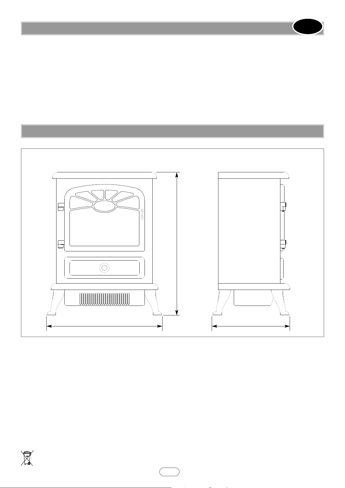
12.0 APPLIANCE DIMENSIONS
430 290
540
All dimensions in mm
 Loading...