

Page 1
TM#
#################### #
##
#
#
Where Art Meets Science
#
#
#
#
#
#
#
#
#
#
#
MPA-2 Dual Channel Class A Microphone Preamplifier
Operating Manual
Page 2

MPA&2#Operating#Manual############################################## ############Ver.#1.2###2016# ################
2#
Contents
Description
Safety Information
Installation
Front Panel Controls
Rear Panel Connections
General Unit Operation
Specifications
Warranty
Contact Information
Page 3

MPA&2#Operating#Manual############################################## ############Ver.#1.2###2016# ################
3#
Description
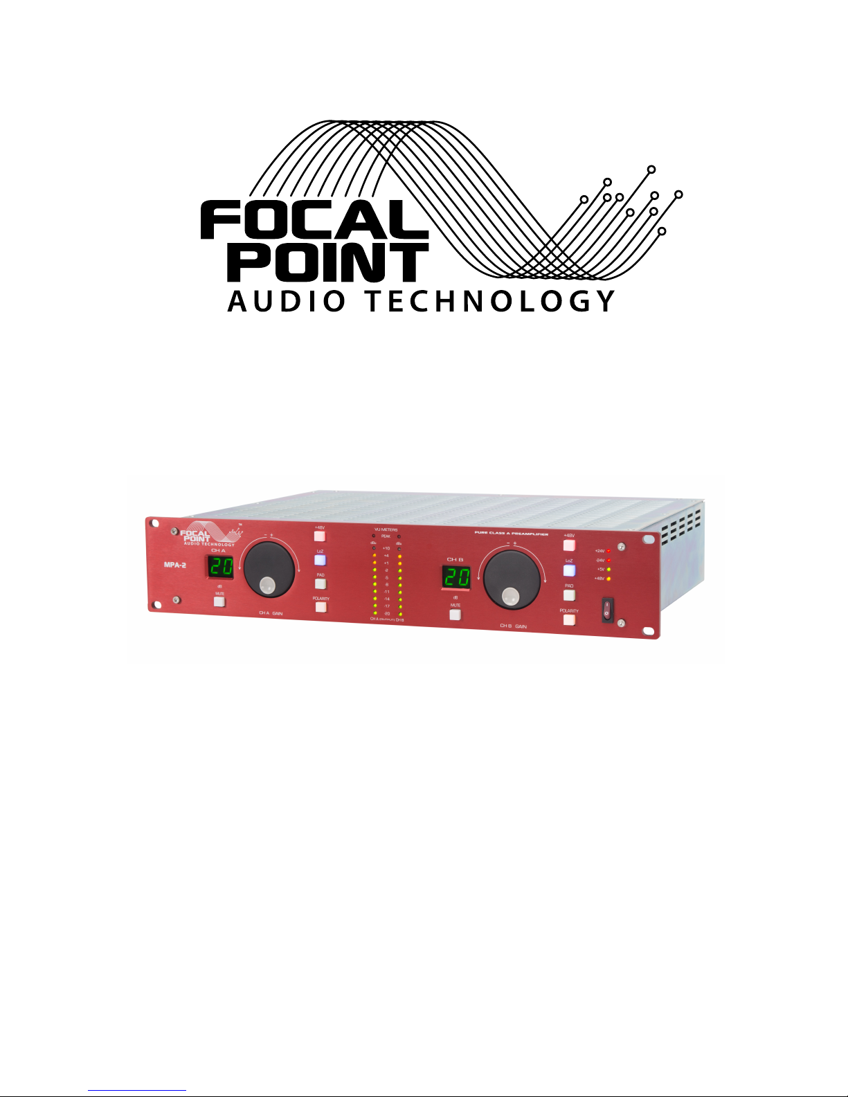
The MPA-2 is a two channel Pure Class A Microphone Preamplifier. The topology of the
MPA-2 is fully discrete circuitry. There are no IC’s or capacitors in the audio path. The
MPA-2 is a true DC coupled output and a transformer coupled input.
The front panel consists of channel A and channel B controls. Both channels have the
following.
Rotary encoder for gain setting.
Dual 7 segment LED for indication of channel gain setting.
10 LED’s for output metering.
1 LED for indication of peak level. (Set to +24dBu).
Mute pushbutton.
+48V pushbutton.
Lo z Input option. Use with low impedance microphones. (Adds an additional small
resistance for low impedance microphones to optimize the transformer input
impedance).
20dB Input pad.
Polarity. (Inverts input polarity).
Located on the right side of the unit is the AC mains switch and LED indication for
power supply status.
The front panel controls for both channels are handled by microcontrollers that setup
the gain , LED’s , Encoder operation , Internal switching.
The rear panel consists of the AC mains input with fuse and voltage select. There are
identical connectors and indicators for both channel A and channel B. These consist of
the following;
Microphone XLR input.
Dual XLR output. (Both outputs are paralleled).
Indication of Phantom Power enabled on input.
Last setting memory, will return to prior setup if the unit loses power.
Page 4
MPA&2#Operating#Manual############################################## ############Ver.#1.2###2016# ################
4#
Input SwitchingInput XLR
1st Stage Gain!
Pre Amp
2nd StageGain!
Pre Amp
Front Panel!
Microcontroller
Mux Mux
Function Sw's!
Gain LED's
Non Inverting!
Line Amp
Inverting!
Line Amp
Servo Servo
Servo Servo
Mute Relay Output XLR's
Encoder
Metering!
!
Peak LED
+24V Low
Noise!
Regulator
-24V Low
Noise!
Regulator
+5V Low
Noise
Regulator
Power!
Supply
+18V Servo!
Metering!
Regualtor
-18V Servo!
Metering!
Regulator
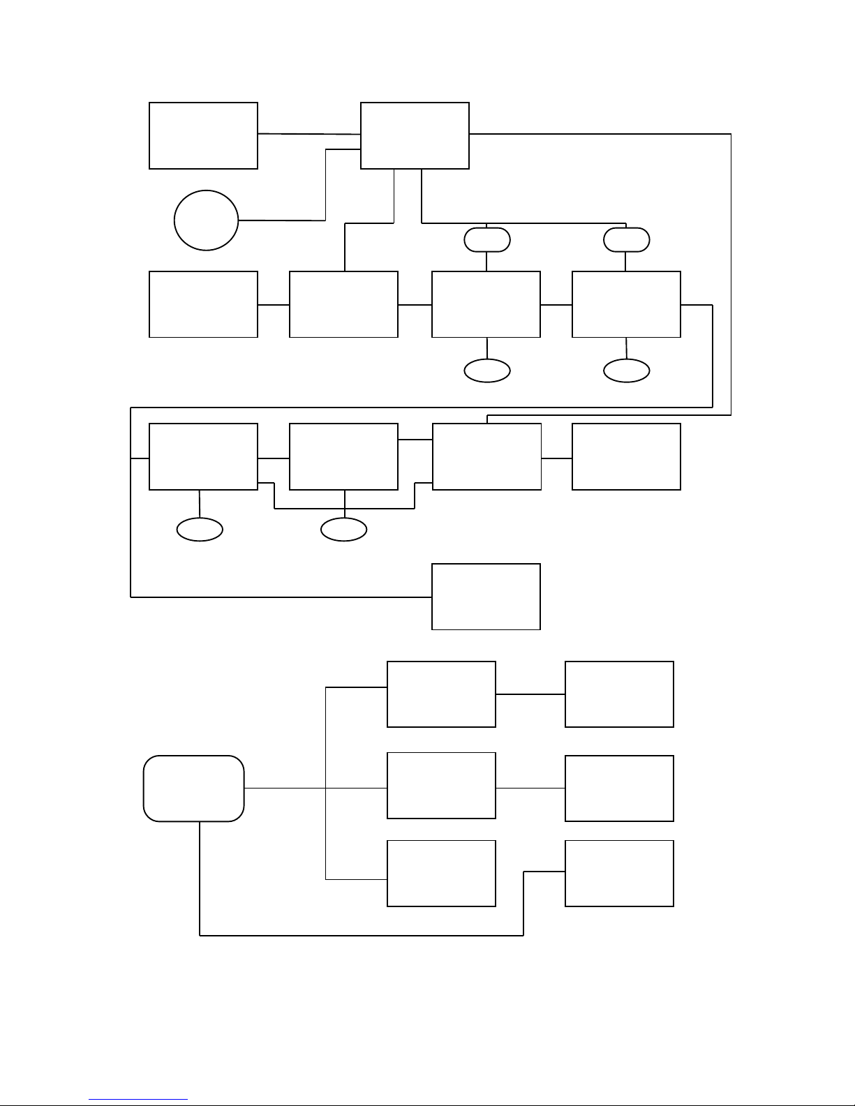
MPA-2 Internal Flow Diagram
+48V!
Phantom!
Supply
Page 5

MPA&2#Operating#Manual############################################## ############Ver.#1.2###2016# ################
5#
Safety Information
Please observe the rear panel fuse rating and replace with the same type and rating
fuse.
Set the correct operating voltage prior to applying power the MPA-2.
If replacement fuse blows return the MPA-2 for service. Do not install larger fuse. This
will case damage to the unit as well as possible harm to the user.
Do not expose the MPA-2 to moisture, this could cause damage to the unit and cause
harm to the user.
Do not allow fluids to leak into the top lid vent slots. Damage to the unit will occur.
There are no user replaceable parts inside.
Do not attempt to service the MPA-2. There are dangerous voltages inside the unit.
Do not cut the U ground (3rd pin) on the AC cord. This could cause harm to the user.
Avoid blocking the top and side vents of the MPA-2. This could cause the unit to heat
up and cause possible failure.
If rack mounting the unit use all 4 front panel rack mount holes. The MPA-2 is heavy
and may sag in the rear if all 4 screws are not used. Use fiber washers under the
screws to prevent front panel damage and scratching to the front panel anodize
plating.
Page 6

MPA&2#Operating#Manual############################################## ############Ver.#1.2###2016# ################
6#
Installation
Verify operating voltage before applying AC mains. Replace fuse as needed for correct
voltage setting.
Install in a location that will give the MPA-2 proper ventilation on the top and sides.
Try to avoid mounting the MPA-2 near any other equipment that may emit large
magnetic fields like power amplifiers. The unit may pick up stray fields and pick up hum.
Plug in input XLR connectors and make sure they are all the way in.
Plug in output XLR connectors and make sure they are all the way in.
The two output connectors are paralleled and can drive two pieces of equipment.
Careful not to load down the MPA-2 with too low of an output impedance.
Dual outputs and be used for sending one output to monitor rack and the other to Pro
Tools rig if needed. Dual outputs have application for live sound support as well. If only
one output is needed leave the other XLR unused.
Pay close attention to the rear panel “Phantom Power Enabled” LED. Make sure what
you are plugging in to the XLR input requires phantom power. This voltage can cause
catastrophic damage to some ribbon type microphones. This LED is illuminated only
when the +48V function has been enabled from the front panel.
Page 7
MPA&2#Operating#Manual############################################## ############Ver.#1.2###2016# ################
7#
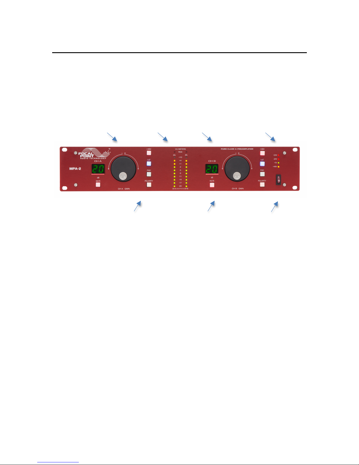
Front Panel Controls
Gain control encoders Output Meters Gain Settings Power Supply LED’s
+48, LoZ, Pad, Polarity Switches Mute Switch AC Mains Switch
Page 8
MPA&2#Operating#Manual############################################## ############Ver.#1.2###2016# ################
8#
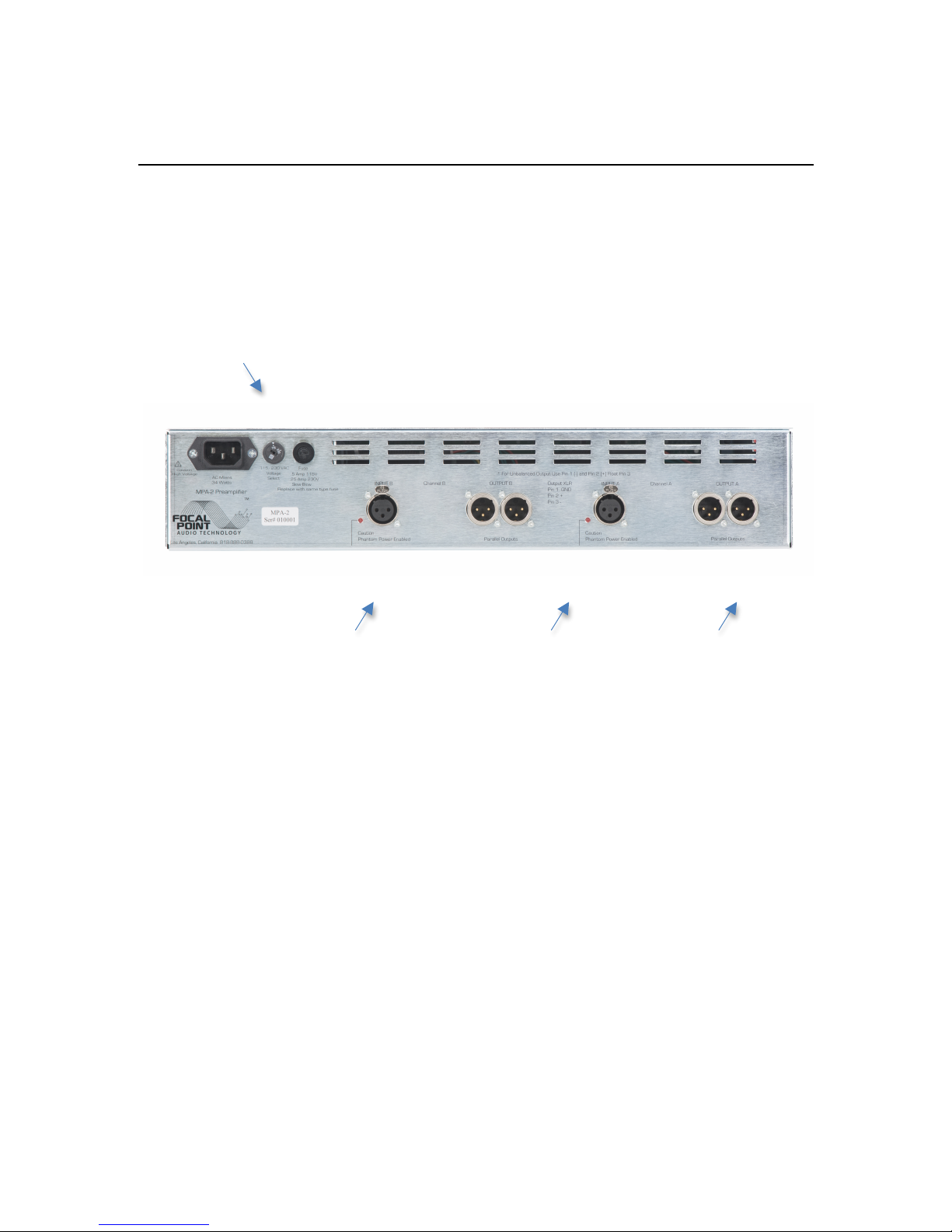
Rear Panel Connections
AC , Select, Fuse
XLR Input Phantom Enable LED XLR Outputs
Page 9

MPA&2#Operating#Manual############################################## ############Ver.#1.2###2016# ################
9#
General Unit Operation
The operation of the MPA-2 Microphone Preamplifier is fairly straightforward. Both
channel A and Channel B are identical in operation.
All controls and adjustments are done on the front panel. Gain control is accomplished
by means of a front panel rotary encoder that adjusts the gain from 20dB to 70dB in
2dB steps. The gain setting is displayed on the dual 7 segment front panel LED.
All front panel controls are handled via a microcontroller that handles all functions on
the main audio board as well as the display and switch functions on the front panel.
Once you power up the MPA-2 the unit will stay in mute for 10 seconds to allow the
unit to stabilize. The unit will also mute for one second when you switch in any of the
options such as +48V, Pad, LoZ, Polarity. This is to avoid any loud popping on the
output. The same is true when you switch out any of the options, the unit will again
mute for one second.
All the front panel power supply LED’s should be illuminated. If one if the LED’s are out
contact the factory as the unit may require service.
All pushbutton functions will illuminate the pushbutton to an on state. Once the function
is no longer enabled the pushbutton LED will extinguish. All LED’s have a small standby
current applied so they will appear very dim but never totally go out. The Mute
pushbutton will flash while the unit is booting up at startup.
It will take at least 20 minutes for the MPA-2 to fully come up to operating
temperature. At that time all output offset voltages as well as the internal servos will
have had enough time to settle.
The front panel LED meters read the MPA-2 output as it relates to balanced operation.
The peak LED is factory set to come on at +24dBu (Balanced out). There is a 2 second
hold on this LED. VU meters have a damped response for average level.
The MPA-2 uses a 2 dB step for gain change. *Because this is a step gain control
there will always be a small step click when changing gain.
The front panel optical encoder controls will rotate without hitting a stop. Once you
reach the full 70dB gain spinning the encoder will not increment the display any longer.
The same holds true for the minimum gain setting.
There are no internal user adjustments or settings.
For unbalanced operation follow the instructions on the rear panel. DO NOT GROUND
PIN 3. FLOAT THIS PIN FOR UNBALANCED OPERATION. USE PIN 2 AS THE OUTPUT.
Recall last front panel settings. If the unit loses power the MPA-2 will power back up
and retain the last known setup on the front panel. This includes gain setting and all
front panel switch settings.
Page 10

MPA&2#Operating#Manual############################################## ############Ver.#1.2###2016# ################
10#
Specifications
Circuit topology: Fully discrete Class A. No overall global feedback. Transformer
coupled input, DC coupled output.
Input switching / Output muting : NEC sealed relays.
Inputs: 2 XLR.
Outputs: 2, 4 XLR’s. 2 paralleled connectors on each channel.
Front Panel Controls: Gain, Mute, +48V, LoZ, PAD, Polarity, AC Mains.
Metering: 10 LED’s ,1 Peak LED , Per Channel. Peak set to+24dBu output
Regulation: Independent bipolar regulation on each channel. Separate supplies for
analog , analog servos and logic control circuits.
Front panel control: 8bit microcontroller.
Gain: 20dB to 70dB, in 2dB steps.
THD+N: .002%
IMD THD: 4:1ratio .003%
Inter-channel Phase: Less than 5 degrees 20 -20kHz
Noise: @20dB gain 22-22K, A Wtd -101dBu
Input Impedance: 1.2K nominal.
Output Impedance: Less than 30 ohms.
Frequency Response: 10 Hz – 100kHz. +0 / -3dB
Gain Control Accuracy: +/- .5dB. Multiplexer controlled.
Maximum Input: +10dBu @ 20 dBu gain setting.
Maximum Output: +32dBu.
Gain Accuracy Between Channels: +/- .5dB.
Power Requirements: 115VAC / 230VAC 34 watts.
Fuse Requirements: 120VAC .5A time delay, 220VAC .25A Time delay
Dimensions: 19” x 12.5” x 3.5”.
Weight: 18 LBS, 22 LBS Shipping wt.
Page 11

MPA&2#Operating#Manual############################################## ############Ver.#1.2###2016# ################
11#
Warranty
Focal Point Audio Technology warrants the MPA-2 Microphone Preamplifier for a
period of 1 year from date of purchase against defects in materials and workmanship.
This warranty is non-transferable.
Focal Point Audio Technology makes no other warranty, either express or implied,
including but not limited to implied warranties of merchantability, fitness for a
particular purpose, or conformity to any representation or description, with respect to
this product other than as is set forth below.
Focal Point Audio Technology makes no warranty or representation, either express or
implied with respect to any other manufacturers product or documentation, it’s quality,
performance, merchantability, and fitness for a particular purpose, or conformity to
any representation or description.
During the warranty period Focal Point Audio Technology will replace or repair at it’s
option any internal or external parts found to be defective. This is provided the product
has not been misused or abused, modified or shows physical damage.
Defects caused by misuse, abuse, modification, accidents, improper installation,
environmental conditions or unauthorized repairs, improper packaging or any
connectivity issues , improper AC mains selection are not covered.
Limits Of Liability
Focal Point Audio Technology liability, in contract, in tort, under any warranty in
negligence, or otherwise, shall not exceed the cost or repair or replacement of the
defective product or components. Under no circumstances shall Focal Point Audio
technology be liable for the cost of substitute products, incidental special, direct or
indirect or consequential damages including but not limited to damage to software,
recorded audio or visual material, attached, patched or connected peripheral
electronic equipment, cost of recording facility time, cost of defense, or loss of use,
revenue or profit even if Focal Point Audio Technology has been advised of the
possibility of such damages.
Page 12

MPA&2#Operating#Manual############################################## ############Ver.#1.2###2016# ################
12#
Contact Information
TM#
#
############# ##
Professional Audio Products
Focal Point Audio Technology.
Sales and Technical Support.
818-888-0388
Web: www.focalpointaudiotech.com#
Email: [email protected]
ENJOY YOUR SESSION
 Loading...