

Focal Point HANNINGTON BRASS F500310, HANNINGTON BLACK F500311 Installation & User's Instructions
Page 1
INSTALLATION & USER INSTRUCTIONS
All instructions must be handed to the user for
safekeeping.
MODELS COVERED BY THESE INSTRUCTIONS
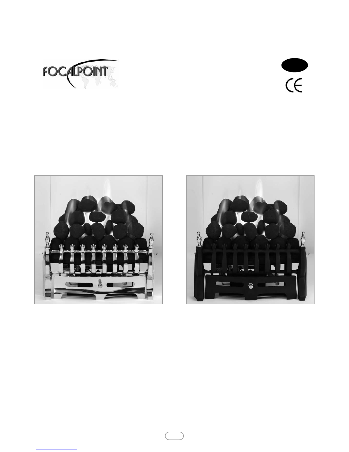
HANNINGTON BRASS F500310
HANNINGTON BLACK F500311
Focal Point Fires plc.
Christchurch, Dorset BH23 2BT
Tel: 01202 499330
Fax: 01202 499326
www.focalpointfires.co.uk
INSET DECORATIVE GAS FIRE
Please note : Except where otherwise stated, all rights,
including copyright in the text, images and layout of this
booklet is owned by Focal Point Fires plc. You are not permitted to copy or adapt any of the content without the
prior written permission of Focal Point Fires plc.
1
Revision A - 11/10
© 2010 Focal Point Fires plc.
HANNINGTON BRASS
GB IE
HANNINGTON BLACK
Page 2

• This appliance is an Inset Decorative Fuel Effect appliance which provides radiant warmth utilising the latest type
burner technology.
• The fire is designed to suit various types of fireplaces and natural draught flues as detailed in this manual.
• The appliance must be installed by a competent person in accordance with Gas Safety (Installation and Use)
Regulations 1998. It is strongly recommended that a GAS SAFE registered engineer be used for this purpose.
• Read all these instructions before commencing installation.
• This appliance must be installed in accordance with the rules in force and used only in a sufficiently ventilated
space.
• The appliance is designed for installation on to a non-combustible hearth of at least 300mm depth.
• This appliance is factory set for operation on the gas type, and at the pressure stated on the appliance data plate.
• In the event of gas leakage from the appliance, the gas supply must be turned off at the nearest isolating valve.
• The appliance must be installed in accordance with the following:
• Failure to comply with the above could lead to prosecution and deem the manufacturer’s warranty invalid.
• The appliance is designed to fit various types of situations as described in sections 3.0 and 4.0.
• It should be noted that heaters create warm air currents. These currents move heat to wall surfaces next to the
heater. Installing the heater next to vinyl or cloth wall coverings or operating the heater where impurities in the air
(such as tobacco smoke, candle smoke etc.) exist, may cause the walls to become discoloured.
• WARNING: The manufacturer of this appliance considers all surfaces as working surfaces with the exception of
the control knob and ash pan door. Where young children, pets, the elderly or infirm are concerned, a suitable fireguard should be used.
• Consult ALL instructions before installation and use of this appliance.
• This appliance is intended for decorative purposes.
• This appliance is free from any asbestos material.
• Refractories and fuel bed are constructed from ceramic fibre.
1.0 IMPORTANT NOTES
INSTALLATION INSTRUCTIONS
© 2010 Focal Point Fires plc.
2
GB IE
© 2010 Focal Point Fires plc.
• Manufacturers' Instructions.
• The Building Regulations issued by the Department for Communities and Local Government, the Building Standards
(Scotland)
(Consolidation) Regulations issued by the Scottish Development Department.
• Relevant British Standards insofar as the relevant areas are not covered by these instructions.
• For Republic of Ireland, reference should be made to the current edition of IS813 (the relevant standards governing
installation).
Section
1.0
2.0
3.0
4.0
5.0
6.0
6.1
7.0
8.0
9.0
Contents
Important Notes
Appliance Data
Installation Requirements
Site Requirements
Ventilation
Unpacking the Appliance
Component Checklist
Installing the Burner
Fuel Bed Layout
Fire Front
Page No.
2
3
3
3
4
4
4
4
5
5
Section
10.0
11.0
12.0
12.1
12.2
12.3
12.4
13.0
14.0
Contents
Testing & Commissioning
Operating the fire
Spark Gap
Setting Pressure
Flue Spillage Monitoring System
Testing For Spillage
Briefing the Customer
Servicing
Troubleshooting Guide
User Instructions
Page No.
5
5
5
5
6
6
6
6
7
Page 3
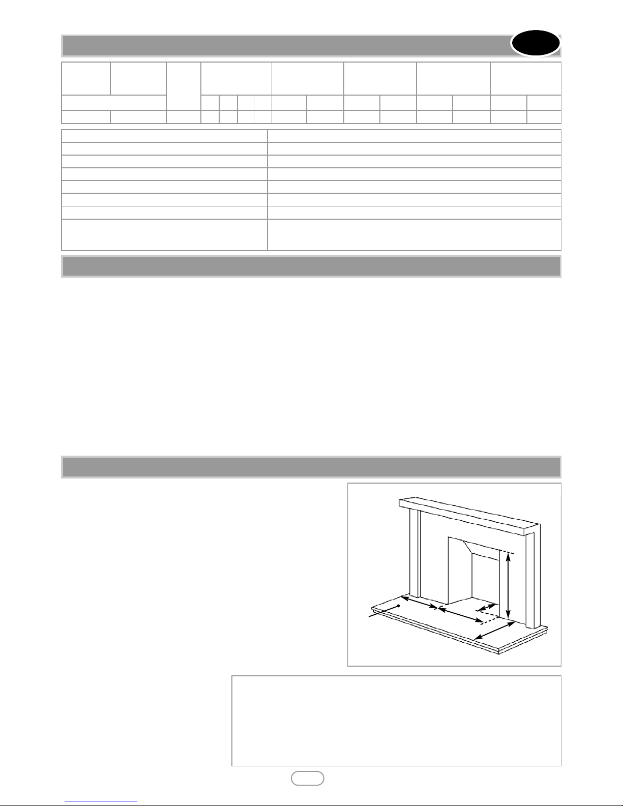
2.0 APPLIANCE DATA
3
Model
Destination
Country
Cat
Inlet Pressure
(±2.0 mbar)
Max Energy Input
(kW)
Min Energy Input
(kW)
High Burner
Pressure
(±1.5 mbar)
Low Burner
Pressure
(±0.75 mbar)
Natural gas
G20 G25 G30 G31 Gross Net Gross Net Hot Cold Hot Cold
Hannington
GB - IE
I
2H
20 -
- - 6.8 6.1 3.5 3.15 16.2 15.8 4.4 4.2
GB IE
© 2010 Focal Point Fires plc.
3.0 INSTALLATION REQUIREMENTS
This appliance MUST NOT be installed into a room containing a bath or shower, or where steam may be present. The fire has
been designed to fit into a builders’ opening or fireplace conforming to BS 1251 (and meeting certain dimensional requirements),
or a suitable flue box complying with the constructional requirements of BS 715. Either a ‘Replacement Chairbrick’ or a BS 1251
chairbrick should also be fitted into the builders’ opening. The flue box must be installed onto a suitable non-combustible insulating surface at least 12mm thick, covering the entire base are of the box.
The flue must have an effective height of at least three meters, as measured from the hearth to the top of the flue. Any flue damper
plates or restrictors should be removed and no other restriction fitted to the flue. Where removal is not practical, the restriction must be fixed in the fully open position. A natural draught flue system is required, and if previously used for solid fuel or oil
burning, the flue and chimney must be swept prior to appliance installation. The flue must be checked before installation by using
a smoke pellet or similar to ensure proper draw and that leakage is not evident at any joints. Repair and re-test as necessary
before the appliance is installed. The flue must be connected to only one fireplace, and the flue must not vent more than one appliance (i.e. not shared with a gas back boiler). There must be no opening in the flue apart from the one that the appliance is installed
into, and the one venting the gases into the air. A suitable terminal may be fitted, such as class GC1, as regulations allow.
This appliance has been tested for use with circular flues of a minimum internal diameter of 175mm. The flue termination (cowl)
must be of a type suitable for use with an inset Decorative Fuel Effect Fire BS5871 part 3 contains further details.
The fireplace opening should be inspected and repairs made where necessary. Any chair brick may be left in place.
The opening WIDTH and HEIGHT dimensions should be between
405mm and 440mm wide, and 565mm to 575mm high.
Opening DEPTH should be 220mm or greater. Opening DEPTHS
include any plaster or infill panels which form part of the installation.
This appliance requires a natural draught flue system which may be one
of the following;
• 225mm x 225mm (9in x 9in) brick or stone.
• 175mm (7in) minimum diameter lined brick or stone.
• 175mm (7in) minimum diameter twin wall flue conforming to BS 715.
Any existing under grate draught device must be sealed off.
The opening wall must be non-combustible.
The appliance requires a hearth with
non-combustible surface of at least
12mm thick.
The top surface must be at least 50mm
above the surrounding floor level, or be
surrounded by a raised edge or fender
50mm high.
Specifications Hannington - All models
Main burner injector Stereo size 81
Oxypilot (Natural Gas Models) SIT 9081
Gas Control (All Models) BM733/NGC6802A
Gas Inlet 8mm compression - Inlet restrictor elbow
Ignition Piezo Spark
Spark Gap (± 1.0mm) 4.0mm
Flue specification
225mm x 225mm (9in x 9in) brick or stone.
175mm (7in) minimum diameter lined brick or stone.
175mm (7in) minimum diameter twin wall flue conforming to BS 715.
4.0 SITE REQUIREMENTS
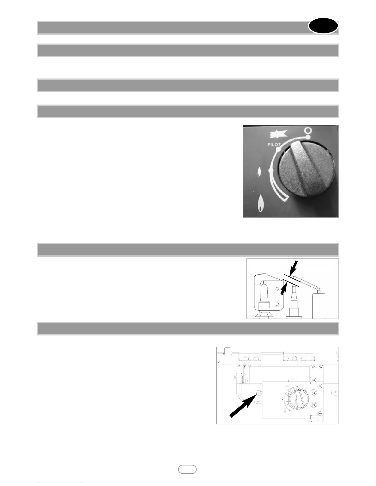
A. Opening height: 565mm min/575 mm max.
B. Opening width: 405mm min/440mm max.
C. Mounting depth: 220mm
D. Hearth must extend minimum of 150mm either side of the opening.
E. Hearth must extend minimum of 300mm in front of the opening.
F. Non-combustible hearth must be a minimum of 50mm in height, or be surrounded by a 50mm high fender.
‘A’
‘B’
‘C’
‘D’
‘E’
‘F’
Figure 1
Page 4

4.0 SITE REQUIREMENTS - CONTINUED
Any type of fire surround used with this appliance must be adequately sealed to the wall and floor.
A combustible shelf may be fixed to the wall above the fire, providing that it complies with the dimensions given below.
A non-combustible shelf may be fitted to within 10mm of the top edge of the fireplace opening.
Combustible materials, such as wood, may be fitted to within 100mm (4in) of either side of the fireplace opening , providing the
forward projection does not exceed 100mm (4in).
Any combustible side walls must be at least 500mm to the side of the radiant heat source.
As with all heating appliances, any decorations, soft furnishings, and wall coverings (i.e. flock, blown vinyl and embossed paper)
positioned too close to the appliance may discolour or scorch.
No purpose provided ventilation is normally required for this appliance. The requirements of other appliances operating in the
same room or space must be taken into consideration when assessing ventilation.
If spillage is detected when commissioning the appliance then amongst other problems there may be insufficient natural ventilation for the correct operation of the flue. This is potentially a greater problem should the property be of modern nature. If the
appliance does not spill with windows open but does with windows closed, this proves that lack of ventilation is the problem, if
not, it will be the flue at fault. Installation of an air brick in these circumstances may be the best solution. Any ventilation fitted
must comply with BS 5871 part 2 and BS 5440 part 2. Ventilation located underneath or within the immediate vicinity (one metre)
of the fire MUST NOT be used as it may adversely affect the performance of the O.D.S. system.
Spillage detected during commissioning is almost always a result of poor flue performance, which cannot be corrected by any
amount of ventilation. For Republic of Ireland ventilation may be required, see IS 813, ICP3, IS 327, and any other rules in force.
Read all
the instructions before continuing to unpack or install this appliance.
Remove the box containing the firefront, and the bag containing the coals. Remove the cardboard packing pieces, and any bags
containing other fittings or parts. Remove the burner unit from the remaining packaging.
Check that the components supplied correlate with the checklist given in section 6.1. Please dispose of the packaging materials
at your local recycling centre.
Note: Ensure that the gas supply is isolated before commencing installation of the appliance.
Smoke test the flue to ensure proper draw and that there are no leaks present.
Locate the gas supply point. This appliance is suitable for all gas connections, including those concealed behind the opening.
Important Note: Check that the thermocouple connection nut into the rear of the valve is secure.
Place the appliance into the shaped firebrick, ensuring it does not protrude forward of the fireplace opening. Mark the location
of the front support of the tray. Remove the tray and drill the two marked holes with an appropriate masonry bit. Place wall plugs
into the holes. Remove the front support from the appliance by unscrewing from the two front legs. Position the front foot in the
over the holes and secure the front support using suitable screws into the prepared holes. Re-fit the tray into the shaped firebrick, and secure the front legs of the tray to the support.
Using 8mm diameter pipe, connect the appliance to the gas supply point. The appliance must be fitted with rigid or semi-rigid pipe
of 8mm external diameter. The appliance is factory fitted with an inlet restrictor elbow.
Use a minimum length of 8mm pipe, less than 1.5m where possible, as a long run of pipe may cause an unacceptable drop in the
supply pressure.
GB IE
4
© 2010 Focal Point Fires plc.
Maximum depth of shelf Minimum distance from finished hearth
surface to underside of shelf
100mm 745mm
150mm 845mm
203mm 895mm
5.0 VENTILATION
6.0 UNPACKING THE APPLIANCE
6.1 COMPONENT CHECKLIST
QUANTITY DESCRIPTION
1 Burner tray assembly.
1 Cast firefront with separate ashpan cover.
1 Moulded ceramic fibre combustion matrix.
16 Individual ceramic coals.
1 Moulded ceramic front coal strip.
1 Set of manufacturers instructions.
1 Screw pack.
7.0 INSTALLING THE BURNER
Page 5
Please refer to the relevant section of the user manual.
Unwrap the firefront and ashpan door. Place the firefront directly in front of the fire and slide the ashpan door into place. The
Do not use any firefront other than the one supplied with the appliance.
Turn on and test the gas supply up to the fire for any leaks, in accordance with current edition of BS5891.
The pilot is visible through the left hand side of the front coal strip. Push in and turn
the control knob to the SPARK position, and hold there for a few seconds.
Continue turning anti-clockwise through the spark click to the PILOT light position,
ensuring the pilot has lit. If not, return the knob clockwise, and repeat.
When the pilot lights after the spark, keep the knob depressed for approximately ten
seconds. Now release the knob and the pilot should stay alight. If not, retry ignition. If
the pilot is extinguished during use, wait three minutes before repeating the ignition
procedure.
To achieve the HIGH setting, push the control knob in slightly and continue turning
anti-clockwise to the high (large flame) position. The main burner should light after a
few seconds. To decrease the setting to LOW, turn the control knob clockwise to the
low setting. To turn to the PILOT position from the HIGH or LOW positions, press
the control knob in, and return to the pilot position and release. To turn the fire OFF,
keep the knob pressed in, return to the off position and release.
A safety interlock prevents re-ignition of the pilot flame until the thermocouple has cooled sufficiently to allow the magnetic valve
unit to reset itself.
The gap between the spark electrode and the pilot should be 3.5 - 4.5mm to produce
a good spark.
There should be no need to adjust this. If under any circumstances the electric spark
fails, the pilot may be lit manually by proceeding with the ignition sequence as previously
described, and after turning the control knob through the spark position, the knob
should be held in and the pilot lit with a taper.
The pressure test point is located on the left hand side of the appliance, on the
main burner pipe, next to the pilot unit. Release the setting pressure test point
screw (shown in figure 4), and attach a pressure gauge. Light the fire on the
HIGH setting.
To commission the appliance, the burner pressure must be in accordance with
the figures stated in section 2.0 of these instructions.
The fire is factory set to achieve these pressures and any significant variation
could indicate a supply problem. If the pressure is too high, the gas supply
meter may be set incorrectly. This should be checked with the fire running and
if necessary reset by the gas supplier. If the burner pressure is too low, then
check the inlet pressure with the appliance running.
If this is less than the inlet pressure stated in section 2.0 of these instructions
it will need to be reset by the gas supplier. If the setting pressure is too low,
but the meter pressure is acceptable, then a problem in the supply pipework is to be suspected. Upon satisfactory checking of the burner pressure, turn the fire off, disconnect the pressure gauge and refit the test point screw. Light the fire and check for gas tightness.
In the event that the burner pressure is not in accordance with the figures stated in the data section of these instructions, the appliance
must not be commissioned, and the manufacturer should be contacted for guidance.
8.0 FUEL BED LAYOUT
5
© 2010 Focal Point Fires plc.
GB IE
9.0 FITTING THE FIREFRONT
10.0 TESTING AND COMMISSIONING
11.0 OPERATING THE FIRE
12.0 SPARK GAP
Figure 3
Spark gap
Figure 2
12.1 SETTING PRESSURE
Figure 4
Page 6
© 2010 Focal Point Fires plc.
6
This fire is fitted with a flue spillage safety device (ODS). If the fire shuts down during use for no apparent reason then several
things may be suspected. If a door or window has been opened creating a draught, then pilot disturbance is the problem, and
removal of the draught should resolve this. If a grommet seal has been left out of the firebox (if fitted) then this also will also
cause intermittent shutdown. The gas pressure reaching the fire must also be checked. The thermocouple connection into the
back of the gas control valve may also have worked loose during installation, simply tighten to remedy if this is the case.
If pilot disturbance is not the cause, then the ODS safety system may be in operation. Switch the appliance OFF, check the flue
and carry out any remedial work required. Re-light the fire and carry out a spillage test. DO NOT allow the appliance to be used
if it continues to fail a spillage test.
The aeration hole of the pilot must be carefully cleaned out on each annual service to ensure continued function of the ODS.
The spillage monitoring system shall not be adjusted, modified, or put out of operation by the installer. Any spare parts fitted
MUST be of a type supplied for the purpose by the appliance manufacturer.
If the fire is not spilling, then further guidance should be sought, using the Troubleshooting section as a guide.
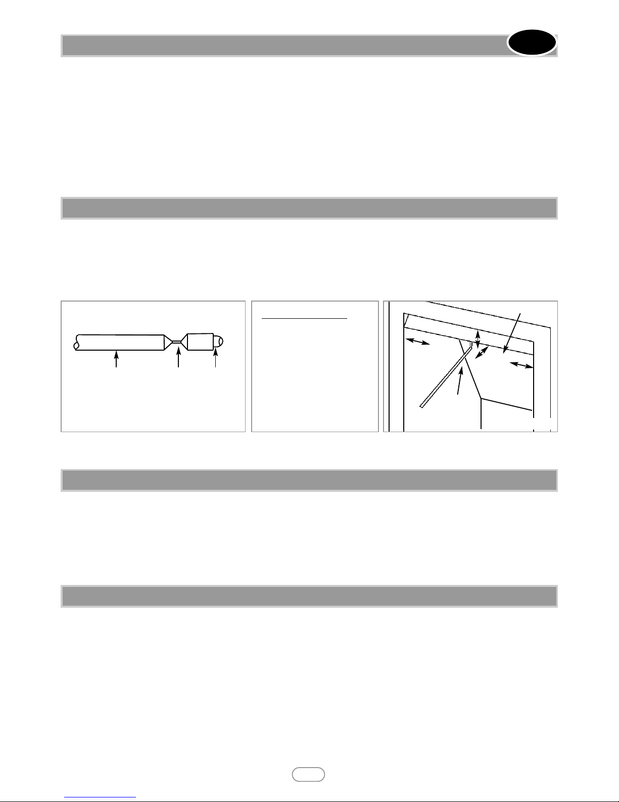
Close all doors and windows to the room containing the appliance. Let the fire run on HIGH for five minutes. Take a smoke match,
light it, and using a smoke match tube, hold it at the top edge of the fire opening, 25mm down and 25mm in. Starting 50mm in
from either side, run the smoke match across the opening. All the smoke should be drawn away up the flue. Any smoke returning into the room indicates that spillage is occurring. If the initial spillage test fails, run the fire for a further 10 minutes and repeat
the test. When the test has been completed satisfactorily, repeat with any extractor fans in the premises running on the highest
setting, and any communicating doors open. Finally, repeat with all doors open.
NOTE: If spillage is still indicated after undertaking all of the above, there may be a fault in the flue, or insufficient ventilation is present. If the problem cannot be rectified immediately, then expert advice should be sought. Inform the user, discon-
nect the fire, and attach an explanatory label.
All instructions must be handed to the user for safekeeping. Show the customer how to light and control the fire.
After commissioning the appliance, the customer should be instructed on the safe use of the appliance and the need for regular
servicing. Frequency of service depends on usage, but MUST be carried out at least once annually.
Scratched and other superficial damage to the matt black paintwork of the appliance can be covered with matching heatproof
spray. Use only the manufacturers’ recommended spray paint. Paint only when the fire is OFF and cold. Always mask off the surrounding area to prevent contamination with overspray. Ventilate the room during the use of the spray.
DO NOT attempt to spray paint the coals or ceramics, or wash them in water.
Ensure that the fire is fully cold before attempting service. A suggested procedure for servicing is detailed below.
1. Lay out the dust sheet and tools.
2. Carefully remove the firefront casting, and ceramic components.
3. Check around the top of the fireplace opening for signs signs of spillage.
4. Isolate the gas supply at the appliance inlet elbow, and disconnect the gas supply pipe. Remove the two screws
securing the tray to the front support.
5. Lift the burner tray from the chair brick.
6. Check the flue with smoke pellet for correct operation.
7. Strip off the burner pipes and clean thoroughly.
8. Clean out the injector and pilot assembly. DO NOT attempt to dismantle the pilot unit.
9. Ensure the injector is aligned squarely with the venturi tube. Re-assemble and re-fit the burner tray.
10. Re fit and replace the ceramics, using genuine spares where necessary.
11. Re-fit the decorative front.
12.2 FLUE SPILLAGE MONITORING SYSTEM
GB IE
12.3 TESTING FOR SPILLAGE
Match
Crimp
Tube
Figure 5 : Cross section of smoke match tube
Make a smoke match tube from 10mm diameter
tube. Seal off one end and crimp the tube to prevent the smoke match from sliding down inside.
Spillage test - Figure 6
A.25mm down from top of
opening
B. 25mm in from front of
opening.
C. Disregard outer 50mm
either side of fireplace
opening
C
C
B
A
Fireplace Opening
Smoke Match
In Tube
Figure 6
12.4 BRIEFING THE CUSTOMER
13.0 SERVICING
Page 7

12. Turn on the gas supply, and leak test.
13. Check any purpose provided ventilation is un-obstructed.
14. Light the fire and test for spillage.
15. Check setting pressure and safe operation of the appliance.
For specific servicing instructions, see the relevant sections.
Remove the firefront and place to one side. Remove the ceramic components. Gently clean in the open air. Be careful not to
create dust from the coals. Where necessary replace damaged components with genuine spares. Seal scrap components in plastic bags and dispose of at proper refuse sites as directed. Re-fit the ceramics carefully by referring to the relevant section of the
user instructions.
Remove the tray as previously described. The pilot unit can be removed by undoing the tubing nut, the thermocouple nut on
the rear of the valve, lint arrestor, two securing screws, and lifting away. Remove the tubing nut from the valve end of the pilot
pipe, and blow through to dislodge any debris that may be present. Clean the exterior of the pilot assembly with a soft brush
and blow through the flame ports on the pilot head. Check the aeration holes are free from lint or dirt. The pilot assembly is a
non-serviceable item, and should not be taken apart. The aeration hole must be absolutely clear internally for proper operation.
A thoroughly cleaned (inside and out) oxypilot will cure a wide range of ignition faults. Remove the two tubing nuts on the
ends of the gas pipe to the injector elbow. Release the screw through the supporting leg and lift assembly clear. The injector
pipe can now be checked for debris. Remove the nut retaining the injector elbow. Blow through the elbow to remove any
debris.
The valve is not field serviceable, apart from the pilot filter. Remove the control knob by pulling it forwards, then remove the
largest of the three screws on the face of the valve. Slide the filter out and clean away any debris that may have accumulated. The
filter element should also be blown clean. This component should not require replacement, however if signs of deterioration are
evident then a genuine spare must be used. If a large amount of debris is present in the filter then the pipework and control should
be thoroughly cleaned before re-assembly.
Fire sparks but pilot does not light No gas to fire, check isolators are open.
Pipework blockage, clean out.
Air not fully purged, re-purge supply or wait longer.
Spark earthing to metal work, reset gap correctly.
Blocked pilot, clean out internally.
Pilot lights but then goes out Severe restriction in gas supply, clear obstruction.
Faulty thermocouple, replace pilot unit.
Hold control knob in for longer.
Fire does not spark at pilot HT lead detached, refit.
Spark gap too large or small, reset correctly.
Faulty piezo unit, replace.
Debris shorting out electrode, clean.
Fire runs for a time and then cuts off Excessive room draught or flue pull, rectify.
Loose or faulty thermocouple, rectify.
ODS system in operation.
Firebox grommet seal not fitted, rectify.
Lint in pilot aeration hole, clean thoroughly internally
Pilot flame shrinks when fire is on high Poor gas flow to fire, check pressure with fire on high.
If pressure is low, remove any restriction in pipework or valve.
Check all isolators are adequately sized and fully open.
Check meter pressure is adequate.
Air leak under base of firebox, rectify.
Lint in pilot aeration hole, clean thoroughly internally.
Fire smells when first lit or in use Newness smell from brand new appliance.
Spillage occurring. Carry out spillage test and rectify any problems.
Low temperature sealants or combustible materials used in incorrect positions.
13.0 SERVICING - CONTINUED
GB IE
© 2010 Focal Point Fires plc.
7
13.1 CLEANING THE CERAMICS
13.2 DISMANTLING THE BURNER UNIT
14.0 TROUBLESHOOTING GUIDE
Page 8

• The installation and Servicing of this fire MUST only be carried out by a competent person in accordance with local Codes
and/or Regulations, Building Regulations and the manufacturer's instructions. Failure to comply with these could lead to prosecution and invalidate the appliance warranty. In the event of gas leakage from the appliance, the gas supply must be turned off
at the nearest isolating valve. This appliance is only suitable for the gas type for which it is supplied.
• Keep a note of the installer's name and address, GAS SAFE registration number and the original purchase receipt and the date
of installation. Failure to produce this information may invalidate the warranty. The appliance should be serviced regularly to
ensure continued safe operation. See the servicing section for further reference.
• Parts of this appliance become naturally hot during use. It is recommended that a suitable fireguard is used, especially where
young children, pets, the elderly or infirm are concerned. The manufacturer of this appliance considers all surfaces as working
surfaces with the exception of the control knob and control panel.
• It is recommended that a suitable fireguard conforming to BS 8423 is used, especially where young children, the elderly, or
infirm are concerned.
• The appliance should be serviced regularly to ensure continued safe operation. Frequency of service will depend on use, but
MUST be carried out at least once annually.
• Combustible items, such as flooring and furniture and soft wall coverings (such as blown vinyl or embossed paper), low temperature surrounds etc may discolour if fitted too close to the fire. See relevant section for further details on clearances to
combustibles. No combustible materials or flooring should protrude onto the hearth.
• This appliance incorporates a combustion monitoring system (ODS).
• DO NOT burn any foreign material on this fire, the coals must be of the correct type and laid out in accordance with the rel-
evant section of these instructions. Failure to do so could create a hazard or lead to sooting.
• The fire is only suitable for use with the gas type for which it is supplied.
• This appliance is fitted with a flue blockage safety device which will shut down the fire if abnormal flue conditions occur. It is
NOT a substitute for an independently mounted Carbon Monoxide detector.
• This fire is supplied with a particular style of firefront. Use of the firefront will ensure an adequate airflow under the firebed
for the correct functioning of this appliance. Use ONLY the firefront supplied with the appliance. Use of any other firefront
could be dangerous.
USER INSTRUCTIONS
2.0 CLEARANCES TO COMBUSTIBLES
Section Content Page No
1.0 Important Notes 1
2.0 Clearances to Combustibles 1
3.0 Ventilation 2
4.0 Operating Instructions 2
5.0 Flue Spillage Monitoring System 2
6.0 Fuel Bed Layout 2
7.0 Cleaning 4
8.0 List of Replacement Parts 4
9.0 Installation Details 5
10.0 Service History 5
A combustible shelf may be fixed to the wall above the fire, providing that it complies with the dimensions given below.
A non-combustible shelf may be fitted to within 10mm of the top edge of the fireplace opening.
Combustible materials, such as wood, may be fitted to within 100mm of either side of the fireplace opening, providing the forward projection does not exceed 100mm.
Any combustible side walls must be at least 500mm to the side of the radiant heat source.
As with all heating appliances, any decorations, soft furnishings, and wall coverings (i.e. flock, blown vinyl and embossed paper)
positioned too close to the appliance may discolour or scorch.
1.0 IMPORTANT NOTES
1
© 2010 Focal Point Fires plc.
GB IE
Maximum depth of shelf Minimum distance from finished hearth
surface to underside of shelf
100mm 745mm
150mm 845mm
203mm 895mm
Page 9
No purpose provided ventilation is normally required for this appliance. The requirements of other appliances operating in the
same space or room, and the results of a spillage test must be taken into consideration when assessing ventilation requirements,
this will have been carried out by your registered installer.
For Republic of Ireland, ventilation may be required, see IS 813, ICP3, IS 327, and any other rules in force.
WARNING : Ventilation openings (where fitted) must never be blocked or restricted in any way.
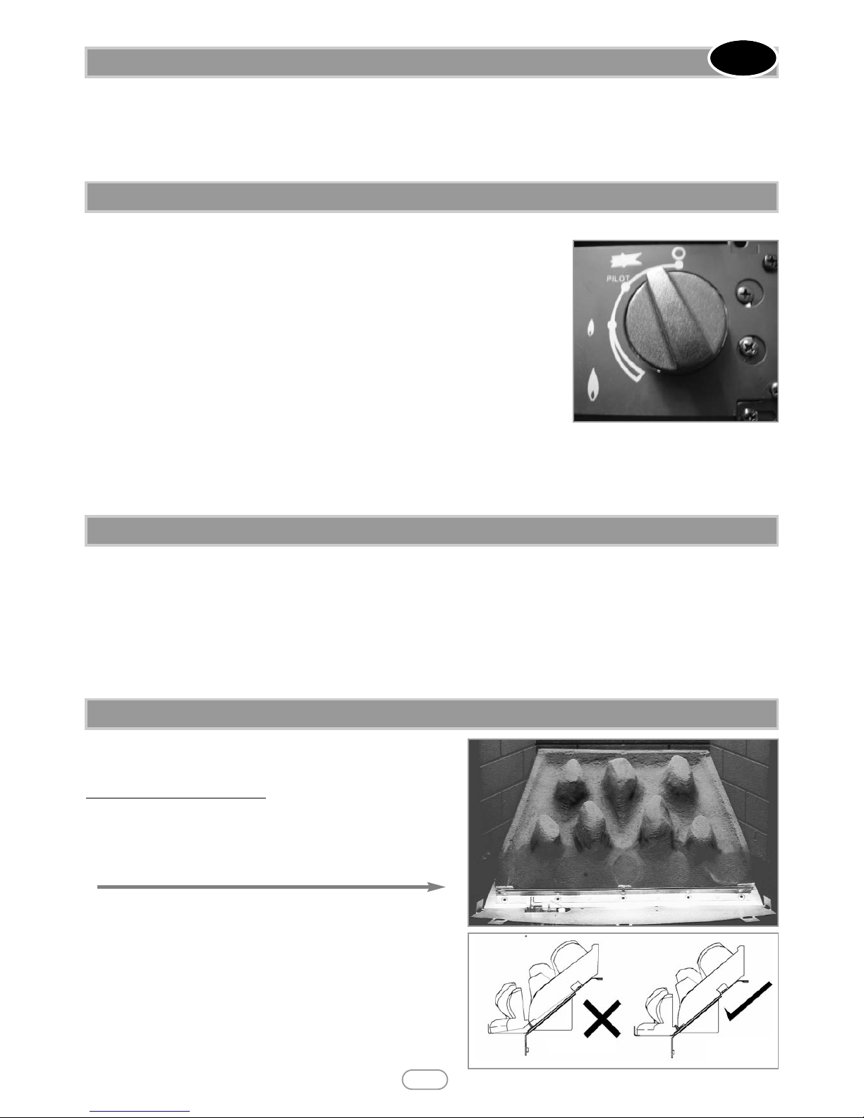
The pilot is visible through the left hand side of the front coal strip. Push in and turn the
control knob to the SPARK position, and hold there for a few seconds.
Continue turning anti-clockwise through the spark click to the PILOT light position,
ensuring the pilot has lit. If not, return the knob clockwise, and repeat.
When the pilot lights after the spark, keep the knob depressed for approximately ten
seconds. Now release the knob and the pilot should stay alight. If not, retry ignition. If the
pilot is extinguished during use, wait three minutes before repeating the ignition procedure.
To achieve the HIGH setting, push the control knob in slightly and continue turning anticlockwise to the high (large flame) position. The main burner should light after a few seconds.
To decrease the setting to LOW, turn the control knob clockwise to the low setting. To turn to the PILOT position from the
HIGH or LOW positions, press the control knob in, and return to the pilot position and release. To turn the fire OFF, keep the
knob pressed in, return to the off position and release.
A safety interlock prevents re-ignition of the pilot flame until the thermocouple has cooled sufficiently to allow the magnetic valve
unit to reset itself.
This fire is fitted with a flue spillage safety device (ODS).
If the fire shuts down during use for no apparent reason then several reasons may be suspected. If a door or window has been
opened creating a draught, then pilot disturbance could be the problem, and removal of the draught should resolve this. The fire
can then be re-lit in accordance with the previous section.
If pilot disturbance is not the cause, then the ODS safety system may be in operation. Switch the appliance OFF, call in your
installer to check any ventilation and carry out any remedial work required. DO NOT allow the appliance to be used until the
installation is passed as safe.
Full depth coal effect models
1. Position the combustion matrix onto the burner tray as shown in
figure 2. The front edge of the matrix should sit snugly behind the
back edge of the burner rails as shown in figure 3. Do not fit the
matrix on top of the burner rails.
4.0 OPERATING THE APPLIANCE
3.0 VENTILATION
2
© 2010 Focal Point Fires plc.
5.0 FLUE SPILLAGE MONITORING SYSTEM
6.0 FUEL BED LAYOUT
GB IE
Figure 1
Figure 2
Figure 3
Correct
Incorrect
Page 10
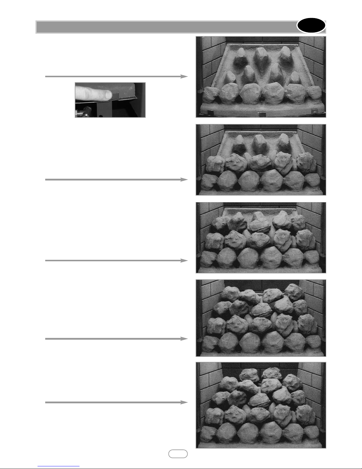
2. Position the front coal strip as shown in figure 4. The rear edge of
the front coal strip should fit in front of the burner rail. Again, do not
place on top of the burner rails. When the front coal is in position
bend up the three metal tags at the front of the tray to retain as
shown in figure 4.
3. Coals. All of the coals are the same. Take five coals and place them
as shown in figure 5. Care should be taken to ensure that the coals
bridge the gap between the front coal and the four coal supports at
the front of the matrix. Care should also be taken not to push the
coals right down between the coal supports, as this can detract from
the flame picture when the appliance is running.
4. Take five more moulded coals and position as shown in figure 6 to
form the ‘second row’ of the fuel effect. The coals may be rotated as
desired to fit into the gaps between the coal supports in order to
create a random, realistic effect. Again, remember not to push the
coals down too far into the valleys between the coal supports as this
can have a detrimental effect to the flame picture.
5. Take another four coals and place behind the second row of coals
as shown in figure 7, in order to complete the third row. The coals
may be orientated as desired to achieve a realistic effect. Keep the
spacing between the coals even and uniform. The two coals at the
ends of the row may be placed rearwards, towards the back corners
of the fuel matrix.
6. Finally, take the two remaining coals and place at the back of the
fuel matrix, in the centre as shown in figure 8. Adding these coals
should complete the appearance of the fuel bed giving an even distribution of equally spaced coals.
IMPORTANT : The fire is designed to operate correctly
with the coals supplied when assembled according to the
instructions. Never add to the sixteen coals, or change
them for a different type. Never throw rubbish or other
matter onto the coal bed.
6.0 FUEL BED LAYOUT - CONTINUED
3
© 2010 Focal Point Fires plc.
GB IE
Figure 4
Figure 4
Figure 5
Figure 6
Figure 7
Figure 8
Page 11

Before carrying out any of the following operations, ensure that the fire is OFF and completely cold.
FIREFRONT - Any dust accumulating in the firefront may be removed using a vacuum cleaner or dry cloth. Heavy stains may be
removed by using a damp cloth and mild household detergent. Brass parts of the firefront may be cleaned using a suitable brass
cleaner. Replace the front centrally against the fire after cleaning. Do not use a damp cloth to clean cast iron fronts.
PAINTED AREAS - These can be cleaned using a dry cloth.
COALS AND CERAMICS - Remove the firefront and place to one side. Remove the ceramic components. Gently clean in the
open air. Be careful not to create dust from the coals. Where necessary replace damaged components with genuine spares. Seal
scrap components in plastic bags and dispose of at proper refuse sites as directed.
Re-fit the ceramics carefully by referring to the relevant section of these instructions.
7.0 CLEANING
GB IE
4
© 2010 Focal Point Fires plc.
8.0 LIST OF REPLACEMENT PARTS
Hannington - All models
Item Part number
Burner assembly - complete TRAY014
Firefront - brass F800045
Firefront - black F800048
Main gas valve F730066
ODS F730006
Injector F730046
Ceramic coal matrix F780007
Front coal strip F780008
Pack of 16 Coals F550038
Page 12
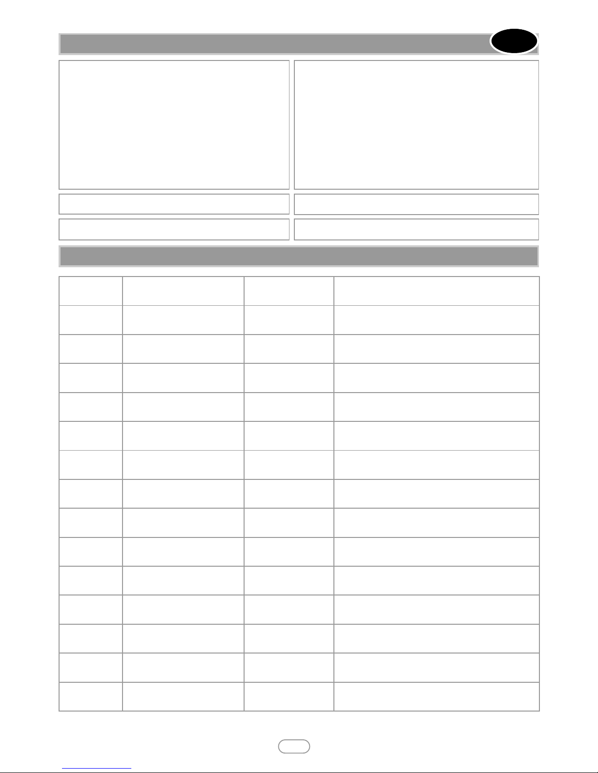
9.0 INSTALLATION DETAILS
Installer GAS SAFE registration No :
Model :
Fire serial No. :
Name & contact details of installer :
Supplied by :
10.0 SERVICE HISTORY
As our policy is one of continuous improvement and development , we hope therefore you will understand we must retain the right to amend details and/or specifications without prior notice.
5
© 2010 Focal Point Fires plc.
F861015
GB IE
Note : Gas SafeTMregistered operatives are the only class of person considered as competent by the HSE under the Gas Safety (Installation and Use) Regulations 1998.
Date installed :
Date of service Serviced by (name): GAS SAFE No. : Contact details of Engineer
 Loading...