

Page 1
1
FOR USE ONLY WITH DECORATIVE TYPE
UNVENTED ROOM HEATERS.
Do not store or use gasoline or other flammable
vapors or liquids in the vicinity of this or any other
appliance.
WHAT TO DO IF YOU SMELL GAS
• DO NOT light any appliance.
• DO NOT touch any electrical switches.
• DO NOT use any phone in your building.
• Immediately call your gas supplier from a neighbor’s
phone.
Follow your gas suppliers instructions.
• If your gas supplier cannot be reached, call the fire
department.
Installation and service must be performed by a
qualified installer, service agency or the gas supplier.
WARNING: IF THE INFORMATION IN THIS MANUAL
IS NOT FOLLOWED EXACTLY, A FIRE OR
EXPLOSION MAY RESULT CAUSING PROPERTY
DAMAGE, PERSONAL INJURY OR LOSS OF LIFE.
UNVENTED WALL MOUNTED ROOM HEATERS
INSTALLATION INSTRUCTIONS
(Para Instrucciones en español, ver la página 13)
Installer And Consumer Are
To Retain The Appliance
Manual With The Installed
Appliance
WARNING: IMPROPER INSTALLATION, ADJUSTMENT,
ALTERATION, SERVICE OR MAINTENANCE CAN CAUSE
INJURY OR PROPERTY DAMAGE. REFER TO THIS
MANUAL. FOR ASSISTANCE OR ADDITIONAL
INFORMATION CONSULT A QUALIFIED INSTALLER,
SERVICE AGENCY OR THE GAS SUPPLIER.
WARNING: DO NOT BUILD A WOOD FIRE. DO NOT
BURN WOOD OR OTHER MATERIAL IN THESE
APPLIANCES.
This is an unvented gas-fired heater. It uses air
(oxygen) from the room in which it is installed.
Provisions for adequate combustion and ventilation air
must be provided. Refer to Combustion and Ventilation
Air Section, Page 3.
This appliance may be installed in an aftermarket,
permanently located, manufactured (mobile) home,
where not prohibited by local codes.
The appliance is only for use with the type of gas
indicated on the rating plate. This appliance is not
convertible for use with other gases.
Issue C - 15/06
INSTALLER:
LEAVE THIS MANUAL WITH THE APPLIANCE.
CONSUMER:
RETAIN THIS MANUAL FOR FUTURE REFERENCE.
Due to high temperatures, the appliance should be
located out of traffic and away from furniture or
draperies. Do not place clothing or other materials on or
near this appliance.
MODEL : F500079
REFLECTION
MODEL : F500083
NEON
MODEL : F500082
ATHOS
MODEL : F500081
SCANDIUM
317-S-03-5 (Reflection)
317-S-07-5 (Neon)
317-S-06-5 (Athos)
317-S-05-5 (Scandium)
Report No’s :
Page 2
This appliance is a high efficiency, unvented, flame effect gas heater. It
provides radiant and convected warmth both efficiently and safely
utilizing the latest type catalytic convertor burner technology. The
appliance does not require a flue system of any type as the catalytic
converter cleans the flue products to provide a complete combustion
system, which is intrinsically safe.
These heaters are fitted with a specially designed pilot utilizing an
oxygen depletion sensor (ODS) which responds to the amount of
oxygen available in the room and shuts the heater off before the oxygen
level drops below 18%. The pilot can be relit only when fresh air is
available. Refer to the Combustion and Ventilation Air section.
The appliance is designed to fit various types of situations as listed in
the Installation Requirements.
This appliance is factory set for operation on the gas type, and at the
pressure stated on the appliance rating plate.
On initial light up of a new appliance, the ‘newness’ will burn off within
the first few hours of operation. During this period some smoke may be
emitted from outlet grille, this should be no cause for concern.
Accordingly, the room should be well ventilated with all windows and
doors open during this period.
Read all these instructions before commencing installation.
All instructions must be handed to the user for safekeeping.
QUANTITY DESCRIPTION
1 Firebox and burner assembly
1 Installation and operating instructions
1 Glass facia panel assembly (Scandium & Neon models)
1 Aluminium frame assembly (Athos & Reflection models)
1 Rear frame assembly (Neon & Reflection models)
1 Fitting template
1 Screw and wall plug pack
1 Rubber grommet
STATE OF MASSACHUSETTS: THE INSTALLATION MUST BE MADE
BY A LICENSED PLUMBER OR GAS FITTER IN THE
COMMONWEALTH OF MASSACHUSETTS.
Carbon Monoxide Poisoning: Early signs of carbon monoxide
poisoning are similar to the flu with headaches, dizziness and/or
nausea. If you have these signs, obtain fresh air immediately. Turn off
the gas supply to the appliance and have it serviced by a qualified
2
WARNING: FAILURE TO COMPLY WITH THE INSTALLATION
AND OPERATING INSTRUCTIONS PROVIDED IN THIS
DOCUMENT WILL RESULT IN AN IMPROPERLY INSTALLED
AND OPERATING APPLIANCE, VOIDING ITS WARRANTY.
ANY CHANGE TO THIS APPLIANCE AND/OR ITS
OPERATING CONTROLS IS DANGEROUS. IMPROPER
INSTALLATION OR USE OF THIS APPLIANCE CAN CAUSE
SERIOUS INJURY OR DEATH FROM FIRE, BURNS,
EXPLOSION OR CARBON MONOXIDE POISONING.
1.0 GENERAL INFORMATION
2.0 INVENTORY
4.0 IMPORTANT SAFETY INFORMATION
TABLE OF CONTENTS
3.0 APPLIANCE DATA
Gas Type Natural Gas
Gas inlet pressure Maximum 10.5” w.c.
Minimum 6” w.c.
Regulator Pressure Setting 5” w.c.
Max Energy Input
11,950 BTU/hr
Min Energy Input
6,820 BTU/hr
Pilot Energy Input 560 BTU/hour
Burner (Manifold) Pressure High 2.5” w.c. (+/-0.3” w.c.) Hot
2.4” w.c. (+/-0.3” w.c.) Cold
Low 0.8” w.c. (+/-0.3” w.c.) Hot
0.8” w.c. (+/-0.3” w.c.) Cold
Main burner flow restrictor Stereo 2.0mm (1/4” BSP)
Oxypilot SIT/Bray 9082
Gas Inlet Connection 3/8” NPT at regulator
Ignition Piezo spark
Spark Gap 1/8” - 3/16”
Please see Data Plate affixed to appliance for current data.
This appliance is for use only with the gas type, and at the pressure
stated on the appliance Data Plate.
IMPORTANT: READ AND UNDERSTAND THESE
INSTRUCTIONS COMPLETELY BEFORE INSTALLING OR
OPERATING YOUR UNVENTED ROOM HEATER.
WARNING: FAILURE TO KEEP THE PRIMARY AIR
OPENING(S) OF THE BURNER(S) CLEAN MAY RESULT IN
SOOTING AND PROPERTY DAMAGE.
Section Contents Page No.
1.0 General Information 2
2.0 Inventory 2
3.0 Appliance Data 2
4.0 Important Safety Information 2
5.0 Codes 3
6.0 Combustion and Ventilation Air 3
7.0 Site Requirements 4
8.0 Preparing the Appliance 5
9.0 Mounting the Appliance 5
10.0 Checking the Burner 6
11.0 Connecting a Gas Line 6
12.0 Checking the Gas Connections 6
13.0 Gas Pressure Check 6
14.0 Spark Gap 7
15.0 Final fitting of the frame assembly 7
16.0 Fitting the side panels 7
17.0 Briefing the customer 8
18.0 Servicing 8
19.0 Servicing the Burner 8
20.0 Pilot Assembly 8
21.0 Catalysts 9
22.0 Testing for Firebox Leakage 9
23.0 Cleaning 9
24.0 Lighting Instructions 10
25.0 To Turn off gas to Appliance 10
26.0 Troubleshooting Guide 11
27.0 Shortlist of Spare Parts 11
28.0 Positioning of field assembled parts 12
Page 3

• Children and adults should be alerted to the hazard of high surface
temperature and should stay away to avoid burns or clothing ignition.
• Young children should be carefully supervised when they are in the
same room with the heater.
• Do not place clothing or other flammable material on or near the
heater.
• Any safety screen or guard removed for servicing the heater must be
replaced prior to operating the heater.
• Installation and repair should be done by a qualified service person.
The heater should be inspected before use and at least annually by a
professional service person. More frequent cleaning may be required
due to excessive lint from carpeting, bedding material, etc. It is
important that control compartments, burners and circulating air
passageways of the heater be kept clean.
• Allow the heater to cool before servicing. Always shut off the gas to
the heater while performing service work.
• The installation must conform with local codes or, in the absence of
local codes with the National Fuel Gas Code, ANSI Z223.1.
• The heater and its individual shut-off valve must be disconnected
from the gas supply piping system while performing any tests of the
gas supply piping system at pressures in excess of 1/2 psig.
• The heater must be isolated from the gas supply piping system by
closing its individual manual shut-off valve during any pressure
testing of the gas supply piping system at test pressures equal to or
less than 1/2 psig.
• Keep heater area clear and free from combustible materials, gasoline
and other flammable vapors and liquids.
• Do not use this heater if any part has been under water. Immediately
call a qualified service technician to inspect the room heater and to
replace any part of the control system and any gas control which has
been under water.
• Input ratings are shown in BTU per hour and are for elevations up to
4,800 feet. Do not install this heater at an elevation above 4,800 feet if
the gas supply has not been derated for that elevation. Consult your
local gas supplier. (For operation at elevations above 4,800 feet,
equipment ratings shall be reduced at the rate of 4 percent for each
1,000 feet above sea level before selecting appropriately sized
equipment.)
• Ensure that the heater is clean when operating. Excessive dust
accumulation on the burner will increase the amount of carbon
monoxide formation and could lead to carbon monoxide poisoning
and/or death.
• This appliance is intended for supplemental heating
Adhere to all local codes or in their absence the latest edition of The
National Fuel Gas Code ANSI Z223.1 or NFPA54 which can be obtained
from The American National Standards Institute, Inc. (1430 Broadway, New
York, NY, 10018) or National Fire Protection Association, Inc.
(Batterymarch Park, Quincy, MA, 02269).
Seller of unvented propane or natural gas fired supplemental room heaters
shall provide to each purchaser a copy of 527 CMR 30 upon sale of the
unit.
This Focal Point Unvented Gas Room Heater is certified by OMNI-Test
Laboratories, Inc to ANSI Z21.11.2-2004b standard.
This heater shall not be installed in a confined space or unusually tight
construction unless provisions are provided for adequate combustion and
ventilation air.
The National Fuel Gas Code, ANSI Z223.1/NFPA 54 defines a confined
space as a space whose volume is less than 50 ft 3per 1,000 BTU/Hr (4.8
m3per kW) of the aggregate input rating of all appliances installed in that
space and an unconfined space as a space whose volume is not less than
50 ft 3per 1,000 BTU/Hr (4.8 m3per kW) of the aggregate input rating of all
appliances installed in that space.
Rooms communicating directly with the space in which the appliances are
installed, through openings not furnished with doors, are considered a part
of the unconfined space.
Unusually tight construction is defined as construction where:
a. wall and ceilings exposed to the outside atmosphere have a continuous
water vapor retarder with a rating of one perm or less with openings
gasketed or sealed, and
b. weather stripping has been added on operable windows and doors, and
c. caulking or sealants are applied to areas such as joints around window
and door frames, between sole plates and floors, between wallceiling joints,
between wall panels, at penetrations for plumbing, electrical, and gas lines,
and at other openings.
Use the following equations to determine if you have a confined or
unconfined space.
3
5.0 CODES
6.0 COMBUSTION AND VENTILATION AIR4.0 IMPORTANT SAFETY INFORMATION (continued)
Determine the volume of space — ft 3.
Length x Width x Height = _____ ft
3
(Include adjoining rooms with doorless passageways or ventilation
grills between rooms.)
Example: 24' (L) x 16' (W) x 8' (H) = 3072 ft
3
Divide the volume of space by 50 ft 3to determine the maximum
BTU/Hr the space can support.
______ (volume of space – ft
3
)/ 50 ft 3=
(Maximum BTU/Hr the space can support)
Example: 3072 ft 3 / 50 ft 3 = 61.44
or 61,440 BTU/Hr the space can support.
Add the BTU/Hr of all the fuel burning appliances in the space.
Vent-Free heater _______ BTU/Hr
Gas appliance #1* _______ BTU/Hr
Gas appliance #2 + _______ BTU/Hr
Gas appliance #3 + _______ BTU/Hr
Total = _______ BTU/Hr
Example:
Vent-free heater #1 12,000 BTU/Hr
Vent-free heater #2 20,000 BTU/Hr
Gas appliance #1 35,000 BTU/Hr
(water heater)
Total = 67,000 BTU/Hr
* Do not include direct-vent gas appliances. Direct-vent is sealed
combustion and draws combustion air from the outdoors.
1.
2.
3.
Page 4
The space in the previous example is a confined space because the actual
BTU/Hr used is more than the maximum BTU/Hr the space can support.
You must provide additional fresh air.
Your options are:
a. Rework equations adding the space of adjoining room(s). If the extra
volume provides an unconfined space, then remove door or add ventilation
grills between rooms. Refer to National Fuel Gas Code, ANSI Z223.1,
Section 5.3.
b.
Vent room directly to the outdoors. Refer to National Fuel Gas Code,
ANSI Z223.1, Section 5.3.
c. Install a lower BTU/Hr heater, to make the area an unconfined space.
If the actual BTU/Hr used is less than the maximum BTU/Hr the space can
support, then the space is an unconfined space. You will need no additional
fresh air ventilation for an unconfined space.
This appliance is designed to be wall-hung. Do not recess any part
of the appliance into the wall.
This Appliance may be installed in any room in a home except bathrooms
and bedrooms - or areas where large amounts of steam are likely to be
generated.
Installation in living rooms is common, however other rooms such as
kitchens, dining rooms and hallways are permitted, providing a suitable
natural gas supply is available, and rooms sizing and ventilation
requirements are strictly adhered to (see section 6).
The appliance is designed to be versatile, and as such will operate correctly
when exposed to normal gentle draughts experienced within the home. It is
not recommended, however that the appliance be installed in areas where
it is likely to be exposed to persistent strong draughts, that may be
generated by outside doors or windows, air vents etc. It is recommended
that the appliance should not be installed within 20” of any air vent.
Clearances to non-combustibles
Non-combustible surfaces are defined as brick, metal, marble, concrete
etc. and also a number of man-made materials impervious to flame. If in
doubt refer to the material manufacturer for further information before
proceeding with installation.
Clearances to the sides of the appliance are 4”. Clearance to the front of
the appliance is 20”.
The back of the appliance may be installed directly onto a non-combustible
wall, providing the area behind the appliance is flat and does not interfere
with the various vent holes in the back panel of the appliance.
The appliance may be installed with or without a non-combustible hearth. If
a hearth is fitted, the size and design may be as desired.
A non-combustible shelf of any depth may be positioned above the
appliance provided it is no closer than 16” from the top of the appliance
glass panel and the wall above the appliance is non combustible.
Clearances to combustible materials
Combustible materials are defined as wood, fabrics, or other materials
likely to combust if exposed to flame. Generally, any material, which is likely
to discolour, melt or misshape when exposed to moderate heat, should be
considered as a combustible material or surface.
Clearance to the sides of the appliance are 4” but curtains, drapes and
other fabrics are not permitted within a distance of 20” of the appliance
sides. No such materials are permitted directly above the appliance
regardless of distance.
The minimum clearance to the ceiling above the appliance is 32” measured
from the top of the appliance glass panel.
Combustible materials should not be positioned directly in front of the
appliance within a distance of 40”.
Under no circumstances should any electrical equipment e.g. plasma
screen TV sets etc. be positioned on the wall above the appliance. The
appliance is designed to be wall mounted alone and not in conjunction with
any type of combustible fire surround. No combustible shelves should be
positioned on the wall above the appliance. It should be established that
any mirrors or picture frames etc. to be positioned on the wall above the
appliance are able to withstand prolonged exposure to moderate heat and
moisture before proceeding with their installation.
The back of the appliance may be installed directly onto a combustible wall,
providing it is relatively flat and does not interfere with the various vent
holes in the back panel of the appliance. The wall must be structurally
sound and constructed from a material capable of withstanding moderate
heat. Finished plaster, conventional wall paper and dry-lined plasterboard
are examples of suitable materials. Materials such as flock, blown vinyl and
embossed paper which are sensitive to even small amounts of heat should
be avoided as scorching and or discoloration may occur over time.
If the appliance is to be mounted on a dry-lined wall or a timber framed
construction wall then the integrity and ability of the wall to carry the weight
of the appliance must be confirmed. It is important in these circumstances
that any vapor control barrier is not damaged, and that any structural
members of the house frame are not damaged.
The appliance may be positioned as close to a solid floor (i.e. stone,
wooden laminate etc.) as the particular design of fire frame permits,
however it is not permitted to install the appliance within 4” of carpet, rugs
or fabric materials of any kind. This dimension is measured vertically to the
bottom of the appliance frame.
4
6.0 COMBUSTION AND VENTILATION AIR - continued
WARNING: IF THE AREA IN WHICH THE HEATER MAY BE
OPERATED IS SMALLER THAN THAT DEFINED AS AN
UNCONFINED SPACE OR IF THE BUILDING IS OF
UNUSUALLY TIGHT CONSTRUCTION, PROVIDE ADEQUATE
COMBUSTION AND VENTILATION AIR BY ONE OF THE
METHODS DESCRIBED IN THE NATIONAL FUEL GAS CODE,
ANSI Z223.1/NFPA54, SECTION 5.3 OR APPLICABLE LOCAL
CODES.
7.0 SITE REQUIREMENTS
4.
Compare the maximum BTU/Hr the space can support with the
actual amount of BTU/Hr used.
_______ BTU/Hr (max. the space can support)
_______ BTU/Hr (actual amount of BTU/Hr used)
Example:
61,440 BTU/Hr (max. the space can support)
67,000 BTU/Hr (actual amount of BTU/Hr used)
WARNING: DO NOT USE A BLOWER INSERT, HEAT
EXCHANGER INSERT OR OTHER ACCESSORY NOT
APPROVED FOR USE WITH THIS HEATER.
Page 5
5
Gas connection :
The
heater gas inlet
connection is 3/8”
NPT at the regulator,
located below the
burner, in the center of
the heater.
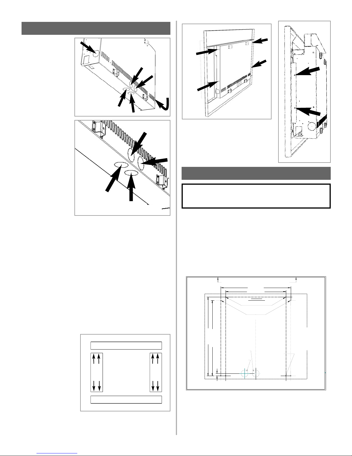
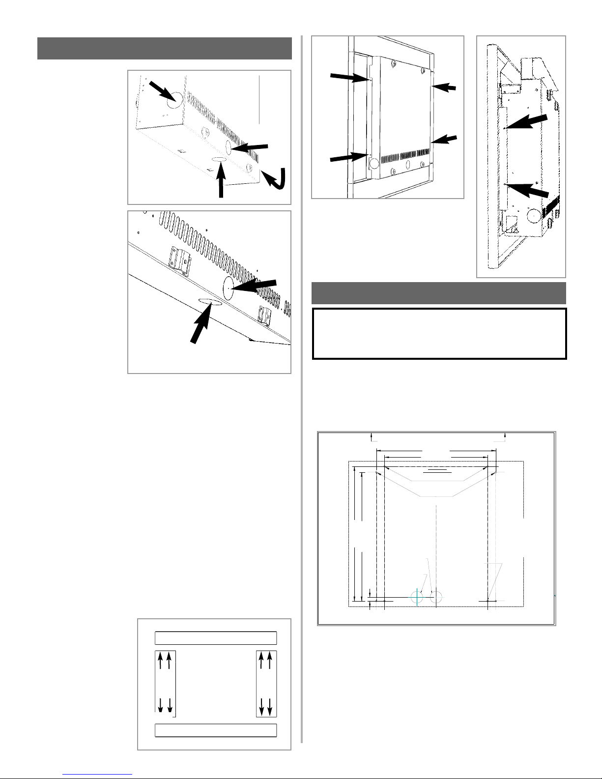
Reflection models :
There are six possible
entry points for the gas
supply pipework to
enter the appliance
firebox. These entry
points are ‘knock out’
type holes (shown in
figure 1).
Neon, Athos and
Scandium models :
There are four possible
entry points for the gas
supply pipework to
enter the appliance
firebox. These entry
points are ‘knock out’
type holes (shown in
figure 2).
Non-concealed gas
connections may be
made using the entry
points on the base of the firebox. A concealed gas connection may be
made using the knock out hole in the centre back of the firebox. Select the
most appropriate entry point and knock out the relevant hole.
If a concealed gas connection is to be made, the supply pipe should always
be sleeved through walls and floors using the shortest possible route.
For concealed supply pipe routing, pipes must (where possible) be vertical
and providing there is sufficient wall thickness available, they should be
placed in pipe chases. Horizontal pipe runs should be avoided. Prior to
chasing a solid wall, an inspection should be made to note the proximity of
any cables/sockets outlets which may already be buried. Pipes must be
secured using suitable clips and protected against corrosion. Ideally factory
finished protected pipework and fittings should be used. Joints should be
kept to a minimum and compression fittings must not be used. The
pipework installation must be tested for soundness before any protection is
applied and/or the pipework and fittings are buried.
Reflection models ; At
this stage it is necessary
to assemble the rear
frame of the appliance.
Unpack the four frame
sections and lay face
down on a soft surface
taking care not to
damage the painted
finish. Using the eight no.
8 self tapping screws
provided, fix the frame
pieces together as
shown in figure 3, making sure that the edges align neatly. Fit the rear
frame to the firebox as shown in figure 4.The decorative front frame
assembly is fitted after the main firebox has been fitted to the wall.
Neon models : At this stage it is necessary
to assemble the rear frame of the appliance.
The rear frame is attached to the firebox
using four self tapping screws (two each
side) as shown in figure 5.
After having selected the final mounting position of the appliance, taking into account the site requirements as specified in section 7 of these
instructions, the integrity of the wall, and the feasibility of the proposed
supply pipe routing, the firebox of appliance may be secured to the
wall. A full size fitting template is supplied to assist with this.
Mark the positions on the wall as shown as relevant to the particular
model. If the appliance is to be mounted on the inner leaf of a conventional cavity wall, or a solid wall, drill four holes using a 1/4”
masonry bit. Insert the fiber wall plugs provided.
If the appliance is to be mounted on a dry lined wall or a timber framed
construction wall then special cavity screw fixings will be required
which are not supplied with this product. These should be constructed
from metal and not plastic.
8.0 PREPARING THE APPLIANCE
9.0 MOUNTING THE APPLIANCE
WARNING: DO NOT ALLOW FANS TO BLOW DIRECTLY
INTO THE FIREPLACE. AVOID ANY DRAFTS THAT ALTER
BURNER FLAME PATTERNS.
Figure 3
Figure 5
Figure 6
Figure 1
Reflection models
Figure 2
Neon, Athos, Scandium models
Figure 4
F860033 ISSUE A - 24/4/06
WALL MOUNTED VENT FREE
FITTING TEMPLATE
PLANTILLA PARA LA
INSTALACION DE
CHIMENEAS DE PARED SIN
SALIDA DE HUMOS
IMPORTANT
THIS FIRE IS TO BE WALL HUNG ONLY. DO NOT RECESS OR INSET ANY PART OF THE FIRE.
THIS TEMPLATE IS FOR THE MARKING OF FIXING POINTS ONLY. DO NOT INSTALL THE FIRE WITH THIS TEMPLATE IN PLACE.
IMPORTANTE
ESTE APARATO UNICAMENTE DEBE SER COLGADO EN UNA PARED. NO EMPOTRE NINGUN ELEMENTO DE ESTA CHIMENEA.
ESTA PLANTILLA SIRVE UNICAMENTE PARA MARCAR LOS PUNTOS DE FIJACION. RETIRE LA PLANTILLA ANTES DE COLOCAR LA CHIMENEA.
POSITION SPIRIT LEVEL ALONG THIS EDGE TO LEVEL TEMPLATE BEFORE MARKING OUT WALL
COLOQUE EL NIVEL SOBRE ESTE BORDE PARA NIVELAR LA PLANTILLA ANTES DE MARCAR LA PARED
FOCAL POINT
WALL MOUNTED
CATALYTIC VENT FREE
GAS FIRE RANGE
FITTING TEMPLATE
DO NOT RECESS OR
"
17.2 (437mm)
"
0.5 (13mm)
INSET ANY PART OF
CONCEALED GAS INLET
ENTRADA DE GAS OCULTA
(TODOS LOS MODELOS)
CONCEALED GAS INLET
ENTRADA DE GAS OCULTA
REFLECTION, ATHOS,
NEON, SCANDIUM
"
18 (457mm)
"
16 (406mm)
13.8 (350mm)
FIXING POINTS:
PUNTOS DE SUJECION:
PLASMA, CAPELLA, RADIUM
WHEN MOUNTING PLATE IS NOT USED
SI NO SE UTILIZA LA PLACA DE MONTAJE
REFLECTION, ATHOS, NEON, SCANDIUM
AND PLASMA / RADIUM
MOUNTING PLATE
PLACA DE MONTAJE
THE FIRE.
(ALL MODELS)
"
FOCAL POINT
PLANTI LLA PARA LA
INSTAL ACION DE LA
GAMA DE CHIMENEAS
DE GAS CATALITICAS
DE PARED SIN SALIDA
DE HUMOS
NO EMPOTRE NINGUN
ELEMENTO DE ESTA
CHIMENEA
PIERCE TEMPLATE
CENTRO
LINEA DE
CENTRE LINE
MARCAR LA POSICION
DE LOS 4 TALADROS
(TODOS LOS MODELOS)
TO MARK HOLE
PLANTILLA PARA
POSITION
ON WALL X 4
(ALL MODELS)
PERFORE LA
EN LA PARED
FIREBOX OUTLINE
RADIUM
PLASMA/CAPEL LA
CAMARA DE
COMBUSTION
CONTORNO DE LA
Page 6
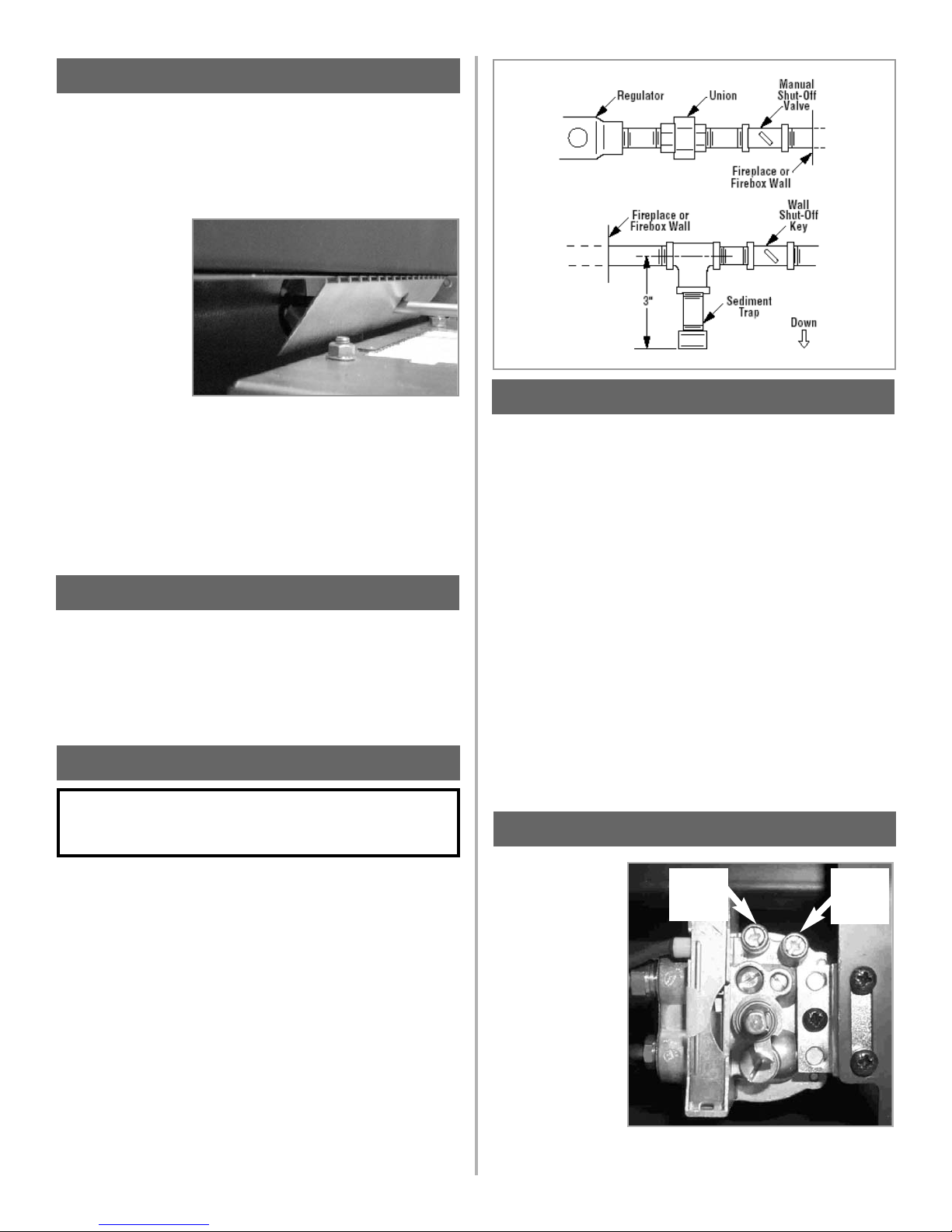
Turn on gas supply and test for gas leaks using a gas leak test solution
(also referred to as bubble leak solution).
NOTE: using a soapy water solution (50% dish soap, 50% water) is an
effective leak test solution, but it is not recommended, because the
soap residue that is left on the pipes/fittings can result in corrosion over
time.
A. Light the appliance (refer to the lighting instructions label in the control compartment or on page 10).
B. Brush all joints and connections with the gas leak test solution to
check for leaks. If bubbles are formed, or gas odor is detected, turn the
gas control knob (off/pilot/on) to the “OFF” position. Either tighten or
refasten the leaking connection, then retest as described above.
C. When the gas lines are tested and leak free, be sure to rinse off the
leak testing solution.
D. Observe the individual tongues of flame on the burner. Make sure all
ports are open and producing flame evenly across the burner. If any
ports are blocked, or partially blocked, clean out the ports.
The pressure should
be checked with the
gas heater burning
and the control set to
high flame.
The pressure
regulator on manual
models is preset and
locked to avoid
tampering. If the
pressure is not as
specified in the
Appliance Data section on page 2,
replace the regulator
with P/N FT/F730031. Replace the test point screws after pressure
measurement ensuring no gas leaks. All instructions must be handed to
the user for safekeeping.
If a concealed gas connection is to be made ensure the gas supply pipe
is in it’s final position and can enter the appliance in the correct position
when the appliance is hung on the wall.
Insert the wall mounting screws into the top wall plugs, taking care to
leave the screws
protruding
approximately 3/8”
from the wall. Now
hang the appliance
onto these screws
through the two
keyhole shaped
holes in the back
panel of the
appliance.
Insert the lower
mounting screws into the lower wall plugs through the corresponding
holes in the lower part of the back panel. Do not tighten fully.
Before tightening the wall mounting screws fully, at this stage it is
recommended to check the horizontal alignment of the appliance with a
spirit level, as small adjustments can still be made if necessary. When
this has been checked, tighten all four fixing screws fully. To access the
upper fixing screws insert a screwdriver through the holes in the
deflector plates above the catalyst as shown in figure 7.
There are no imitation fuel bed components to install. The appliance
features a ribbon burner which is designed to produce a continuous
band of flame over its length. The burner should be visually inspected
to ensure it is free from any foreign matter. If it is necessary to clean or
dust off the burner then the glass door should be removed by removal
of the five retaining screws. Re-fit the glass door after cleaning or
inspection, ensuring a good seal.
A qualified gas appliance installer must connect the gas room heater to
the gas supply.
Consult all local codes. Route gas line using techniques and materials
prescribed by local and/or national codes. Only use pipe of 1/2" or
greater diameter to allow full gas volume to the gas fireplace. Undue
pressure loss will occur if the pipe is too small.
An ANSI approved manual shut-off valve and union must be installed
upstream of the heater within the fireplace cavity when rigid pipe is
used. Ensure that a sediment trap is installed upstream of the heater
(figure 8) within the structure’s piping system to prevent moisture and
contaminants from passing through the pipe to the heater controls and
burner. Failure to do so could prevent the heater from operating reliably.
The heater gas inlet connection is 3/8” NPT at the regulator, located
below the burner, in the center of the heater. When tightening up the
joint to the regulator hold the regulator securely with a wrench to
prevent the regulator from moving.
6
11.0 CONNECTING A GAS LINE
12.0 CHECKING THE GAS CONNECTIONS
IMPORTANT: HOLD HEATER REGULATOR WITH A
WRENCH TO PREVENT MOVEMENT WHEN CONNECTING
TO INLET PIPING.
13.0 GAS PRESSURE CHECK
Burner
(Manifold)
pressure
Regulator
pressure
setting
Figure 9
9.0 MOUNTING THE APPLIANCE - continued
Figure 7
10.0 CHECKING THE BURNER
Figure 8
Page 7
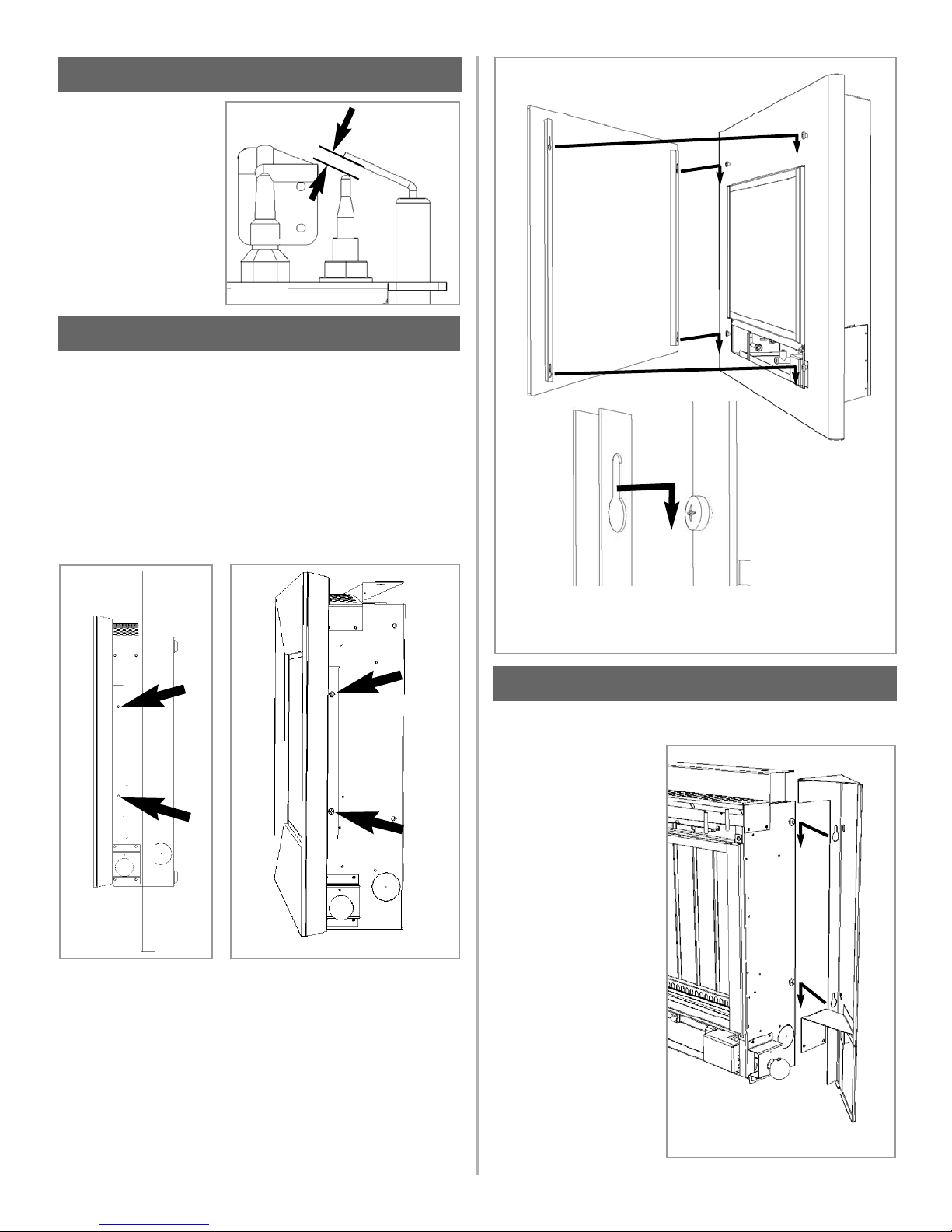
The gap between the
spark electrode and the
pilot should be 1/8” to
3/16” to produce a good
spark. There should be no
need to adjust this. If
under any circumstances
the piezo electric spark
fails, the pilot cannot be lit
manually.
Athos models : The front frame is attached to the firebox using four
self tapping screws (two each side) as shown below in figure 12.
Ensure that the inside edges of the frame are pushed up to the
stainless steel window frame fully.
Reflection models : The front section of the frame assembly should
now be fitted. Remove the extruded frame assembly from the
packaging. Position the frame onto the front of the fire, ensuring that the
inside edges of the frame are pushed up to the stainless steel window
frame fully. Insert four self tapping in the positions on the side of the
firebox as shown below in figure 11.
Scandium and Neon models : The glass facia panel is supported by
four M6 screws which protrude from the front of the outer casing. Insert
the M6 retaining screws and ensure they are unscrewed approximately
1/8” so the keyhole shaped holes may engage, and the facia can be
hooked on. Ensuring that the corresponding keyhole shaped holes
engage the screwheads fully. Refer to figure 13.
7
15.0 FINAL FITTING OF THE FRAME ASSEMBLY
14.0 SPARK GAP
Figure 10
Spark gap
Figure 11
Figure 12
Neon model shown as example
Figure 13
16.0 FITTING THE SIDE PANELS
Athos, Scandium and Neon models only :
Remove the two side panel
assemblies from the
protective packaging and
fit onto the sides of the
firebox as shown. Insert the
M6 retaining screws in the
sides of the firebox and
ensure they are unscrewed
approximately 2mm so the
keyhole shaped holes may
engage, and the sides can
be hooked on.
Note : Front frame/facia not shown
for clarity.
Figure 14
Page 8
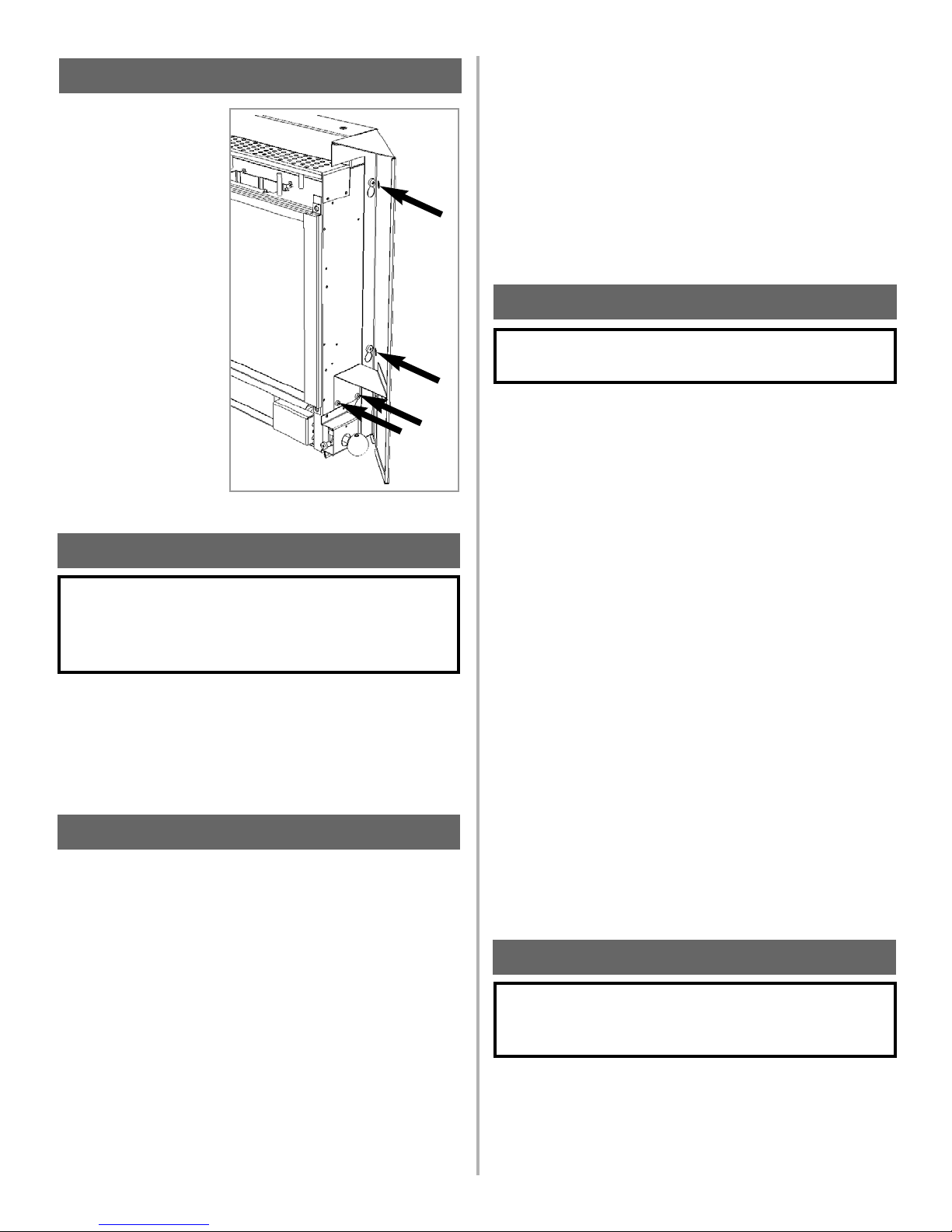
Insert a screwdriver
through the holes in the
right hand side panel to
access the two M6 fixing
screws (designated ‘a’ in
the diagram above) and
tighten fully. Next insert two
no.8 self tapping screws
(designated ‘b’ in the
diagram above) through
the side panel support
bracket, and the
corresponding holes in the
side of the firebox. Tighten
fully.
Repeat for the left hand
side panel, which is
secured by tightening the
M6 ‘a’ screws only.
The right-hand side panel
has a hinged flap
(Scandium and Neon models) to allow access to the control knob.
Advise that cleaning of the fire may be achieved when the fire is cold
using a damp cloth and mild detergent on most surfaces.
Advise that the fire will emit a "newness" smell for a time after initial
commissioning and that extra ventilation may be needed during this
time. Recommend that a guard be used for the protection of the young,
pets, the elderly and the infirm.
Isolate the fire from the gas supply. Ensure that the fire is fully cold
before attempting service. A suggested procedure for servicing is
detailed as follows;
1. Lay out the dustsheet and tools.
2. Remove the front section. This is the reverse procedure to
that detailed in section 15.0.
3. Remove the glass door assembly (5 screws) and clean
carefully.
4. Inspect the burner and the catalysts and clean if necessary
with a soft brush.
5. Disconnect the gas supply.
6. Undo the four screws retaining the burner support brackets to
the base and rear of the firebox.
7. Remove the control knob spindle retaining clip, and withdraw
the control knob assembly.
8. Remove the burner unit, strip off the burner pipes and clean
thoroughly.
9. Clean the in-line restrictor, pilot assembly and the burner
tube. Do not attempt to remove the pilot injector as this can
cause damage.
10. Re-assemble components.
11. Turn on the gas supply and leak test. Check pilot and
burner for good ignition.
12. Refit the glass door assembly, ensuring a good seal.
13. Refit the casing as detailed in section 15.0.
14. Check the purpose provided ventilation is unobstructed.
15. Light the fire and test setting pressures.
16. Check safe operation of the appliance.
For specific servicing instructions, see relevant sections.
First, remove the front section of the frame (as per section 15.0), the
glass panel, and disconnect the gas connection inside appliance. The
gas connections to the gas valve can now be released. Undo the four
screws retaining the burner. Remove the control knob spindle retaining
clip, and withdraw the control knob assembly. The burner may now be
removed.
Remove the pilot and main burner pipes and blow through to dislodge
any debris. Now remove the in line restrictor and blow through to make
sure it is entirely clear.
Unclip the pilot lint gauze and clean with a soft brush. Clean the exterior
of the pilot assembly with a soft brush and blow through the flame ports
on the pilot head. Check the aeration holes are free from lint or dirt. The
pilot assembly can be removed if required by disconnecting the
electrode HT lead, gas pipe and thermocouple lead, unscrewing the
mounting screws and lifting away. The pilot assembly is a nonserviceable item and should not be taken apart. Aeration holes must be
absolutely clear internally for proper operation. NEVER MODIFY OR
BEND THE THERMOCOUPLE TO MAKE THE PILOT STAY ALIGHT.
Modifications are dangerous and can have serious unseen effects on
safety. If the pilot will not stay lit there is a problem with dirt, the gas
supply to it, or the thermocouple needs replacement.
The gas valve is a non-serviceable item. If this needs replacement,
remove the indicator plate then the securing screw holding the valve
bracket in place, remove all pipe unions, and the complete valve.
Replacement must be original manufacturers parts.
Re-assemble in the reverse of removal. Ensure setting pressures are
as stated in Section 3; Appliance Data.
Remove the casing, glass panel and burner unit (as per servicing section), lint arrestor and pilot unit by using a screwdriver to remove the
retaining screws.
Clean the pilot assembly with a soft brush and blow through. Check the
aeration holes are free of any dirt or lint.
8
17.0 BRIEFING THE CUSTOMER
WARNING: DO NOT ADD LOGS OR ORNAMENTS
SUCH AS PINE CONES, VERMICULITE OR ROCK
WOOL. USING THESE ADDED ITEMS CAN CAUSE
SOOTING.
18.0 SERVICING
19.0 SERVICING THE BURNER
WARNING: ANY CHANGE TO THIS HEATER OR ITS
CONTROLS CAN BE DANGEROUS.
16.0 FITTING THE SIDE PANELS - continued
‘a’
‘a’
‘b’
‘b’
20.0 PILOT ASSEMBLY
WARNING: NO ADJUSTMENTS ARE TO BE MADE TO
THE ODS PILOT SYSTEM. TAMPERING WITH THIS
SYSTEM CAN BE EXTREMELY HAZARDOUS.
Figure 15
Page 9
Remove the casing, glass panel and burner unit (as per servicing section), lint arrestor and pilot unit by using a screwdriver to remove the
retaining screws.
Clean the pilot assembly with a soft brush and blow through. Check the
aeration holes are free of any dirt or lint. Clean thoroughly internally,
the connection can be removed from the base of the pilot unit using two
spanners to make cleaning easier. Do not damage or try to dismantle
the pilot injector.
The unit is factory set and the only check necessary is to ensure the
spark gap is correct. See specifications for gas setting.
NEVER MODIFY OR BEND THE THERMOCOUPLE TO MAKE THE
PILOT STAY ALIGHT. If the pilot will not stay lit there is a problem with
dirt, the gas supply, or the thermocouple needs replacement.
Modifications are dangerous and can have a serious unseen effect on
safety and therefore MUST not be done. Replacements must be original manufacturers parts. Re-assemble in the reverse of removal.
Ensure setting pressures are as stated in Section 3; Appliance Data.
It is recommended that the catalysts are inspected for signs of damage
and dirt during routine servicing procedures. The expected life of the
catalysts is in excess of 11,000 hours (10 years of normal use). After
this time the catalyst should be replaced.
If there are any deposits of dirt or soot on the catalysts they should be
cleaned with a soft brush and a vacuum cleaner. If removed for cleaning
ensure the seals are in good condition before replacing the catalyst.
New seals will usually be required.
The performance of the catalyst may be checked using a combustion
gas analyzer as follows.
Important: The temperature of the gases emitted by the catalytic
converters is in excess of 700
o
F. Measuring gas of this temperature
may damage some types of gas analyzers. If in doubt consult the
equipment manufacturer.
Ignite the fire as per the operating instructions, and run at maximum
setting for 15 minutes. Position gas sample probe directly over a catalyst via the outlet grille, on top of the appliance. Record the carbon dioxide (CO2) concentration and then the carbon monoxide (CO)
concentration as displayed by the analyzer - also noting the units in
which the values are expressed. Most analyzers display carbon dioxide
(CO2) concentrations in percentage (%) terms and carbon monoxide
concentration in parts per million (ppm) terms.
In order to calculate the combustion ratio for the appliance (CO/CO2) it
is first necessary to express both gas concentrations in terms of percentage. To convert from parts per million (ppm) to a percentage (%)
divide the ppm figure by 10,000. Examples : 35ppm = 0.0035%, 15ppm
= 0.0015%, 5ppm = 0.0005%.
Now divide the concentration of carbon monoxide (CO) expressed in
percent by the concentration of carbon dioxide (CO2) to obtain the
appliance combustion ratio.
The combustion ratio of the gasses emitted by the catalytic convertor
should not exceed 0.0015.
If replacing, firstly, remove the decorative fire frame as described in
section 15.0. The catalysts are located on the top of the internal firebox
and can be removed be unscrewing the retaining nuts securing the
clamping plate. Remove the catalysts and seals and discard.
Refit a new catalysts and seals in reverse order, ensure the catalysts
and door have good seals.
Appliances that are several years old or have been extensively dismantled should be checked for soundness. It is important that all the products of combustion pass through the catalytic convertors at the top of
the firebox before leaving the appliance.
The firebox is heated by lighting for a few minutes to provide a flow
through the firebox. The burner is then shut off and a smoke pellet or
match introduced at the base of the fire underneath the burner tray.
Large quantities of smoke will emerge from the top of the appliance, but
none should emerge from the joints or gasket faces, especially around
the door. It is important to note that the appliance can never be expected to be 100% smoke tight and small quantities of smoke may be seen
in corners of joints and gasket faces etc without affecting safety when
the fire is in operation.
GLASS PANEL -This can be cleaned with a suitable glass cleaner, or
proprietary ceramic hob cleaner. Test on a small area first.
PAINTED AREAS - These can be cleaned using a dry cloth.
STAINLESS STEEL AREAS - These can either be cleaned using a
proprietary stainless steel metal cleaner or baby oil. Test on a small hidden part of the stainless steel before cleaning. Always clean in the
direction of the grain.
9
21.0 CATALYSTS
CO (%)
CO2 (%) = ratio
22.0 TESTING FOR FIREBOX LEAKAGE
23.0 CLEANING
WARNING: TURN OFF THE UNVENTED GAS ROOM
HEATER AND ALLOW TO COOL BEFORE CLEANING.
20.0 PILOT ASSEMBLY - continued
Page 10
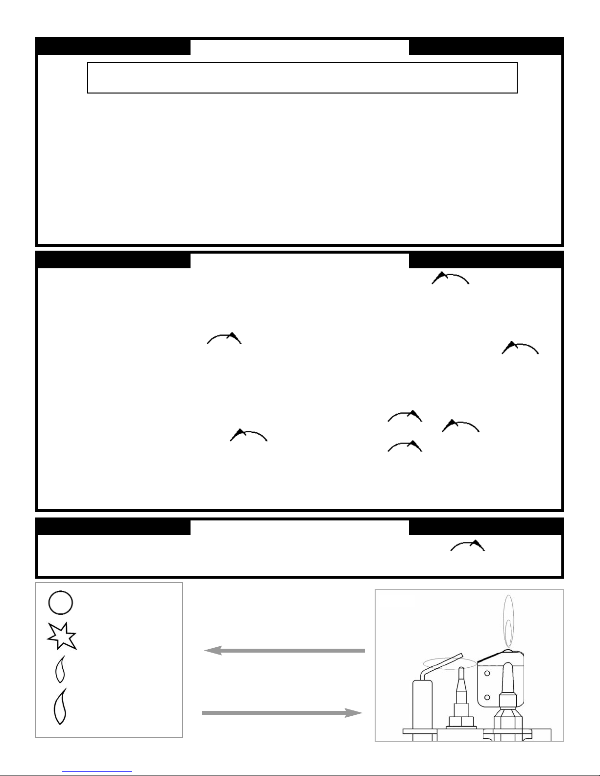
FOR YOUR SAFETY READ BEFORE LIGHTING
WARNING: IF YOU DO NOT FOLLOW THESE INSTRUCTIONS EXACTLY, A FIRE OR EXPLOSION MAY
RESULT CAUSING PROPERTY DAMAGE, PERSONAL INJURY OR LOSS OF LIFE.
A. This heater has a pilot which must be lit by hand. When
lighting the pilot, follow these instructions exactly.
B. BEFORE OPERATING smell all around the heater area for gas.
Be sure to smell next to the floor because some gas is
heavier than air and will settle on the floor.
WHAT TO DO IF YOU SMELL GAS
• Do not try to light any appliance.
• Do not touch any electric switch; do not use any phone in
your building.
• Immediately call your gas supplier from a neighbor’s phone.
Follow the gas supplier’s instructions.
• If you cannot reach your gas supplier, call the fire department.
C. Use only your hand to push in or turn the gas control knob.
Never use tools. If the knob will not push in or turn by hand, do
not try to repair it, call a qualified service technician. Forced or
attempted repair may result in a fire or explosion.
D. Do not use this heater if any part has been under water.
Immediately call a qualified service technician to inspect the
appliance and to replace any part of the control system and
any gas control which has been under water.
24.0 LIGHTING INSTRUCTIONS
1. Stop! Read the safety information above.
2. Make sure manual shut-off valve is fully open.
3. Open the control access panel (if applicable).
4. Depress control knob in and turn clockwise to the
“OFF” position ( Figure 16).
5. Wait 5 minutes to clear out any gas. Then smell for gas, including near
the floor. If you smell gas, STOP! Follow the safety instructions in “What
to do if you smell gas” under section ‘B’ above. If you do not smell gas,
go to next step.
6. The pilot is located on the left side behind the burner (Figure 17).
7. Depress control knob in and turn counterclockwise
to the “SPARK” position ( Figure 16 ) and hold there for a few seconds.
Note: If you are running the heater for the first time or after an extended
period of non use it will be necessary to press the control knob all the
way in for 30 seconds to allow air to bleed out of the gas piping.
8. Continue turning counterclockwise through the spark
click to the PILOT light position, ensuring the pilot has lit. If not, turn the
knob fully clockwise, and repeat.
9. Hold the control knob in for a further 10 seconds to prevent the flame
failure detector from shutting off the gas while the probe is warming up.
10. Release the control knob while turning counterclockwise
to the preferred setting. Close the control access panel.
• If the knob does not pop out when released, stop and immediately call
your service technician or gas supplier.
• If the pilot will not stay lit after several tries, depress and turn the gas
control knob clockwise to “OFF”and wait 30 seconds.
Depress and turn knob counterclockwise to “SPARK” and
ignite the heater again. If your pilot does not relight depress and turn
control knob clockwise to “OFF” and call your service
technician or gas supplier.
11. Wait 30 seconds before readjusting the heater when the control knob
has been turned down to a lower setting.
25.0 TO TURN OFF GAS TO APPLIANCE
2. Depress and turn control knob clockwise to the “OFF”
position (Figure 16). Close the control access panel.
1. Open the control access panel.
Figure 16 : The control knob is located on the
lower right hand side of the outer case. It is of
a spherical design and is marked as shown in
the diagram to the right;
Figure 17 :Pilot unit. This is located behind
the burner, on the left-hand side of the
appliance.
Figure 17
10
‘OFF’ position
‘SPARK’ position
‘LOW’ position
‘HIGH’ position
Figure 16
Page 11

Fire sparks but pilot does not light No gas to fire, check isolators are open.
Pipe work blockage, clean out.
Air not fully purged, re purge supply or wait longer.
Spark grounding to metal work, reset gap correctly.
Blocked pilot, clean out internally.
Pilot lights but then goes out Severe restriction in gas supply: clear obstruction.
Faulty thermocouple, replace pilot unit.
Blocked pilot, clean out.
Blocked lint gauze, clean.
Hold control knob in for longer.
Check control knob does not foul data plate.
If the pilot will not stay lit there is a problem with dirt, the gas supply, or the thermocouple needs
replacement. Modifications are dangerous and can have a serious unseen effect on safety.
NEVER MODIFY OR BEND THE THERMOCOUPLE TO MAKE THE PILOT STAY ALIGHT.
Fire does not spark at pilot HT lead detached, refit.
Check the spark gap (see section 14.0).
Faulty piezo unit, replace.
Debris shorting out electrode, clean.
Spark shorting to metalwork under tray, realign HT lead.
Fire runs for a time and then cuts off Loose or faulty thermocouple, rectify.
Blocked pilot, clean out.
Dirt or lint in pilot aeration hole or on the lint gauze, clean thoroughly.
If the pilot will not stay lit there is a problem with dirt, the gas supply, or the thermocouple needs
replacement. Modifications are dangerous and can have a serious unseen effect on safety.
NEVER MODIFY OR BEND THE THERMOCOUPLE TO MAKE THE PILOT STAY ALIGHT.
Pilot flame shrinks when fire is on high Poor gas flow to fire, check pressure with fire on high.
If pressure is low, remove any restriction in pipework or valve.
Check all isolators are adequately sized and fully open.
Check meter pressure is adequate.
If the pilot will not stay lit there is a problem with dirt, the gas supply, or the thermocouple needs
replacement. Modifications are dangerous and can have a serious unseen effect on safety.
NEVER MODIFY OR BEND THE THERMOCOUPLE TO MAKE THE PILOT STAY ALIGHT.
Fire smells when first lit or in use Newness smell from brand new appliance.
Leakage occurring. Carry out leakage test and rectify any problems.
Combustible materials used in incorrect positions.
11
26.0 TROUBLESHOOTING GUIDE
27.0 REPLACEMENT PARTS
Description Part number
Glass door assembly FB/F960004
Gas Valve FT003155/0
Catalyst FB/F780079
Pilot unit FT/F730023
Burner unit TRAY 052
Seal kit for catalyst IN/F940136
Inlet pressure regulator FT/F730031
Decorative front frame Please enquire
Decorative rear frame Please enquire
When ordering spare parts, always give the following information;
1. The model number of the heater.
2. The serial number of the heater.
3. The part number.
4. The description of the part.
5. The quantity required.
6. The installation date of the heater.
If you encounter any problems, require spare parts, or have any
questions concerning the installation of the heater please contact;
Focal Point (North America)
5555 Pleasantdale Road
Doraville, Georgia 30340
Toll free :1 800 704 6093
Fax: 770 368 8261
E-mail : [email protected]
Manufactured by :
Focal Point Fires plc.
Christchurch, Dorset
United Kingdom BH23 2BT
Page 12
12
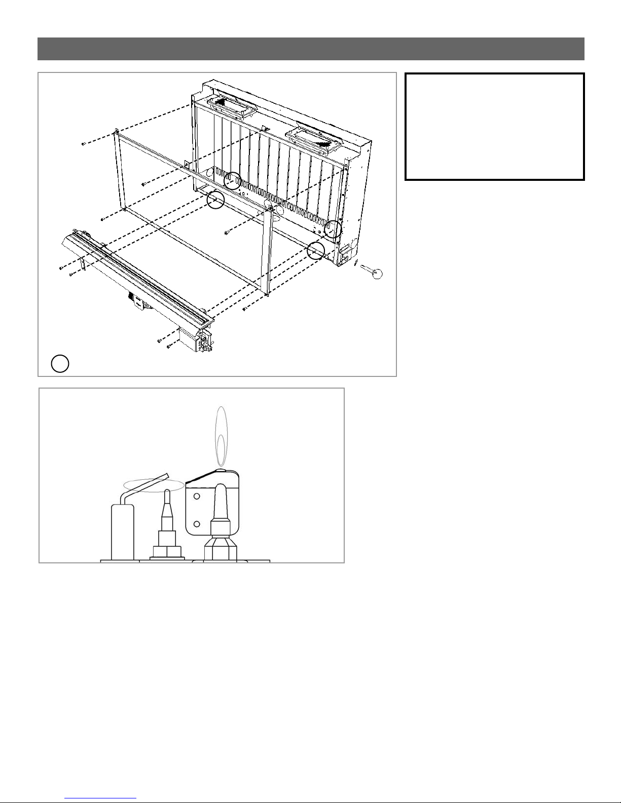
Figure 18
Figure 19
Figure 18 : Removal and refitting of glass
door assembly and burner assembly.
Figure 19 : Visual check
for correct pilot flame.
denotes 4 off burner fixing points
WARNING: FAILURE TO POSITION
THE PARTS IN ACCORDANCE WITH
THESE DIAGRAMS OR FAILURE TO
USE ONLY PARTS SPECIFICALLY
APPROVED WITH THIS HEATER
MAY RESULT IN PROPERTY
DAMAGE OR PERSONAL INJURY.
As our policy is one of continuous improvement and development , we hope therefore you will understand we must retain the right to amend details and/or specifications without prior notice.
DO005566/0
28.0 POSITIONING OF FIELD REMOVABLE PARTS
Page 13
13
UTILIZAR ÚNICAMENTE CON CALENTADORES DE TIPO
DECORATIVO SIN SALIDA DE HUMOS.
No guarde ni utilice gasolina u otros vapores o líquidos
inflamables cerca de este o de otros aparatos.
QUÉ HACER SI USTED NOTA OLOR A GAS
• NO ENCIENDA ningún aparato eléctrico.
• NO TOQUE ningún interruptor eléctrico.
• NO UTILICE ningún teléfono de su edificio.
• Llame inmediatamente a su compañía de gas desde el
teléfono de un vecino.
• Siga las instrucciones de su compañía de gas.
• Si no puede contactar con su compañía de gas, llame a
los bomberos.
La instalación y el mantenimiento deben ser realizados por
un instalador o empresa de mantenimiento autorizado, o
por la compañía de gas.
ADVERTENCIA: SI NO SE SIGUEN EXACTAMENTE LAS
INDICACIONES DE ESTE MANUAL, PUEDE
PRODUCIRSE UN INCENDIO O UNA EXPLOSIÓN, CON
RESULTADO DE DAÑOS MATERIALES, LESIONES
PERSONALES O PÉRDIDA DE LA VIDA.
CALENTADOR DE PARED SIN SALIDA DE HUMOS
INSTRUCCIONES DE INSTALACIÓN
El instalador y el cliente deben
guardar el manual del aparato
junto con el aparato instalado
ADVERTENCIA: LA INSTALACIÓN, AJUSTE, MODIFICACIÓN,
REVISIÓN O MANTENIMIENTO INADECUADOS PUEDEN CAUSAR
LESIONES O DAÑOS MATERIALES. CONSULTE ESTE MANUAL.
SI NECESITA AYUDA O INFORMACIÓN ADICIONAL CONSULTE A
UN INSTALADOR CALIFICADO, A UNA EMPRESA DE
MANTENIMIENTO O A LA COMPAÑÍA DE GAS.
ADVERTENCIA: NO HAGA UN FUEGO DE LEÑA. NO
QUEME MADERA U OTROS MATERIALES EN ESTE
APARATO.
Éste es un calentador de gas sin salida de humos. Consume
aire (oxígeno) de la habitación en la que está instalado. Es
necesario proporcionar un suministro adecuado de aire de
combustión y ventilación. Consulte la sección Aire de
combustión y ventilación, página 15.
Este aparato puede ser instalado en una casa prefabricada
(móvil) con ubicación permanente una vez adquirida,
siempre que no lo prohíba la normativa local.
El aparato debe utilizarse únicamente con el tipo de gas
indicado en la placa de características. Este aparato no es
convertible para el uso con otros tipos de gases.
Versión C - 15/06
INSTALADOR:
DEJE ESTE MANUAL JUNTO AL APARATO.
CONSUMIDOR:
GUARDE ESTE MANUAL PARA SU CONSULTA EN EL FUTURO.
Debido a las altas temperaturas generadas, el aparato debe
ubicarse en un lugar con poco tránsito, alejado de muebles y
cortinas. No coloque ropa u otros materiales sobre o cerca de
este aparato.
MODELO : F500079
REFLECTION
MODELO : F500083
NEON
MODELO : F500082
ATHOS
MODELO : F500081
SCANDIUM
317-S-03-5 (Reflection)
317-S-07-5 (Neon)
317-S-06-5 (Athos)
317-S-05-5 (Scandium)
Report No’s :
Page 14

Este aparato es un calentador de gas de alta eficacia, sin salida de humos,
con efecto de llama. Proporciona calor por radiación y por convección de
manera eficiente y segura, utilizando las últimas tecnologías de combustión
con conversión catalítica. El aparato no necesita ningún sistema de
evacuación de humos, puesto que el convertidor catalítico limpia los residuos,
proporcionando un completo sistema de combustión, que es intrínsecamente
seguro.
Estos calentadores incorporan un piloto de diseño especial que utiliza un
sensor de agotamiento de oxígeno (ODS) que detecta la cantidad de oxígeno
que queda en la habitación y apaga el calentador antes de que el nivel de
oxígeno caiga por debajo del 18%. El piloto sólo puede ser encendido de
nuevo cuando haya suficiente aire fresco. Consulte la sección Aire de
combustión y ventilación.
El diseño del aparato permite su instalación en diferentes situaciones, según
se indica en los Requisitos de instalación.
Este aparato viene ajustado de fábrica para el tipo de gas y la presión
indicados en la placa de características del aparato.
Cuando se enciende un aparato nuevo por primera vez, el olor “a nuevo”
desaparecerá después de las primeras horas de uso. Durante este periodo es
posible que se emita cierta cantidad de humo por la rejilla de salida; esto es
normal y no debe ser causa de preocupación. Por ello, la habitación debe
ventilarse bien, dejando abiertas todas las puertas y ventanas durante este
periodo.
Lea todas estas instrucciones antes de comenzar la instalación.
Todas las instrucciones deben ser entregadas al usuario para su
conservación.
CANTIDAD DESCRIPCIÓN
1 Conjunto de cámara de combustión y quemador
1 Instrucciones de instalación y operación
1 Conjunto de panel decorativo de vidrio (Modelos Scandium y Neon)
1 Conjunto de marco de aluminio (Modelos Athos y Reflection)
1 Conjunto de marco trasero (Modelos Neon y Reflection)
1 Paquete de tornillos y tacos de pared
1 Pasamuros de goma
1 Plantilla de instalación
ESTADO DE MASSACHUSETTS: LA INSTALACIÓN DEBE SER REALIZADA
POR UN PLOMERO O INSTALADOR DE GAS AUTORIZADO EN EL ESTADO
DE MASSACHUSETTS.
Envenenamiento por monóxido de carbono: Las primeras señales del
envenenamiento por monóxido de carbono son parecidas a las de la gripe,
e incluyen dolor de cabeza, mareo y/o náuseas. Si usted nota estos
síntomas, busque aire fresco inmediatamente. Apague el suministro de gas
al aparato y haga que lo revise un profesional calificado, porque es posible
14
ADVERTENCIA: EL INCUMPLIMIENTO DE LAS INSTRUCCIONES
DE INSTALACIÓN Y SEGURIDAD PROPORCIONADAS EN ESTE
DOCUMENTO DARÁ LUGAR A UN APARATO MAL INSTALADO DE
FUNCIONAMIENTO INCORRECTO, ANULANDO SU GARANTÍA.
CUALQUIER MODIFICACIÓN DE ESTE APARATO Y/O SUS
CONTROLES DE OPERACIÓN ES PELIGROSO. LA INSTALACIÓN
O EL USO INCORRECTOS DE ESTE APARATO PUEDEN CAUSAR
GRAVES LESIONES O LA MUERTE POR INCENDIO,
QUEMADURAS, EXPLOSIÓN O ENVENENAMIENTO POR
MONÓXIDO DE CARBONO.
1.0 INFORMACIÓN GENERAL
2.0 INVENTARIO
4.0 INFORMACIÓN DE SEGURIDAD IMPORTANTE
TABLE OF CONTENTS
3.0 APPLIANCE DATA
Tipo de gas Gas natural
Presión de entrada de gas Máxima 10,5” cda
Mínima 6” cda
Ajuste de presión del regulador 5” cda
Consumo máximo de energía 8.870 BTU/hora
Consumo mínimo de energía 5.110 BTU/hora
Consumo de energía del piloto 560 BTU/hora
Presión del quemador (colector) Alta 3,6” cda (+/-0,3” cda) Caliente
3,5” cda (+/-0,3” cda) Frío
Baja 1,2” cda (+/-0,3” cda) Caliente
1,1” cda (+/-0,3” cda) Frío
Restricción de caudal del quemador principal Estéreo 1,45 mm (1/4” BSP)
Piloto con sensor de oxígeno SIT/Bray 9082
Conexión de entrada de gas 3/8” NPT en el regulador
Encendido Piezoeléctrico, por chispa
Espacio entre electrodos 3/16”
Consulte en la placa de características fijada al aparato las especificaciones
actuales. Este aparato debe utilizarse únicamente con el tipo de gas y a la
presión indicados en la placa de características del aparato.
IMPORTANTE: LEA Y COMPRENDA COMPLETAMENTE ESTAS
INSTRUCCIONES ANTES DE INSTALAR O PONER EN
FUNCIONAMIENTO SU CALENTADOR SIN SALIDA DE HUMOS.
ADVERTENCIA: EL NO MANTENER LIMPIA(S) LA(S) ABERTURA(S) PRINCIPAL(ES) DE VENTILACIÓN DEL/DE LOS QUEMADOR(ES) PUEDE PRODUCIR HOLLÍN Y DAÑOS MATERIALES.
Sección Contenido Página Nº
1.0 Información general 14
2.0 Inventario 14
3.0 Especificaciones del aparato 14
4.0 Información de seguridad importante 14
5.0 Normativa 15
6.0 Aire de combustión y ventilación 15
7.0 Requisitos del lugar de ubicación 16
8.0 Preparación del aparato 17
9.0 Montaje del aparato 17
10.0 Comprobación del quemador 18
11.0 Conexión de un conducto de gas 18
12.0 Comprobación de las conexiones de gas 18
13.0 Comprobación de la presión del gas 18
14.0 Espacio entre electrodos 19
15.0 Instalación final del conjunto del marco 19
16.0 Colocación de los paneles laterales 19
17.0 Información al cliente 20
18.0 Mantenimiento 20
19.0 Mantenimiento del quemado 20
20.0 Montaje del piloto 20
21.0 Catalizadores 21
22.0 Comprobación de fugas de la cámara de combustión 21
23.0 Limpieza 21
24.0 Instrucciones de encendido 22
25.0 Cómo cerrar el paso de gas al aparato 22
26.0 Guía de solución de problemas 23
27.0 Lista de piezas de repuesto 23
28.0 Ubicación de piezas ensambladas in situ 24
Page 15

• Es necesario advertir a niños y adultos del peligro de la alta temperatura de
la superficie, y éstos deben mantenerse alejados para evitar quemaduras o
que se les prenda fuego la ropa.
• Es necesario supervisar cuidadosamente a los niños pequeños cuando
estén en la misma habitación que el calentador.
• No coloque ropa u otros materiales inflamables sobre o cerca del
calentador.
• Cualquier rejilla o protector de seguridad que se retire para realizar tareas
de mantenimiento en el calentador debe ser repuesto antes de ponerlo en
funcionamiento.
• La instalación y las reparaciones deben ser realizadas por un profesional
de mantenimiento calificado. El calentador debe ser inspeccionado antes del
uso, y al menos una vez por año, por un profesional de mantenimiento
calificado. Puede ser necesario limpiar más a menudo debido a pelusas
provenientes de moquetas y alfombras, ropa de cama, etc..
Es importante mantener limpios los compartimentos de control, los
quemadores y los pasos de aire del calentador.
• Deje que se enfríe el calentador antes de realizar tareas de mantenimiento.
Cierre siempre el paso de gas al calentador al realizar trabajos de
mantenimiento.
• La instalación debe realizarse de acuerdo con la normativa local, o en su
ausencia, con el National Fuel Gas Code (Código Nacional del Gas), ANSI
Z223.1.
• El calentador y su llave de paso individual deben ser desconectados del
sistema de tuberías de suministro de gas durante la realización de pruebas
del sistema de tuberías de suministro de gas a una presión superior a 1/2
psig.
• El calentador debe ser aislado del sistema de tuberías de suministro de gas
cerrando su llave de paso manual individual durante cualquier prueba de
presión del sistema de tuberías de suministro de gas a una presión de
prueba igual a o menor de 1/2 psig.
• Mantenga la zona del calentador despejada y libre de materiales
combustibles, gasolina y otros vapores y líquidos inflamables.
• No utilice este calentador si cualquier parte del mismo ha estado
sumergida en agua. Llame inmediatamente a un técnico de mantenimiento
calificado para que inspeccione el calentador y cambie cualquier pieza del
sistema de control y cualquier control de gas que haya estado sumergido en
agua.
• Las cifras de consumo se indican en BTU por hora, y son para altitudes de
hasta 4.800 pies. No instale este calentador a altitudes de más de 4.800 pies
si el suministro de gas no ha sido ajustado para dicha elevación. Consulte a
su compañía de gas local. (Para el funcionamiento a altitudes de más de
4.800 pies, los valores nominales del equipo habrán de reducirse en un 4 por
ciento por cada 1.000 pies por encima del nivel de mar, antes de seleccionar
equipos del tamaño adecuado.)
• Asegúrese de que el calentador está limpio durante el funcionamiento. Una
acumulación excesiva de polvo en el quemador aumentará la cantidad de
monóxido de carbono formada, y podría ser causa de envenenamiento por
monóxido de carbono y/o la muerte.
• Este aparato está diseñado como calefacción suplementaria
Observe la normativa local o en su ausencia la última edición de The National Fuel
Gas Code ANSI Z223.1 o NFPA54, que pueden obtenerse en The American
National Standards Institute, Inc. (1430 Broadway, New York, NY, 10018) o
National Fire Protection Association, Inc. (Batterymarch Park, Quincy, MA, 02269).
El vendedor de un calentador suplementario de gas natural o propano sin salida
de humos debe proporcionar a cada comprador una copia de 527 CMR 30 en el
momento de la venta de la unidad.
Este Calentador de Gas sin salida de Humos de Focal Point es certificado por
OMNI-Test Laboratories, Inc con arreglo a la norma ANSI Z21.11.2-2004b.
Este calentador no debe instalarse en un espacio confinado o en una construcción
inusualmente estanca a menos que se prevea un suministro suficiente de aire de
combustión y ventilación.
El National Fuel Gas Code, ANSI Z223,1/NFPA 54 define un espacio confinado
como un espacio con un volumen de menos de 50 pies
3
por 1.000 BTU/h (4,8 m
3
por kW) del consumo nominal acumulado de todos los aparatos instalados en
dicho espacio, y un espacio confinado con un volumen de no menos de 50 pies
3
por 1.000 BTU/h (4,8 m3por kW) del consumo nominal acumulado de todos los
aparatos instalados en dicho espacio.
Las habitaciones que se comunican directamente con el espacio en el que están
instalados los aparatos, a través de huecos no provistos de puertas, se consideran
como parte del espacio no confinado.
Una construcción inusualmente estanca se define como una construcción en la
que:
a. la pared y los techos expuestos a la atmósfera exterior tienen un retardador
continuo de vapor de agua con valor de una unidad de permeancia o menos, con
aberturas selladas o con juntas, y
b. se han añadido burletes impermeabilizantes en las ventanas y puertas
practicables, y
c. se han aplicado masillas o selladores a zonas tales como juntas alrededor de
marcos de ventanas y puertas, entre cimentaciones y suelos, entre las juntas
pared-techo, entre paneles de pared, en orificios para conductos sanitarios,
eléctricos y de gas, y en otras aberturas.
Utilice las siguientes ecuaciones para determinar si usted tiene un espacio
confinado o no confinado.
15
5.0 NORMATIVA
6.0 AIRE DE COMBUSTIÓN Y VENTILACIÓN4.0 INFORMACIÓN DE SEGURIDAD IMPORTANTE (cont.)
Determine el volumen del espacio — pies
3
Longitud x Ancho x Alto = _____ pies
3
(Incluir habitaciones colindantes con pasillos sin puertas o rejillas de
ventilación entre habitaciones.)
Ejemplo: 24' (Largo) x 16' (Ancho) x 8' (Alto) = 3072 pies
3
Divida el volumen del espacio entre 50 pies 3para determinar el máximo
de BTU/h que el espacio puede soportar.
______ (volumen del espacio – pies
3
)/ 50 pies 3=
(Máximo de BTU/h que el espacio puede soportar)
Ejemplo: 3072 pies 3 / 50 pies 3 = 61,44
o 61.440 BTU/h que el espacio puede soportar.
Sume las BTU/h de todos los aparatos quemadores de combustible del
espacio.
Calentador sin salida de humos _______ BTU/h
Aparato de gas Nº 1* _______ BTU/h
Aparato de gas Nº 2 + _______ BTU/h
Aparato de gas Nº 3 + _______ BTU/h
Total = _______ BTU/h
Ejemplo:
Calentador sin salida de humos Nº 1 9.000 BTU/h
Calentador sin salida de humos Nº 2 32.000 BTU/h
Aparato de gas Nº 1 35.000 BTU/h
(calentador de agua)
Total = 67.000 BTU/h
* No incluya aparatos de gas con salida de humos directa. La salida de
humos directa tiene combustión sellada y aspira el aire de combustión
desde fuera.
1.
2.
3.
Page 16
El espacio del ejemplo anterior es un espacio confinado porque las BTU/h reales
consumidas son más del máximo de BTU/h que el espacio puede soportar.
Usted debe proporcionar aire fresco adicional.
Sus opciones son:
a. Vuelva a calcular las ecuaciones sumando el espacio de una o más
habitaciones colindantes. Si con el volumen adicional se obtiene un espacio no
confinado, elimine una puerta o añada rejillas de ventilación entre las
habitaciones. Consulte el National Fuel Gas Code, ANSI Z223,1, Sección 5.3.
b.
Proporcione ventilación directa de la habitación con el exterior. Consulte el
National Fuel Gas Code, ANSI Z223,1, Sección 5.3.
c. Instale un calentador de menos BTU/h, para convertir el área en un espacio no
confinado.
Si el consumo real de BTU/h es menor que el máximo de BTU/h que puede
soportar el espacio, entonces el espacio es un espacio no confinado. Usted no
necesita ventilación adicional alguna para un espacio no confinado.
Este aparato está diseñado para ser colgado en una pared. No empotre
ninguna parte del aparato en la pared.
Este aparato puede instalarse en cualquier habitación de la casa, salvo en
cuartos de baño y dormitorios o en zonas en las que es probable que se
generen grandes cantidades de vapor.
Es habitual instalarlo en una sala de estar; no obstante, se permite la instalación
en otras habitaciones tales como cocinas, comedores y pasillos, siempre que
esté disponible un suministro de gas natural, y que la habitación cumpla
estrictamente los requisitos de tamaño y ventilación (ver Sección 6).
El aparato está diseñado para ser versátil, y como tal, funcionará correctamente
en presencia de las corrientes de aire suaves que normalmente se producen
dentro de una casa. No obstante, no se recomienda que se instale el aparato en
zonas en las que probablemente quede expuesto a corrientes fuertes continuas
generadas por puertas o ventanas al exterior, huecos de ventilación, etc.
Se recomienda no instalar el aparato a menos de 20” de cualquier hueco de
ventilación de aire.
Espacio libre hasta superficies no combustibles
Las superficies no combustibles se definen como ladrillo, metal, mármol, hormigón
etc., así como diversos materiales artificiales que son insensibles a las llamas. En
caso de duda, solicite más información al fabricante del material antes de proceder
con la instalación.
Debe dejarse un espacio libre de 4” en los lados del aparato. Debe dejarse un
espacio libre de 20” en la parte frontal del aparato.
La parte trasera del aparato puede instalarse directamente sobre una pared
incombustible, siempre que la zona detrás del aparato sea plana y no obstruya los
diversos orificios de ventilación del panel trasero del aparato.
El aparato puede instalarse con o sin un hogar incombustible. Si se instala un
hogar, puede ser del tamaño y diseño que se desee.
Puede colocarse por encima del aparato un estante incombustible de cualquier
profundidad, siempre que esté a una distancia de no menos de 16” desde la parte
superior del panel de vidrio del aparato y que la pared que está por encima del
aparato sea incombustible.
Espacio libre hasta materiales combustibles
Los materiales combustibles se definen como madera, telas u otros materiales
susceptibles de arder al estar expuestos a una llama. En general, cualquier
material susceptible de decolorarse, derretirse o deformarse al estar expuesto a
un calor moderado debe considerarse como material o superficie combustible.
Debe dejarse un espacio libre de 4” en los laterales del aparato, pero no se
permiten cortinas u otras telas en un espacio de 20” desde los laterales del
aparato. No se permiten materiales de este tipo directamente encima del aparato,
cualquiera que sea la distancia.
La distancia mínima al techo por encima del aparato es de 32”, medida desde el
borde superior del panel de vidrio del aparato.
No deben colocarse materiales combustibles directamente delante del aparato en
una distancia de 40”.
No deben colocarse en ningún caso equipos eléctricos, por ejemplo, televisores
de pantalla de plasma, en la pared por encima del aparato. El aparato está
diseñado para ser montado solo en la pared, no acompañado de ningún tipo de
embellecedor combustible. No deben colocarse estantes combustibles en la pared
por encima del aparato. Es necesario comprobar que cualquier espejo, marco de
cuadro, etc., que se vaya a colocar en la pared por encima del aparato pueda
soportar una exposición prolongada a calor y humedad moderados antes de
proceder a su instalación.
La parte trasera del aparato puede instalarse directamente sobre una pared
combustible, siempre que ésta sea relativamente plana y no obstruya los diversos
orificios de ventilación del panel trasero del aparato. La pared debe ser
estructuralmente robusta, y debe estar construida de un material capaz de
soportar el calor moderado. Algunos ejemplos de materiales adecuados son
enlucidos de yeso, papel pintado convencional y paredes revestidas de cartónyeso. Deben evitarse materiales como papeles pintados aterciopelados, papel
vinílico y papel en relieve, que son sensibles incluso a niveles bajos de calor;
pueden resultar chamuscados y/o decolorados con el tiempo.
Si el aparato va a montarse en una pared revestida de cartón-yeso o en una pared
de armazón de madera, debe confirmarse la integridad de la pared y su capacidad
para soportar el peso del aparato. Es importante en estas circunstancias no dañar
cualquier barrera de control de vapor, y no dañar ningún componente estructural
del armazón de la casa.
El aparato puede colocarse lo más próximo que permita el diseño del marco del
calentador a un piso macizo (piedra, laminado de madera, etc.), pero no está
permitido instalar el aparato a menos de 4” de moqueta, alfombras o telas de
ningún tipo. Esta dimensión se mide verticalmente desde el borde inferior del
marco del aparato.
16
6.0 AIRE DE COMBUSTIÓN Y VENTILACIÓN (cont.)
ADVERTENCIA: SI LA ZONA EN LAQUE EL CALENTADOR PUEDE
SER UTILIZADO ES MENOR QUE LA DEFINIDA COMO ESPACIO
NO CONFINADO, O SI EL EDIFICIO ES DE UNA CONSTRUCCIÓN
INUSUALMENTE ESTANCA, PROPORCIONE UN SUMINISTRO
ADECUADO DE AIRE DE COMBUSTIÓN Y VENTILACIÓN POR
UNO DE LOS MÉTODOS DESCRITOS EN EL NATIONAL FUEL GAS
CODE, ANSI Z223,1/NFPA 54, SECCIÓN 5.3, O EN LA NORMATIVA
LOCAL APLICABLE.
7.0 REQUISITOS DEL LUGAR DE UBICACIÓN
4.
Compare el máximo de BTU/h que el espacio puede soportar con la
cantidad real de BTU/h consumidas.
_______ BTU/h (máx. que puede soportar el espacio)
_______ BTU/h (cantidad real de BTU/h consumidas)
Ejemplo:
61.440 BTU/h (máx. que puede soportar el espacio)
67.000 BTU/h (cantidad real de BTU/h consumidas)
ADVERTENCIA: NO AÑADA UN SOPLADOR, UN
INTERCAMBIADOR DE CALOR U OTRO ACCESORIO NO
HOMOLOGADO PARA EL USO CON ESTE CALENTADOR.
Page 17
Conexión de gas:
La
conexión de entrada de
gas del calentador es de
3/8” NPT en el regulador,
ubicado debajo del
quemador, en el centro
del calentador.
Modelos Reflection:
Hay seis posibles puntos
de entrada por los que
puede pasar la tubería de
suministro de gas a la
cámara de combustión.
Estos puntos de entrada
son orificios obturados
(ilustrados en la Figura 1).
Modelos Neon, Athos
y Scandium:
Hay cuatro
posibles puntos de entrada
por los que puede pasar la
tubería de suministro de
gas a la cámara de
combustión. Estos puntos
de entrada son orificios
obturados (ilustrados en la
Figura 2).
Pueden realizarse
conexiones de gas no
ocultas usando los
puntos de entrada
situados en la base de la
cámara de combustión.
Puede realizarse una
conexión de gas oculta usando el orificio del centro del panel trasero de la cámara
de combustión. Seleccione el punto de entrada más apropiado y abra el orifico
correspondiente.
Si se va a realizar una conexión de gas oculta, la tubería de suministro de gas
debe pasar por paredes o pisos por la ruta más corta posible, mediante
pasamuros.
Las tuberías de suministro ocultas deben tenderse en sentido vertical (siempre
que sea posible), y siempre que la pared tenga el grosor suficiente, deben ir dentro
de canaletas. Deben evitarse los tendidos horizontales. Antes de abrir una
canaleta en una pared maciza, debe inspeccionarse la pared observando la
posición de cualquier toma de corriente o cable empotrado que pudiera existir. Las
tuberías deben fijarse usando clips apropiados, y deben estar protegidas contra la
corrosión. Cuando sea posible, deben utilizarse tuberías y accesorios con
protección aplicada en fábrica. Debe reducirse al mínimo el número de
acoplamientos, y no deben utilizarse juntas de compresión. La instalación de
tuberías debe ser sometida a pruebas de estanqueidad antes de aplicar
protección y/o empotrar las tuberías y acoplamientos.
Modelos Reflection: Ahora es necesario ensamblar el marco trasero del
aparato. Desembale las cuatro secciones del marco y colóquelas cara abajo
en una superficie suave, teniendo cuidado de no dañar el acabado pintado.
Usando los ocho tornillos autorroscantes Nº 8 suministrados, acople las
secciones del marco según
se indica en la Figura 3,
asegurándose de alinear
correctamente los bordes.
El conjunto de marco
decorativo delantero se
instala después de haber
montado en la pared la
cámara de combustión
principal. Monte el marco
trasero en la cámara de
combustión según se
indica en la Figura 4.
Modelos Neon: Ahora es necesario ensamblar
el marco trasero del aparato. El marco trasero
se fija a la cámara de combustión usando cuatro
tornillos autorroscantes (dos en cada lado)
según se indica en la Figura 5
.
Una vez que haya seleccionado la posición final de montaje del aparato,
teniendo en cuenta los requisitos especificados en la sección 7 de estas
instrucciones, la integridad de la pared, y la idoneidad de la ruta propuesta
para la tubería de suministro, puede fijarse a la pared la cámara de
combustión del aparato. Se suministra una plantilla de instalación de tamaño
real para ayudar a realizar esta tarea.
Marque las posiciones en la pared para el modelo correspondiente según se
indica. Si el aparato va a montarse en el tabique interior de un muro
convencional con cámara de aire, o de una pared maciza, perfore 4 orificios
usando una broca para pared de 1/4”. Introduzca los tacos de pared de fibra
suministrados.
Si el aparato va a montarse en una pared revestida de cartón-yeso o en una
pared con armazón de madera, necesitará tacos especiales para cámaras
huecas, no suministrados con este producto. Deben ser metálicos, no de
plástico.
17
8.0 PREPARACIÓN DEL APARATO
9.0 MONTAJE DEL APARATO
ADVERTENCIA: NO PERMITA QUE LOS VENTILADORES
SOPLEN DIRECTAMENTE HACIA LA CHIMENEA. EVITE
CUALQUIER CORRIENTE QUE PUEDA MODIFICAR LOS
PATRONES DE LLAMA DEL QUEMADOR.
Figura 1
Modelos Reflection
Figura 2
Modelos Neon, Athos, Scandium
Figura 3
Figura 5
Figura 4
Figura 6
F860033 ISSUE A - 24/4/06
WALL MOUNTED VENT FREE
FITTING TEMPLATE
PLANTILLA PARA LA
INSTALACION DE
CHIMENEAS DE PARED SIN
SALIDA DE HUMOS
IMPORTANT
THIS FIRE IS TO BE WALL HUNG ONLY. DO NOT RECESS OR INSET ANY PART OF THE FIRE.
THIS TEMPLATE IS FOR THE MARKING OF FIXING POINTS ONLY. DO NOT INSTALL THE FIRE WITH THIS TEMPLATE IN PLACE.
IMPORTANTE
ESTE APARATO UNICAMENTE DEBE SER COLGADO EN UNA PARED. NO EMPOTRE NINGUN ELEMENTO DE ESTA CHIMENEA.
ESTA PLANTILLA SIRVE UNICAMENTE PARA MARCAR LOS PUNTOS DE FIJACION. RETIRE LA PLANTILLA ANTES DE COLOCAR LA CHIMENEA.
POSITION SPIRIT LEVEL ALONG THIS EDGE TO LEVEL TEMPLATE BEFORE MARKING OUT WALL
COLOQUE EL NIVEL SOBRE ESTE BORDE PARA NIVELAR LA PLANTILLA ANTES DE MARCAR LA PARED
FOCAL POINT
WALL MOUNTED
CATALYTIC VENT FREE
GAS FIRE RANGE
FITTING TEMPLATE
DO NOT RECESS OR
"
17.2 (437mm)
"
0.5 (13mm)
INSET ANY PART OF
CONCEALED GAS INLET
ENTRADA DE GAS OCULTA
(TODOS LOS MODELOS)
CONCEALED GAS INLET
ENTRADA DE GAS OCULTA
REFLECTION, ATHOS,
NEON, SCANDIUM
"
18 (457mm)
"
16 (406mm)
13.8 (350mm)
FIXING POINTS:
PUNTOS DE SUJECION:
PLASMA, CAPELLA, RADIUM
WHEN MOUNTING PLATE IS NOT USED
SI NO SE UTILIZA LA PLACA DE MONTAJE
REFLECTION, ATHOS, NEON, SCANDIUM
AND PLASMA / RADIUM
MOUNTING PLATE
PLACA DE MONTAJE
THE FIRE.
(ALL MODELS)
"
FOCAL POINT
PLANTI LLA PARA LA
INSTAL ACION DE LA
GAMA DE CHIMENEAS
DE GAS CATALITICAS
DE PARED SIN SALIDA
DE HUMOS
NO EMPOTRE NINGUN
ELEMENTO DE ESTA
CHIMENEA
PIERCE TEMPLATE
CENTRO
LINEA DE
CENTRE LINE
MARCAR LA POSICION
DE LOS 4 TALADROS
(TODOS LOS MODELOS)
TO MARK HOLE
(ALL MODELS)
PLANTILLA PARA
POSITION
ON WALL X 4
PERFORE LA
EN LA PARED
CONTORNO DE LA
FIREBOX OUTLINE
RADIUM
PLASMA/CAPEL LA
CAMARA DE
COMBUSTION
Page 18
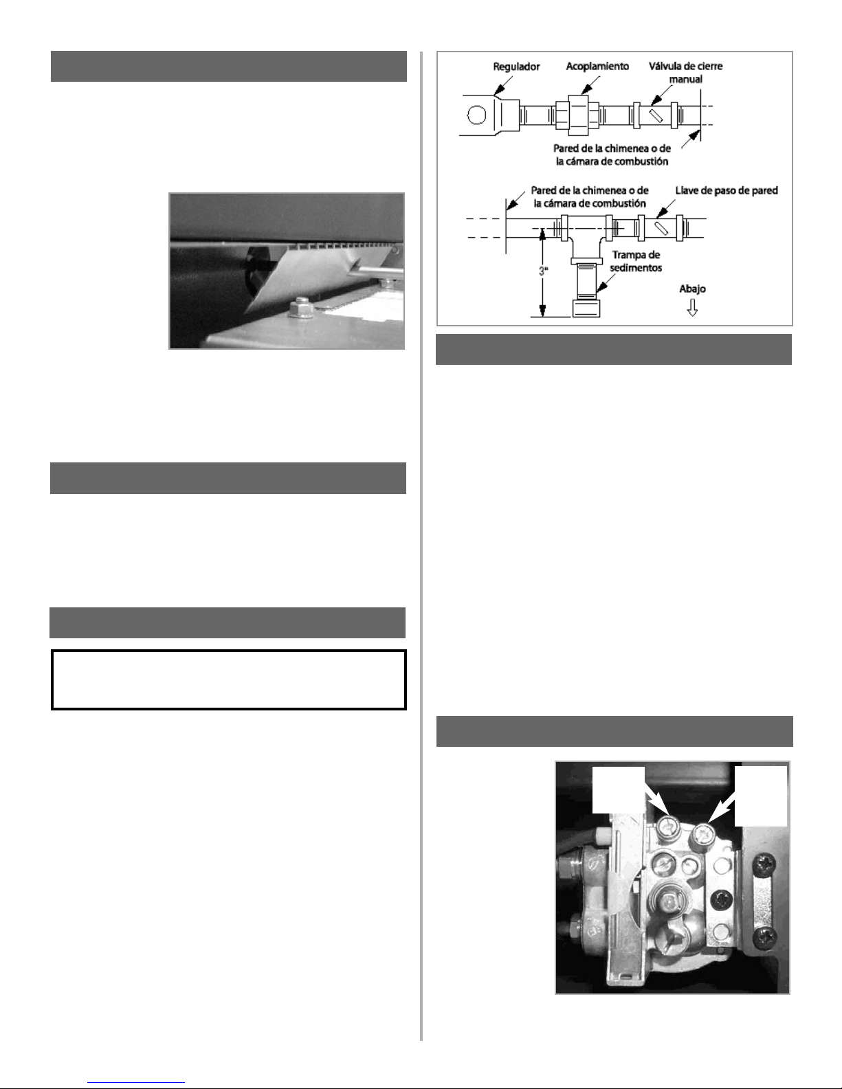
Abra el suministro de gas y verifique que no hay fugas usando una solución
para detectar fugas de gas (también conocida como detector de burbujas).
NOTA: El uso de una solución de agua jabonosa (50% jabón de mano, 50%
agua) es una solución eficaz para buscar fugas, pero no se recomienda
porque el residuo de jabón que queda en las tuberías y los acoplamientos
puede producir corrosión con el tiempo.
A. Encienda el aparato (consulte la etiqueta de instrucciones de encendido del
compartimento de control o de la página 22).
B. Con un cepillo, cubra todas las juntas y conexiones con la solución para
pruebas de fugas de gas para verificar que no hay fugas. Si se forman
burbujas, o se detecta olor a gas, haga girar la perilla de control del gas
(apagado/piloto/encendido) hasta la posición de “APAGADO” (OFF).
Apriete o vuelva a montar la conexión que tiene la fuga, luego vuelva a
comprobar lo segundo descrito anteriormente.
C. Cuando haya probado las tuberías de gas y comprobado que no tienen
fugas, asegúrese de limpiar la solución de prueba de fugas.
D. Observe las llamas individuales del quemador. Asegúrese de que todos los
orificios están abiertos y que producen llamas homogéneas en todo el
quemador. Si algún orificio está obstruido total o parcialmente, límpielo.
La presión debe
comprobarse con el
calentador encendido
y el control puesto en
llama alta.
El regulador de
presión de los
modelos manuales
está preajustado y
bloqueado para evitar
su manipulación
indebida. Si la presión
no es la especificada
en la sección 2
"Especificaciones del
aparato" de la página
14, sustituya el
regulador por la pieza
número FT/F730031. Después de medir la presión, vuelva a colocar los
tornillos del punto de prueba y asegúrese de que no haya fugas de gas.Todas
las instrucciones deben ser entregadas al usuario para su conservación.
Si se va a realizar una conexión de gas oculta, asegúrese de que la tubería
de suministro de gas está en su posición final y que puede introducirse en el
aparato correctamente una vez que el aparato esté colgado en la pared.
Introduzca los tornillos de montaje en los tacos de pared superiores, teniendo
cuidado de dejar las cabezas de los tornillos a 3/8” aproximadamente de la
pared. Ahora cuelgue
el aparato en estos
tornillos a través de los
dos orificios con forma
de bocallave situados
en el panel trasero del
aparato.
Antes de apretar del
todo los tornillos de
montaje, se
recomienda
comprobar la
alineación horizontal del aparato usando un nivel, puesto que todavía es
posible realizar pequeños ajustes si es necesario. Cuando lo haya
comprobado, apriete del todo los cuatro tornillos de fijación.
Para acceder a los tornillos de fijación superiores, introduzca un destornillador
a través de los orificios de las placas deflectoras situadas por encima del
catalizador, según muestra la Figura 7.
No hay componentes de lecho de combustible de imitación que instalar. El
aparato tiene un quemador tipo cinta que ha sido diseñado para producir una
banda continua de llamas en toda su longitud. Inspeccione visualmente el
quemador para asegurarse de que está libre de elementos extraños. Si es
necesario limpiar o quitar el polvo del quemador, debe desmontarse la puerta
de vidrio retirando sus cinco tornillos de retención. Vuelva a montar la puerta
de vidrio después de la limpieza o inspección, comprobando su estanqueidad.
Un instalador calificado de aparatos de gas debe conectar el calentador de
gas al suministro de gas.
Consulte todas las normas locales. Enrute la tubería de gas usando las
técnicas y los materiales especificados en las normas locales y/o nacionales.
Utilice únicamente tuberías de 1/2” o más de diámetro para asegurar el
caudal necesario de gas a la chimenea. Si la tubería es demasiado pequeña,
habrá una pérdida excesiva de presión.
Deben instalarse, aguas arriba del calentador, una válvula de cierre manual
con homologación ANSI, dentro del hueco de la chimenea, si se utiliza tubería
rígida. Asegúrese de que hay una trampa de sedimentos instalada aguas
arriba del calentador (figura 8), dentro del sistema de tuberías de la estructura,
para evitar que pasen humedad y contaminantes a través del tubo a los
controles y al quemador del calentador. Si no, el calentador puede no
funcionar de manera confiable.
La conexión de entrada de gas del calentador es de 3/8” NPT en el regulador,
ubicado debajo del quemador, en el centro del calentador. Al apretar el
acoplamiento con el regulador, sujete firmemente el regulador con una llave
para evitar que éste se mueva.
18
11.0
CONEXIÓN DE UN CONDUCTO DE GAS
12.0 COMPROBACIÓN DE LAS CONEXIONES DE GAS
IMPORTANTE: SUJETE EL REGULADOR DEL CALENTADOR
CON UNA LLAVE PARA EVITAR QUE SE MUEVA AL
CONECTARLO A LA TUBERÍA DE ENTRADA.
13.0 COMPROBACIÓN DE LA PRESIÓN DEL GAS
Presión del
quemador
(colector)
Ajuste de
la presión
del
regulador
Figura 9
9.0 MONTAJE DEL APARATO - (cont.)
Figura 7
10.0
COMPROBACIÓN DEL QUEMADOR
Figura 8
Page 19
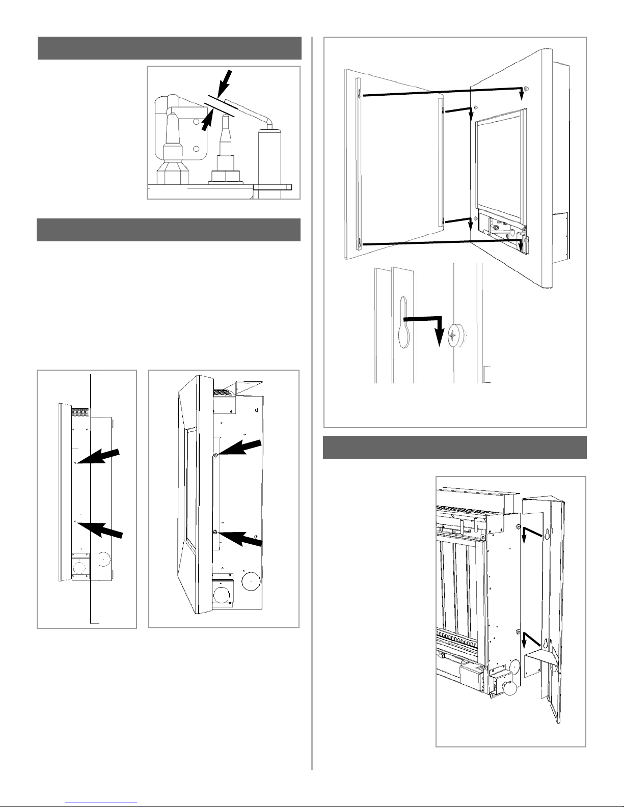
El hueco entre el electrodo y
el piloto debe ser de 1/8” a
3/16” para producir una
buena chispa. No debe ser
necesario ajustar este hueco.
Si por alguna circunstancia el
encendido piezoeléctrico
falla, el piloto no puede ser
encendido manualmente.
Todas las instrucciones
deben ser entregadas al
usuario para su conservación. Enseñe al cliente a encender y controlar el calentador.
Modelos Athos: El marco delantero se fija a la cámara de combustión usando
cuatro tornillos autorroscantes (dos en cada lado) según se indica en la Figura
12. Asegúrese de empujar hacia arriba el marco para que los bordes internos
del mismo estén totalmente en contacto con el marco de acero inoxidable.
Modelos Reflection: La sección delantera del conjunto del marco debe ser
colocada ahora. Retire el conjunto de marco extrusionado del embalaje.
Posicione el marco en la parte delantera de la chimenea, asegurándose de
empujar hacia arriba el marco para que los bordes internos del mismo estén
totalmente en contacto con el marco de acero inoxidable. Introduzca cuatro
tornillos de autorroscantes en las posiciones de los laterales de la cámara de
combustión según se indica en la Figura 11.
Modelos Scandium y
Neon: El panel decorativo de vidrio se sujeta con cuatro tornillos M6 que
sobresalen de la parte delantera de la carcasa. Introduzca los tornillos de
fijación M6 y asegúrese de que sobresalen unos 1/8” para poderlos introducir
en los orificios en forma de bocallave, y enganche el panel. Asegúrese de que
los tornillos están correctamente introducidos en los orificios en forma de
bocallave.
19
15.0 INSTALACIÓN FINAL DEL CONJUNTO DEL MARCO
14.0 ESPACIO ENTRE ELECTRODOS
Figura 10
Espacio entre
electrodos
Figura 11
Figura 12
Modelo Neon ilustrado como ejemplo
Figura 13
16.0 COLOCACIÓN DE LOS PANELES LATERALES
Modelos Athos, Scandium y Neon solamente
Retire los dos conjuntos de
panel lateral del embalaje
protector y móntelos en los
laterales de la cámara de
combustión según se
indica. Introduzca los
tornillos de fijación M6 en
los laterales de la cámara
de combustión y asegúrese
de que sobresalen unos
2 mm para poderlos
introducir en los orificios en
forma de bocallave, y
enganche los paneles
laterales.
Nota: El panel decorativo delantero
no se muestra para mayor claridad.
Figura 14
Page 20
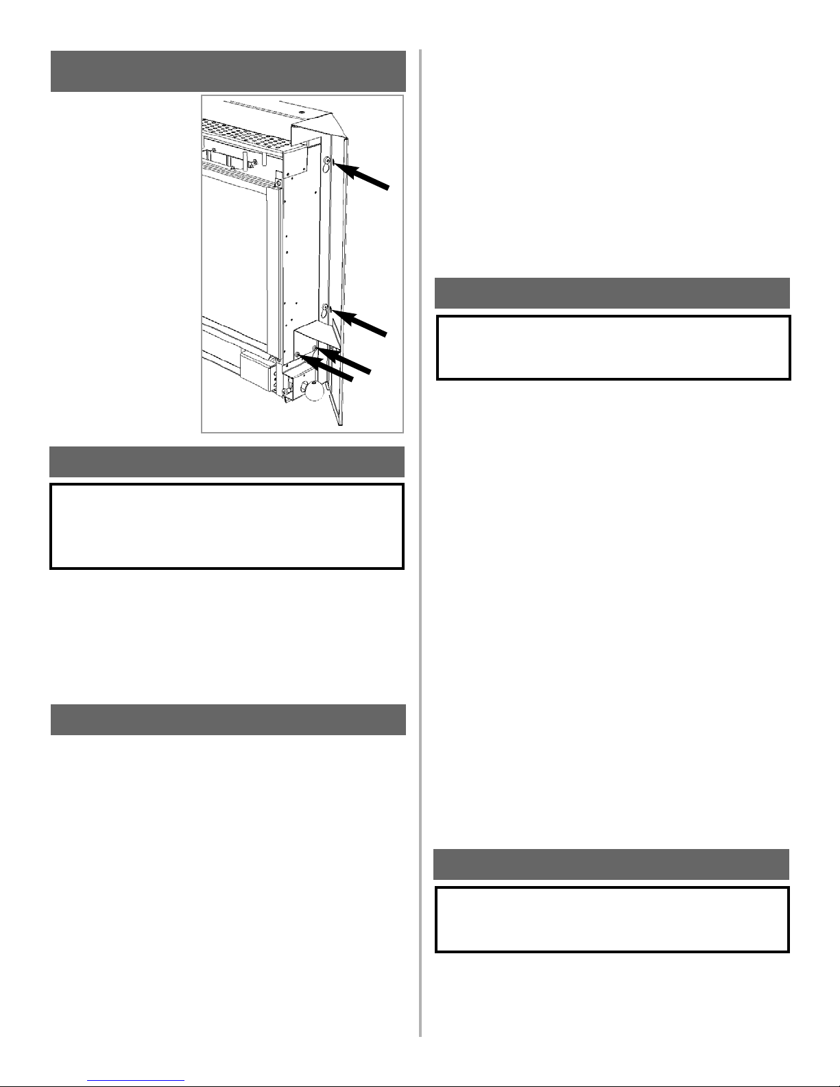
Introduzca un destornillador a
través de los orificios del
panel de la derecha y apriete
los dos tornillos de fijación M6
(tornillos ‘a’ en el diagrama
anterior). Luego introduzca
dos tornillos autorroscantes
Nº 8 (tornillos ‘b’ en el
diagrama anterior) a través
del soporte del panel lateral y
de los orificios correspondientes de la cámara de
combustión. Apriete a fondo.
Repita para el panel de la
izquierda, que se fija
apretando los tornillos M6 ‘a’
solamente.
El panel de la derecha tiene
un panel abisagrado
(modelos Scandium y Neon)
para permitir el acceso a la
perilla de control.
Avise al cliente que puede limpiar el calentador cuando éste está frío usando
un paño húmedo y un detergente suave en la mayoría de las superficies.
Avísele que el calentador emitirá un “olor a nuevo” durante cierto tiempo
después de la puesta en marcha inicial y que puede ser necesario una
ventilación adicional durante este periodo. Recomiéndele que utilice una
pantalla para proteger a niños, animales domésticos, y personas ancianas y
enfermas.
Aísle el calentador del suministro de gas. Asegúrese de que el calentador se
ha enfriado totalmente antes de proceder al mantenimiento. El procedimiento
de mantenimiento recomendado es el siguiente:
1. Disponga el paño de protección y las herramientas.
2. Retire la sección delantera del marco siguiendo las indicaciones de
la sección 8.0:
3. Retire el conjunto de la puerta de vidrio (5 tornillos) y límpielo con
cuidado.
4. Inspeccione el quemador y los catalizadores y límpielos si es
necesario con un cepillo suave.
5. Desconecte el suministro de gas.
6. Retire los 4 tornillos que sujetan los soportes del quemador a la
base y a la parte trasera de la cámara de combustión. Retire los
dos tornillos que sujetan el soporte del regulador, en la parte
inferior de la cámara de combustión.
7. Retire la unidad del quemador, desmonte los tubos del quemador y
limpie a fondo.
8. Limpie el restrictor en línea, el conjunto del piloto y el tubo del
quemador. No intente retirar el inyector del piloto, puesto que
podría causar daños.
9. Vuelva a montar los componentes.
10. Abra el paso de gas y compruebe que no hay fugas. Compruebe
que el piloto y el quemador se encienden correctamente.
11. Vuelva a colocar el conjunto de la puerta de vidrio, comprobando
su estanqueidad.
12. Vuelva a colocar la carcasa. Para volver a colocarla, siga en
orden inverso el procedimiento de retirada explicado en la sección
8.0.
13. Compruebe que la ventilación integrada no está obstruida.
14. Encienda el calentador y compruebe las presiones.
15. Compruebe que el aparato funciona de manera segura.
Consulte las secciones correspondientes si necesita instrucciones de
mantenimiento específicas.
Primero, retire la sección delantera del marco (ver la sección 8.0), el panel
de vidrio, y desconecte el suministro de gas dentro del aparato. Ahora
pueden liberarse las conexiones de gas a la válvula de gas. Retire los cuatro
tornillos que sujetan el quemador. Retire el clip de retención del husillo de la
perilla de control, y retire el conjunto de la perilla de control.
Retire los tubos del piloto y del quemador principal y sople a través de los
mismos para desprender cualquier residuo. Ahora retire el codo del inyector y
sople a través del mismo para asegurarse de que quede completamente libre
de obstrucciones.
Desenganche el filtro de malla del piloto y límpiela con un cepillo suave.
Limpie el exterior del conjunto del piloto con un cepillo suave y sople por los
orificios de las llamas en el cabezal del piloto. Compruebe que los orificios de
aireación están libres de pelusas y suciedad. Si es necesario, el conjunto del
piloto puede retirarse desconectando el cable de alta tensión del electrodo y
el tubo de gas, y desatornillando los tornillos de montaje. El conjunto del piloto
no admite mantenimiento y no debe desmontarse. Los orificios de aireación
deben estar completamente libres de obstrucción por dentro para una
operación correcta. NUNCA MODIFIQUE NI DOBLE EL TERMOPAR PARA
HACER QUE EL PILOTO SE MANTENGA ENCENDIDO. Las modificaciones
son peligrosas y pueden tener graves efectos no visibles en la seguridad. Si
el piloto no permanece encendido, hay un problema con la suciedad o con el
suministro de gas, o el termopar debe ser sustituido.
La válvula de gas es un elemento que no admite mantenimiento. Si es
necesario sustituirla, retire la placa indicativa y luego el tornillo que sujeta el
soporte de la válvula, retire todos los acoplamientos de tubos, y la válvula
completa. Debe sustituirse con piezas del fabricante original.
Vuelva a montar las piezas en orden inverso. Compruebe que las presiones
son las indicadas en la Sección 3: Especificaciones del aparato.
Retire la carcasa, el panel de vidrio y el conjunto del quemador (según lo
indicado en la sección de mantenimiento), el filtro de malla y el conjunto del
piloto usando un destornillador para retirar los tornillos restantes.
Limpie el conjunto del piloto con un cepillo suave y sople a través del mismo.
Compruebe que los orificios de aireación están libres de pelusas y suciedad.
20
17.0 INFORMACIÓN AL CLIENTE
ADVERTENCIA: NO AÑADA TRONCOS U ELEMENTOS
DECORATIVOS TALES COMO PIÑAS, VERMICULITA O
LANA MINERAL. EL USO DE ESTOS ELEMENTOS ADICIONALES PUEDE CAUSAR LA GENERACIÓN DE HOLLÍN.
18.0
MANTENIMIENTO
19.0 MANTENIMIENTO DEL QUEMADOR
ADVERTENCIA: CUALQUIER MODIFICACIÓN DE ESTE
APARATO Y/O SUS CONTROLES DE OPERACIÓN PUEDE
SER PELIGROSO.
16.0 COLOCACIÓN DE LOS PANELES LATERALES
(cont.)
‘a’
‘a’
‘b’
‘b’
20.0 CONJUNTO DEL PILOTO
ADVERTENCIA: NO DEBEN EFECTUARSE AJUSTES EN EL
SISTEMA DE PILOTO ODS. LA MANIPULACIÓN DE ESTE
SISTEMA PUEDE SER EXTREMADAMENTE PELIGROSA.
Figure 15
Page 21
Limpie a fondo el interior; es posible retirar el conector de la base del conjunto
del piloto usando dos llaves para facilitar la limpieza. No dañe el inyector del
piloto, ni intente desmontarlo.
El conjunto es preajustado en fábrica, y la única comprobación necesaria es
asegurar que el espacio entre electrodos es correcto. Consulte las
especificaciones para el ajuste de gas.
NUNCA MODIFIQUE NI DOBLE EL TERMOPAR PARA HACER QUE EL
PILOTO SE MANTENGA ENCENDIDO. Si el piloto no permanece encendido,
hay un problema de suciedad o con el suministro de gas, o el termopar debe
ser sustituido. Las modificaciones son peligrosas y pueden tener graves
efectos no visibles en la seguridad; por tanto, NO DEBEN hacerse. Debe
sustituirse con piezas del fabricante original. Vuelva a montar las piezas en
orden inverso. Compruebe que las presiones son las indicadas en la
Sección 3: Especificaciones del aparato
Se recomienda inspeccionar los catalizadores en busca de señales de daños
y suciedad durante los procedimientos de mantenimiento de rutina. La vida
prevista de los catalizadores es de más de 11.000 horas (10 años de uso
normal). Después de este tiempo es necesario cambiar el catalizador.
Si hay acumulaciones de suciedad u hollín en los catalizadores, deben
limpiarse con un cepillo suave y una aspiradora. Si se retiran para su limpieza,
asegúrese de que las juntas están en buenas condiciones antes de volver a
instalar el catalizador. Normalmente se necesitarán juntas nuevas.
El rendimiento del catalizador puede comprobarse usando un analizador de
gases de combustión, según se explica a continuación.
Importante: La temperatura de los gases emitidos por los convertidores
catalíticos supera los 700
o
F. La medición de gases a esta temperatura puede
dañar algunos tipos de analizadores de gases. En caso de duda, consulte al
fabricante del equipo.
Encienda la chimenea siguiendo las instrucciones de uso, y deje que funcione
durante 15 minutos. Ponga la sonda del analizador de gas directamente
encima de un catalizador a través de la rejilla de salida, en la parte superior
del aparato. Anote la concentración de dióxido de carbono (CO2) y luego la
concentración de monóxido de carbono (CO) mostradas por el analizador, así
como las unidades en que se muestran los valores. La mayoría de los
analizadores muestra las concentraciones de dióxido de carbono (CO2) en
porcentajes (%) y las de monóxido de carbono en partes por millón (ppm).
Para calcular la razón de combustión del aparato (CO/CO2) es necesario
primero expresar ambas concentraciones de gas como porcentaje. Para
convertir desde partes por millón (ppm) a un porcentaje (%) divida la figura en
ppm por 10.000. Ejemplos: 35ppm = 0,0035%, 15ppm = 0,0015%, 5ppm =
0,0005%.
Ahora, divida la concentración de monóxido de carbono (CO) expresada como
porcentaje por la concentración de dióxido de carbono (CO2) para obtener la
razón de combustión del aparato.
La razón de combustión de los gases emitidos por el convertidor catalítico no
debe superar 0,0015.
En caso de sustitución, primero retire el marco decorativo según lo indicado
en la Sección 15.0. Los catalizadores se encuentran encima de la cámara de
combustión interna, y pueden retirarse desatornillando las tuercas de
retención de la placa de sujeción. Retire el catalizador y su junta, y
deséchelos.
Coloque un catalizador nuevo y las juntas correspondientes en orden inverso,
asegurando que el catalizador y la puerta queden estancos.
Si un aparato tiene varios años de antigüedad o ha sido desmontado varias
veces, es necesario comprobar su estanqueidad. Es importante que todos los
productos de la combustión pasen a través de los convertidores catalíticos
situados en la parte superior de la cámara de combustión antes de salir del
aparato.
Caliente la cámara de combustión encendiendo el aparato durante unos
minutos para generar un flujo de aire a través de la cámara de combustión.
Apague el quemador e introduzca una pastilla de humo o un fósforo en la base
del calentador, debajo de la bandeja del quemador. Saldrán grandes
cantidades de humo de la parte superior del aparato, pero no debe salir humo
de las uniones o de las juntas, sobre todo alrededor de la puerta. Es
importante observar que el aparato nunca podrá ser estanco al humo al 100%,
y podrán verse pequeñas cantidades de humo en esquinas, uniones y juntas,
incluso con la chimenea encendida, sin afectar la seguridad.
PANEL DE VIDRIO -Puede limpiarse con un limpiador para cristales
apropiado, o con un limpiador comercial para encimeras de vitrocerámica.
Pruebe primero en una zona pequeña.
ZONAS PINTADAS - Pueden limpiarse con un paño seco.
ZONAS DE ACERO INOXIDABLE - Pueden limpiarse usando un limpiador
comercial para acero inoxidable o aceite para niños. Haga pruebas en una
pequeña zona oculta del acero inoxidable antes de limpiar. Limpie siempre en
el sentido del “veteado”.
21
21.0 CATALIZADORES
CO (%)
CO2 (%) = ratio
22.0 COMPROBACIÓN DE FUGAS DE LA CÁMARA DE
COMBUSTIÓN
23.0 LIMPIEZA
ADVERTENCIA: APAGUE EL CALENTADOR DE GAS SIN SALIDA
DE HUMOS Y DEJE QUE SE ENFRÍE ANTES DE LIMPIARLO.
20.0 CONJUNTO DEL PILOTO - (cont)
Page 22
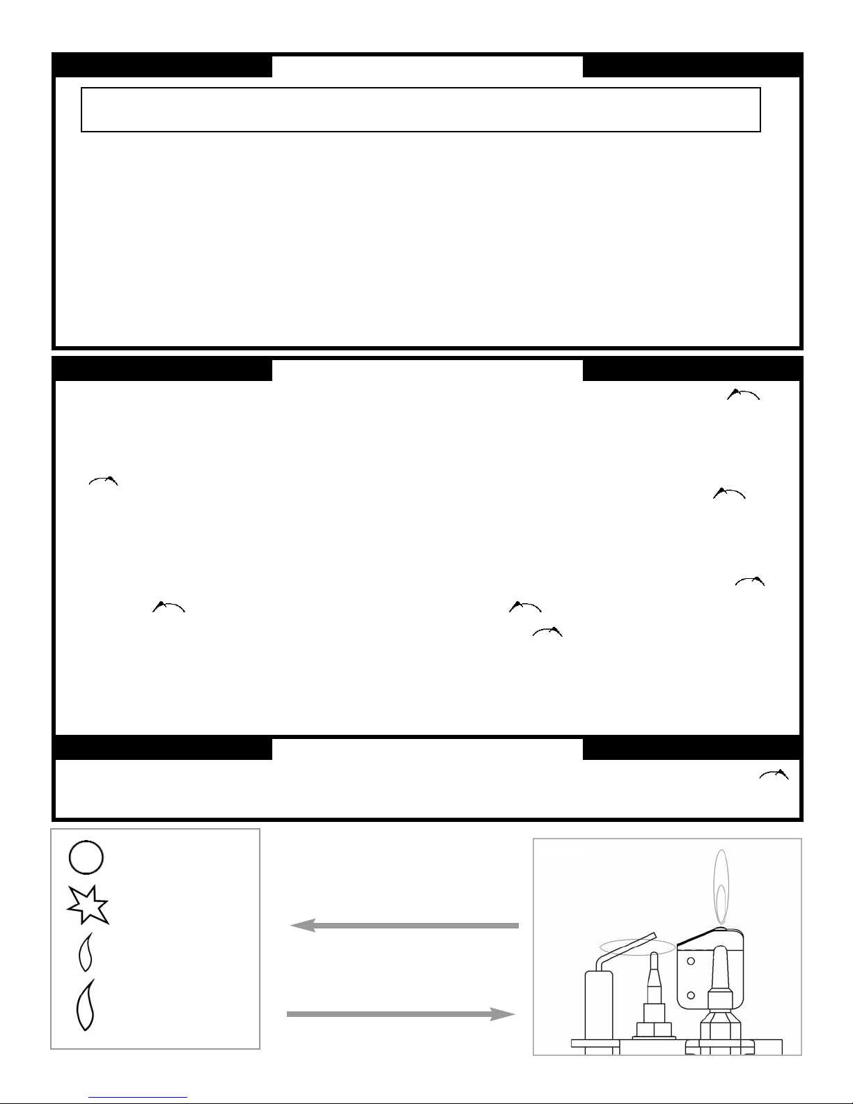
Figura 16: La perilla de control está situada en el
lado derecho inferior de la carcasa. Tiene forma
esférica y lleva los rótulos indicados en el
diagrama de la izquierda;
Figura 17 :Conjunto del piloto. Está situado detrás
del quemador, en el lado izquierdo del aparato.
Figura 17
22
Posición APAGADO
Posición CHISPA
Posición BAJO
Posición ALTO
PARA SU SEGURIDAD, LEA ANTES DE ENCENDER EL APARATO
ADVERTENCIA: SI USTED NO OBSERVA ESTRICTAMENTE ESTAS INSTRUCCIONES, PUEDE PRODUCIRSE UN INCENDIO O
UNA EXPLOSIÓN, CON RESULTADO DE DAÑOS MATERIALES, LESIONES PERSONALES O PÉRDIDA DE LA VIDA.
A. El calentador tiene un piloto que debe ser encendido manualmente.
Para encender el piloto, siga estas instrucciones exactamente.
B. ANTES DEL USO examine toda la zona del calentador y verifique si
hay olor a gas. Asegúrese de oler cerca del piso, porque algunos
gases son más pesados que el aire y se asientan sobre el piso.
QUÉ HACER SI USTED NOTA OLOR A GAS
• No intente encender ningún aparato.
• No toque ningún interruptor eléctrico; no utilice ningún teléfono de
su edificio.
• Llame inmediatamente a su compañía de gas desde el teléfono de
un vecino. Siga las instrucciones de la compañía de gas.
• Si no puede contactar con su compañía de gas, llame a los bomberos.
C. Utilice únicamente la mano para presionar o hacer girar la perilla de
gas.
No utilice nunca herramientas. Si no es posible presionar o hacer girar
la perilla con la mano, no intente repararlo; llame a un técnico de
mantenimiento calificado. El uso de la fuerza o cualquier intento de
reparación puede causar un incendio o una explosión.
D. No utilice este calentador si cualquier parte del mismo ha estado
sumergida en agua. Llame inmediatamente a un técnico de
mantenimiento calificado para que inspeccione el aparato y cambie
cualquier pieza del sistema de control y cualquier control de gas que
haya estado sumergido en agua.
23.0 INSTRUCCIONES DE ENCENDIDO
8. Continúe haciendo girar en el sentido contrario a las agujas del reloj,
pasando por el clic de la chispa, hasta la posición PILOT, y compruebe que el piloto
se ha encendido. Si no, haga girar la perilla de control en el sentido de las agujas
del reloj hasta que haga tope, y repita la secuencia.
9. Mantenga presionada la perilla durante 10 segundos más para evitar que el
detector de fallo de la llama cierre el paso de gas mientras se caliente la sonda.
10. Deje salir la perilla mientras la hace girar a la posición deseada.
Cierre el panel de acceso a la perilla de control.
• Si la perilla no sale, desista y llame inmediatamente a su técnico de mantenimiento
o a su compañía de gas.
• Si después de varios intentos el piloto no permanece encendido, presione la
perilla de gas y hágala girar en el sentido de las agujas del reloj a “OFF”;
espere 30 segundos. Presione la perilla y hágala girar en el sentido contrario a las
agujas del reloj a “IGN”; luego presione otra vez el botón de encendido.
Si el piloto no se vuelve a encender, presione la perilla y hágala girar en el sentido
de las agujas del reloj a “OFF”, y llame a su técnico de mantenimiento o a
la compañía de gas.
11. Espere 30 segundos antes de volver a ajustar el calentador después de mover la
perilla de control a un ajuste más bajo.
24.0 CÓMO CERRAR EL PASO DE GAS AL APARATO
2. Presione la perilla y hágala girar en el sentido de las agujas del reloj
a la posición “OFF” (Figura 16). Cierre el panel de acceso a la perilla de
control.
1. Abra el panel de acceso a la perilla de control.
1. ¡Pare! Lea la información sobre seguridad de la sección anterior.
2. Asegúrese de que la válvula de cierre manual está completamente abierta.
3. Abra el panel de acceso a la perilla de control.
4. Presione la perilla de control y hágala girar en el sentido de las agujas del reloj
a la posición “OFF” (Figura 16).
5. Espere 5 minutos para eliminar cualquier resto de gas. Luego compruebe si hay
olor a gas, incluyendo cerca del piso. Si nota olor a gas, ¡PARE! Siga las
instrucciones de seguridad de la sección “Qué hacer si usted nota olor a gas” en
la Sección ‘B’ anterior. Si no nota olor a gas, continúe con el paso siguiente.
6. El piloto está situado en el lado izquierdo, debajo del quemador (Figura 17).
7. Presione la perilla hacia dentro y hágala girar en el sentido contrario a las
agujas del reloj a la posición “SPARK” (Figura 16), y manténgala
presionada en esa posición durante unos segundos.
Nota: Al encender el calentador por primera vez será necesario mantener la perilla
presionada hasta el fondo durante unos 30 segundos para purgar todo el aire de
las tuberías de gas.
Figura 16
Page 23

23
Se produce una chispa pero el piloto No llega el gas: compruebe que los aisladores están abiertos.
no se enciende Tubería obstruida: limpiar.
El aire no se ha purgado del todo: vuelva a purgar el aire, o espere más tiempo.
Derivación de la chispa a una pieza metálica: ajuste correctamente el espacio entre electrodos.
Piloto obstruido: limpiar internamente.
El piloto se enciende, luego se apaga Importante restricción en el suministro de gas: eliminar la obstrucción.
Termopar defectuoso: cambie el conjunto del piloto.
Piloto obstruido: limpiar.
Filtro de malla obturado: limpiar
Mantenga pulsado la perilla de control durante más tiempo.
Compruebe que la perilla de control no choca con la placa de datos.
Si el piloto no permanece encendido, hay un problema de suciedad o con el suministro de gas, o el
termopar debe ser sustituido. Las modificaciones son peligrosas y pueden tener graves efectos no visibles
en la seguridad. NUNCA MODIFIQUE NI DOBLE EL TERMOPAR PARA HACER QUE EL PILOTO SE
MANTENGA ENCENDIDO.
No se produce una chispa en el piloto Cable de alta tensión suelto: reconectar.
Compruebe el espacio entre electrodos (ver Sección 15.0).
Unidad piezoeléctrica defectuosa: cambiar.
Cortocircuito en el electrodo: limpiar.
Derivación de la chispa a piezas metálicas debajo de la bandeja: volver a alinear el cabezal de alta
tensión.
El calentador funciona durante un tiempo, Termopar suelto o defectuoso: rectificar.
luego se apaga Piloto obstruido: limpiar.
Suciedad o pelusas en el orificio de aireación del piloto o en el filtro de malla: limpiar a fondo.
Si el piloto no permanece encendido, hay un problema de suciedad o con el suministro de gas, o el
termopar debe ser sustituido. Las modificaciones son peligrosas y pueden tener graves efectos no visibles
en la seguridad. NUNCA MODIFIQUE NI DOBLE EL TERMOPAR PARA HACER QUE EL PILOTO SE
MANTENGA ENCENDIDO.
La llama del piloto se reduce cuando Flujo defectuoso de gas al calentador: compruebe la presión con el calentador en Alto.
el calentador está en Alto Si la presión es baja, elimine cualquier restricción en la tubería o la válvula.
Compruebe que todos los aisladores son del tamaño correcto y que están totalmente abiertos.
Compruebe que hay suficiente presión en el contador.
Si el piloto no permanece encendido, hay un problema de suciedad o con el suministro de gas, o el
termopar debe ser sustituido. Las modificaciones son peligrosas y pueden tener graves efectos no visibles
en la seguridad. NUNCA MODIFIQUE NI DOBLE EL TERMOPAR PARA HACER QUE EL PILOTO SE
MANTENGA ENCENDIDO.
Hay olor a gas al encenderse o utilizarse Olor “a nuevo” del aparato.
el calentador por primera vez Fuga. Realice prueba de fugas y resuelva cualquier problema.
Materiales utilizados en lugares no apropiados.
25.0 GUÍA DE SOLUCIÓN DE PROBLEMAS
26.0 PIEZAS DE REPUESTO
Descripción Pieza número
Conjunto de puerta de vidrio FB/F960004
Válvula de gas FT003155/0
Catalizador FB/f780079
Conjunto de piloto FT/F730023
Conjunto de quemador TRAY052
Kit de junta para catalizador IN/F940136
Regulador de la presión de entrada FT/F730031
Marco decorativo delantero FR/F550097
Marco decorativo trasero FR/F550098
Al pedir piezas de repuesto, proporcione siempre la siguiente información;
1. El número de modelo del calentador.
2. El número de serie del calentador.
3. El número de pieza.
4. La descripción de la pieza.
5. La cantidad solicitada.
6. La fecha de instalación del calentador.
Si usted encuentra problemas, necesita piezas de repuesto o tiene alguna
pregunta sobre la instalación del calentador, diríjase a;
Focal Point (North America)
5555 Pleasantdale Road
Doraville, Georgia 30340
Teléfono gratuito: 1 800 704 6093
Fax: 770 368 8261
E-mail: [email protected]
Fabricado por:
Focal Point Fires plc.
Christchurch, Dorset
Reino Unido BH23 2BT
Page 24
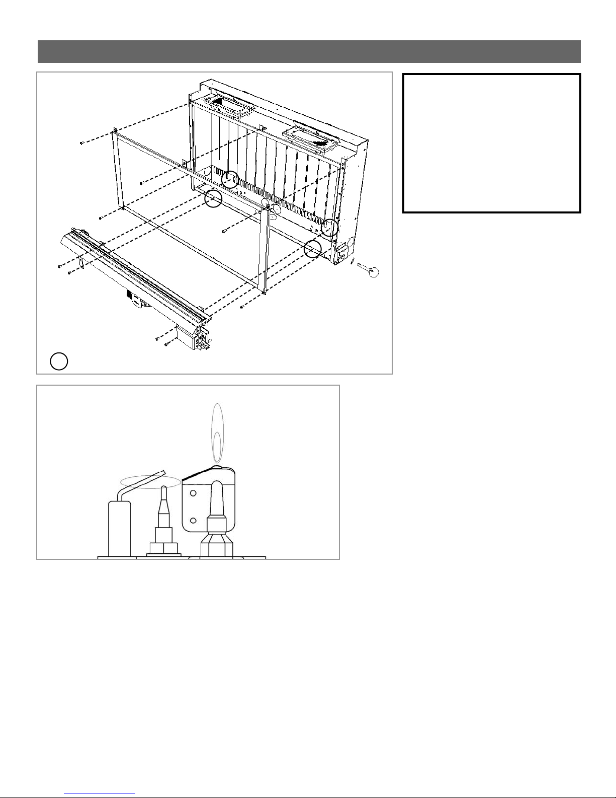
24
Figura 19
Figura 18: Remoción y reinstalación del
conjunto de la puerta de vidrio y el conjunto
del quemador..
Figura 19: Comprobación visual
de la llama del piloto.
ADVERTENCIA: EL NO UBICAR LAS
PIEZAS EN LOS LUGARES
SEÑALADOS EN ESTOS DIAGRAMAS,
O LA UTILIZACIÓN DE PIEZAS NO
HOMOLOGADAS OFICIALMENTE PARA
EL USO CON ESTE CALENTADOR
PUEDEN CAUSAR DAÑOS
MATERIALES O LESIONES
PERSONALES.
Puesto que nuestra política es de mejora y desarrollo continuos, esperamos que usted entienda que debemos reservarnos el derecho a modificar detalles y/o especificaciones sin previo aviso.
DO005566/0
28.0 UBICACIÓN DE PIEZAS SUSTITUIBLES IN SITU
Figura 18
indica 4 puntos de fijación del quemador
 Loading...