


INSTALLATION AND USER INSTRUCTIONS
All instructions must be handed to user for safekeeping
Revision A - 07/08
Country(s) of destination - GB/IE
EVOKE
LCD ELECTRIC WALL HEATER
MODEL : L23LCD
Focal Point Fires plc, Christchurch, Dorset BH23 2BT
Tel: 01202 499330 Fax: 01202 499326
www.focalpointfires.co.uk
e-mail: sales@focalpointfires.co.uk

‘Evoke’
154
503
21
431
480
269
800
421
400
350
© 2008 Focal Point Fires plc.
Appliance Dimensions
Figure 1
Please note : Except where otherwise stated, all rights, including copyright in the text, images and layout of this booklet is owned by Focal
Point Fires plc. You are not permitted to copy or adapt any of the content without the prior written permission of Focal Point Fires plc.

CONTENTS
PRELIMINARY NOTES
The Evoke Electric Wall Heater provides convected heating in conjunction with a LCD screen which can display a number
of different fuel effects and scenes. The appliance is designed for indoor use, and can be simply wall mounted in the majority of wall positions anticipated. It can can be located in any household room, with the exception of bathrooms. Read all of
the instructions before commencing installation. Retain for future reference and pass on as necessary to subsequent owners
of the appliance.
DO NOT use this appliance immediately below a fixed socket outlet.
DO NOT use this appliance in the immediate vicinity of a bath, shower, swimming pool or other area where water/moisture
could present a hazard.
CAUTION: This appliance must not be used in conjunction with any timer, programmer or thermal control, or any other
device that will switch on the appliance automatically, as a fire risk may occur if the heaters are accidentally covered or displaced.
Do not allow the heater to be covered as this may cause overheating. The appliance must not be placed near curtains or similar material. A clearance space of at least 500mm should be allowed in front of the appliance.
The electrical socket that the appliance uses MUST be easily accessible. Do not route the supply cord directly over or above
the heater unit. If the cord is damaged, it must be replaced by a service agent or competent person.
This appliance is not intended for use by persons (including children) with reduced physical, sensory or mental capabilities,
or lack of experience and knowledge, unless they have been given supervision or instruction concerning use of the appliance by a person responsible for their safety. Children should be supervised to ensure that they do not play with the appliance.
APPLIANCE DATA
ELECTRICAL INSTALLATION REQUIREMENTS
The appliance is designed to be wall mounted using the wall mounting plate and fixings provided.
DO NOT RECESS ANY PART OF THE APPLIANCE.
The appliance is supplied with a pre-wired three pin BS1363 plug (13 Amp fuse rated), and 2 metre cable. A standard
switched outlet/wall socket, (including earth provision), must therefore be located within this distance, and be easily accessible in order to isolate the supply for maintenance and cleaning. This socket
must not
be mounted behind or above the
appliance.
IMPORTANT: THIS APPLIANCE MUST BE EARTHED.
1
Section Contents Page No.
1.0 Preliminary Notes 1
2.0 Appliance Data/Specifications 1
3.0 Electrical Installation Requirements 1
4.0 Site Requirements 2
5.0 Clearances to Combustible Materials 2
6.0 Unpacking the Appliance 2
7.0 Component Checklist 2
1.0
Section Contents Page No.
8.0 Fixing the Appliance 3
9.0 Operating the Appliance 4
10.0 Safety Cut-Out System 5
11.0 Maintenance 6
12.0 Cleaning 6
13.0 Servicing 6
Weight (kg): 10.0 kg
Dimensions (mm): H 480 x W 800 x D 154
Voltage (Volts): 230-240V a.c. 50Hz
Heating Elements: 2 x 900/1000 Watts
Supply Cord: 2 metres
Supply Plug: BS 1363, 13A Fused
Location: Indoor Use
LCD Display: 60 Watts
2.0
3.0
© 2008 Focal Point Fires plc.

SITE REQUIREMENTS
The appliances are designed to be wall mounted via the wall mounting plate and fixings provided. The wall should be relatively flat and not interfere with any of the ventilation slots in the appliance casing.
The wall must be structurally sound and of a material capable of withstanding moderate heat. Finished plaster, conventional
wallpaper, dry-lined plaster board are examples of suitable materials. Materials such as “flock blown vinyl”, embossed paper
and cloth wall coverings which are sensitive to even small amounts of heat should be avoided, as some discolouration may
occur. It should be noted that the appliance creates warm convected air currents. These currents move heat from the room
surroundings to, and up the wall surfaces adjacent to the heater.
Installing the heater next to these types of wall coverings or operating the heater where impurities in the air, (such as tobacco smoke) exist, may slightly discolour wall finishing.
If the appliance is to be mounted on a dry lined or timber framed construction then the integrity and ability of the wall to
carry the weight of the appliance must be confirmed. It is important in these circumstances that any vapour barrier and/or
structural members of the house frame are not damaged. If you are unsure of the ability of the wall to carry the weight and/or
which type of wall fixing to use, you should take professional advice and obtain the correct fixings. Alternatively, find a more
suitable wall location.
DO NOT - mount on a ceiling or floor.
- recess any part of the appliance into the wall.
- site any electrical equipment e.g. plasma screen TV sets etc,
on the wall above the appliance.
- site in a position where curtains or drapes could cover the appliance.
- site in a position where other soft materials could cover e.g. below a coat rack.
- site behind an opening door where mechanical impact/damage could occur.
- site where the supply cable would become a trip hazard.
- sit, stand or forcefully pull on the appliance.
- obstruct, cover or force items into the openings.
- use the heater to dry clothes.
- site/use in an outdoor location(s).
- run the supply cable under carpets.
CLEARANCES TO COMBUSTIBLE MATERIALS
It is important that the following clearances are maintained from the appliance to combustible materials and are dependant
on the desired mounting location as defined below.
This appliance is designed to be wall mounted only. Do not stand it on the floor.
The minimum distance from the top of the appliance to a ceiling is 500mm.
The minimum distance to the sides of the appliance is 100mm.
The minimum distance to the front of the applaince is 500mm.
The appliance must not be mounted at floor level. Allow clearance to of 100mm to the floor.
A shelf may me mounted above the appliance provided it meets the requirements for shelfs as detailed below.
UNPACKING THE APPLIANCE
Caution: This appliance is heavy. Always seek assistance whilst unpacking and/or during installation. Read
all
the instructions before continuing to unpack or install this appliance. Carefully remove the appliance from its packaging and lay on the
floor with it`s back surface downward. Check that the remaining packaging contents correlate with the component checklist below. Please dispose of all packaging with care at your local recycling centre.
COMPONENT CHECKLIST
QUANTITY DESCRIPTION
1 Heater unit including LCD display
1 Decorative glass facia
1 Remote control handset
1 Wall mounting plate
1 Mains supply cord
1 Instruction Booklet
4 37mm long round head screws
4 Wall plugs
2
4.0
5.0
Shelf Depth Minimum Shelf Distance
(measured from top of appliance)
2” or (50mm) 11.5 “ or (290mm)
6” or (152mm) 15.4 “ or (390mm)
6.0
7.0
© 2008 Focal Point Fires plc.
FIXING THE APPLIANCE
DO NOT connect the appliance to the supply at this stage.
Remove the single thumbscrew from the middle of the base panel of the appliance, then remove the wall mounting plate from the appliance.
After having selected the final mounting position of the appliance, taking into
account the requirements as specified in sections 3.0, 4.0 and 5.0 of these instructions, the integrity of the wall, and the feasibility of the proposed supply cord routing, the wall mounting plate may be secured to the wall.
To ensure safety, be sure to design the installation so that the strength of both the wall and any wall fixings used are sufficient.
Focal Point Fires plc. assumes absolutely no responsibility for injuries and damages that may occur due to improper installation or handling. The appliance should not be installed until all wet plastering and/or dry wall sanding and wall painting has
been completed. Do not block the ventilation holes of the appliance. The wall onto which the appliance is installed must be
flat. Install only on a vertical surface. Avoid sloped surfaces. Installation onto
anything other than a vertical wall may result in fire, damage or injury.
If the appliance is to be mounted on the inner leaf of a conventional cavity brick
wall, or a solid wall, then the wall plugs and fixing screws provided may be
used. Depending on the condition of the wall it may be necessary to use additional fixings. In this situation, any additional fixings and wallplugs should be of
the same size and type as the ones provided.
Using a spirit level to check correct horizontal alignment, hold the wall mounting plate in the desired position and using a pencil, mark out the position of the
fixing holes on the wall. Remove the mounting plate from the wall and drill four
holes using only a 8.0mm masonry bit to a
depth of 43mm. Insert the wallplugs provided ensuring they are flush to the wall.
Using the screws provided, fix the mounting plate to the wall.
If the appliance is to be mounted on a dry lined wall or a timber framed construction wall
then efforts should be made to fix in at least two positions vertically, into one of the wooden studs, or supporting wooden
members of the wall using two of the fixing screws provided. If this is not achievable then the wall should be strengthened
using appropriate building materials.
If there is no alternative than to rely on
some
plasterboard fixings then special cavity screw fixings or hollow wall anchors will
be required which are not supplied with this
product. These should be constructed from
metal and not plastic and of the design indicated in figure 3.
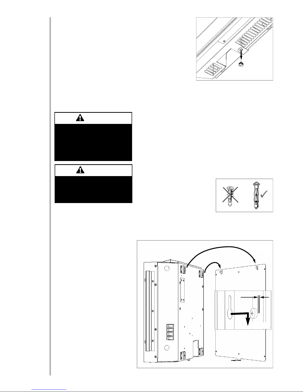
With the wall plate secured in position the
heater unit can be hung onto the wall plate.
Ensure the two hooks at the top of the wall
plate fully engage the keyhole shaped holes
in the brackets at the top of the heater back
panel as shown in figure 4.
Finally re-fit the thumbscrew to the base
panel of the heater via the tab at the bottom
of the wall plate (see figure 2). This fixes the
heater to the wall plate and will prevent the
heater from falling off the wall in the event it
is accidentally knocked, for example.
When the heater unit is in position on the
wall, remove the decorative glass facia from
the packaging and fit to the heater. The four
keyhole shaped holes on the back of the
frame mount directly onto the four M6
screws on the front of the heater (see figure 4a inset).
3
8.0
Figure 3
Figure 2
Figure 4
Plasterboard alone is not considered to
be a structural material.
It is not recommended to rely on plasterboard fixings alone to support the
weight of the appliance.
WARNING
The wall where the appliance is to be
installed must be capable of long-term
support of the total load of the appliance. Measures should also be taken to
ensure sufficient strength to withstand
the force of earthquakes, vibration and
other external forces.
WARNING
© 2008 Focal Point Fires plc.
2mm
Figure 4a

9.0 OPERATING THE APPLIANCE
Read All Instructions Before Use
Check that the heater outlet grille, mounted at the top of the appliance, is not covered or obstructed in any way, and ensure
the power to the fire is switched on. The power to the LCD display panel and the heater functions are controlled using four
switches mounted on the lower right hand side panel.
Controlling the heater functions
The first switch towards the top, marked (0I), controls the main power to the appliance and switches on the LCD display
panel. This feature can be used independently of the heating features.
The next switch down, marked (*) operates the fan blower without heat, and can be used
for cool air circulation. However for this feature, the main power switch (0I), must also be
in the “on” position.
The next switch down, with a “single bar” marked (I) operates the low heat, (1kW), setting.
The switch at the bottom, with “two single bars” marked (II), operates the high heat,
(2kW) setting.
To operate the fire in any of the above modes, the top switch marked (OI) must be
switched to the “on” position.
To operate the fire, the first switch must be turned on firstly, followed by the second
switch to start the blower, if required. To obtain heat from the appliance, the I switch must
then be operated for LOW heat, followed by the II switch for the HIGH heat setting.
Controlling the LCD display panel - Basic functions
The appliance is pre-programmed with seven different scenes as shown in figures 5
through 11. These scenes have been specially edited to run in a seamless loop. When the
appliance is switched on, the coal fire scene will automatically run. To select a different
scene either press the button or the button. This will skip through all of the different scenes in order. Alternatively, to jump directly to a certain scene press one of the
scene select buttons. For example, button will play the log fire scene (see figure 5).
Button will
play the coal fire
scene (see figure
6) and so on.
Certain scenes
also include
sound. This can
be muted by
pressing the
button. The volume can be lowered by pressing
the button
and raised by
pressing the
button.
The footage can
be paused by
pressing the
button. Press
again to resume.
The footage can be speeded up or played backwards by pressing the or buttons.
A clock can be made to appear in the top right hand corner of the screen by pressing .
Press again to hide the clock.
During normal operation the footage may occasionally be seen to ‘freeze’ for a fraction
of a second. This happens as the scene is recycled to loop again. This is perfectly normal
and should be no cause for concern.
Fig. 6 - Log fire
Fig. 11 - Abstract
Fig. 5 - Coal fire
Fig. 7 - Plasma fire (low)
Fig. 8 - Plasma fire (medium)
Fig. 9 - Plasma fire (high)
Fig.10 - River
Figure 12 - Handset basic functions
Clock - on/off
Previous scene
Next scene
Fast forward
Reverse
Mute
Standby/ON
Scene select
Pause/play
Stop
Volume lower
Volume raise
4
1
2
3
4
5
6
7
© 2008 Focal Point Fires plc.

OPERATING THE APPLIANCE - continued
Controlling the LCD display panel - Advanced functions
The LCD display panels are factory set for best all-round performance and no further adjustment should be necessary. Should
you wish however, certain settings can be changed by using some of the buttons on the handset and the on-screen menu
systems. There are two main menus.
Display settings menu
Setup menu
Pressing the button will open the setup menu. The
LCD display panel is factory set for best performance and
therefore we recommend against changing any of the settings in this menu.
The appliance can be switched off at any time, irrespective of the particular mode selected, by simply switching
the first switch marked (OI) to the “off” position. It is also
recommended to unplug the power supply cable at the
supply outlet when not in use.
SAFETY CUT-OUT SYSTEM
This appliance has a safety cut-out system fitted which will activate if the air inlets or heater outlets are obstructed. For safety reasons the fire WILL NOT switch on again automatically.
NOTE: The LCD display panel will remain operational if the cut-out is activated, only the fan heater elements are prevented
from operating.
The following procedure must be carried out before the fire can be operated again:
1. Unplug the power supply cable at the outlet socket and place all switches to off at the appliance.
2. Leave the fire OFF for a period of not less than 10 minutes, ensuring any obstructions are removed.
3. Plug in the power supply cable at the outlet socket, and then switch on at the appliance.
If the appliance fails to operate correctly, repeat the above procedure.
If an attempt to switch on is made before the safety cut-out has reset, the heaters may cut-out for a further period of time. If
the sequence has been followed correctly and the heaters still fail to function, check the power supply cable plug is plugged
in at the outlet socket. If this is not the cause, call an electrician.
5
9.0
To access the display settings menu press the
button on the handset.
The menu will appear
with the blue cursor on
the top right icon (figure
13).
Fig. 13
Press the or
button to move the blue
cursor over the icons. In
this example the brightness menu has been
selected (figure 14).
To access the chosen
menu, press the
button. A yellow menu
bar will now shown on
the ‘Return’ option (figure 15).
Fig. 14
Fig. 15
Press the or
button to move the
yellow bar over the
menu items. In this
example the contrast menu has been
selected (figure 16).
Fig. 16
To change the value of
the selected menu item
press the button. The
value next to that item
will change colour to
red. (figure 17).
Fig. 17
Press the or
button to change the
selected value (figure
18). When you have finished, move the yellow
bar to ‘Return’ and
press the button.
Fig. 18
Finally, to exit this
menu system, move
the blue cursor to the
‘exit’ symbol at the top
right of the menu,
press the button
twice (figure 19).
Fig. 19
10.0
© 2008 Focal Point Fires plc.
Follow this sequence of operation
Follow this sequence of operation
Follow this sequence of operation

6
12.0
13.0
11.0
As our policy is one of continuous improvement and development, we hope therefore you will understand we must retain the
right to amend details and/or specifications without prior notice.
Waste electrical products should not be disposed of with household waste. Please recycle where facilities exist. Check with your local authority or retailer for recycling advice
F860592
MAINTENANCE
This appliance is designed to be maintenance free. In the event that replacement parts are required, use only genuine manufacturers spare parts available from your supplier.
CLEANING
ALWAYS DISCONNECT THE APPLIANCE AT THE SUPPLY OUTLET SOCKET BEFORE UNDERTAKING ANY CLEANING.
There are no specific requirements for care, other than regular cleaning of the general appliance. A wipe with a dry cloth is
normally sufficient. DO NOT use abrasive cleaners as they can damage the finish. Make sure the heater outlet grille (located on the top panel), and the air inlet holes (located on the base panel) are kept clear of dust, pet hair and other airborne
household matter.
GLASS FACIA PANEL - This should only be cleaned using a suitable glass cleaner. Test on a small area first.
SERVICING
There are no internal user serviceable parts.
Check regularly for security of wall fixings as appropriate. Also check security of supply cable and connections. If the supply
cable becomes damaged, it must be replaced by a service agent or competent person, such as a qualified electrician.
The wires in the cable are coloured in accordance with the following code:
LIVE - Brown
NEUTRAL - Blue
EARTH - Green/Yellow
Refer to Section 2.0, Appliance Data for fuse specification. Excluding fuses, use only genuine manufacturers spare parts available from your supplier.
© 2008 Focal Point Fires plc.
 Loading...