

Page 1

CAST IRON FLUELESS GAS STOVE
INSTALLATION, SERVICING
AND USER INSTRUCTIONS
Revision A - 07/01
Country(s) of destination - GB,IE
All iinstructions mmust bbe hhanded tto tthe uuser ffor ssafekeeping
Centurion
Focal Point Fires plc, Avon Trading Park, Christchurch, Dorset BH23 2BT
Tel: 01202 499330 Fax: 01202 499326
www.focalpointfires.co.uk
e-mail: [email protected]
Page 2

INSTTALLATTION IINSTTRUCTTIONS
PPrreelliimmiinnaarryy NNootteess BBeeffoorree IInnssttaallllaattiioonn
This appliance is a High Efficiency, Flueless, Live Fuel Effect stove. It provides radiant and
convected warmth both efficiently and safely utilising the latest type catalytic convertor
burner technology.
The stove incorporates a thermostatically controlled gas valve, which can be adjusted by the
control knob on the front of the gas valve, located on the lower right hand side of the stove.
The stove is designed to reduce its heat output as the temperature in the room in which it is
installed rises. The main burner will automatically switch from low to off as the room temperature continues to rise. As the room temperature cools the main burner will switch from
off to low and then adjust its input as required.
This stove incorporates a combustion monitoring system (ODS). It must not be adjusted or
put out of operation. If replaced then manufacturers original parts must be used.
The stove is designed to fit various types of situations as listed in the Installation Requirements.
This appliance must be installed in accordance with the rules in force and only used in a sufficiently ventilated space. A minimum of 100cm
2
purpose provided ventilation is required
for this appliance. An openable window or louvre is also required. This appliance is factory
set for operation on the gas type, and at the pressure stated on the appliance data plate.
The room size should be a minimum of 40m
3
(1412ft3) to allow adequate circulation of air
and ensure the correct operation of the stove. This volume may include adjacent spaces but
these spaces must not be separated by a door. In order to convert from cubic feet (ft
3
) to
cubic metres (m
3
) divide the room volume (in ft3) by 35.3.
The appliance must not be installed in a bedroom, bathroom or any sleeping area. The
appliance does not require a flue system of any type as the catalytic converter cleans the
flue products to provide a complete combustion system, which is intrinsically safe.
The appliance must be installed by a competent person in accordance with Gas Safety
(Installation and Use) Regulations 1998 or rules in force. It is strongly recommended that a
CORGI registered engineer is used for this purpose, as they are the only persons approved
by the HSE under the above regulations.
On initial lightup of a new appliance, the ‘newness’ will burn off within the first few minutes
of operation. During this period some smoke may be emitted from outlet grille, this should
be no cause for concern. Accordingly, the room should be well ventilated with all windows
and doors open during this period.
Read all these instructions before commencing installation.
Page 3

IMPORTANT NNOTES
This appliance is an Inset Live Fuel Gas Stove providing radiant and convected warmth. It is designed to operate on Natural Gas following factory set adjustments. See Data Plate on appliance for gas type and pressure.
It is the LAW that all gas appliances and fittings are installed by a competent person (such as a CORGI registered fitter) and in accordance with the Gas Safety (Installation and Use) Regulations 1998, the relevant British
Standards for Installation, Codes of Practice and the Manufacturers' Instructions. The installation shall also be
carried out in accordance with the following regulations:
The Building Regulations issued by the Department of the Environment, the Building Standards (Scotland)
(Consolidation) Regulations issued by the Scottish Development Department.
Relevant BBritissh sstandardss iinssofar aass tthe rrelevant aareass aare nnot ccovered bby tthesse iinsstrucctionss.
Note: FFor RRepublicc oof IIreland, rreferencce sshould bbe mmade tto tthe rrelevant sstandardss ggoverningg iinsstallation. ((IS
813: 11996))
Failure to comply with these regulations could lead to prosecution and will deem the warranty invalid.
This appliance must be installed in accordance with the rules in force and used only in a
sufficiently ventilated space.
Consult ALL instructions before installation and use of this appliance.
This appliance is free from any asbestos material. Refractories and coal bed are constructed
from ceramic fibre.
1
Secction Contentss Pagge NNo.
1.0 Important NNotes 1
2.0 Appliance DData 2
3.0 Installation RRequirements 2
3.1 Room Sizing 2
4.0 Site RRequirements 2
4.1 Ventilation 4
5.0 Unpacking tthe AAppliance 4
5.1 Component Checklist 4
6.0 Gas SSupply 4
7.0 Securing tthe SStove 4
8.0 Fuel BBed LLayout 5
9.0 Testing aand CCommissioning 6
Secction Contentss Pagge NNo.
9.1 Operating the Appliance 6
9.2 Spark Failure 7
9.3 Setting Pressure 7
10.0 Briefing tthe CCustomer 7
11.0 Servicing 7
11.1 Cleaning the Coals 8
11.2 Servicing the Burner Tray 8
11.3 Pilot Assembly 8
11.4 Catalyst 9
11.5 Testing for Firebox Leakage 9
12.0 Troubleshooting GGuide 10
1.0
Page 4

INSTALLATION RREQUIREMENTS
This appliance may be installed on a non-combustible hearth having a minimum width of 680mm and a depth
of 300mm. The hearth must have a minimum thickness of 12mm. If the appliance is to be sited near a disused
natural draught flue it is recommended that the old flue should be partially sealed off to prevent draughts,
however some ventilation will be required to prevent condensation.
It is possible to install the appliance onto certain types of combustible flooring - see section entitled
‘Clearances to combustible materials’.
In the event that the stove is sited in a disused or unserviceable fireplace served by a natural draught flue, any
existing under grate draught device should be sealed off to prevent loss of heat or creation of draughts. The
passageway into the flue should be partially sealed to prevent excessive draughts, however some ventilation
will be required in the old flue to prevent condensation and dampness. Advice should be sought from your
local building control officer.
ROOM SSIZING
The room size should be a minimum of 40m3(e.g. 14’ x 14’ x 7’6) to allow adequate circulation of air and
ensure the correct operation of the stove. This volume may include adjacent spaces but these spaces must not
be separated by a door. To calculate a room size in cubic metres (m
3
) divide the room volume in cubic feet
(ft
3
) by 35.3.
SITE RREQUIREMENTS
This Stove may be installed in any room in a home, however there are exceptions, and the stove may not be
used in bedrooms, bathrooms or shower rooms.
Installations in living rooms and conservatories are popular, however other rooms such as kitchens, dining
rooms and hallways are permitted, providing a suitable natural gas supply is available, and room sizing and
ventilation requirements are strictly adhered to (see section 4.1).
2
APPLIANCE DDATA
Gas Group G20 Natural Gas CAT I2H
Inlet Pressure 20 mbar
Max Energy Input Gross 3.5 kW
Net 3.15 kW
Max Gas Rate 0.33 m3/h
Min Energy Input Gross 2.1 kW
Net 1.89 kW
Pilot Energy Input Gross 166 W
Net 150 W
Burner Pressure High 11.75 (+/-0.5) mbar. Hot
11 (+/-0.5) mbar. Cold
Low 4.8 mbar. Hot
Main Injector Burner Stereo. Size 60 / Bray CAT 82/280
Gas Inlet Connection 8 mm compression
Ignition Piezo spark
Spark Gap 4.0 mm (± 1.0mm)
Weight 45 Kg
Please see Data Badge affixed to appliance for current data.
This appliance is for use only with the gas type, and at the pressure stated on the appliance Data Badge.
2.0
3.0
3.1
4.0
Page 5

SITE RREQUIREMENTS ((continued)
The stove is designed to be versatile, and as such will operate correctly when exposed to normal gentle
draughts experienced within the home. It is not recommended, however that the appliance be installed in
areas where it is likely to be exposed to persistent strong draughts, that may be generated by outside doors or
windows, air vents or other. It is recommended that the stove should not be installed within 500mm of any air
vent.
Clearanccess tto nnon-ccombusstibless
Non combustible surfaces are defined as brick, metal, marble, concrete etc. and also a number of man-made
materials impervious to flame. If in doubt refer to the material manufacturer for further information before proceeding with installation.
Clearances to the sides of the stove is 50mm (2in), however clear and easy access to the controls located on
the lower right hand side of the stove must be allowed for, and we would therefore recommend that 100mm
(4”) be allowed. Clearance to the front of the stove is 500mm (2ft). Care must be taken that no brickwork or
other incombustible material protrudes into the area immediately around the base of the stove or area underneath the stove in a way that is likely to affect natural airflow into or around the appliance.
The back of the stove may be installed directly against a non-combustible wall, providing it is relatively flat and
does not interfere with the various vent holes in the back panel of the stove.
It is recommended that the appliance be installed on a non-combustible hearth having a minimum width of
680mm and a depth of 300mm. The hearth must have a minimum thickness of 12mm. In certain situations
however, this is not necessary - refer to 'Clearances to combustible materials'.
Clearanccess tto ccombusstible mmaterialss
Combustible materials are defined as wood, fabrics, or other materials likely to combust if exposed to flame.
Generally, any material, which is likely to discolour, melt or misshape when exposed to moderate heat, should
be considered as a combustible material or surface. Any fire surround to be used in conjunction with this
stove should be rated at a minimum of 100
o
C.
Clearance to the sides of the stove are 100mm(4in) but curtains, drapes and other fabrics are not permitted
within a distance of 500mm (20”) of the stove sides and back. No such materials are permitted directly above
the stove regardless of distance. Clearance to the front of the stove is 1000mm (39”). Clearance to the rear of
the stove is 100mm (4”).
Installation on a solid non-combustible hearth is usually required, however the appliance may generally be
installed onto solid combustible surfaces such as hard laminate flooring and wooden floors, as very little heat
is generated downward by the stove when operating. Such surfaces should be rigid, flat and not likely to
encourage dust or lint to gather.
It is not permitted to install the appliance onto carpet, rugs or fabric materials of any kind.
Installations into 'inglenook' type fireplaces are acceptable, providing adequate consideration is given to any
wooden cross-members and such like.
A combustible shelf may be fixed to the wall above the stove, providing that it complies with the dimensions
given below.
The shelf depth may be greater but the height must also be increased accordingly. An increase in height of 25
mm is required for every 12.5 mm of additional shelf depth. For shelves that are too low, protective devices
can be used such as metal heat deflectors, but it must be assured that the shelf does not reach an unacceptable temperature before relying on such a solution.
As with all heating appliances, any decorations, soft furnishings, and all coverings (i.e. flock, blown vinyl and
embossed paper) positioned too close to the appliance may discolour or scorch.
3
Maximum ddepth oof sshelf Minimum ddistancce ffrom hhearth tto uunderside oof sshelf
150mm (6in) 1015mm (40in)
200mm (8in) 1115mm (44in)
4.0
Page 6

VENTILATION
A minimum of 100 cm2 purpose provided ventilation is required for this appliance. An openable window or
equivalent is also required. The requirements of other flued appliance operating in the same room or space
must be taken into consideration when assessing ventilation.
Any ventilation fitted must comply with BS 5871 part 1 and BS 5440 part 2. Ventilation fitted under, or within
immediate vicinity of the appliance must not be used as it may adversely effect performance of the ODS system. The appliance MUST NOT be installed in a bedroom, bathroom or any sleeping area.
For Republic of Ireland, see relevant rules in force.
UNPACKING TTHE AAPPLIANCE
Remove the banding and outer packaging, lift the stove from its pallet. - CAUTION - this stove is heavy. It is
strongly recommended that the stove be lifted by two people. Read ALL these instructions before continuing
to unpack or install this appliance.
Lift off the lid of the stove to reveal the top of the convector box, and lift away the front panel of the stove for
easy access to the glass door assembly. The door may be detached by removal of the four large retaining
screws. Remove the ceramic coals and other ceramic firebed components. Remove the cardboard packing
pieces and any other bags or boxes containing fittings or other parts. Check that the components supplied
correlate with the component checklist. Please dispose of all the packaging materials at your local recycling
centre.
COMPONENT CCHECKLIST
QUAANTITY DESCRIPTION
1 Cast iron stove
Contained within the stove :
1 Set of manufacturers instructions and warranty card
1 Fitting template
1 Removable brass door handle
1 Moulded ceramic fibre combustion matrix
14 Individual ceramic coals (5 moulded and 9 broken)
2 Ceramic fibre side cheeks
1 Ceramic brick panel
2 Fixing brackets, M8 nuts & washers
1 Screw and rawl plug pack
GAS SSUPPLY RROUTES
The gas inlet connection to the stove is located centrally ,underneath the stoves casing. The gas supply may
connect to the stove over the hearth or by concealed connection below the stove. Concealed pipes should
not be routed through walls without being protected by sleeving or conduit. No more than 1.5m of 8mm dia
pipe must be used to avoid unnecessary pressure drops.
If a concealed gas connection is to be made, the supply pipe should always be sleeved through walls and
floors using the shortest possible route.
SECURING TTHE SSTOVE
Using the fitting template provided, mark the four fixing positions on the hearth. Drill four holes using a 7mm
bit and fit the fibre rawl plugs provided. Secure the fixing brackets using four fixing screws provided. Position
the stove onto the fixing brackets so as the holes in the back legs of the stove engage the studs. Using two M8
nuts and washers, tighten the stove onto the studs. Level the front legs of the stove as required using the
adjustment bolts. Connect the gas supply to the control valve and tighten the gas connection. Pressurise the
gas supply and test properly for soundness in accordance with current Approved Codes of Practice.
4
5.0
5.1
6.0
4.1
7.0
Page 7
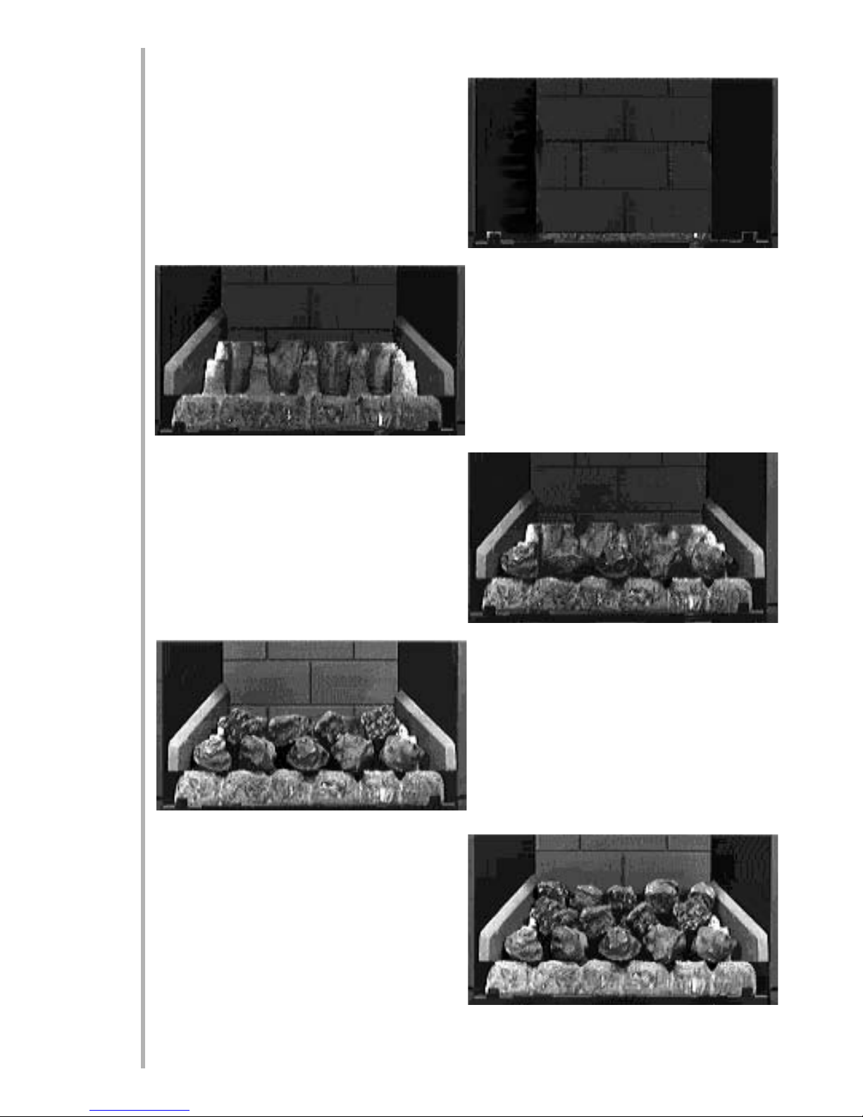
FUEL BBED LLAYOUT
Place the brick panel against the rear of the firebox.
Place the ceramic combustion matrix onto the burner and the ceramic side cheeks onto the matrix.
Ensure that the hole for pilot flame viewing is clear
and easily visible.
Place the front row of 5 moulded coals onto the
matrix, equally spaced across the width of the fire.
They may be at any rotational orientation desired.
Ensure their rear edges do not overhang the flame
ports. Corners or rough edges MUST NOT be allowed
to enter the flame ports.
Place the centre row of four broken coals, making
sure that they do not fall down into the flame port
but bridge across the spaces as shown. Rotational
orientation maybe as desired.
Place the top row of five broken coals onto the flats in
the matrix. Ensure the coals are not put into holes in
the matrix. Bridge the gaps between the support pillars and rear of the matrix and the centre row of coals.
Rotational orientation may be as desired.
5
8.0
Page 8
FUEL BBED LLAYOUT ((continued)
Note: TThe ccoalss mmusst nnot bbe ccrammed ttoggether oor iinsserted iinto tthe hholess iin tthe mmatrix. AA wwell llaid oout, ggener-
oussly sspacced ccoal llayout wwill ggive tthe bbesst rressultss.
The edges or corners of the front row of coals MUST NOT be allowed to enter the flame slots in the matrix. If
in doubt, pull them forward as far as possible.
Refit the glass door and secure in position using the four large retaining screws. Refit the front casting, and
replace the lid of the stove.
SPECIAAL NNOTE: EEvaluate tthe fflame ppiccture wwith tthe gglassss ddoor iin pplacce, ppayingg pparticcular aattention tto aany
flamess tthat pplay oonto tthe ffirebox ssidess oor fforwardss ttoward tthe gglassss ddoor. IIf tthiss iiss tthe ccasse, tturn tthe ccontrol
knob tto tthe OOFF ppossition aand aallow tthe sstove tto ccool. RRemove tthe gglassss ddoor, aand aadjusst tthe ccoalss aaccccordingg-
ly. TThiss wwill rreducce tthe ppossssibility oof hheat ddissccolouration. BBe ccareful nnot tto hhandle tthe ccoalss wwith bbare hhandss aass
they qquicckly aabssorb hheat. IIt iiss aalwayss bbesst tto sspend aa llittle eextra ttime aat tthiss ppoint tto gget tthe fflame ppiccture rrigght
than tto hhave qqueriess ffrom aa ccusstomer aat aa llater ddate. TThe mmain ffacctor aaffecctingg fflame ppiccture aand bbalancce iiss
ccoal llayout.
TESTING AAND CCOMMISSIONING
As previously mentioned, firstly turn on and test the gas supply up to the stove for any leaks, in accordance
with current Approved Codes of Practice (ACOPs).
OPERATING TTHE AAPPLIANCE
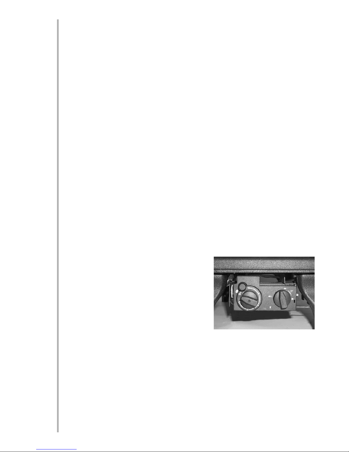
The pilot is visible through the specially added hole in the left hand side of the matrix.
Turn the thermostat knob to position 6.
Turn control knob slightly left towards the ignition position until reaching the stop, press down and hold for 5
seconds (only pilot gas is flowing). Continue pressing down the knob while turning further to the left to activate the piezo spark, continue to hold the knob down for a further 10 seconds after the pilot has been lit. If
the pilot does not light repeat the previous steps.
Upon lighting and after the further 10 seconds, release the knob and turn further to the left to the ON position. The main burner will light and be controlled in accordance
with the thermostat knob setting. Adjust the thermostat knob to
the desired setting, the higher the number the higher the room
temperature will become prior to the stove reducing its heat
input. The thermostat knob does not permanently turn the stove
on or off.
At any of the temperature settings the stove may operate at any
input between maximum and minimum or if the room temperature continues to rise, the main burner may switch off. As the
room temperature falls the main burner will light again.
If the pilot is extinguished during use of the stove, you MUST wait
ten minutes before repeating the ignition procedure. To turn the
main burner OFF, keeping the pilot flame lit, turn the control knob to the pilot position, only the pilot will
remain lit. To shut the stove off completely, press the knob down and continue turning to the right from the
pilot position to the OFF position.
A safety interlock prevents re-ignition of the pilot flame until the thermocouple has cooled sufficiently to allow
the magnetic valve unit to reset it self. The elapse time will vary dependant on the temperature of the stove.
SPARK FFAILURE
The gap between the spark electrode and the pilot should be 3 - 5mm to produce a good spark. There should
be no need to adjust this. If under any circumstances the piezo electric spark fails, the pilot cannot be lit man-
ually.
6
8.0
9.0
9.1
9.2
Page 9
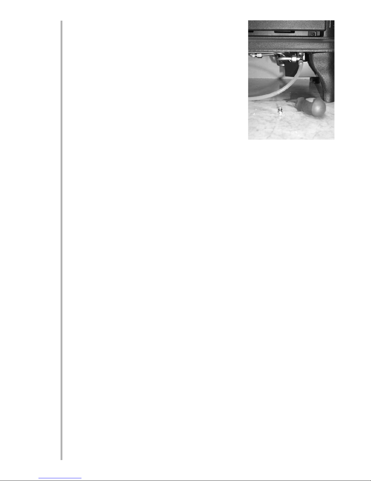
SETTING PPRESSURE
Remove the screw from the pressure test point, situated on the main burner supply pipe and protruding from between the gas valve and the fire
tray, and attach a U gauge. Light the stove and set the thermostat to the
maximum setting (6).
The burner pressure should be in accordance with the figures stated in the
data section of these instructions. The stove is factory set to achieve these
pressures and any significant variation could indicate a supply problem. If
the pressure is too high, the gas supply meter may be set incorrectly. This
should be checked with the stove running and if necessary reset by the
gas supplier.
If the burner pressure is too low, then check the meter governor pressure
with the appliance running. If this is less than approximately 20mbar it will
need to be reset by the gas supplier.
If the setting pressure is too low, but the meter pressure is acceptable, then a problem in the supply pipework
is to be suspected. This will be dirt and debris, kinked or inadequate size pipes, restriction in a fitting, shut off
elbow not fully open or solder flashing across a joint.
Switch the stove off, disconnect the U gauge and refit the test nipple screw. Light the stove and check for gas
soundness.
BRIEFING TTHE CCUSTOMER
All instructions must be handed to the user for safekeeping. Show the customer how to light and control the
stove.
After commissioning the appliance, the customer should be instructed on the safe use of the appliance and
the need for regular servicing. Frequency of service depends on usage, but MUST be carried out at least once
annually.
Advise that cleaning of the stove maybe achieved when the stove is cold using a damp cloth and mild detergent on most surfaces.
Advise that the stove will emit a "newness" smell for a time after initial commissioning and that extra ventilation may be needed during this time.
Recommend that a guard be used for the protection of the young, pets, the elderly and the infirm
SERVICING
Isolate the stove from the gas supply. Ensure that the stove is fully cold before attempting service. A suggested procedure for servicing is detailed below.
1. Lay out a dust sheet and relevant tools.
2. Removed the stove top with a sharp lift upward, then remove the stove front by lifting away.
3. Remove the glass door assembly (4 screws) and clean carefully.
4. Carefully remove the ceramic components.
5. Inspect the catalyst and clean if necessary with a soft brush.
6. Disconnect the gas supply and remove the two securing screws in the tray legs.
7. Lift away burner tray assembly.
8. Strip off the burner pipes and clean thoroughly.
9. Clean the injector, pilot assembly and the burner tube. Do not attempt to remove the pilot injector
as this can cause damage.
10. Re-assemble and re-fit the burner tray.
11. Turn on the gas supply and leak test. Check pilot and burner for good ignition.
12. Refit the ceramics, paying attention to the final layout as per installation section.
13. Refit the glass door assembly, ensuring a good seal.
77
9.3
10.0
11.0
Page 10

SERVICING ((continued)
14. Refit the cast front and then replace the lid, push firmly downward.
15. Check the purpose provided ventilation is un-obstructed.
16. Light the stove and test setting pressures.
17. Check safe operation of the appliance.
For specific servicing instructions, see relevant sections.
CLEANING TTHE CCOALS
Remove the stove top with a sharp lift upward and then the stove front by lifting away. Remove the glass door
assembly. Remove the ceramic components. Gently clean in the open air. Be careful not to create dust from
the coals. Where necessary replace damaged components with genuine spares. Seal scrap ceramic components in plastic bags and dispose at proper refuse sites as directed. If using a vacuum cleaner, a HEPA filtering
system is recommended.
Re-fit the coals by referring to the relevant section of these instructions. Refit the glass door assembly ensuring
a good seal. Refit the stove front and top.
SERVICING TTHE BBURNER TTRAY AAND GGAS AASSEMBLY
Firstly, remove the top of the stove with a sharp pull upward and then remove the front of the stove by lifting
away. remove the glass panel, coals and ceramics, and disconnect the gas connection underneath the burner.
Remove the burner tray itself by removing the 2 securing screws through the legs. The gas connections to the
gas valve can now be released. Remove the pilot and main burner pipes and blow through to dislodge any
debris. Remove the injector elbow and blow through to make sure it is entirely clear.
When replacing the injector elbow, ensure that it is aligned accurately with the centre of the mixer tube entering the burner and not at an angle. Always make sure that the nut securing the injector elbow is tight. Un-clip
the pilot lint gauze and clean with a soft brush. Clean the exterior of the pilot assembly with a soft brush and
blow through the flame ports on the pilot head. Check the aeration holes are free from lint or dirt. The pilot
assembly can be removed if required by disconnecting the electrode HT lead, gas pipe and unscrewing the
mounting screws and lifting away.
The pilot assembly is a non-serviceable item and should not be taken apart. Aeration holes must be absolutely
clear internally for proper operation.
NEVER MMODIFY OOR BBEND TTHE TTHERMOCOUPLE TTO MMAAKE TTHE
PILOT SSTAAY AALIGHT
. If the pilot will not stay lit there is a problem with dirt, the gas supply to it, the flue connection or termination, or the thermocouple needs replacement. Modifications are dangerous and can have a
serious unseen effect on safety.
The gas valve is a non-serviceable item. If this needs replacement, remove the two M5 securing screws and
remove the complete valve. Replacement must be done using original manufacturers parts.
Re-assembly in the reverse of removal.
PILOT AASSEMBLY
Remove the burner tray as in relevant section and pilot unit as described.
Clean the pilot assembly with a soft brush and blow through. Check the aeration holes are free of any dirt or
lint. Clean thoroughly internally, the connection can be removed from the base of the pilot unit using two
spanners to make cleaning easier. Do not damage or try to remove the pilot injector.
The unit is factory set and the only check necessary is to ensure the spark gap is correct. See specifications
for gas setting.
NEVER MMODIFY OOR BBEND TTHE TTHERMOCOUPLE TTO MMAAKE TTHE PPILOT SSTAAY AALIGHT
. If the pilot will not
stay lit there is a problem with dirt, the gas supply, flue termination or connection, or the thermocouple needs
replacement. Modifications are dangerous and can have a serious unseen effect on safety and therefore
MUST not be done. Replacement must be done using original manufacturers parts.
8
11.0
11.2
11.3
11.1
Page 11

CATALYST
It is recommended that the catalyst is inspected for signs of damage and dirt during routine servicing procedures.
The expected life of the catalyst is in excess of 11,000 hours (10 years of normal use). After this time the catalyst should be replaced.
If there are any deposits of dirt or soot on the catalyst they should be cleaned with a soft brush and a vacuum
cleaner. If removed for cleaning, ensure the seals are in good condition before replacing the catalyst. New
seals will usually be required.
If replacing, firstly, remove the top of the stove with a sharp pull upward. Remove the front panel of the stove
by lifting away, then remove the glass door. The catalyst is located behind the top front panel (2 screws),
remove these screws and the panel. Withdraw the catalyst and its seals forwards and discard.
Refit a new catalyst and seals in reverse order, ensure the door has a good seal.
TESTING FFOR FFIREBOX LLEAKAGE
Appliances that are several years old or have been extensively dismantled should be checked for soundness. It
is important that all the products of combustion pass through the catalytic converter at the top of the firebox
before leaving the appliance.
The firebox is heated by lighting for a few minutes to provide a flow through the firebox and flue. The burner
is then shut off and a smoke pellet or match introduced at the base of the stove underneath the burner tray.
Large quantities of smoke will emerge from the top of the appliance, but none should emerge from the joints
or gasket faces, especially around the door. It is important to note that the appliance can never be expected to
be 100% smoke tight and small quantities of smoke may be seen in corners of joints and gasket faces etc without affecting safety when the stove is actually in operation.
9
11.4
11.5
Page 12

TROUBLESHOOTING GGUIDE
Stove ssparkss bbut ppilot ddoess nnot lligght
No gas to stove, check isolators are open.
Pipe work blockage, clean out.
Air not fully purged, re purge supply or wait longer.
Spark earthing to metal work, reset gap correctly.
Blocked pilot, clean out internally.
Pilot lligghtss bbut tthen ggoess oout
Severe restriction in gas supply: clear obstruction.
Faulty thermocouple, replace pilot unit.
Blocked pilot, clean out.
Blocked lint gauze, clean.
Hold control knob in for longer.
NEVER MODIFY OR BEND THE THERMOCOUPLE TO MAKE THE
PILOT STAY ALIGHT. If the pilot will not stay lit there is a problem
with dirt, the gas supply, or the thermocouple needs replacement.
Modifications are dangerous and can have a serious unseen effect
on safety.
Remote hhandsset ddoess nnot ooperate tthe
Replace the batteries in the battery box/receiver underneath the
temperature ccontrol
stove.
Stove ddoess nnot sspark aat ppilot
HT lead detached, refit.
Spark gap too large or small, reset correctly.
Faulty piezo unit, replace.
Debris shorting out electrode, clean.
Spark shorting to metalwork under tray, realign HT lead.
Stove rrunss ffor aa ttime aand tthen ccutss ooff
Loose or faulty thermocouple, rectify.
Blocked pilot, clean out.
Dirt or lint in pilot aeration hole or on the lint gauze, clean
thoroughly.
NEVER MODIFY OR BEND THE THERMOCOUPLE TO MAKE THE
PILOT STAY ALIGHT. If the pilot will not stay lit there is a problem
with dirt, the gas supply, flue termination or connection, or the
thermocouple needs replacement. Modifications are dangerous
and can have a serious unseen effect on safety.
Pilot fflame sshrinkss wwhen sstove iiss oon hhiggh
Poor gas flow to stove, check pressure with stove on high.
If pressure is low, remove any restriction in pipework or valve.
Check all isolators are adequately sized and fully open.
Check meter pressure is adequate.
NEVER MODIFY OR BEND THE THERMOCOUPLE TO MAKE THE
PILOT STAY ALIGHT. If the pilot will not stay lit there is a problem
with dirt, the gas supply, flue termination or connection, or the
thermocouple needs replacement. Modifications are dangerous
and can have a serious unseen effect on safety.
Stove ssmellss wwhen ffirsst llit oor iin uusse
Newness smell from brand new appliance.
Leakage occurring. Carry out leakage test and rectify any problems.
Low temperature sealants or combustible materials used in
incorrect positions.
10
12.0
Page 13

USER IINSTRUCTIONS
Secction Content Pagge NNo
1.0 Important Notes 1
2.0 Clearances to Combustibles 2
3.0 Ventilation & Room Size 2
4.0 Operating Instructions 2
5.0 Combustion Spillage Monitoring System 3
6.0 Cleaning 3
6.1 Coals & Ceramics 3
7.0 Servicing 5
8.0 List of Replacement Parts 5
IMPORTANT NNOTES
The installation and Servicing of this stove MUST only be carried out by a competent person (such as a
CORGI registered fitter) in accordance with the Gas Safety (Installation and Use) Regulations 1998, the relevant British Standards, Codes of Practice, the Building Regulations and the manufacturer's instructions.
Failure to comply with the above recommendations could lead to prosecution and will invalidate the appliance warranty.
Please ensure you are handed all of the manufacturers documents on completion of the installation. This will
include these instructions.
Always keep a note of the installer's name and address, the original purchase receipt and the date of installation for future reference. Failure to produce these documents may invalidate the warranty.
The stove should be serviced regularly to ensure continued safe operation. See the servicing section for further reference.
Parts of this appliance become naturally hot during use. It is recommended that a suitable fireguard conforming to BS 6778 or BS 6539 is used, especially where young children, pets, the elderly or infirm are concerned.
The stove is fitted with a removable handle which can get hot if it is not removed from the door whilst the
stove is in operation .
This stove is designed to become very hot during use. The manufacturer of this appliance considers all surfaces as working surfaces with the exception of the control knob and control panel.
Combustible items, such as flooring and furniture and soft wall coverings (such as blown vinyl or embossed
paper), low temperature surrounds etc may discolour if fitted too close to the stove. See relevant section for
further details on clearances to combustibles. No combustible materials or flooring should protrude onto the
hearth.
This appliance incorporates a combustion monitoring system (ODS)
DO NOT burn any foreign material on this stove, the coals must be of the correct type and laid out in accordance with the relevant section of the these instructions. Failure to do so may create a hazard or lead to sooting. Under no circumstances shall the appliance be used if the glass front door or panel has been removed,
damaged or is open.
Do not place any objects on top of the stove.
The integral catalyst should be checked by the installer upon servicing to ensure there are no defects or
obstructions that may prevent the satisfactory flow of combustion products.
The expected life of the catalyst is in excess of 11,000 hours (10 years of normal use). After this time the catalyst should be replaced.
11
1.0
Page 14
This appliance is only suitable for the gas type for which it is supplied.
CLEARANCES TTO CCOMBUSTIBLES
Clearance to the sides of the stove are 100mm (4in) but curtains, drapes and other fabrics are not permitted
within a distance of 500mm (20in) of the stove sides and back. No such materials are permitted directly
above the stove regardless of distance. Clearance to the front of the stove is 1000mm (39”). Clearance to the
rear of the stove is 100mm (4”).
It is not permitted to install the appliance onto carpet, rugs or fabric materials of any kind.
A combustible shelf may be fixed to the wall above the stove, providing that it complies with the dimensions
given below.
The shelf depth may be greater but the height must also be increased accordingly. An increase in height of 25
mm is required for every 12.5 mm of additional shelf depth. For shelves that are too low, protective devices
can be used such as metal heat deflectors, but it must be assured that the shelf does not reach an unacceptable temperature before relying on such a solution.
As with all heating appliances, any decorations, soft furnishings, and all coverings (i.e. flock, blown vinyl and
embossed paper) positioned too close to the appliance may discolour or scorch.
VENTILATION AAND RROOM SSIZE
Purpose provided ventilation of 100cm2 is required for this appliance. An openable window or equivalent is
also required.
Any ventilation fitted must comply with BS 5871 part 2 and BS 5440 part 2. Ventilation fitted under, or within
immediate vicinity of the appliance must not be used as it may adversely effect performance of the combustion monitoring system (ODS) system.
The requirements of other appliances operating in the space or room must be taken into consideration when
assessing ventilation requirements, this will have been carried out by your CORGI registered installer.
A supply of fresh air into the room is advisable to maintain temperatures within limits.
The appliance MUST NOT be installed in a bedroom, bathroom or any sleeping area.
For Republic of Ireland, see relevant rules in force.
The room size should be a minimum of 40m3 to allow adequate
circulation of air and ensure the correct operation of the stove.
OPERATING IINSTRUCTIONS
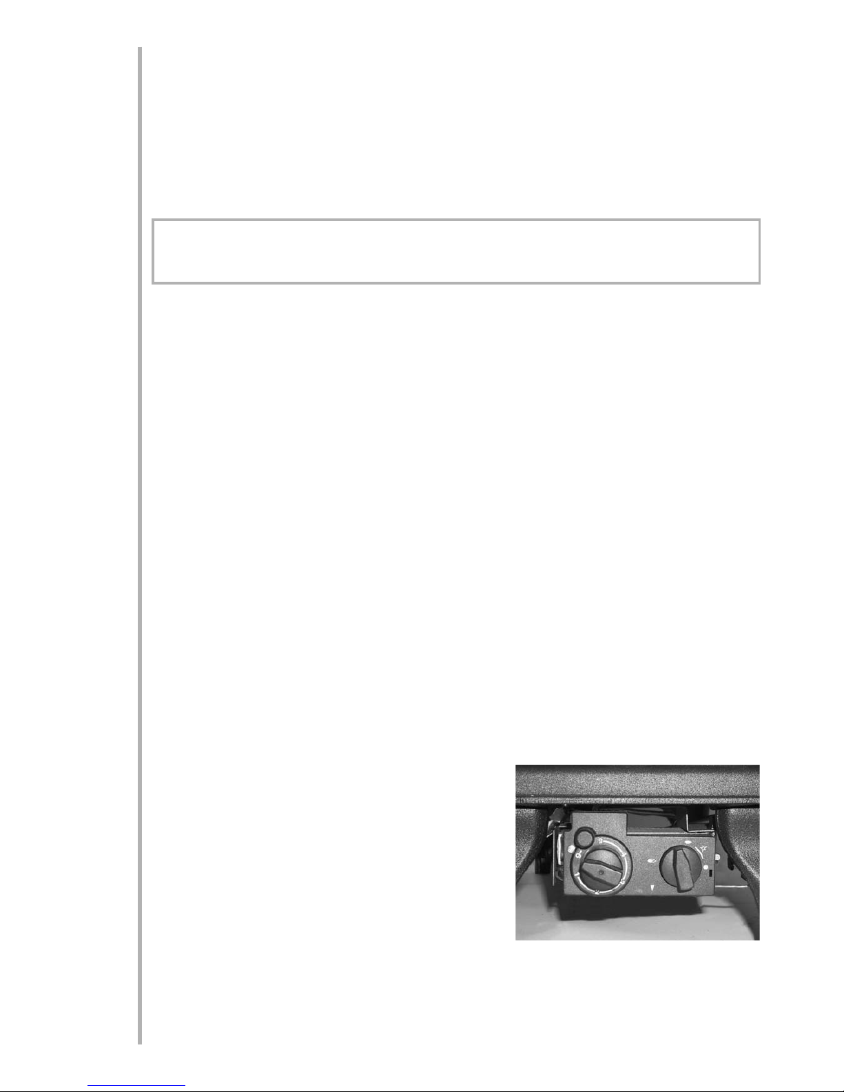
The pilot is visible through the small hole in the left hand side of
the matrix front edge.
Turn the thermostat knob to position 6
Turn control knob slightly left towards the ignition position until
reaching the stop, press down and hold for 5 seconds (only pilot
gas is flowing)
Continue pressing down the knob while turning further to the left to activate the piezo spark, continue to hold
the knob down for a further 10 seconds after the pilot has been lit. If the pilot does not light repeat the previous steps.
12
2.0
3.0
4.0
Maximum ddepth oof sshelf Minimum ddistancce ffrom hhearth tto uunderside oof sshelf
150mm (6in) 1015mm (40in)
200mm (8in) 1115mm (44in)
Page 15
Upon lighting and after the further 10 seconds, release the knob and turn further to the left to the ON position. The main burner will light and be controlled in accordance with the thermostat knob setting. Adjust the
thermostat knob to the desired setting, the higher the number the higher the room temperature will become
prior to the stove reducing its heat input.
OPERATING IINSTRUCTIONS ((continued)
At any of the temperature settings the stove may operate at any input between maximum and minimum or if
the room temperature continues to rise, the main burner may switch off. As the room temperature falls the
main burner will light again.
If the pilot is extinguished during use of the stove, you MUST wait ten minutes before repeating the ignition
procedure. To turn the main burner OFF, keeping the pilot flame lit, turn the control knob to the pilot position,
only the pilot will remain lit. To shut the stove off completely, press the knob down and continue turning to
the right from the pilot position to the OFF position.
A safety interlock prevents re-ignition of the pilot flame until the thermocouple has cooled sufficiently to allow
the magnetic valve unit to reset it self. The elapse time will vary dependant on the temperature of the stove.
COMBUSTION MMONITORING SSYSTEM
This stove is fitted with a combustion monitoring safety device (ODS). If the stove shuts down during use for
no apparent reason then several reasons may be suspected. If a door or window has been opened creating a
draught, then pilot disturbance could be the problem and removal of the draught should resolve this. The
stove can then be re-lit in accordance with the previous section.
If pilot disturbance is not the cause, then the ODS safety system may be in operation. Switch the appliance
OFF, call in your installer to check the appliance and ventilation. Remedial work must be carried out as
required. DO NOT allow the appliance to be used until the appliance and installation is passed as safe. If the
pilot continues to be extinguished, you must call your installer to check the operation of the complete appliance.
CLEANING
Before carrying out any of the following operations, ensure that the stove is OFF and completely cold. Debris
that may form on the fire bed should be periodically removed by a competent person. Large deposits could
indicate flue problems or incorrect coal placement. This should be repaired by a competent person and the
stove serviced before further use. To gain access to the fire bed, lift off the lid of the stove, and then lift out
the front casting. Remove the four retaining screws and detach the glass door assembly. The glass can be
cleaned with a suitable glass cleaner. Test on a small area first.
Always ensure the area below the stove is clear of any debris or dust.
PAINTED AREAS - These can be cleaned using a dry cloth.
COALS AAND CCERAMICS
Lift off the lid of the stove and lift out the front casting. Remove the glass door assembly. Remove the
ceramic components. Gently clean in the open air.
Be careful not to create dust from the coals. Where
necessary replace damaged components with genuine spares. Seal scrap ceramic components in plastic bags and dispose at proper refuse sites as directed. If using a vacuum cleaner, a HEPA filtering system
is recommended.
Replacing the coals and ceramics are as follows
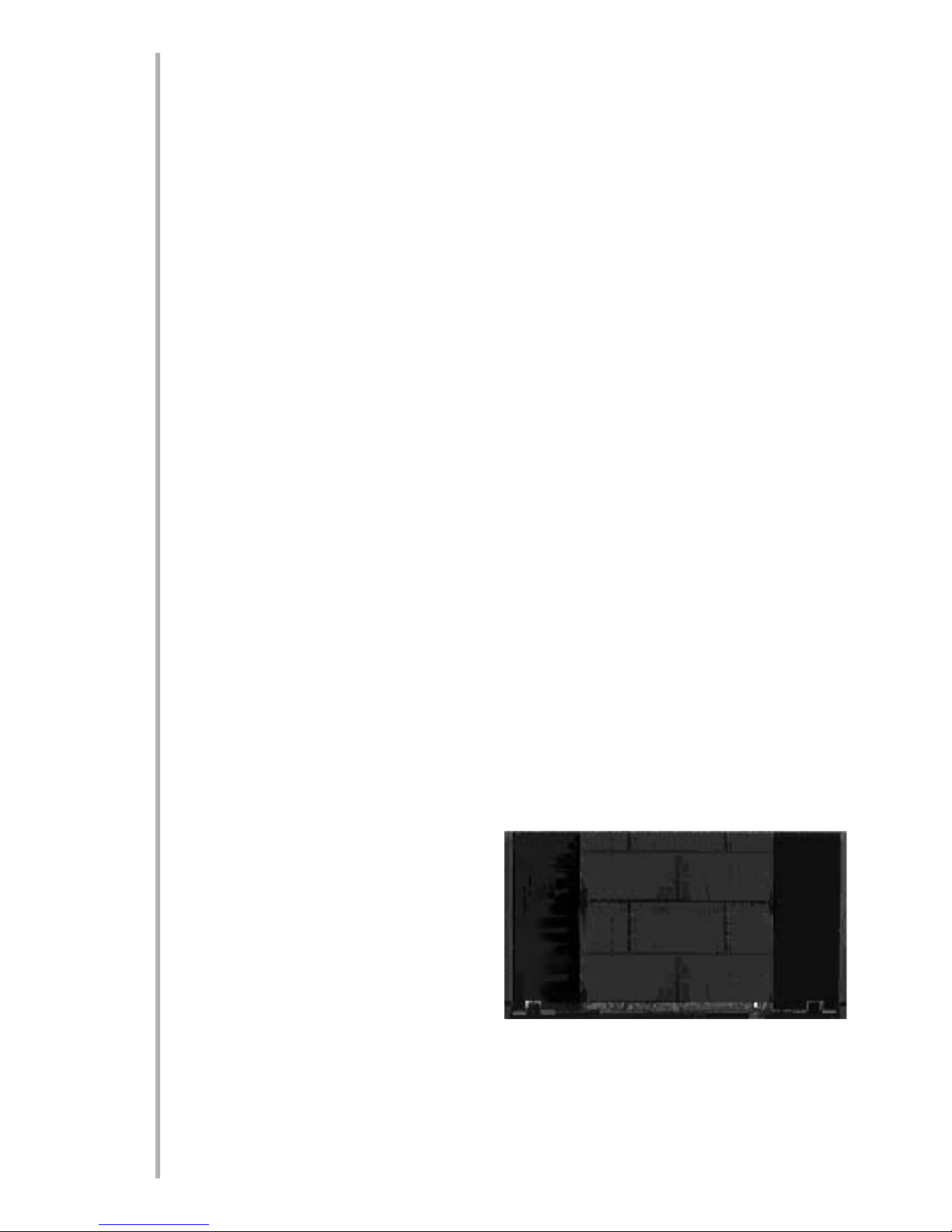
Place the brick panel against the rear of the firebox.
13
4.0
5.0
6.0
6.1
Page 16
COAL AND CERAMICS ((contin-
ued)
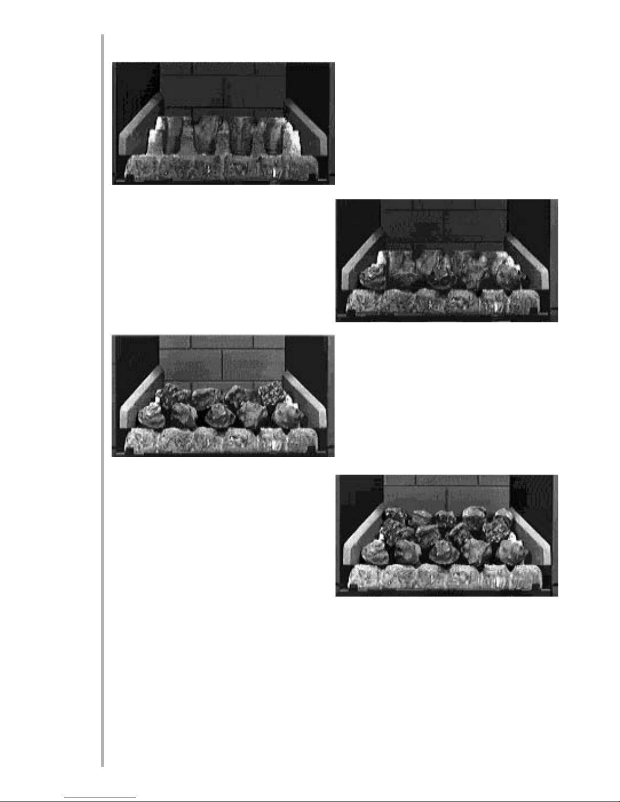
Place the ceramic combustion matrix onto the burner
and the ceramic side cheeks onto the matrix. Ensure
that the hole for pilot flame viewing is clear and easily
visible.
Place the front row of 5 moulded coals onto the
matrix, equally spaced across the width of the fire.
They may be at any rotational orientation desired.
Ensure their rear edges do not overhang the flame
ports. Corners or rough edges MUST NOT be
allowed to enter the flame ports.
Place the centre row of four broken coals, making sure
that they do not fall down into the flame port but
bridge across the spaces as shown. Rotational orientation maybe as desired.
Place the top row of five broken coals onto the flats in the matrix. Ensure the coals are not put into holes in
the matrix. Bridge the gaps between the support pillars and rear of the matrix and the centre row of coals.
Rotational orientation may be as desired.
Note: TThe ccoalss mmusst nnot bbe ccrammed ttoggether oor iinsserted iinto tthe hholess iin tthe mmatrix. AA wwell llaid oout, ggener-
oussly sspacced ccoal llayout wwill ggive tthe bbesst rressultss.
The edges or corners of the front row of coals MUST NOT be allowed to enter the flame slots in the matrix. If
in doubt, pull them forward as far as possible.
14
6.1
Page 17

Refit the glass door and secure in position using the four large retaining screws. Refit the front casting, and
replace the lid of the stove.
COAL AAND CERAMICS (continued)
SPECIAAL NNOTE: EEvaluate tthe fflame ppiccture wwith tthe gglassss ddoor iin pplacce, ppayingg pparticcular aattention tto aany
flamess tthat pplay oonto tthe ffirebox ssidess oor fforwardss ttoward tthe gglassss ddoor. IIf tthiss iiss tthe ccasse, tturn tthe ccontrol
knob tto tthe OOFF ppossition aand aallow tthe sstove tto ccool. RRemove tthe gglassss ddoor, aand aadjusst tthe ccoalss aaccccordingg-
ly. TThiss wwill rreducce tthe ppossssibility oof hheat ddissccolouration. BBe ccareful nnot tto hhandle tthe ccoalss wwith bbare hhandss aass
they qquicckly aabssorb hheat. IIt iiss aalwayss bbesst tto sspend aa llittle eextra ttime aat tthiss ppoint tto gget tthe fflame ppiccture rrigght
than tto hhave qqueriess ffrom aa ccusstomer aat aa llater ddate. TThe mmain ffacctor aaffecctingg fflame ppiccture aand bbalancce iiss
ccoal llayout.
SERVICING
The stove should be checked on an annual basis to it is working safely and that there is no excessive build up
of soot. The frequency of service will depend on usage, but MUST be carried out at least once annually.
Servicing must be carried out by a competent person, such as a CORGI registered installer.
Cleaning of the coals may be carried out by following the instructions given in the Installation section. The
Installation instructions carry full servicing details for the use of the installer.
LIST OOF SSPARE PPARTS
PAART NNO. ITEM
FT003820-0 Pack of 5 moulded coals
FT003825-0 Pack of 9 broken coals
FT003815-0 Ceramic combustion matrix
FB004030/0 Ceramic side cheeks
FB004050/0 Ceramic brick panel
FB004225/5 Glass door assembly
FT003710/5 Pilot assembly
Please Enquire Gas valve
Please Enquire Burner tray
Please Enquire Catalyst (seal kit must also be supplied)
Please Enquire Seal kit for Catalyst
15
8.0
7.0
6.1
 Loading...