

Page 1

FDP 1.2000 : ONE CHANNEL AMPLIFIER
Operation / Configuration
POWER PER CHANNEL
• 1 x 1200 wRMS @ 4ohms
• 1 x 2000 wRMS @ 2ohms
• 1 x 4000 wRMS (Two FDP 1.2000s Bridged @ 4 ohms)
• 1 x 2400 wRMS (Two FDP 1.2000s Bridged @ 8 ohms)
• Note: FDP 1.2000 is not 1 ohm stable, and cannot be bridged at 2 ohms
INPUT/OUTPUT CONFIGURATIONS
Because this is a one channel amplifier, if both left and right inputs are used, they are mixed to mono, which is useful
for subwoofers.
CROSSOVER CONFIGURATION
The 48 dB per octave HP and 24 dB per octave LP filters are always on so that they function as a Band Pass for a
subwoofer, or a midbass in a 3-way speaker. If you use a DSP or external crossover, set HP to 8Hz and LP to 350 Hz.
• HP frequency adjustment range is 8 Hz to 53 Hz, can use as a subsonic filter or crossover.
LP frequency adjustment range is 40 Hz to 350 Hz.
• The remote level control is always active.
There is a PWR-PEAK light on the remote level control.
If the light is red or flashing red, reduce volume until the light turns green so that you do not damage your
speaker.
• PHASE is continuously adjustable between 0 degrees and 180 degrees. Adjust by measuring frequency response
at the crossover frequency. Frequency response should be as smooth as possible.
SUBHARMONIC SYNTHESIZER - SHS
• SHS will add deeper bass to music that lacks it. Music is sampled and new tones one octave lower are
synthesized. The levels at 45Hz and 30Hz are set on the amplifier to music taste.
• The remote must be plugged in for SHS to function. The SHS knob on the remote will adjust the amount of
synthesized level mixed with the music.
• Avoid excess SHS level because this will make the subwoofer sound “muddy” and cause the amplifier to have
distortion prematurely.
• There is a switch on the amplifier to turn SHS off.
AUTOMATIC POWER TURN ON/OFF
1. The best way to automatically turn the amplifier power on and off is to use the REM wire from your source radio
connected to the REM amplifier terminal.
2. If your original equipment stereo or source radio has a BTL amplifier, then the RCA inputs have an auto turn on
sensing circuit. When connecting high level BTL speaker wires to the RCA input, the REM wire is not necessary.
RCA INPUT, BOTH LOW LEVEL AND HIGH LEVEL
The amplifier
jacks. A factory source radio that does not have RCA output, using the wires that are connected to the speakers, can be
directly connected to the RCA jacks when the amplifier LEVEL control is adjusted to 8V.
LEVEL control has sufficient adjustment range for both low level and high level input into the RCA
1
Page 2

SETTING LEVEL
• Set the amplifier
• For lowest distortion and lowest noise the amplifier LEVEL should be set at the lowest setting that yields
sufficient loudness without distortion. For lowest noise your source radio volume control should be near
maximum that does not cause distortion.
• To find the best amplifier LEVEL setting:
With the amplifier LEVEL at minimum, slowly increase the source radio volume to around 3/4 without distortion.
Then, slowly turn up the amplifier LEVEL control to the maximum desired loudness. Listen very carefully and
turn down the amplifier LEVEL control if you hear any distortion.
LEVEL control to minimum before you turn on the amplifier for the first time.
SUBWOOFER REMOTE VOLUME CONTROL LED LIGHT
1. While playing music the LED light should be Green.
Occasional red LED light flash indicates that the amplifier has reached maximum loudness.
2. If the red LED light flashes with the beat of the music,
TURN DOWN THE VOLUME before you damage your speaker.
3. If the red LED light is on continuous,
TURN DOWN THE VOLUME before you damage your speaker.
SETTING SUBWOOFER HIGH PASS SUBSONIC FILTER
• A subwoofer should have a high pass filter often called a subsonic filter. The purpose of a subsonic filter is to
limit very low frequencies that your subwoofer can not play loud enough without damage. Removing subsonic
frequencies can allow your subwoofer to play louder.
• For a sealed box the high pass is typically set between 8 Hz and 30 Hz to increase power handling capacity.
• For a vented box the high pass filter must be set 5 Hz lower than the port tune frequency to prevent woofer damage.
DIRECT / MASTER SWITCH
• For normal operation set the switch to “MASTER”.
• The DIRECT switch position bypass the crossover functions, subharmonic synthesizer, level control and remote
controls. DIRECT mode can be used with an external DSP controlling all functions and level or if the amplifier
is controlled by a second amplifier. DIRECT is also used if two amplifiers are connected in bridge or parallel
cascade.
UNBAL / BAL SWITCH
The standard switch position is input “UNBAL”. Flipping the switch to “BAL” will change the input to“balanced input
floating ground” and may reduce vehicle electronics noise.
DIAGNOTIC AND PROTECTION LED PANEL
• Peak Output: Red LED light flash indicates that the amplifier has reached maximum loudness.
• DC Protect: Output fault- the amplifier must be returned for service.
• 158 F: Maximum temperature before thermal protection, you need better cool air venteliation.
• 135 F: Safe operating temperature.
Over Current: Speaker impedance is too low OR there is a short circuit.
•
• Over Voltage: DC power voltage is too high, some vehicles have a fast battery charge mode that trigger this. -
• Fuse: The power fuse is blown and must be replaced.
• Fuse: The power fuse is blown and must be replaced.
2
Page 3
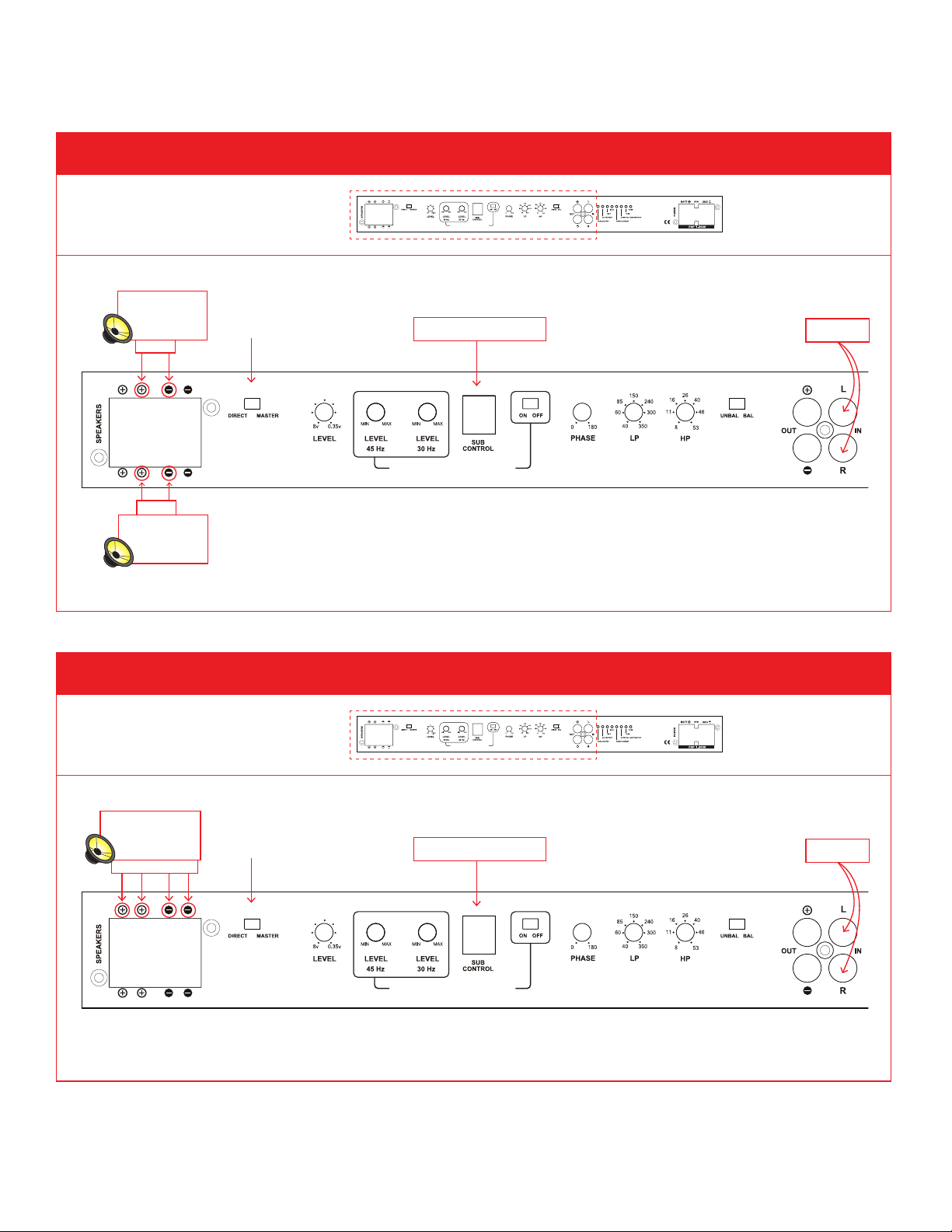
ONE AMPLIFIER IN HP, LP OR BP MODE (SEE GRAPHICS A1 + A2)
A1: ONE AMPLIFIER AND SINGLE VOICE COIL WOOFER
(Diagram below only shows
SINGLE
VOICE COIL
SUBWOOFER
+–
+–
SINGLE
VOICE COIL
SUBWOOFER
this portion of the amplifier)
MASTER
SUBHARMONIC SYNTHESIZER
NOTE: If 2 or more subwoofers are used, parallel minimum impedance is 2 ohms.
SUBHARMONIC SYNTHESIZER
REMOTE SUB CONTROL
RADIO
A2: ONE AMPLIFIER AND DUAL VOICE COIL WOOFER
(Diagram below only shows
DUAL
VOICE COIL
SUBWOOFER
++––
this portion of the amplifier)
MASTER
SUBHARMONIC SYNTHESIZER
NOTE: With voice coils in parallel, minimum impedance is 2 ohms.
SUBHARMONIC SYNTHESIZER
REMOTE SUB CONTROL
RADIO
3
Page 4

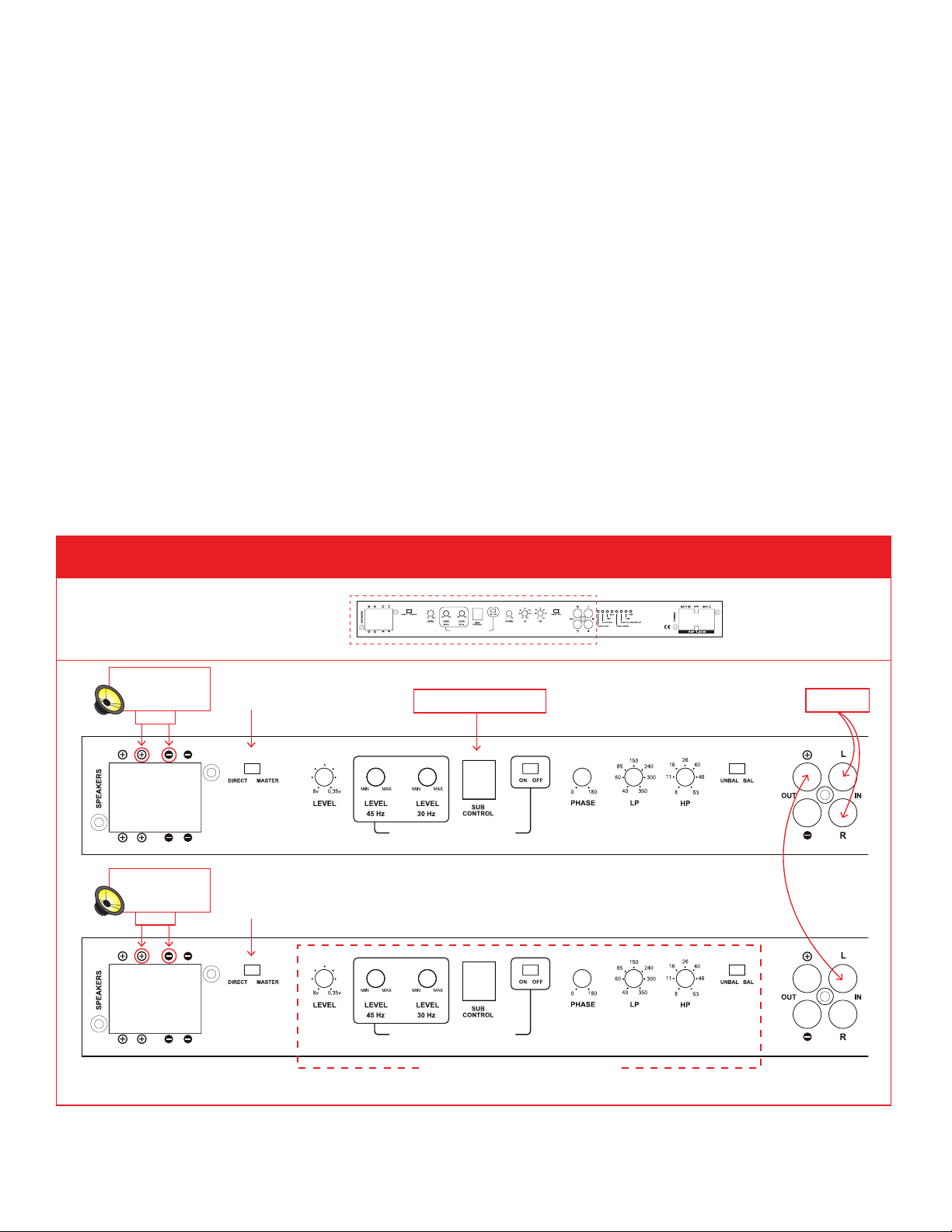
TWO AMPLIFIERS IN BRIDGED MODE (SEE GRAPHIC A3)
• TWO FDP 1.2000 amplifiers are required.
• Amplifier #1 will have
MASTER switch selected.
Amplifier #2 will have DIRECT switch selected.
• Crossover and level controls will only function on MASTER amplifier #1.
• By selecting DIRECT on amplifier #2 all crossover and level controls are bypassed and the LEFT input channel
must be used.
• Master Amplifier #1 will receive the source signal on left and right channels.
Master Amplifier #1 RCA “out -” will connect to direct amplifier #2 RCA “L IN”.
The LEFT input channel must be used.
• The (speaker +) will connect to Amplifier #1 (+ speaker).
The (speaker -) will connect to Amplifier #2 (+ speaker).
• The (speaker -) on Amplifier #1 will connect to (speaker -) on Amplifier #2.
A3: TWO AMPLIFIERS IN BRIDGE MODE
(Diagram below only shows
this portion of the amplifier)
MASTER
SUBHARMONIC SYNTHESIZER
REMOTE SUB CONTROL
RADIO
SUBWOOFER
SUBHARMONIC SYNTHESIZER
+
–
DIRECT
SUBHARMONIC SYNTHESIZER
THESE CONTROLS ARE BYPASSED
4
Page 5
MULTIPLE AMPLIFIERS IN PARALLEL CASCADE MODE
(SEE GRAPHIC A4 FOR 2-AMP CONFIGURATION EXAMPLE; SEE GRAPHIC A5 FOR 2 OR MORE AMP CONFIGURATION EXAMPLE)
• TWO or more FDP 1.2000 amplifiers are required.
1. Use this mode when you have several speakers that will use the same crossover and loudness setting
and will have one amplifier on each speaker.
2. One example is a dual voice coil subwoofer and you use one amplifier on each voice coil. (A5)
3. A second example is you have several subwoofers and will use one amplifier on each subwoofer. (A4)
• Amplifier #1 will have
MASTER switch selected.
Amplifier #2,3,4.... will have DIRECT switch selected.
• Crossover and level controls will only function on amplifier #1.
• By selecting DIRECT on amplifier #2,3,4.... all crossover and level controls are bypassed and the LEFT input
channel must be used.
• Master Amplifier #1 will receive the source signal on left and right channel.
Master Amplifier #1 RCA “out +” will connect to direct amplifier #2,3,4.... RCA “L IN”.
The LEFT input channel must be used.
• One speaker + & - will connect to one Amplifier’s + & -.
A4: MULTIPLE AMPLIFIERS IN PARALLEL CASCADE MODE
(Diagram below only shows
SINGLE VOICE COIL
SUBWOOFER
+–
this portion of the amplifier)
MASTER
SUBHARMONIC SYNTHESIZER
REMOTE SUB CONTROL
RADIO
SINGLE VOICE COIL
SUBWOOFER
+–
SUBHARMONIC SYNTHESIZER
DIRECT
SUBHARMONIC SYNTHESIZER
THESE CONTROLS ARE BYPASSED
5
Page 6

A5: TWO AMPLIFIERS IN PARALLEL CASCADE MODE WITH DUAL VOICE COIL SUB
(Diagram below only shows
this portion of the amplifier)
SUBHARMONIC SYNTHESIZER
+
–
+
–
MASTER
DUAL VOICE COIL
SUBWOOFER
DIRECT
REMOTE SUB CONTROL
SUBHARMONIC SYNTHESIZER
SUBHARMONIC SYNTHESIZER
THESE CONTROLS ARE BYPASSED
RADIO
POWER FUSES
1.2000 POWER FUSES
Six Fuses (25 Amp ATC)
> TO USE: Remove 5 screws from bottom panel and 2 screws from side panel.
6 x 25 amp ATC fuses
6
Page 7

TROUBLESHOOTING
> FOCAL SIGN DOES NOT LIGHT
1. Measure the voltage at the amplifier power terminal. It should be between 12 and 15 volts.
2. Measure the voltage at the amplifier REM terminal. It should be between 12 and 15 volts.
3. If you are using BTL high level for automatic turn on, try connecting a REM wire.
4. Check your power and ground connections to be correct polarity (+ and -) and make sure they are tight.
5. Check battery connections.
6. Check the fuse in the REM wire.
7. Check fuse at battery.
8. Check fuse inside amplifier. (CHECK DIAGNOSTIC AND PROTECTION LED PANEL, Pg 2)
• The fuses are located inside the right end cap of the amplifier beside the power terminals. The
recommended fuse size is six 25 amp ATC.
> FOCAL SIGN LIGHT IS FLASHING
1. Is the amp very hot? (CHECK DIAGNOSTIC AND PROTECTION LED PANEL, Pg 2)
• If yes: Wait a few minutes for it to cool down. You need to get more fresh cool air to the amplifier.
Do not cover the amplifier or mount it flush into a hole.
2. Possible Short Circuit (CHECK DIAGNOSTIC AND PROTECTION LED PANEL, Pg 2)
• Check connections for small “wire whiskers” that may be shorting between amplifier terminals or speaker
terminals.
• Disconnect the speaker wires from the amplifier and turn the amplifier on. Does the light go solid?
If yes: Keeping the speaker wires disconnected from the amplifier, use an ohm meter to measure the speaker
wires for short circuit.
> NO SOUND AND THE FOCAL SIGN LIGHT IS SOLID
1. Make sure the source radio is on and that there a sound signal coming from the source radio.
2. Double check your connections to the source radio.
3. Make sure you using the correct source radio wires and that they are plugged into the correct amplifier RCA.
4. Double check your connections to the speakers and speaker crossovers.
5. Check that all amplifier switches are in the correct positions for your speaker set up.
6. Check that HP frequency is LOWER than LP frequency.
> AMPLIFIER BLOWS FUSE WHEN YOU TURN IT ON
1. Power and ground may be reversed.
Check + and - polarity at amplifier and at battery.
> SUBWOOFER REMOTE VOLUME CONTROL DOES NOT FUNCTION
1. Check that Remote Volume Control wire is plugged into the amplifier securely.
2. The Remote Volume Control will not function if the amp switch is DIRECT. The switch must be in MASTER.
> SUBHARMONIC SYNTHESIZER DOES NOT FUNCTION
1. The remote level control must be plugged in.
2. Increase the 45Hz level and the 30 Hz Level.
7
Page 8

WARRANTY INFORMATION
Focal America / Orca Design & Manufacturing supports their products and guarantees them to be free of
manufacturing defects for a period of 1 year (non-transferrable) from the date of purchase, if purchased
from and authorized retailer. This time period is extended to 3 years (non-transferrable) from the date of
purchase, if the amplifier is purchased from and installed by an authorized retailer, and no alterations are
made to the installation or setup of the amplifier outside of the authorized retailer.
This manufacturing warranty does not extend to situations involving physical or installation damage, misuse,
abuse, or modification. If an amplifier malfunctions, please return it to the authorized retailer from which the
amplifier was purchased to have the amplifier and/or installation inspected and to have the warranty period
verified from date of purchase.
The authorized dealer will then work with Focal America / Orca Design & Manufacturing to obtain service, if
necessary. If found to be a defect due to manufacturing, the item will be repaired or replaced with a refurbished
amplifier. The amplifier will be returned to the authorized retailer when repairs are complete, so that the
dealer can return the amplifier to you, or reinstall the amplifier to maintain the above mentioned warranty
timeline.
TECHNICAL SPECIFICATIONS
• 1200w x 1 into 4 ohms
• 2000w x 1 into 2 ohms
• Not 1 ohm stable
• Two amps can be bridged to 2400w x 1 into 8
ohms
• Two amps can be bridged to 4000w x 1 into 4
ohms
• No 2 ohm bridged operation allowed
• THD .09%
• S/N – 105 dB
• Sub harmonic synthesizer with two bandpass
filters (30 Hz & 45 Hz) with external control (incl.)
• Sub Sonic (High Pass) Crossover - 8 Hz to 53 Hz,
48 dB/Octave Linkwitz-Riley
• Low Pass Crossover - 40 Hz to 350 Hz, 24dB/
octave Linkwitz-Riley
• RCA input can use BTL Source or common ground
source up to 8 volts
For more information and technical specs, visit us online at: http://Focal-America.com
• RCA Line Outputs, one in phase for cascading amplifiers,
one anti phase for bridging.
• Continuous phase adjustment 0 – 180°
• Selectable Balanced/Unbalanced inputs
• Remote Control of Subwoofer Level, Subharmonic
Synthesizer Level, and Continuous phase adjustment
• Remote Control includes peak output level light
• Recommended DC Voltage operating range 11.5 to 14.4
Volts
• Maximum DC Voltage range 8 to 16 Volts
• Level control 350mV to 8v
• Twin frequency locked regulated power supplies
• Diagnostic and Protection LED panel showing Peak
Output, DC protect, 135 deg F, 158 deg F, Over Current,
Over Voltage and Fuses.
• Length 19” Width 8” Height 2”
• Weight 12 lbs
• Fuse 6 x 25 Amp ATC
8
 Loading...