

Page 1
Page 2

CONTENTS
Section
INSTALLATION 1.0 ................................................................................................. 2
Connecting the hose/dispenser assembly to the chemical cylinders 1.1.............2
Connecting the red "A" hose to the "A" chemical cylinder 1.2 ..............................2
Connecting the red "B" hose to the "B" chemical cylinder 1.2...............................4
Connecting the nitrogen hoses 1.3.................................................................................4
STARTUP | CALIBRATION 2.0................................................................................ 6
Startup 2.1 .............................................................................................................................6
Calibration of A:B ratio 2.2............................................................................................12
MAINTENANCE | SERVICE 3.0............................................................................22
Air Injection System 3.1.................................................................................................. 22
Trigger (D300) 3.1.1..........................................................................................................24
Handle (D201) 3.1.2.......................................................................................................... 24
Air Cylinder/ Piston Assembly (D300) 3.1.3............................................................... 26
Carrier Assembly (D500) 3.2.1....................................................................................... 40
Chemical Valve Service (D503R & D503B) 3.2.2...................................................... 40
Filter Screen Service (D504) 3.2.3 ................................................................................ 42
Check Valve Service 3.2.4 ............................................................................................... 44
Mix Cartridge Service (D603 or Optional Cartridge) 3.2.5.................................... 46
Mix Cartridge Removal and Cleaning (D603 or Optional Cartridge) 3.2.6....... 48
©2001 R11.01
SHUTDOWN 4.0 ................................................................................................... 52
Shutdown Procedure 4.1................................................................................................. 52
TROUBLESHOOTING 5.0 ...................................................................................... 54
PARTS LIST 6.0 .....................................................................................................55
FOAMPRO® F1000
1
Page 3

INSTALLATION
1.0
1.1
Usually the Foampro dispenser is shipped to customers with the hose assembly
already connected to the dispenser. If your Foampro dispenser is not connected to
the hose assembly:
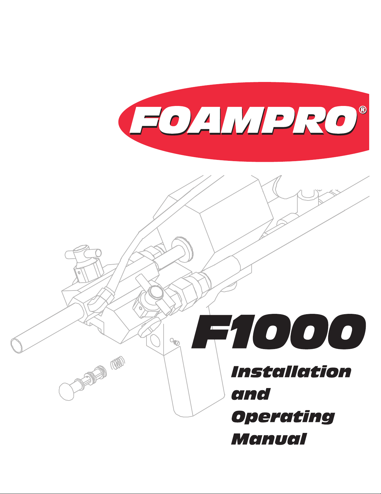
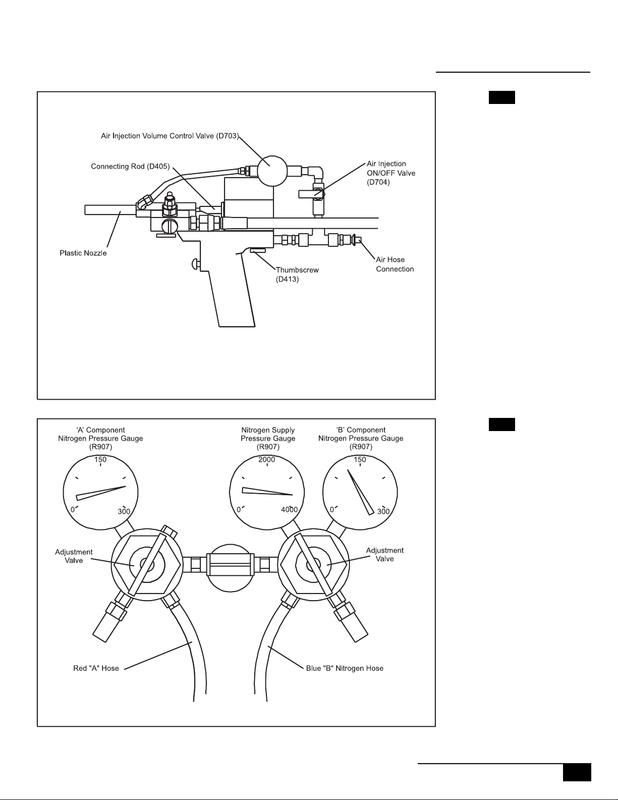
Attach the red “A” hose to the Hose Connection Fitting (D507) on the left side
of the dispenser, just behind the red valve.
Attach the blue “B” hose to the Hose Connection Fitting (D507) on the right
side of the dispenser, just behind the blue valve.
Attach the gray air pressure line to the quick connect fitting at the rear of the
dispenser.
(See diagram 3A)(See diagram 3A)
(See diagram 3A)
(See diagram 3A)(See diagram 3A)
(See diagram 3A)(See diagram 3A)
(See diagram 3A)
(See diagram 3A)(See diagram 3A)
(See diagram 3A)(See diagram 3A)
(See diagram 3A)
(See diagram 3A)(See diagram 3A)
Connecting theConnecting the
Connecting the
Connecting theConnecting the
hose/dispenserhose/dispenser
hose/dispenser
hose/dispenserhose/dispenser
assembly to theassembly to the
assembly to the
assembly to theassembly to the
chemical cylinders:chemical cylinders:
chemical cylinders:
chemical cylinders:chemical cylinders:
CAUTION:CAUTION:
CAUTION:
CAUTION:CAUTION:
1.2
Connecting the redConnecting the red
Connecting the red
Connecting the redConnecting the red
"A" hose to the "A""A" hose to the "A"
"A" hose to the "A"
"A" hose to the "A""A" hose to the "A"
chemical cylinder:chemical cylinder:
chemical cylinder:
chemical cylinder:chemical cylinder:
Lay out the dispenser/hose assembly.
Place the cylinders of “A” chemical and “B” chemical in a position where the
hoses can be connected without strain.
Be sure all valves on both of the cylinders, and the hoses are closed
before connecting or disconnecting hoses, or removing caps or
plugs from cylinder.
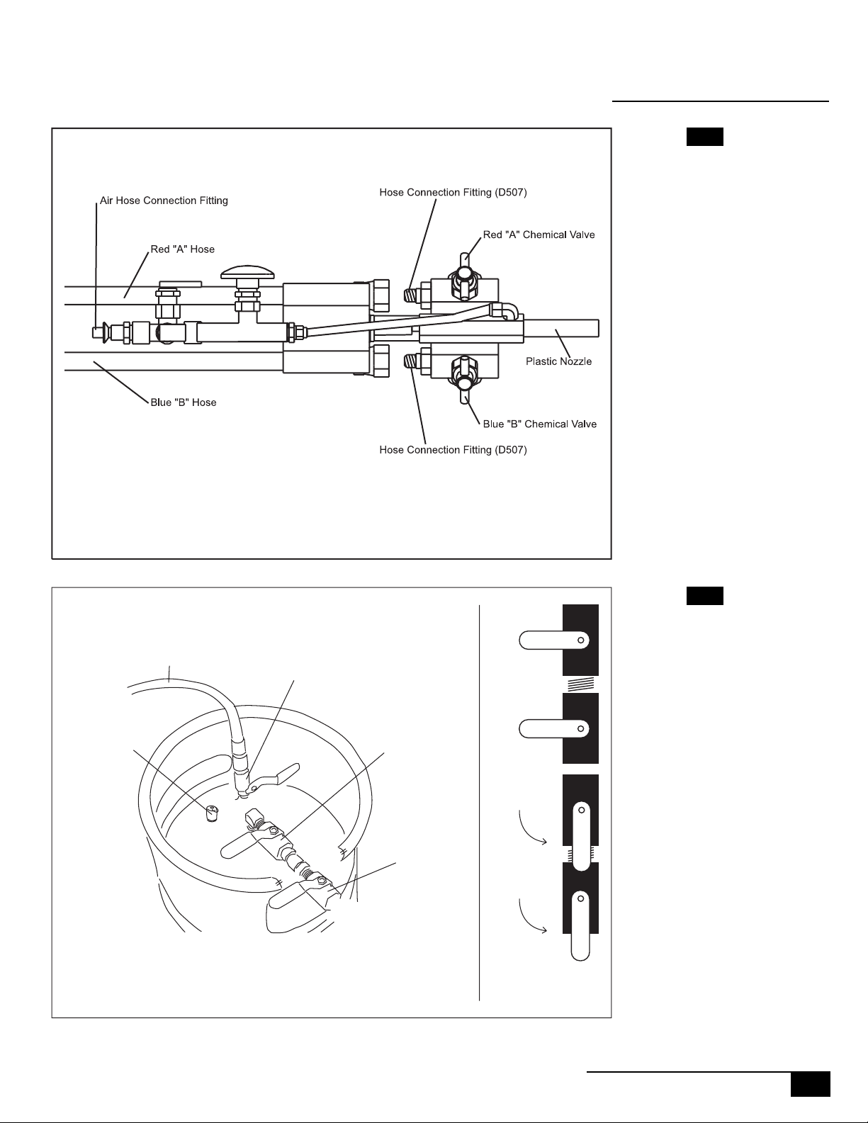
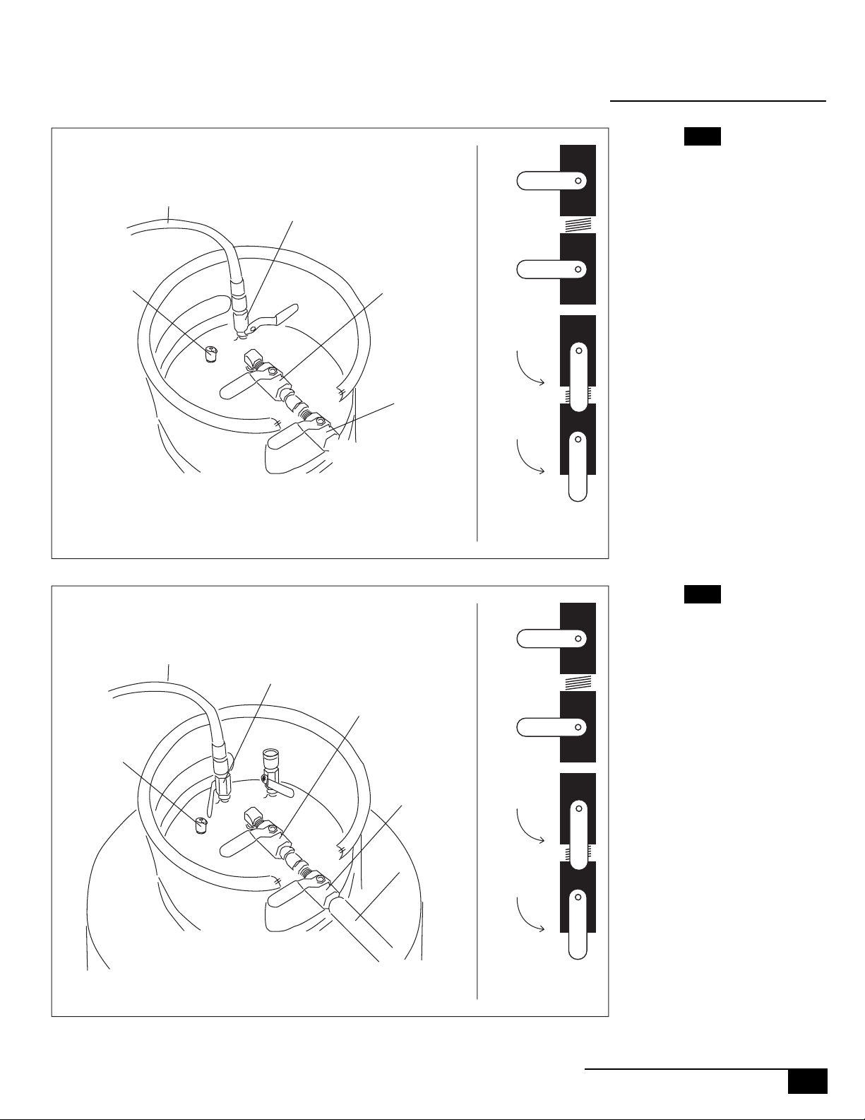
After checking to be sure all valves on the cylinder are closed, remove the
cap from the outlet of the chemical valve.
handy so that it can refitted to the cylinder after the cylinder is empty.
Remove the plug from the filter end of the red "A" hose
Keep the plug handy- it will be needed to reseal the hose after the hose
is disconnected from the cylinder.
Connect the red "A" hose to the outlet of the chemical valve on the
"A" component cylinder.
(See diagram 3B)(See diagram 3B)
(See diagram 3B) Keep the cap
(See diagram 3B)(See diagram 3B)
(See diagram 3B)(See diagram 3B)
(See diagram 3B).
(See diagram 3B)(See diagram 3B)
2
FOAMPRO® F1000
©2001 R11.01
Page 4
INSTALLATION
Diagram 3A
1.2
Nitrogen
Supply
Hose
Nitrogen
Valve
Pressure
Relief
Valve
Cylinder Valves - 17 Gal.
Cylinder
Chemical
Valve
Hose Filter
Chemical
Valve
Diagram 3B
Closed
Open
Chemical
Valve
Positions:
©2001 R11.01
FOAMPRO® F1000
3
Page 5

INSTALLATION
1.2
Connecting the blueConnecting the blue
Connecting the blue
Connecting the blueConnecting the blue
"B" hose to the "B""B" hose to the "B"
"B" hose to the "B"
"B" hose to the "B""B" hose to the "B"
chemical cylinder:chemical cylinder:
chemical cylinder:
chemical cylinder:chemical cylinder:
To connect the blue "B" hose to the "B" chemical cylinder: After checking to
be sure that all valves on the cylinder are closed, remove the plug from the
outlet of the chemical valve
it can be refitted to the cylinder after the cylinder is empty.
Remove the cap from the filter end of the blue "B" hose. Keep the plug handy it
will be needed to reseal the hose after the hose is disconnected from the
cylinder.
Connect the blue "B" hose to the outlet of the chemical valve on the "B" chemical cylinder.
Connect the dispenser air line to an air regulator 100 to 125 psi with moisture
separator and filter.
(See diagram 5A).(See diagram 5A).
(See diagram 5A). Keep the plug handy so that
(See diagram 5A).(See diagram 5A).
NONO
NO
NONO
1.3
Connecting theConnecting the
Connecting the
Connecting theConnecting the
nitrogen hoses:nitrogen hoses:
nitrogen hoses:
nitrogen hoses:nitrogen hoses:
TE:TE:
TE:
TE:TE:
Compressed air that contains high levels of water or oil can adversely
affect the performance and service life of some of the parts of the
Foampro dispenser. This is particularly important when using portable
compressors. Be sure to drain the compressor of any water prior to use.
Also, it is recommended that an in line air filter and moisture separator are
used to remove oil from the compressed air source.
Place the nitrogen cylinder near the chemical cylinders, being sure to secure the
nitrogen cylinder so that it cannot be accidentally knocked over.
Connect the nitrogen regulator to the nitrogen cylinder using the threaded
pressure fitting on the rear of the nitrogen regulator assembly.
(See diagram 5B)(See diagram 5B)
(See diagram 5B)
(See diagram 5B)(See diagram 5B)
Connect the red hose leading from the nitrogen regulator assembly to the
nitrogen fitting on the "A" chemical cylinder . It will be fitted with a quick
connect fitting that will simply snap into place.
page)page)
page)
page)page)
(See diagram 3B, previous(See diagram 3B, previous
(See diagram 3B, previous
(See diagram 3B, previous(See diagram 3B, previous
Connect the blue hose leading from the nitrogen regulator assembly to the
nitrogen fitting on the "B" chemical cylinder. It will be fitted with a quick
connect fitting that will simply snap into place.
4
FOAMPRO® F1000
(See diagram 5A)(See diagram 5A)
(See diagram 5A)
(See diagram 5A)(See diagram 5A)
©2001 R11.01
Page 6
Pressure
Relief
Valve
Nitrogen
Supply
Hose
Nitrogen
Valve
Cylinder
Chemical
Valve
Hose Filter
Chemical
Valve
INSTALLATION
1.3
Diagram 5A
Closed
Chemical
Cylinder Valves - 60 Gal.
Open
Filter
Chemical
Valve
Positions:
Diagram 5B
©2001 R11.01
FOAMPRO® F1000
5
Page 7

STARTUP | CALIBRATION
2.0
Make sure all installation steps have been completed prior to startup and calibration. Make sure that the chemicals are at the correct operating temperature, usually
70° to 90° F.
2.1
Startup:Startup:
Startup:
Startup:Startup:
1 | Be sure that all valves are closed.
would include: The valve on top of the nitrogen cylinder. The nitrogen valve on
top of both chemical cylinders ("A" Chemical and "B" Chemical).
grams 6A & 7A)grams 6A & 7A)
grams 6A & 7A) The chemical outlet valve on top of both chemical cylinders
grams 6A & 7A)grams 6A & 7A)
("A" chemical and "B" chemical)
on the filter end of both the red "A" component hose and the blue "B" component hose.
chemical valve on the F1000 dispenser
(See diagrams for valve locations)(See diagrams for valve locations)
(See diagrams for valve locations) This
(See diagrams for valve locations)(See diagrams for valve locations)
(See dia-(See dia-
(See dia-
(See dia-(See dia-
(See diagrams 6A & 7A)(See diagrams 6A & 7A)
(See diagrams 6A & 7A) The chemical valve
(See diagrams 6A & 7A)(See diagrams 6A & 7A)
(See diagram 6A & 7A)(See diagram 6A & 7A)
(See diagram 6A & 7A) Both the red chemical valve and the blue
(See diagram 6A & 7A)(See diagram 6A & 7A)
(See diagram 7B).(See diagram 7B).
(See diagram 7B).
(See diagram 7B).(See diagram 7B).
Diagram 6A
Nitrogen
Supply
Hose
Nitrogen
Valve
Pressure
Relief
Valve
Cylinder Valves - 17 Gal.
Cylinder
Chemical
Valve
Hose Filter
Chemical
Valve
Closed
Open
Chemical
Valve
Positions:
6
FOAMPRO® F1000
©2001 R11.01
Page 8
Pressure
Relief
Valve
Nitrogen
Supply
Hose
Nitrogen
Valve
Cylinder
Chemical
Valve
Hose Filter
Chemical
Valve
STARTUP | CALIBRATION
2.1
Diagram 7A
Closed
Chemical
Cylinder Valves - 60 Gal.
Open
Filter
Chemical
Valve
Positions:
Diagram 7B
©2001 R11.01
FOAMPRO® F1000
7
Page 9

STARTUP | CALIBRATION
2.1
2 | Turn on the air supply to the dispenser, and check for leaks.
NONO
NO
NONO
TE:TE:
TE:
TE:TE:
3 | Remove Mix Cartridge Plug (D620) if one is in place
until calibration steps are completed.
4 | Open both of the air injection valves (D704, D705)
if the air passes freely through the dispenser. Re-close both of the air injection
valves, as they must be closed to complete the calibration of the dispenser.
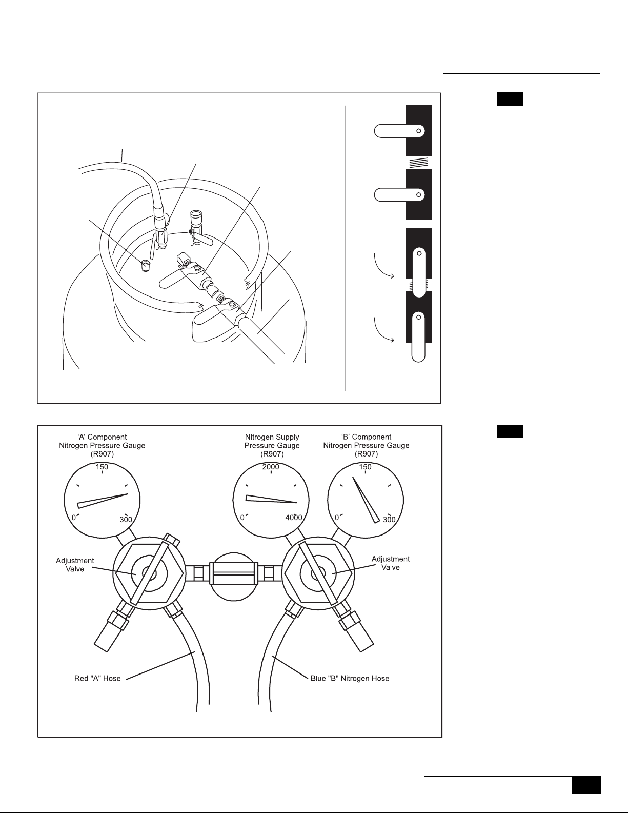
5 | Turn the adjustment valves on both nitrogen regulators leading to the "A"
chemical and the "B" chemical counterclockwise two full turns.
9B)9B)
9B)
9B)9B)
6 | Open the valve on top of the nitrogen cylinder, and check for leaks.
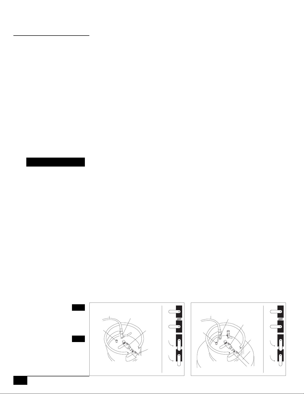
7 | Adjust the "A" component nitrogen regulator (one with the red hose) to 190
psi (starting point) by turning clockwise
8 | Adjust the "B" component nitrogen regulator (one with the blue hose) to
140 psi (starting point) by turning clockwise
The chemical cylinders are equipped with a pressure overload relief valve
that will open if the pressure of the cylinder exceeds approximately 220
psi. Do not adjust nitrogen pressure on the chemical cylinders to approach
220 psi.
(See diagram 9B)(See diagram 9B)
(See diagram 9B)
(See diagram 9B)(See diagram 9B)
(See diagram 9B)(See diagram 9B)
(See diagram 9B)
(See diagram 9B)(See diagram 9B)
. .
. Do not install nozzle
. .
(See diagram 9A)(See diagram 9A)
(See diagram 9A) to see
(See diagram 9A)(See diagram 9A)
(See diagram(See diagram
(See diagram
(See diagram(See diagram
8
FOAMPRO® F1000
©2001 R11.01
Page 10
STARTUP | CALIBRATION
2.1
Diagram 9A
Diagram 9B
©2001 R11.01
FOAMPRO® F1000
9
Page 11
STARTUP | CALIBRATION
2.1
9 | Open the nitrogen valves on both chemical cylinders ( "A" component and
"B" component).
10 | Open the chemical valves on both chemical cylinders ( "A" component and
"B" component).
fittings.
11 | Open the chemical valves on the filter end of the hose assembly for both
the "A" component and "B" component.
leaks. Tighten any leaking fittings.
12 | Position a garbage can with a plastic liner at the work area.
13 | Make sure mixing cartridge plug is removed.
14 | Open the red valve and the blue valve on the F1000 dispenser.
(See diagram 1(See diagram 1
(See diagram 1
(See diagram 1(See diagram 1
(See diagram 1(See diagram 1
(See diagram 1
(See diagram 1(See diagram 1
(See diagram 1(See diagram 1
(See diagram 1
(See diagram 1(See diagram 1
0A)0A)
0A)
0A)0A)
1A & 11A & 1
1A & 1
1A & 11A & 1
1A & 11A & 1
1A & 1
1A & 11A & 1
1B)1B)
1B)
1B)1B)
1B) 1B)
1B) Check for leaks. Tighten any leaking
1B) 1B)
(See diagram 1(See diagram 1
(See diagram 1
(See diagram 1(See diagram 1
1A & 11A & 1
1A & 1
1A & 11A & 1
1B) 1B)
1B) Check for
1B) 1B)
Diagram 10A
15 | While aiming the F1000 into the trash can, pull the trigger on the F1000
dispenser for 10 seconds, dispensing the foam into the trash can liner. If your
F1000 is brand new, you may have to pull the trigger for a longer period to
purge the air out of the hoses. If your F1000 dispenser was put into storage
with the hoses full of chemicals, you may have to dispense foam for longer than
10 seconds to be sure that the chemicals that were stored in the hoses is fully
flushed out by fresh chemicals from the chemical cylinders.
10
FOAMPRO® F1000
©2001 R11.01
Page 12
Nitrogen
Supply
Hose
Nitrogen
Valve
STARTUP | CALIBRATION
2.2
Diagram 11A
Closed
Pressure
Relief
Valve
Cylinder Valves - 17 Gal.
Pressure
Relief
Valve
Nitrogen
Supply
Hose
Nitrogen
Valve
Cylinder
Chemical
Valve
Hose Filter
Chemical
Valve
Cylinder
Chemical
Valve
Hose Filter
Chemical
Valve
Open
Chemical
Valve
Positions:
Diagram 11B
Closed
©2001 R11.01
Chemical
Cylinder Valves - 60 Gal.
Filter
Open
Chemical
Valve
Positions:
FOAMPRO® F1000
11
Page 13

STARTUP | CALIBRATION
2.2
Calibration ofCalibration of
Calibration of
Calibration ofCalibration of
A:B ratio:A:B ratio:
A:B ratio:
A:B ratio:A:B ratio:
Proper mixing of the “A” and “B” component chemicals in the correct proportions is important in producing foam. Foams produced with an improper proportion of “A” to “B” chemical can in some cases affect foam properties.
When and how often should the A:B ratio be checked?
•At the beginning of the workday.
•When a new cylinder of “A” or “B” component is installed.
•When a new cylinder of nitrogen is installed.
•About halfway through the normal workday.
•When the temperature in the work area increases or decreases by more
than 10 degrees. If the temperature of the chemicals changes, the viscosity
of the chemicals changes. This viscosity change can have an effect on the
A:B ratio.
•If a noticable change takes place in the foam being produced.
•After any restriction in the chemical flow is removed, for example cleaning
the filters or the ports in the mixing cartridge in the F1000 will likely
increase the flow of chemical which in turn may change the A:B ratio.
•When a new mixing cartridge is installed.
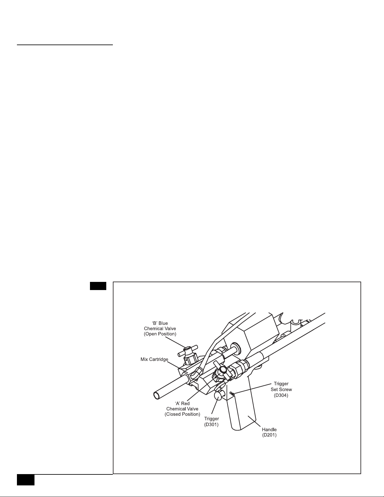
1 | Make sure that the F1000 dispenser is correctly installed to the chemical
cylinders, nitrogen cylinders, and compressed air supply as described in the
Startup procedures above. Check all hose connections to be sure that there are
no leaks. Make sure the air injection on/off valve is closed. For calibration,
remove the plastic nozzle.
(See diagram 13A)(See diagram 13A)
(See diagram 13A)
(See diagram 13A)(See diagram 13A)
12
FOAMPRO® F1000
2 | Place a 32oz paper cup on a scale, and tare the scale to read zero.
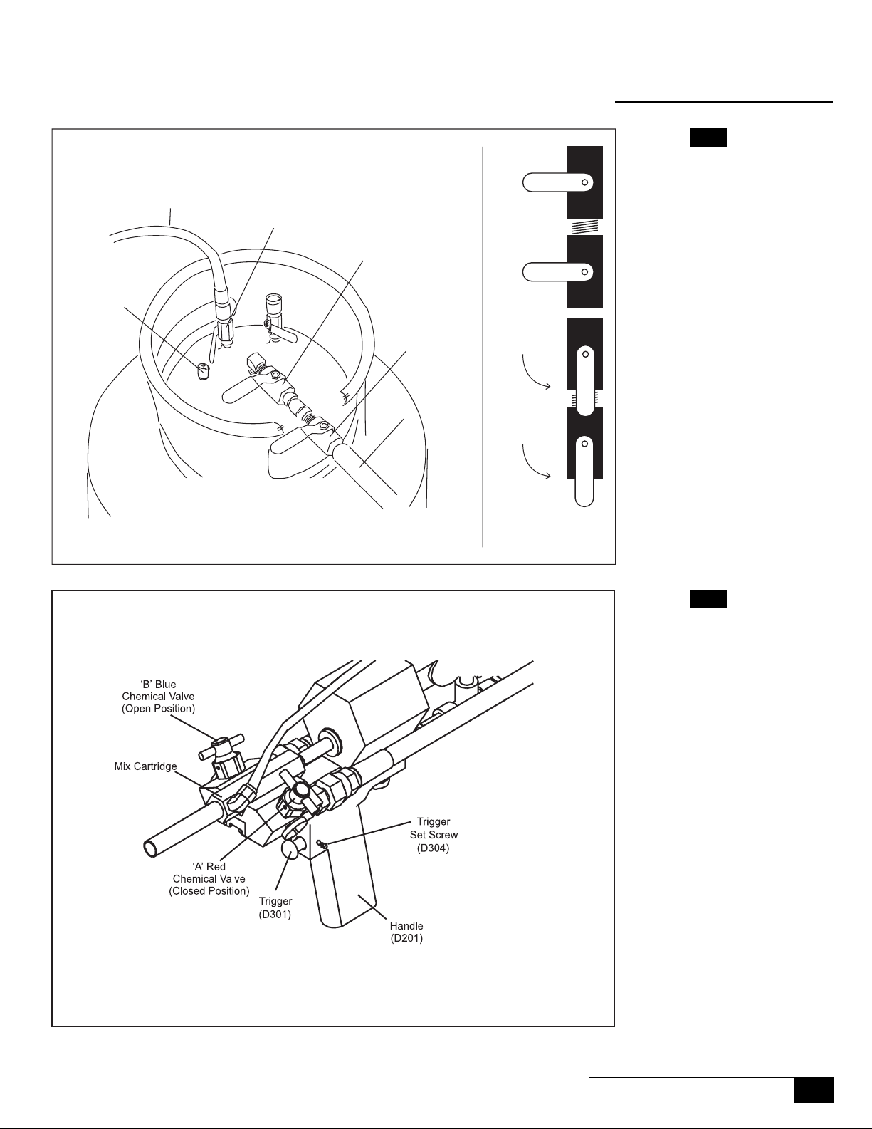
3 | Open the "A" (red) chemical valve and close the "B" chemical (blue) valve on
the F1000 dispenser.
4 | Using a stop watch, or optional timer, trigger the F1000 dispenser for exactly
3 seconds, directing the flow of the "A" chemical into the paper cup on the
scale. Record the weight of "A" chemical dispensed.
5 | Critical Step- Purging the mix cartridge: After measuring the weight of
the dispensed "A" chemical in step 4, open the both "B" chemical (blue) valve
and the "A" chemical (red) valve on the F1000 dispenser.
Then, while directing the flow of the dispenser into a trash can, trigger the
F1000 dispenser for a few seconds to dispense a mixture of "A" and "B" chemicals into the trash can. This step is important because it will reduce plugging of
the mix cartridge.
(See diagram 13B)(See diagram 13B)
(See diagram 13B)
(See diagram 13B)(See diagram 13B)
(See diagram 13B)(See diagram 13B)
(See diagram 13B)
(See diagram 13B)(See diagram 13B)
©2001 R11.01
Page 14
STARTUP | CALIBRATION
2.2
Diagram 13A
Diagram 13B
©2001 R11.01
FOAMPRO® F1000
13
Page 15

STARTUP | CALIBRATION
2.2
6 | Close the "A" chemical (red) valve on the F1000 dispenser, leaving the "B"
chemical (blue) valve open.
7 | Place a 32 oz. paper cup on a scale, and tare the scale to read zero.
8 | Using a stop watch, or optional timer, trigger the F1000 dispenser for exactly
3 seconds, directing the flow of the "B" chemical into the paper cup on the
scale. Record the weight of "B" chemical dispensed.
9 | Purge the mix cartridge once again as outlined in step 5 above.
10 | Calculate the A:B chemical ratio by dividing the weight of the "A" chemical
obtained from step 4 by the weight of the "B" chemical obtained in step 8.
(See diagram 15A)(See diagram 15A)
(See diagram 15A)
(See diagram 15A)(See diagram 15A)
Example:
"A" chemical (3 second shot) weighs 41 grams
"B" chemical (3 second shot) weighs 37 grams
41 grams ÷ 37 grams = 1.11 A:B ratio
Most Polypro formulations should be run with an A:B ratio in the range of 1.00
to 1.15. Consult the technical data sheet for the Polypro formulation you are
running- it will list the best A:B ratio for that particular product (See Ratio
Calibration Charts on pages 18 - 21).
11 | If the A:B chemical ratio obtained in step 10 is too high, ie above 1.15,
adjust the nitrogen pressure on the "B" chemical up by 10 psi and repeat the
calibration procedure starting at step 1. If the A:B ratio obtained in step 10 was
too low, ie below 1.00, the adjust the nitrogen pressure on the "A" chemical up
by 10 psi and repeat the calibration procedure. It may be necessary make more
than one adjustment to the nitrogen pressure of the "B" chemical before reaching the correct A:B ratio. It is advisable to adjust the nitrogen pressure on the
B" component in order to adjust the A:B ratio, not the nitrogen pressure on the
"A" chemical.
12 | It may be necessary during the calibration process to reduce the nitrogen
pressure on one of the chemical cylinders. This situation occurs when the proper
A:B component ratio cannot be achieved without raising the pressure on one of
the cylinders to its maximum pressure of 220 psi. REMEMBER: Each of the
chemical cylinders is equipped with a pressure relief valve that will automatically open if the nitrogen pressure on the cylinder exceeds 220 psi.
14
FOAMPRO® F1000
Use the following steps to reduce nitrogen pressure on the cylinder. SAFETY
GLASSES SHOULD BE WORN DURING THIS PROCEDURE.
©2001 R11.01
Page 16
STARTUP | CALIBRATION
2.2
Diagram 15A
©2001 R11.01
FOAMPRO® F1000
15
Page 17
STARTUP | CALIBRATION
2.2
1 - Close nitrogen valve on the chemical cylinder.
2 - Using the nitrogen pressure adjustment valve for the chemical cylinder
being adjusted, turn the adjustment valve counterclockwise two full turns.
(See diagram 17A)(See diagram 17A)
(See diagram 17A)
(See diagram 17A)(See diagram 17A)
3 - Locate the pressure relief valve on the chemical cylinder being adjusted.
(See diagrams 16A & 16B)(See diagrams 16A & 16B)
(See diagrams 16A & 16B)
(See diagrams 16A & 16B)(See diagrams 16A & 16B)
4 - Pull upward on the ring of the pressure relief valve for 2 or 3 seconds, then
release the ring to allow the valve to close. A burst of pressure will escape from
the valve.
5 - Open the nitrogen valve on the chemical cylinder.
16B)16B)
16B)
16B)16B)
6 - Using the nitrogen pressure adjustment valve for the chemical cylinder
being adjusted, turn the valve clockwise to the desired pressure.
(See diagram 17A)(See diagram 17A)
(See diagram 17A)
(See diagram 17A)(See diagram 17A)
Following these steps should result in a decrease in the pressure on the chemi-
NONO
NO
NONO
TE:TE:
TE:
TE:TE:
cal cylinder.
(See diagrams 16A & 16B)(See diagrams 16A & 16B)
(See diagrams 16A & 16B)
(See diagrams 16A & 16B)(See diagrams 16A & 16B)
(See diagrams 16A &(See diagrams 16A &
(See diagrams 16A &
(See diagrams 16A &(See diagrams 16A &
Diagram 16A
(Left)
Diagram 16B
(Right)
The chemical cylinders are equipped with a pressure overload relief valve
that will open if the pressure of the cylinder exceeds approximately 220
psi. Do not adjust nitrogen pressure on the cylinders to approach 220 psi.
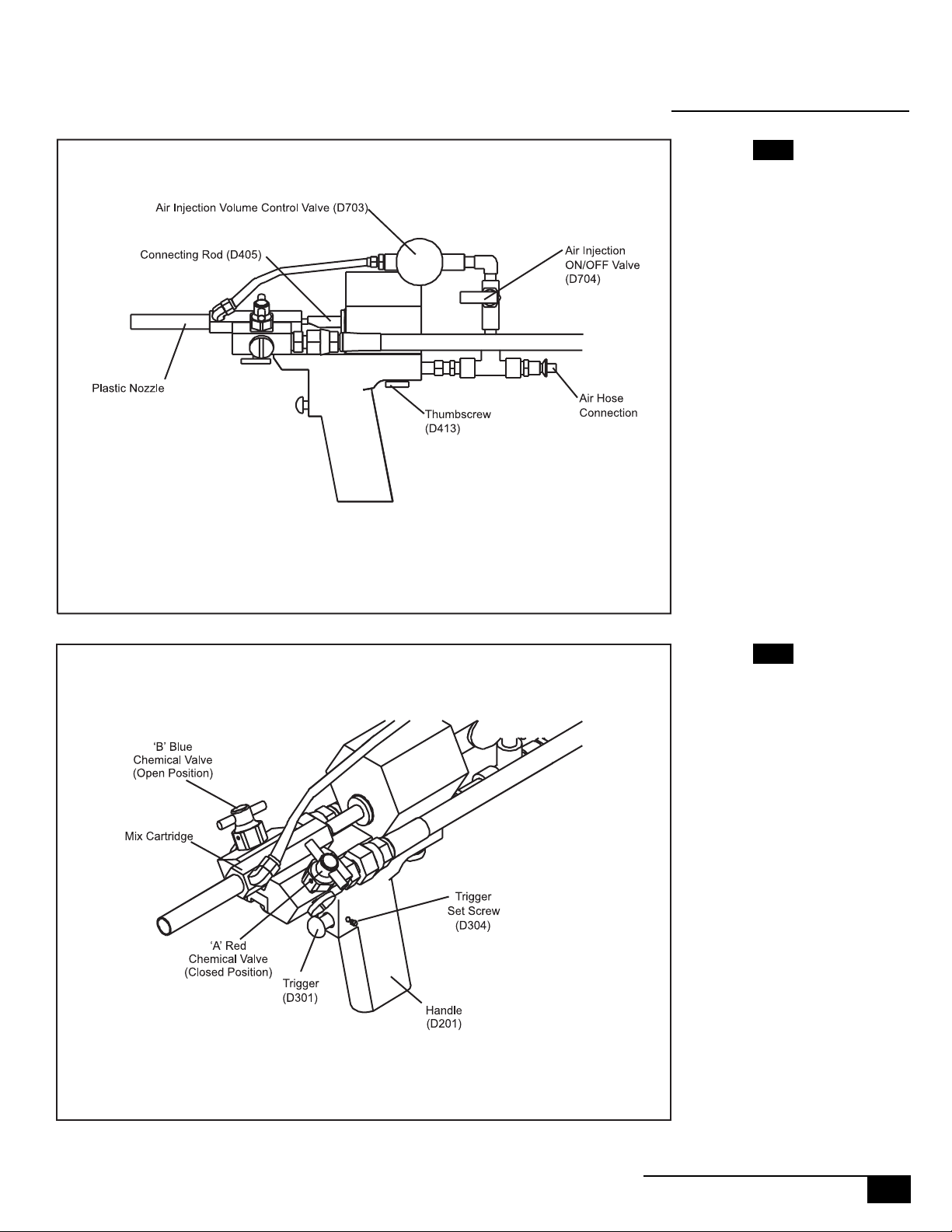
Before using the F1000 dispenser, you will need to install the plastic nozzle onto
the Mix Cartridge. The valves on the Air Injection System will have to be opened so
that air is passing freely.
The Air Injection System is comprised of two valves, an On/Off Valve (D704) and a
Needle Valve (D703) that are connected to the F1000 by a series of simple 1/8”
fittings. (See Diagram 17B) The Air Injection System serves three purposes. The air
flowing into the Mix Cartridge (D603) helps:
• the mixing of the “A” and “B” chemicals
• propel the chemicals out of the nozzle,
• keep the Mix Cartridge (D603) clear of curing foam.
The Needle Valve (D703) can be adjusted by turning the knob to control the amount
Pressure
Relief
Valve
Nitrogen
Supply
Hose
Nitrogen
Valve
Cylinder
Chemical
Valve
Hose Filter
Chemical
Valve
Closed
Open
Pressure
Relief
Valve
Nitrogen
Supply
Hose
Nitrogen
Valve
Cylinder
Chemical
Valve
Hose Filter
Chemical
Valve
Chemical
Filter
Closed
Open
16
FOAMPRO® F1000
Cylinder Valves - 17 Gal.
Chemical
Valve
Positions:
Cylinder Valves - 60 Gal.
Chemical
Valve
Positions:
©2001 R11.01
Page 18
STARTUP | CALIBRATION
of air flowing through the system. Different uses of the F1000, for example spraying
foam, may require a higher flow of air than pouring foam. Experience in using the
F1000 will help the user determine what air flow level suits their needs.
Once the proper amount of airflow through the Air Injection System has been
achieved, the F1000 dispenser is ready for use. Foam product can be dispensed by
depressing the trigger.
After using the F1000 dispenser, if it is to momentarily sit idle for more than a few
minutes, either let air flow through the Air Injection System, or place a few drops of
solvent into the open end of the plastic nozzle. Keep the plastic nozzle pointed
upward so the solvent remains and prevents any foam product from curing in the
end of the nozzle or mix cartridge. If the F1000 dispenser is to be shut down or
stored for a long period of time, follow the procedure for Shutdown described in
Section 4.1.
Diagram 17A
2.2
©2001 R11.01
Diagram 17B
FOAMPRO® F1000
17
Page 19

STARTUP | CALIBRATION
2.2
Three second shot of "A" Three second shot of "B" Approximate Total Output
Grams of "A" Component FROM - Grams of "B" component - TO in Pounds per minute
30 26.1 28.6 2.5
31 27.0 29.5 2.6
32 27.8 30.5 2.7
33 28.7 31.4 2.8
34 29.6 32.4 2.9
35 30.4 33.3 2.9
36 31.3 34.3 3.0
37 32.2 35.2 3.1
38 33.0 36.2 3.2
39 33.9 37.1 3.3
40 34.8 38.1 3.4
41 35.7 39.0 3.4
42 36.5 40.0 3.5
43 37.4 41.0 3.6
44 38.3 41.9 3.7
45 39.1 42.9 3.8
46 40.0 43.8 3.9
47 40.9 44.8 4.0
48 41.7 45.7 4.0
49 42.6 46.7 4.1
50 43.5 47.6 4.2
51 44.3 48.6 4.3
52 45.2 49.5 4.4
53 46.1 50.5 4.5
54 47.0 51.4 4.5
55 47.8 52.4 4.6
56 48.7 53.3 4.7
57 49.6 54.3 4.8
58 50.4 55.2 4.9
59 51.3 56.2 5.0
60 52.2 57.1 5.0
61 53.0 58.1 5.1
62 53.9 59.0 5.2
63 54.8 60.0 5.3
64 55.7 61.0 5.4
65 56.5 61.9 5.5
66 57.4 62.9 5.6
67 58.3 63.8 5.6
68 59.1 64.8 5.7
69 60.0 65.7 5.8
70 60.9 66.7 5.9
18
FOAMPRO® F1000
©2001 R11.01
Page 20

STARTUP | CALIBRATION
2.2
Three second shot of "A" Three second shot of "B" Approximate Total Output
Grams of "A" Component FROM - Grams of "B" component - TO in Pounds per minute
71 61.7 67.6 6.0
72 62.6 68.6 6.1
73 63.5 69.5 6.1
74 64.3 70.5 6.2
75 65.2 71.4 6.3
76 66.1 72.4 6.4
77 67.0 73.3 6.5
78 67.8 74.3 6.6
79 68.7 75.2 6.6
80 69.6 76.2 6.7
81 70.4 77.1 6.8
82 71.3 78.1 6.9
83 72.2 79.0 7.0
84 73.0 80.0 7.1
85 73.9 81.0 7.1
86 74.8 81.9 7.2
87 75.7 82.9 7.3
88 76.5 83.8 7.4
89 77.4 84.8 7.5
90 78.3 85.7 7.6
91 79.1 86.7 7.7
92 80.0 87.6 7.7
93 80.9 88.6 7.8
94 81.7 89.5 7.9
95 82.6 90.5 8.0
96 83.5 91.4 8.1
97 84.3 92.4 8.2
98 85.2 93.3 8.2
99 86.1 94.3 8.3
100 87.0 95.2 8.4
101 87.8 96.2 8.5
102 88.7 97.1 8.6
103 89.6 98.1 8.7
104 90.4 99.0 8.7
105 91.3 100. 0 8.8
106 92.2 101. 0 8.9
107 93.0 101. 9 9.0
108 93.9 102. 9 9.1
109 94.8 103. 8 9.2
110 95.7 104. 8 9.3
111 96.5 105. 7 9.3
©2001 R11.01
FOAMPRO® F1000
19
Page 21

STARTUP | CALIBRATION
2.2
Three second shot of "A" Three second shot of "B" Approximate Total Output
Grams of "A" Component FROM - Grams of "B" component - TO in Pounds per minute
112 97.4 106. 7 9.4
113 98.3 107. 6 9.5
114 99.1 108. 6 9.6
115 100.0 109.5 9.7
116 100.9 110.5 9.8
117 101.7 111.4 9.8
118 102.6 112.4 9.9
119 103.5 113.3 10.0
120 104.3 114.3 10.1
121 105.2 115.2 10.2
122 106.1 116.2 10.3
123 107.0 117.1 10.3
124 107.8 118.1 10.4
125 108.7 119.0 10.5
126 109.6 120.0 10.6
127 110.4 121.0 10.7
128 111.3 121.9 10.8
129 112.2 122.9 10.8
130 113.0 123.8 10.9
131 113.9 124.8 11.0
132 114.8 125.7 11.1
133 115.7 126.7 11.2
134 116.5 127.6 11.3
135 117.4 128.6 11.4
136 118.3 129.5 11.4
137 119.1 130.5 11.5
138 120.0 131.4 11.6
139 120.9 132.4 11.7
140 121.7 133.3 11.8
141 122.6 134.3 11.9
142 123.5 135.2 11.9
143 124.3 136.2 12.0
144 125.2 137.1 12.1
145 126.1 138.1 12.2
146 127.0 139.0 12.3
147 127.8 140.0 12.4
148 128.7 141.0 12.4
149 129.6 141.9 12.5
150 130.4 142.9 12.6
151 131.3 143.8 12.7
152 132.2 144.8 12.8
153 133.0 145.7 12.9
154 133.9 146.7 13.0
20
FOAMPRO® F1000
©2001 R11.01
Page 22

STARTUP | CALIBRATION
2.2
Three second shot of "A" Three second shot of "B" Approximate Total Output
Grams of "A" Component FROM - Grams of "B" component - TO in Pounds per minute
155 134.8 147.6 13.0
156 135.7 148.6 13.1
157 136.5 149.5 13.2
158 137.4 150.5 13.3
159 138.3 151.4 13.4
160 139.1 152.4 13.5
161 140.0 153.3 13.5
162 140.9 154.3 13.6
163 141.7 155.2 13.7
164 142.6 156.2 13.8
165 143.5 157.1 13.9
166 144.3 158.1 14.0
167 145.2 159.0 14.0
168 146.1 160.0 14.1
169 147.0 161.0 14.2
170 147.8 161.9 14.3
171 148.7 162.9 14.4
172 149.6 163.8 14.5
173 150.4 164.8 14.5
174 151.3 165.7 14.6
175 152.2 166.7 14.7
176 153.0 167.6 14.8
177 153.9 168.6 14.9
178 154.8 169.5 15.0
©2001 R11.01
FOAMPRO® F1000
21
Page 23

MAINTENANCE | SERVICE
3.0
The F1000 has two parts of the mechanical system that can be serviced by the user.
The first is the air pressure and flow system. This system operates the mechanical
movement of the gun, and involves the following parts:
The handle, trigger, cylinder and piston assembly, and the air injection system.
3.1
SAFETY NOSAFETY NO
SAFETY NO
SAFETY NOSAFETY NO
SAFETY NOSAFETY NO
SAFETY NO
SAFETY NOSAFETY NO
Air InjectionAir Injection
Air Injection
Air InjectionAir Injection
SystemSystem
System
SystemSystem
TE:TE:
TE:
TE:TE:
TE:TE:
TE:
TE:TE:
Prior to performing any service work on the air pressure and flow system of
the F1000, be sure that the air hose to the dispenser is disconnected.
The second system of the F1000 that can be serviced by the user is the chemical
flow system, and involves the following parts:
The mix cartridge, the carrier, the on/off valves for the "A" and "B" chemicals, hose
connections and check valve assembly, and replaceable O rings and filters.
Prior to performing any service work on the chemical flow system of the
F1000, be sure that all chemical pressure on the hoses and in the gun has
been relieved. The procedure to relieve the pressure on the hoses is described in the section of this manual that covers maintenance and service
of the chemical flow system.
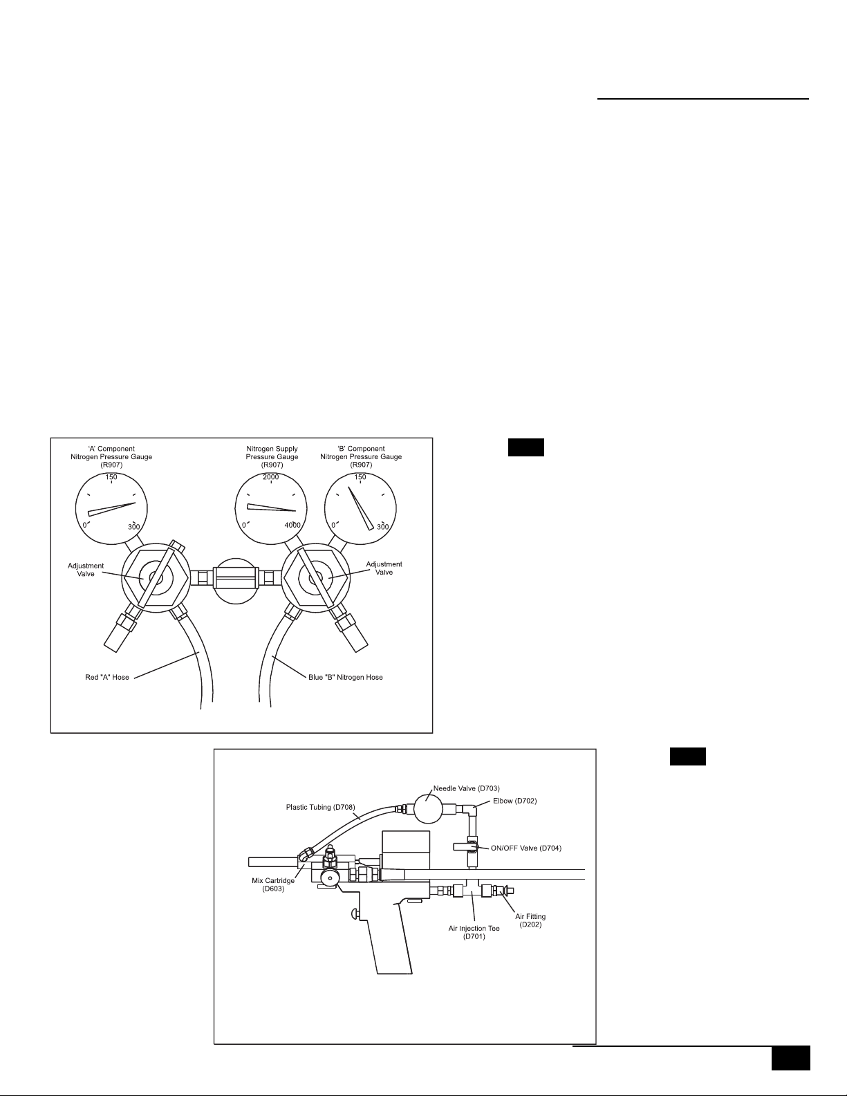
The Air Injection System is comprised of two valves, an On/Off Valve (D704) and
a Needle Valve (D703) that are connected to the F1000 by a series of simple
1/8" fittings.
poses:
(See diagram 23A)(See diagram 23A)
(See diagram 23A) The Air Injection System serves three pur-
(See diagram 23A)(See diagram 23A)
* The air flowing into the Mix Cartridge (D603) helps the mixing of the “A” and
“B” chemicals.
* The air flowing into the Mix Cartridge (D603) helps propel the chemicals out
of the nozzle, and also helps to keep the nozzle clear of curing foam.
The Needle Valve (D703) can be adjusted by turning the knob to control the
amount of air flowing through the system. Different uses of the F1000, for
example spraying foam, may require a higher flow of air than pouring foam.
Experience in using the F1000 will help the user determine what air flow level
suits their needs.
The Air Injection System should require no routine maintenance. The two valves
can be replaced if they should wear out. Care should be taken to keep the Air
Injection System free of obstructions. Triggering the F1000 without removing
the Mix Cartridge Plug (D620) can cause foam to back flow into the Air Injection System, which will block it. In this situation the two Valves (D703, D704),
and associated air fittings have to be replaced. Extreme cases of this backflow
have caused foam to flow back through the Air Injection System, and into other
components of the F1000.
22
FOAMPRO® F1000
©2001 R11.01
Page 24

AIR INJECTION SYSTEM
Diagram 23A
©2001 R11.01
FOAMPRO® F1000
23
Page 25

MAINTENANCE | SERVICE
3.1.1
TT
rigger (D300)rigger (D300)
T
rigger (D300)
TT
rigger (D300)rigger (D300)
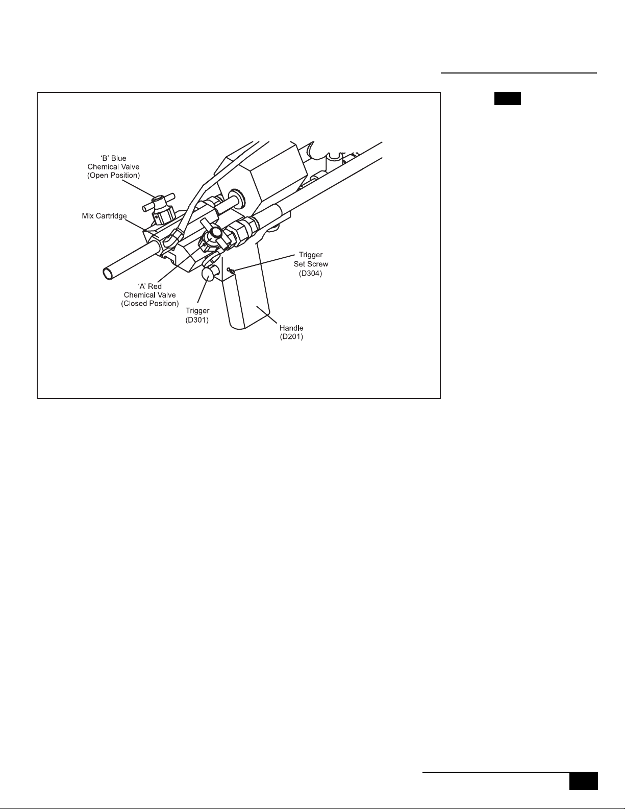
The trigger assembly is composed of six parts that fit into the handle:
diagram 25A)diagram 25A)
diagram 25A). The trigger itself (D301), the three O rings (D303) that fit onto
diagram 25A)diagram 25A)
the trigger, the trigger spring (D302), and the trigger set screw (D304). Usually
the only service required of the trigger assembly is general cleaning, replacement and lubrication of the D303 O rings or replacement of the D302 spring.
(Refer to diagram 25A)(Refer to diagram 25A)
(Refer to diagram 25A)
(Refer to diagram 25A)(Refer to diagram 25A)
1 | Using an Allen wrench, remove Trigger Set Screw (D304). The Trigger (D301)
and Trigger Spring (D302) should be easily removed. If it is stuck, gently pull it
loose, but be careful not to damage the grooves that hold the O rings.
2 | Using a dental pick or similar tool, remove the three O rings (D303) on the
Trigger (D301).
3 | Clean the Trigger (D301) and Trigger Spring (D302) of any dirt or debris.
Clean the opening in the Handle (D201) that the Trigger(D301) fits into.
4 | Replace the three O rings (D303), and lubricate them with a small amount
of O ring lubricant.
5 | Insert the Trigger Spring (D302) into the back of the Trigger (D301).
(See(See
(See
(See(See
3.1.2
Handle (D20Handle (D20
Handle (D20
Handle (D20Handle (D20
1)1)
1)
1)1)
6 | Insert the Trigger/Spring assembly into the opening in the Handle (D201),
and hold it in place, positioning it so that when the Trigger Set Screw (D304) is
reinserted into the Handle (D201) it is positioned in the groove in the Trigger/
Spring assembly.
7 | Insert the Trigger Set Screw (D304), but do not overtighten. The Trigger Set
Screw must be loose enough to allow free movement of the Trigger.
(See diagram 25B)(See diagram 25B)
(See diagram 25B) The Handle (D201) is a machined part. It will have two
(See diagram 25B)(See diagram 25B)
metal pins protruding from the top that act as alignment aids for the Air Cylinder (D401) and the Carrier (D501). These pins should not be removed.
There are also two air passageways machined into the handle that channel air
from the Trigger to the Air Cylinder (D400). The only service that can be done to
the Handle is to be sure that these air passageways do not become blocked with
debris. If the Air Cylinder (D400) is removed from the Handle (D201) for any
reason it is recommended that the two O rings (D414) that fit between the Air
Cylinder and the Handle be replaced.
24
FOAMPRO® F1000
©2001 R11.01
Page 26

AIR INJECTION SYSTEM
Diagram 25A
Diagram 25B
©2001 R11.01
FOAMPRO® F1000
25
Page 27

MAINTENANCE | SERVICE
3.1.3
Air Cylinder/ PistonAir Cylinder/ Piston
Air Cylinder/ Piston
Air Cylinder/ PistonAir Cylinder/ Piston
Assembly (D400)Assembly (D400)
Assembly (D400)
Assembly (D400)Assembly (D400)
(See diagram 27A, 27B)(See diagram 27A, 27B)
(See diagram 27A, 27B) The Air Cylinder/ Piston Assembly (D400) is composed
(See diagram 27A, 27B)(See diagram 27A, 27B)
of eight basic parts:
The Cylinder Body (D401)
The Piston (D402)
The Piston Set Screw (D403)
The Connecting Rod (D405)
The Back Plate (D410)
The Back Plate Retaining Ring (D412)
The Bushing (D406)
The Bushing C-Clip (D409)
The Thumbscrew (D413)
There are six O rings associated with this assembly:
Inside Bushing O Ring (D407)
Outside Bushing O ring (D408)
(2) Piston O Rings (D404)
Connecting Rod O Ring (D602)
Back Plate O Ring (D410)
26
FOAMPRO® F1000
©2001 R11.01
Page 28

AIR INJECTION SYSTEM
Diagram 27A
Diagram 27B
©2001 R11.01
FOAMPRO® F1000
27
Page 29

MAINTENANCE | SERVICE
3.1.3
Air Cylinder/ PistonAir Cylinder/ Piston
Air Cylinder/ Piston
Air Cylinder/ PistonAir Cylinder/ Piston
Assembly (D400)Assembly (D400)
Assembly (D400)
Assembly (D400)Assembly (D400)
1 | Before removing the Air Cylinder/Piston Assembly (D400) from the F1000,
first be sure that the Connecting Rod (D405) is fully extended out from the Air
Cylinder Body (D401). This would be its normal position when the F1000 is NOT
dispensing foam.
2 | On the Air Injection System, disconnect the plastic tubing where it enters
the air fitting on the side of the Mix Cartridge (D603 or other optional Mix
Cartridge) Do this by loosening the ferrule connection on the Tubing Elbow
(D706) and slipping the Plastic Tubing (D708) out of the ferrule. It is not necessary to remove the Tubing Elbow (D706) from the Mix Cartridge (D603).
(See diagram 29B)(See diagram 29B)
(See diagram 29B)
(See diagram 29B)(See diagram 29B)
3 | Rotate the Air Injection System so that it is perpendicular to the Handle
(D201). This is done to provide clearance for removal of the Air Cylinder/Piston
Assembly (D400).
(See diagram 29A)(See diagram 29A)
(See diagram 29A)
(See diagram 29A)(See diagram 29A)
(See diagram 29B)(See diagram 29B)
(See diagram 29B)
(See diagram 29B)(See diagram 29B)
28
FOAMPRO® F1000
©2001 R11.01
Page 30

AIR INJECTION SYSTEM
Diagram 29A
Diagram 29B
©2001 R11.01
FOAMPRO® F1000
29
Page 31

MAINTENANCE | SERVICE
3.1.3
Air Cylinder/ PistonAir Cylinder/ Piston
Air Cylinder/ Piston
Air Cylinder/ PistonAir Cylinder/ Piston
Assembly (D400)Assembly (D400)
Assembly (D400)
Assembly (D400)Assembly (D400)
4 | Loosen and remove the Thumbscrew (D413).
5 | Gently remove the Air Cylinder/ Piston Assembly (D400) from the Handle
(D201).
6 | Using a pair of snap ring pliers, remove the Back Plate Retaining Ring (D412)
from the Air Cylinder/Piston Assembly (D400).
(See diagram 3(See diagram 3
(See diagram 3
(See diagram 3(See diagram 3
1A)1A)
1A)
1A)1A)
(See diagram 30A)(See diagram 30A)
(See diagram 30A)
(See diagram 30A)(See diagram 30A)
(See diagram 3(See diagram 3
(See diagram 3
(See diagram 3(See diagram 3
1B)1B)
1B)
1B)1B)
Diagram 30A
30
FOAMPRO® F1000
©2001 R11.01
Page 32

AIR INJECTION SYSTEM
Diagram 31A
Diagram 31B
©2001 R11.01
FOAMPRO® F1000
31
Page 33

MAINTENANCE | SERVICE
3.1.3
Air Cylinder/ PistonAir Cylinder/ Piston
Air Cylinder/ Piston
Air Cylinder/ PistonAir Cylinder/ Piston
Assembly (D400)Assembly (D400)
Assembly (D400)
Assembly (D400)Assembly (D400)
7 | Push the Connecting Rod (D405) back into the Air Cylinder Body (D401) as
far as it will go. This should cause the Back Plate (D410) to be pushed out of the
Air Cylinder Body (D401). The Piston (D402) should also be accessible at this
point.
8 | Remove the Back Plate O Ring (D411) and replace it with a new O Ring.
Lubricate the new O Ring with a small amount of O Ring lubricant.
(See diagram 33A)(See diagram 33A)
(See diagram 33A)
(See diagram 33A)(See diagram 33A)
9 | Remove the Piston (D402) which will have the Connecting Rod (D405)
attached to it.
10 | Remove the two Piston O Rings (D404) and replace them with new O
Rings. Lubricate the O Rings with a small amount of O Ring lubricant.
(See diagram 33A)(See diagram 33A)
(See diagram 33A)
(See diagram 33A)(See diagram 33A)
11 | If the Connecting Rod (D405) is not severely damaged or broken, do not
remove it from the Piston (D402) instead, skip to step12. If the Connecting Rod
(D405) needs to be replaced:
(See diagram 33A)(See diagram 33A)
(See diagram 33A)
(See diagram 33A)(See diagram 33A)
(See diagram 33A)(See diagram 33A)
(See diagram 33A)
(See diagram 33A)(See diagram 33A)
(See diagram 33B)(See diagram 33B)
(See diagram 33B)
(See diagram 33B)(See diagram 33B)
* Remove Set Screw (D403) in the side of the Piston (D402)
* Remove the Connecting Rod (D405) from the Piston (D402). This may
require using a hammer and a punch to push the Connecting Rod out.
* Place a new O Ring (D602) onto the notch in the new Connecting Rod
(D405) and lubricate the Ring with a small amount of O Ring lubricant.
32
FOAMPRO® F1000
©2001 R11.01
Page 34

AIR INJECTION SYSTEM
Diagram 33A
Diagram 33B
©2001 R11.01
FOAMPRO® F1000
33
Page 35

MAINTENANCE | SERVICE
3.1.3
Air Cylinder/ PistonAir Cylinder/ Piston
Air Cylinder/ Piston
Air Cylinder/ PistonAir Cylinder/ Piston
Assembly (D400)Assembly (D400)
Assembly (D400)
Assembly (D400)Assembly (D400)
* Insert the new Connecting Rod (D405), O Ring end first, into the flat side
of the Piston (D402). This may require a fair amount of force. Make sure
that the Connecting Rod is oriented with the slot facing down as shown.
(See diagram 35A)(See diagram 35A)
(See diagram 35A). Make sure the Connecting Rod (D405) is flush with the
(See diagram 35A)(See diagram 35A)
back of the piston surface.
* Insert Set Screw (D403) in the side of the Piston and tighten fully to lock
the Connecting Rod in place.
* Lubricate the Connecting Rod (D405) with a small amount of O Ring
Lubricant. This will help in re-inserting the Connecting Rod back through
the Bushing (D406) and will extend the life of the O Rings in the Bushing
(D406).
12 | The Bushing (D406) on the front of the Air Cylinder Body (D401) contains
two O rings that may need to be replaced periodically. If the Air Cylinder/Piston
Assembly has already been disassembled for service, it would be a good idea to
replace the O rings in the Bushing (D406).
To replace the O Rings:
(See diagrams 35B and 35C)(See diagrams 35B and 35C)
(See diagrams 35B and 35C)
(See diagrams 35B and 35C)(See diagrams 35B and 35C)
* Using a pair of snap ring pliers, remove the C Clip (D409)
* Push the Bushing (D406) out from the open end of the Air Cylinder Body
(D401)
* Replace the Inner O Ring (D407) that is inside the Bushing (D406)
* Replace the Outer O Ring (D408) on the outside of the Bushing (D406)
* Insert the Bushing (D406) back into the Air Cylinder Body (D401)
* Replace the C Clip (D409) onto the Bushing (D406) to lock it in place
34
FOAMPRO® F1000
©2001 R11.01
Page 36

AIR INJECTION SYSTEM
Diagram 35A
Diagram 35C
Diagram 35B
©2001 R11.01
FOAMPRO® F1000
35
Page 37

MAINTENANCE | SERVICE
3.1.3
Air Cylinder/ PistonAir Cylinder/ Piston
Air Cylinder/ Piston
Air Cylinder/ PistonAir Cylinder/ Piston
Assembly (D400)Assembly (D400)
Assembly (D400)
Assembly (D400)Assembly (D400)
For steps 13 to 16, refer to Diagram 37A
13 | Apply a thin layer of O Ring Lubricant to the inside surface of the Air
Cylinder Body (D401)
14 | Insert the Piston into the Air Cylinder Body, making sure that the Connect-
ing Rod (D405) is positioned correctly so that it is inserted through the Bushing
(D406). Push the Piston all of the way into the Air Cylinder Body (D401).
15 | Insert the Back Plate (D410) into the Air Cylinder Body.
16 | Replace the Back Plate Retaining Ring (D412)
17 | Make sure the Mix Cartridge (D603 or other optional Cartridge) has been
properly installed. Refer to Mix Cartridge Service Procedure for instructions on
installing the Mix Cartridge.
18 | Replace the Cylinder/Handle O Rings (D414) that seal between the Handle
and the Cylinder/Piston Assembly
19 | After ensuring the Mix Cartridge is installed, position the Air Cylinder/
Piston Assembly (D400) on the Handle (D201) so that the appropriate holes in
the bottom line up with the rear alignment pin on the Handle (D201) and that
the Thumbscrew (D413) will easily thread into the bottom of the Air Cylinder/
Piston Assembly (D400). The notch in the Connecting Rod (D405) should fit over
the notch in the small rod sticking out of the Mix Cartridge (D603 or other
optional Mix Cartridge)
(See diagram 36A)(See diagram 36A)
(See diagram 36A)
(See diagram 36A)(See diagram 36A)
36
FOAMPRO® F1000
20 | Tighten the Thumbscrew (D413)
21 | Realign the Air Injection System by rotating it around back into position,
and re-connect the plastic tubing where it enters the air fitting on the side of
the Mix Cartridge (D603 or other optional Mix Cartridge)
Diagram 36A
(See diagram 37B)(See diagram 37B)
(See diagram 37B)
(See diagram 37B)(See diagram 37B)
©2001 R11.01
Page 38

AIR INJECTION SYSTEM
Diagram 37A
Diagram 37B
©2001 R11.01
FOAMPRO® F1000
37
Page 39

MAINTENANCE | SERVICE
3.2
Before performing any service work on the F1000 it is CRITICAL that all pressure of
the Chemical Flow System is relieved. Complete the following steps to relieve
pressure on the F1000.
First, make sure all of the following valves are CLOSED. (See Diagrams for valve
locations) This would include:
- The valve on top of the nitrogen cylinder
- The nitrogen valve on top of both chemical cylinders (“A” component and “B”
component)
-The chemical valve on top of both chemical cylinders (“A” component and “B”
component)
- The chemical valve on the filter end of both the red “A” component hose and
the blue “B” component hose.
-The Red “A” Chemical valve (D503R) on the F1000
-The Blue “B” Chemical valve (D503B) on the F1000
1 | Place a paper towel under the connection between the Hose Filter End Valve
and the Chemical Outlet Valve on the “A” Chemical Cylinder to catch any
dripping that will result when this connection is loosened.
2 | Using a wrench, loosen the connection between the Hose Filter End Valve to
the Chemical Outlet Valve on the “A” Chemical Cylinder, and remove the red “A”
chemical hose from the chemical cylinder. Be sure to replace the cap on the
Chemical Outlet valve.
(See diagrams 39A & 39B)(See diagrams 39A & 39B)
(See diagrams 39A & 39B)
(See diagrams 39A & 39B)(See diagrams 39A & 39B)
(See diagrams 39A & 39B)(See diagrams 39A & 39B)
(See diagrams 39A & 39B)
(See diagrams 39A & 39B)(See diagrams 39A & 39B)
(See diagrams 39A & 39B)(See diagrams 39A & 39B)
(See diagrams 39A & 39B)
(See diagrams 39A & 39B)(See diagrams 39A & 39B)
(See diagram 39A)(See diagram 39A)
(See diagram 39A)
(See diagram 39A)(See diagram 39A)
(See diagram 39A)(See diagram 39A)
(See diagram 39A)
(See diagram 39A)(See diagram 39A)
3 | Hold the Hose Filter, directing the open end into a trash can. SLOWLY open
the valve on the Hose Filter to release all of the pressure on the hose itself.
Allow the valve to remain open for at least 30 seconds.
4 | Replace the plug into the end of the Hose Filter.
5 | Place a paper towel under the connection between the Hose Filter End Valve
and the Chemical Outlet Valve on the “B” Chemical Cylinder to catch any
dripping that will result when this connection is loosened.
6 | Using a wrench, loosen the connection between the Hose Filter End Valve
and the Chemical Outlet Valve on the “B” Chemical Cylinder, and remove the
blue “B” chemical hose from the chemical cylinder. Be sure to replace the plug
in the Chemical Outlet valve
7 | Hold the Hose Filter, directing the open end into a trash can. SLOWLY open
the valve on the Hose Filter to release all of the pressure on the hose itself.
Allow the valve to remain open for at least 30 seconds.
8 | Replace the cap onto the end of the Hose Filter.
38
FOAMPRO® F1000
9 | The Chemical Flow System will now be de-pressurized and maintenance and
service of the Chemical Flow System can be safely carried out.
©2001 R11.01
Page 40

Diagram 39A
Nitrogen
Supply
Hose
CHEMICAL FLOW SYSTEM
Nitrogen
Valve
Closed
Nitrogen
Supply
Pressure
Relief
Valve
Hose
Nitrogen
Valve
Cylinder Valves - 60 Gal.
Cylinder
Chemical
Valve
Hose Filter
Chemical
Valve
Chemical
Filter
Diagram 39B
Closed
Open
Chemical
Valve
Positions:
Pressure
Relief
Valve
Cylinder Valves - 17 Gal.
Diagram 39C
Cylinder
Chemical
Valve
Hose Filter
Chemical
Valve
Open
Chemical
Valve
Positions:
©2001 R11.01
Diagram 39D
FOAMPRO® F1000
39
Page 41

MAINTENANCE | SERVICE
3.2
The chemical flow in the F1000 takes place in the Carrier Assembly (D500) and
the Mix Cartridge (D603 or other optional Mix Cartridge).
3.2.1
Carrier AssemblyCarrier Assembly
Carrier Assembly
Carrier AssemblyCarrier Assembly
(D500)(D500)
(D500)
(D500)(D500)
3.2.2
Chemical VChemical V
Chemical V
Chemical VChemical V
ServiceService
Service
ServiceService
(D503R & D503B)(D503R & D503B)
(D503R & D503B)
(D503R & D503B)(D503R & D503B)
alvealve
alve
alvealve
The parts in the Carrier Assembly (D500) are (See Diagram 41A):
Carrier Body (D501)
(2) Attachment Screws (D502)
Red “A” Valve Unit (D503R)
Blue “B” Valve Unit (D503B)
(2) Filter Screens (D504)
(2) Filter Plugs (D505)
(2) Filter Plug O Rings (D506)
(2) Hose Connectors (D507)
(2) Check Springs (D508)
(2) Check Balls (D509)
Thumbnut (D513)
2) Mix Cartridge O Rings (D602)
The Red “A” Chemical Valve (D503R) and the Blue “B” Chemical Valve (D503B)
contain O rings that can be replaced. These O Rings need to be serviced if either
of the chemical valves begin to leak. If either of the valves is damaged, the
entire valve assembly can be replaced.
Be sure that pressure on the Chemical System has been relieved before starting
this procedure. To service either of the valves:
1- Using snap ring pliers, remove the Snap Ring (D512) that holds the valve in
place.
2- Pull the Valve out from the Carrier
3- Clean the valve with solvent, then remove the three O Rings (D511) on the
valve.
4- Replace the three O Rings (D511), and lightly lubricate them with O Ring
lubricant.
5- Gently re-insert the valve into the Carrier (D501). You may have to hold the
center O Ring in place while slowly working the valve back into the Carrier
(D501). This center O Ring can be easily damaged if the valve is not gently
worked into the Carrier. Make sure that the Valve is aligned correctly so that the
valve pin stop on the Carrier is in the notch cut into the metal part of the valve.
6- Attach the Snap Ring (D512) to hold the Valve in the Carrier.
(See diagram 4(See diagram 4
(See diagram 4
(See diagram 4(See diagram 4
1B)1B)
1B)
1B)1B)
40
FOAMPRO® F1000
©2001 R11.01
Page 42

CHEMICAL FLOW SYSTEM
Diagram 41A
Diagram 41B
©2001 R11.01
FOAMPRO® F1000
41
Page 43

MAINTENANCE | SERVICE
3.2
There are two Filter Screens (D504) in the side of the Carrier (D501). One Filter
Screen is for the “A” Chemical, and the other Filter Screen is for the “B” Chemical.
These Filters are designed to catch any particulate matter that may be present from
getting into the Mix Cartridge (D603). The Filter Screens need to be cleaned periodically.
This procedure can be performed without relieving the pressure on theThis procedure can be performed without relieving the pressure on the
This procedure can be performed without relieving the pressure on the
This procedure can be performed without relieving the pressure on theThis procedure can be performed without relieving the pressure on the
Chemical Flow System, provided that the Red chemical valve (D503R)Chemical Flow System, provided that the Red chemical valve (D503R)
Chemical Flow System, provided that the Red chemical valve (D503R)
Chemical Flow System, provided that the Red chemical valve (D503R)Chemical Flow System, provided that the Red chemical valve (D503R)
and the Blue chemical valve (D503B) remain closed during the entireand the Blue chemical valve (D503B) remain closed during the entire
and the Blue chemical valve (D503B) remain closed during the entire
and the Blue chemical valve (D503B) remain closed during the entireand the Blue chemical valve (D503B) remain closed during the entire
procedure. procedure.
procedure.
procedure. procedure.
3.2.3
(See diagram 42A for location of these valves)(See diagram 42A for location of these valves)
(See diagram 42A for location of these valves)
(See diagram 42A for location of these valves)(See diagram 42A for location of these valves)
Filter ScreenFilter Screen
Filter Screen
Filter ScreenFilter Screen
ServiceService
Service
ServiceService
(D504)(D504)
(D504)
(D504)(D504)
Diagram 42A
To clean the Filter Screens:
1 | Remove the Filter Plug (D505).
(D504) is pressed onto the end of the Filter Plug (D505). The Filter Screen can be
rinsed with solvent without removing it from the Filter Plug. If the Filter Screen
(D504) is damaged, it can be pulled off the Filter Plug and replaced by pressing
a new Filter Screen onto the Filter Plug (D505).
2 | Rinse with solvent the opening on the Carrier (D501) that the Filter Screen
Plug (D505) fits into.
3 | Replace the O Ring (D506) on the Filter Plug (D505).
4 | Re-install the Filter Plug and Screen Assembly into the Carrier and tighten.
(See diagram 43A & 43B)(See diagram 43A & 43B)
(See diagram 43A & 43B) The Filter Screen
(See diagram 43A & 43B)(See diagram 43A & 43B)
42
FOAMPRO® F1000
©2001 R11.01
Page 44

CHEMICAL FLOW SYSTEM
Diagram 43A
Diagram 43B
©2001 R11.01
FOAMPRO® F1000
43
Page 45

MAINTENANCE | SERVICE
3.2
The Hose Connection Fittings (D507) that connect the “A Chemical and “B” Chemical hoses to the Carrier (D501) contain check valve mechanisms. These mechanisms
can be affected by particulate matter, or can get clogged by chemicals that may
have gelled in the check valve.
3.2.4
Check VCheck V
Check V
Check VCheck V
Assembly ServiceAssembly Service
Assembly Service
Assembly ServiceAssembly Service
alvealve
alve
alvealve
To service either of these valves:
The pressure on the Chemical Flow System must be relieved prior to performing
this procedure.
1 | Disconnect the chemical hose from the Hose Connection Fitting (D507).
Have some paper towels handy to catch any chemical that may drain from the
hose. (See Diagram 45A)
2 | Using a wrench, remove the Hose Connection Fitting (D507) from the Carrier
(D501). (See Diagram 45B)
3 | From the back side of the Hose Connection Fitting (D507), remove the Check
Spring (D508) and the Check Ball (D509). If they are stuck you may have to
push them out with a punch or similar tool.
4 | Thorougly clean the Check Ball, Check Spring, Hose Connection Fitting, and
the opening in the Carrier that the Hose Connection Fitting threads into with
solvent. You may have to scrape off any crystallized material.
5 | There is a O Ring (D408) on the Hose Connection Fitting (D507) to seal it
against the Carrier. Replace this O Ring when servicing the check valve. (See
Diagram 45B)
44
FOAMPRO® F1000
6 | Re-insert the Check Ball (D509) and Check Spring (D508) into the Hose
Connection Fitting.
7 | Thread the Hose Connection Fitting (D507) containing the Check Valve
Mechanism into the Carrier (D501) and tighten.
8 | Reconnect the chemical hose to the Hose Connection Fitting (D507) and
tighten.
©2001 R11.01
Page 46

CHEMICAL FLOW SYSTEM
Diagram 45A
Diagram 45B
©2001 R11.01
FOAMPRO® F1000
45
Page 47

MAINTENANCE | SERVICE
3.2
(See diagram 47A)
There are no user serviceable parts inside the Mix Cartridge (D603). Do not
pull the center rod out of the Mix Cartridge. Do not attempt to disassemble
the Mix Cartridge.
3.2.5
Mix CartridgeMix Cartridge
Mix Cartridge
Mix CartridgeMix Cartridge
ServiceService
Service
ServiceService
(D603 or Optional(D603 or Optional
(D603 or Optional
(D603 or Optional(D603 or Optional
Cartridge)Cartridge)
Cartridge)
Cartridge)Cartridge)
If the Mix Cartridge seizes, the rod in the center of the Mix Cartridge will not
move, and the F1000 will not operate.
If the F1000 will not move the center rod in the Mix Cartridge when the trigger
is pressed, check the following items:
1 | Make sure that the F1000 is connected to a compressed air source.
2 | Make sure that the Air Cylinder/ Piston Assembly (D400) is operating cor-
rectly. This Piston operates the Mix Cartridge, and if the Piston is stuck for any
reason, the F1000 will not move the rod in the Mix Cartridge. To determine if
the Air Cylinder/Piston Assembly is operating correctly, remove the Mix Cartridge as described in the next section, and trigger the F1000 with the Air
Cylinder/ Piston Assembly installed. If the Air Cylinder Assembly is working, but
the Mix Cartridge does not work when installed, the Mix Cartridge will have to
be replaced.
46
FOAMPRO® F1000
©2001 R11.01
Page 48

CHEMICAL FLOW SYSTEM
Diagram 47A
Diagram 47B
©2001 R11.01
FOAMPRO® F1000
47
Page 49

MAINTENANCE | SERVICE
3.2
3.2.6
Mix CartridgeMix Cartridge
Mix Cartridge
Mix CartridgeMix Cartridge
Removal andRemoval and
Removal and
Removal andRemoval and
CleaningCleaning
Cleaning
CleaningCleaning
(D603 or Optional(D603 or Optional
(D603 or Optional
(D603 or Optional(D603 or Optional
Cartridge)Cartridge)
Cartridge)
Cartridge)Cartridge)
The Ports can be cleaned by removing the Mix Cartridge from the Carrier (D501)
and cleaning the ports while they are in place.
This procedure can be performed without relieving the pressure on the Chemical
Flow System, provided that the Red chemical valve (D503R) and the Blue chemical
valve (D503B) remain closed during the entire procedure
location of these valves)location of these valves)
location of these valves). The Mix Cartridge has small ports on each side that can
location of these valves)location of these valves)
be cleaned. DO NOT REMOVE THE PORTS.
1 | Close the Red “A” Chemical Valve (D503R) and the Blue “B” Chemical Valve
(D503B) on the Carrier (D501)
2 | Clean the threaded opening in the front of the Mix Cartridge. Rinse this
opening with solvent.
3 | With the F1000 connected to a compressed air source, press the trigger and
hold it so that the center rod in the Mix Cartridge is pulled back. While the
center rod is pulled back, disconnect the compressed air from the F1000. In this
way, when the trigger is released, the center rod in the Mix Cartridge will
remain pulled back to provide access to the interior of the Mix Cartridge.
diagram 49C)
(See diagram 49C)
(See diagram 49A)
(See diagram 49A)(See diagram 49A)
(See diagram 49A)
(See diagram 49A)(See diagram 49A)
(See diagram 49C for(See diagram 49C for
(See diagram 49C for
(See diagram 49C for(See diagram 49C for
(See
4 | In order to remove the Mix Cartridge, the Air Cylinder/Piston Assembly must
be removed first. Follow steps 2 through 5 in the section “Air Cylinder/Piston
Assembly Service Procedures” to remove the Air Cylinder/Piston Assembly.
5 | Once the Air Cylinder/Piston Assembly is removed, remove the Thumbnut
(D510) on the underside of the Carrier (D501).
6 | Lift the Mix Cartridge (D603) off from the Carrier (D501).
7 | Using a Port Cleaning Pick (A1009) or a paper clip clean any debris from
each small port on the sides of the Mix Cartridge.
8 | Holding the Mix Cartridge vertically with the threaded opening on the front
of the Mix Cartridge pointed straight up, pour some solvent into the threaded
opening in the front of the Mix Cartridge. This should rinse the inside of the Mix
Cartridge, and solvent should exit the ports.
9 | Check the ports again and make sure they are clean.
10 | Do not remove or adjust ports or damage to the mix cartridge will result.
(See diagram 49D)
(See diagram 49A)
(See diagram 49B)
48
FOAMPRO® F1000
©2001 R11.01
Page 50

Diagram 49B
CHEMICAL FLOW SYSTEM
Diagram 49A
©2001 R11.01
Diagram 49D
Diagram 49C
FOAMPRO® F1000
49
Page 51

MAINTENANCE | SERVICE
3.2
3.2.6 (cont.)
Mix CartridgeMix Cartridge
Mix Cartridge
Mix CartridgeMix Cartridge
Removal andRemoval and
Removal and
Removal andRemoval and
CleaningCleaning
Cleaning
CleaningCleaning
(D603 or Optional(D603 or Optional
(D603 or Optional
(D603 or Optional(D603 or Optional
Cartridge)Cartridge)
Cartridge)
Cartridge)Cartridge)
11 | Remove the two small O Rings (D602) on the Carrier (D501).
(See diagram 5(See diagram 5
(See diagram 5
(See diagram 5(See diagram 5
12 | Clean the surfaces of the Carrier (D501) where it comes into contact with
the Mix Cartridge.
13 | Replace the two small O Rings (D602) on the Carrier (D501).
(See diagram 5(See diagram 5
(See diagram 5
(See diagram 5(See diagram 5
14 | Place the Mix Cartridge back onto the Carrier, and tighten it down using
the Thumbnut (D510), turn 1/4-turn past hand-tight.
15 | Re-install the Air Cylinder/Piston Assembly as detailed in Steps 18 through
21 in the section “Air Cylinder/Piston Assembly Service Procedure”. You may
have to manually move the Connecting Rod (D405) so that it will be correctly
positioned to attach to the center rod in the Carrier (D501).
1A)1A)
1A)
1A)1A)
1A)1A)
1A)
1A)1A)
50
FOAMPRO® F1000
©2001 R11.01
Page 52

CHEMICAL FLOW SYSTEM
Diagram 51A
©2001 R11.01
FOAMPRO® F1000
51
Page 53

SHUTDOWN
4.0
4.1
One of the unique features of the Foampro F1000 is that it can be shut down for
storage without disconnecting or flushing the chemical hoses or the dispensing gun
itself.
ShutdownShutdown
Shutdown
ShutdownShutdown
ProcedureProcedure
Procedure
ProcedureProcedure
The Foampro F1000 should be shutdown as follows:
Be sure that all valves are closed.
(See diagrams for valve locations)(See diagrams for valve locations)
(See diagrams for valve locations) This
(See diagrams for valve locations)(See diagrams for valve locations)
would include:
1 | The valve on top of the nitrogen cylinder
2 | The nitrogen valve on top of both chemical cylinders (“A” Chemical and “B”
Chemical)
(See diagrams 52A & 52B)(See diagrams 52A & 52B)
(See diagrams 52A & 52B)
(See diagrams 52A & 52B)(See diagrams 52A & 52B)
3 | The chemical valve on top of both chemical cylinders (“A” chemical and “B”
chemical)
(See diagrams 52A & 52B)(See diagrams 52A & 52B)
(See diagrams 52A & 52B)
(See diagrams 52A & 52B)(See diagrams 52A & 52B)
4 | The Chemical valve on the filter end of both the red “A” component hose
and the blue “B” component hose.
(See diagrams 52A & 52B)(See diagrams 52A & 52B)
(See diagrams 52A & 52B)
(See diagrams 52A & 52B)(See diagrams 52A & 52B)
5 | Both the red chemical valve and the blue chemical valve on the F1000
dispenser
(See diagram 53A)(See diagram 53A)
(See diagram 53A)
(See diagram 53A)(See diagram 53A)
6 | Remove plastic nozzle from the F1000 dispenser, and clean any buildup of
product from the threads in the Mix Cartridge.
52
Diagram 52A
(Left)
Diagram 52B
(Right)
FOAMPRO® F1000
7 | Holding the F1000 dispenser so that the opening in the Mix Cartridge is
pointing up, place a few drops of solvent inside the threaded area, then thread
the Mix Cartridge plug (D620) into the end of the Mix Cartridge and tighten.
The Foampro F1000 Dispenser System is now ready for storage.
The unit can be stored with the hoses connected to the chemical cylinders. If it
is desired to remove the hoses from the chemical cylinders, do the following:
Nitrogen
Supply
Hose
Pressure
Relief
Valve
Cylinder Valves - 17 Gal.
Nitrogen
Valve
Cylinder
Chemical
Valve
Hose Filter
Chemical
Valve
Closed
Open
Chemical
Positions:
Valve
Nitrogen
Supply
Hose
Pressure
Relief
Valve
Cylinder Valves - 60 Gal.
Nitrogen
Valve
Cylinder
Chemical
Valve
Hose Filter
Chemical
Valve
Chemical
Filter
Closed
Open
©2001 R11.01
Chemical
Valve
Positions:
Page 54

Note: It is not necessary to flush the hoses or empty them prior to storage.
1 | Complete the shutdown procedure detailed in Steps 1 through 7 above.
2 | Place a paper towel beneath the connection of the Hose Filter valve and the
Chemical Outlet valve on the “A” chemical cylinder.
3 | Disconnect the Hose Filter from the chemical cylinder.
4 | Replace the cap on the chemical outlet valve on the chemical cylinder, and
replace the plug in the end of the Hose Filter.
5 | Place a paper towel beneath the connection of the Hose Filter valve and the
Chemical Outlet valve on the “B” chemical cylinder.
6 | Disconnect the Hose Filter from the chemical cylinder.
7 | Replace the plug in the chemical outlet valve on the chemical cylinder, and
replace the cap on the end of the Hose Filter.
SHUTDOWN
Diagram 53A
©2001 R11.01
FOAMPRO® F1000
53
Page 55

TROUBLESHOOTING
5.0
From time to time the performance of the F1000 may vary from the optimum or
the foam produced not meet the desired characteristics. Below is a list of
symptoms and a series of checks to restore proper perfomance. (Page number
references follow procedures).
1 | Gun doesn’t activate; mixing cartridge rod does not move when the trigger
is pulled:
Make sure the compressed air line is correctly connected and pressurized (2)
Check operation of air cylinder piston assembly (46)
Check operation of mixing cartridge (46)
2 | Chemicals are not dispensing, but gun is activating (mixing cartridge rod
moves when trigger is pulled):
Make sure mixing cartridge is not plugged (48)
Make sure nozzle is not plugged (10, 11)
Make sure valves on chemical tanks and hose end filter are open (10, 11)
Make sure red and blue chemical valves on gun are open (10, 11)
Make sure nitrogen pressure is on (10, 11)
Check filter on gun for blockage (42)
Check mixing cartridge orifices for blockage (48)
3 | Cannot reach proper A:B chemical ratio calibration:
Make sure chemical valves on gun and chemical tanks are open (10, 11)
Make sure nitrogen is connected properly (8)
Make sure nitrogen valve on both “A” and “B” chemical tanks
are open (10, 11)
Make sure proper procedure for calibration is followed (12)
Check for blockages in chemical flow:
Filter under gun (42)
Mixing cartridge (48)
Check valve assembly (44)
4 | Pressure relief valve on chemical tank is venting pressure:
Reduce nitrogen pressure on chemical tank (14, 16)
5 | Foam dispensed dosen’t “look right”:
Foam is sticky, spongy or is shrinking over time - check A:B ratio calibration.
Usually this is caused by an excess of “B” component. (12)
Foam is brittle or crunchy - check A:B ratio calibration. Usually this is
caused by an excess of “A” component. (12)
54
FOAMPRO® F1000
©2001 R11.01
Page 56

Assembly Description
HANDLE
D200 Handle, Fully Assembled
D201 FP100A handle
D202 1/8" air fi tting
D301 Trigger
D302 Trigger Spring
D303 Trigger O Ring
D304 Trigger Set Screw
D291 Handle Cover Plate
AIR CYLINDER
D400 Air Cylinder, Assembled
D401 Cylinder Body
D402 Piston
D403 Set Screw
D404 Piston O Ring
D405 Connecting Rod
D406 Bushing
D407 Inside Bushing O Ring
D408 Outside Bushing O Ring
D409 Bushing C Clip
D410 Back Plate
D411 Back Plate O Ring
D412 Back Plate C Clip
D413 Thumbscrew
D414 Cylinder- Handle O Ring
Service Parts D415 Air Cylinder Repair Kit
Service Parts D416 Bushing Repair Kit
D602 O Ring
PARTS LIST
6.0
©2001 R11.01
CARRIER
D500 Carrier (Ass embled)
D501 Carrier Body
D502 Attachment Screw
D503R Red "A" Valve Unit
D503B Bl ue "B" Valve Unit
D504 Filter Screen
D505 Filter Plug
D506 Filter Plug O Ring
D507 Hose Connector
D508 Check Spring
D509 Check Ball
D510 Thumbnut
Service Part D511 Valve O Ring Kit
Service Part D513 Valve Pin Stop
FOAMPRO® F1000
55
Page 57

PARTS LIST
6.0
MIX CARTRIDGE
D603 Mix Cartridge, Standard Output
D620 1/4" Plug
AIR INJECTION
D701 1/8" Air Injection Tee
D702 1/8" Elbow
D703 Needle Valve
D704 Air On-Off Valve
D705 1/8" air nipple
D706 Cartridge Tubing Elbow
D707 1/8" Tubing Adaptor
D708 1/4" plastic tubing
HOSE SYSTEM
H806 Filter Unit
H807 1/2" Valve
H811 20 Ft Hose Bundle, 3/8"
H870 Hose End Plug
H871 Hose End Cap
REGULATOR SYSTEM
R900 Regulator System, Fully Assembled
R905 Pressure Relief Valve
R906 4000 PSI Gauge
R907 300 PSI Gauge
R908R 10 Ft. Nitrogen Hose, Red
R908B 10 Ft. Nitrogen Hose, Bl ue
56
FOAMPRO® F1000
©2001 R11.01
 Loading...