

Page 1
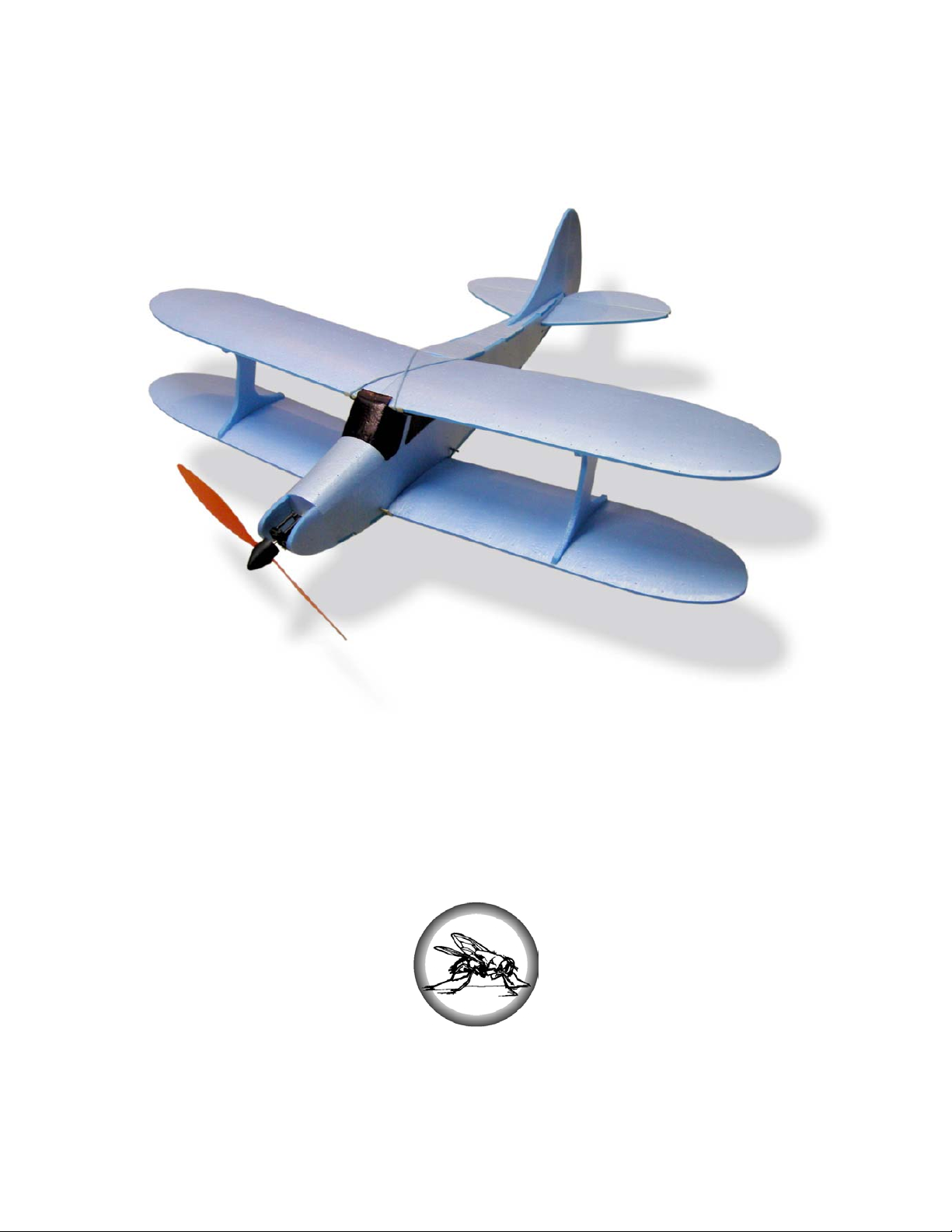
StaggerW i n g
Instruction Manual
Electric Foam Slowflyer with “Zipper Method©” construction.
Designed By: Daniel J. Schwartz
Available Exclusively from:
www.FoamFly.com
4077 WoodCreek Dr.
Ypsilanti MI. 48197
USA
© 2003 FoamFly.com
Page 2
Thank You for purchasing the FoamFly Staggerwing! Welcome to
the world of simple, durable foam flying machines. The Staggerwing is sure to
thrill, with it’s sleek styling, and old-timer flair. This plane is suitable for
beginners, but it is recommended that new pilots get the help of an instructor to
trim their plane, and help with the first flights.
Almost anybody can fly the Staggerwing. It’s as easy to build, and more
durable than pre-fab planes that you might find at the hobby shop. But you build
this yourself. In addition to the well earned pride, you’ll have a complete
understanding of the structure, and if it should ever need repair, you’ll be able to
do it yourself without costly replacement wings and cowlings.
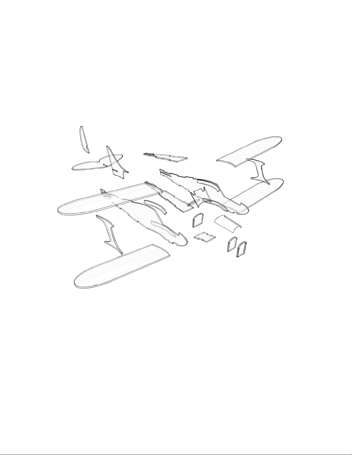
The “Zipper Method©” Construction makes the plane quick and easy to
assemble. All the pieces are specially designed to interlock, and are computer
cut so that they fit perfectly every time.
Staggerwing Specs:
• WingSpan: 31.5”
• Length: 25” (26.5” Including Prop and Spinner)
• Wing Area: 268 Square Inches (1.86 Sq. Ft.)
• Ready To Fly Weight 7-9 Oz.
• Motor: GWS IPS-A (5.86:1 Gear Ratio)
• Propeller: 9x7, or 10x4.7 (9x7 Recommended)
• Batteries: 950mAh “HippoBatt” Lithiums, 2-cell
1020mAh Kokams, or 6-7 cell 300mAh
NiMHs. Basically any 1.5 – 2.8 Oz battery.
• Receiver: GWS R4P (4 Channel)
• Servos: GWS Pico BB (or Hitec HS-50)
• ESC: GWS IS-50 (2-Amp Speed Control)
©2003 FoamFly.com 2
Page 3

Introduction:
FoamFly.com is more than just a hobby company. It’s a community too!
Please take pictures of your Staggerwing, and upload them to the photo gallery.
Feel free to drop by and see what all the other foam junkies have been building.
There are free plans, and lot’s of tips and ideas as well as unique new planes
that you won’t find anywhere else.
Okay, you’ve got your Staggerwing kit in front of you, and you’re ready to
cruise the skies. Only problem: the plane is lying in pieces in front of you. Well
we can take care of that too. There’s some techniques you’ll need to be familiar
with to make the most of your kit. I’ll refer to them as they’re needed, but the
details of those techniques will be in the Appendix at the end of this manual.
Let’s begin. Don’t let all the text in this manual scare you. Take each
step taken one at time, and you’ll find that everything is within your capabilities.
Here we go.
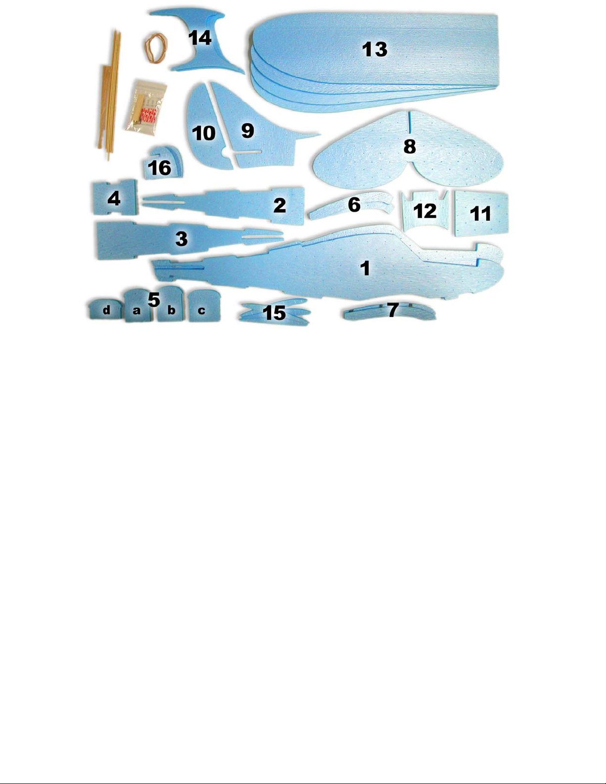
1) Cut out all the parts: (Kit builders will find this step all done for them.)
You’ll need to know which part is which, unless you want to end up with the
flying equivalent of Frankenstein’s Monster. So, let’s start by taking a look at
what you’ve got here.
a) Foam Airplane Parts:
(1) Fuselage halves (Left and Right)
(2) Fuselage Top
(3) Fuselage Bottom
(4) Fuselage Front
(5) Formers:
(a) Firewall Front
(b) Firewall Rear
(c) Hood
(d) Windshield
(6) Upper Wing Saddle Doublers (2)
(7) Lower Wing Saddle Doublers (2)
(8) Horizontal Stabilizer
(9) Vertical Stabilizer
(10) Rudder
(11) Hood (Battery Door)
(12) Windshield
(13) Wings (4, 2 Left, and 2 Right)
(14) Wing Struts (2, Left and Right)
(15) Optional: Landing Gear Mount
(16) Foam Tools: Dihedral Jig (2)
There’s a few foam parts in the kit, that aren’t destined to be
part of the plane.
©2003 FoamFly.com 3
Page 4
And of course even a foam plane needs a few odds and ends to tie
everything together. Take a few moments to inspect what you’ve you’ll need
here. As the items are called for you’ll get more info on their intended uses.
b) Non-Foam Parts:
i) Bamboo Skewers (4)
ii) Wood Motor Mount
iii) Laser Cut Control Horns http://www.FoamFly.com/accessories.htm
iv) 18” x .032” Wire for pushrods (2)
v) 3/16” x 1/32” Wood Elevator Joiner/Wing Reinforcement (3)
vi) Double Stick Servo/Receiver tape (3)
vii) Wing Mounting Rubberbands (6)
viii) .055” Wire for Landing Gear
Now we get to begin the process. Before you cut or glue anything, I’ll say
this: Due to the nature of the raw materials available, you’ll notice that most of
the pieces have printing on one side. Now, you can do what you want, but I
recommend planning ahead so that you put all the printing towards the inside of
the plane. ;)
©2003 FoamFly.com 4
Page 5
2) Fuselage:
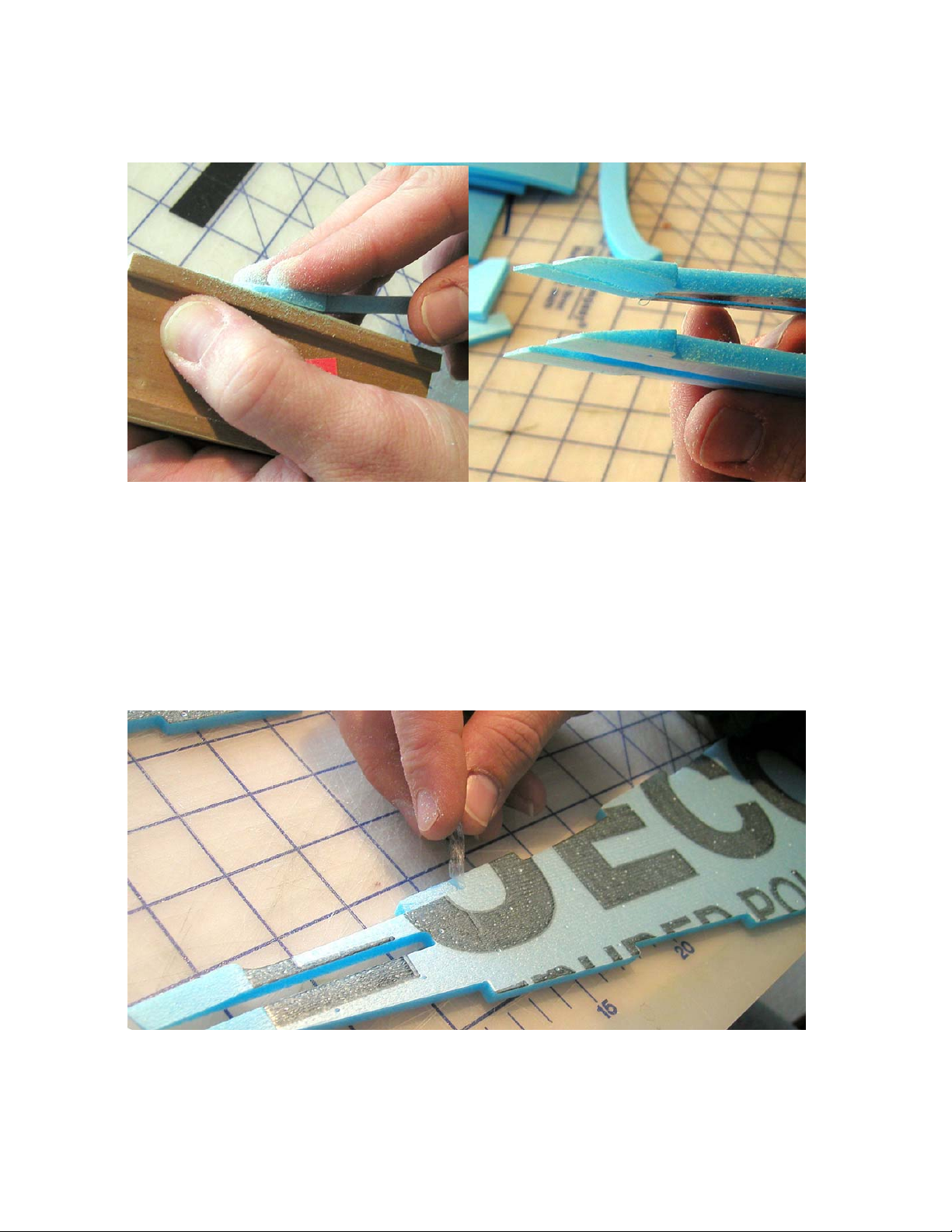
a) Taper the Rear end of the Fuselage Sides.
The Fuselage comes to a smooth tapered finish so you’ll need to shave
down the foam at the end of the Fuselage on the insides. From the
beginning of the last two tabs to the end taper the foam from full thickness to
razor thin with a knife or sandpaper. (See the Appendix section, “Tapers
and Angled cuts”)
b) Peel the insides of the tabs
After you’ve figured out which sides of the fuselage parts will be on the
inside of the plane, you need to peel the skin off the protruding tabs of each
of the following parts. (See the Appendix section, “Cut & Peel”)
i) Fuse Sides
ii) Fuse Top
iii) Fuse Bottom
iv) Fuse Front
c) Also Peel the fuse sides where the formers will glue.
You’ll also need to pull the skin off in the areas where the Firewall, and
Hood will glue to the insides of the fuselage. (See the plans.)
©2003 FoamFly.com 5
Page 6
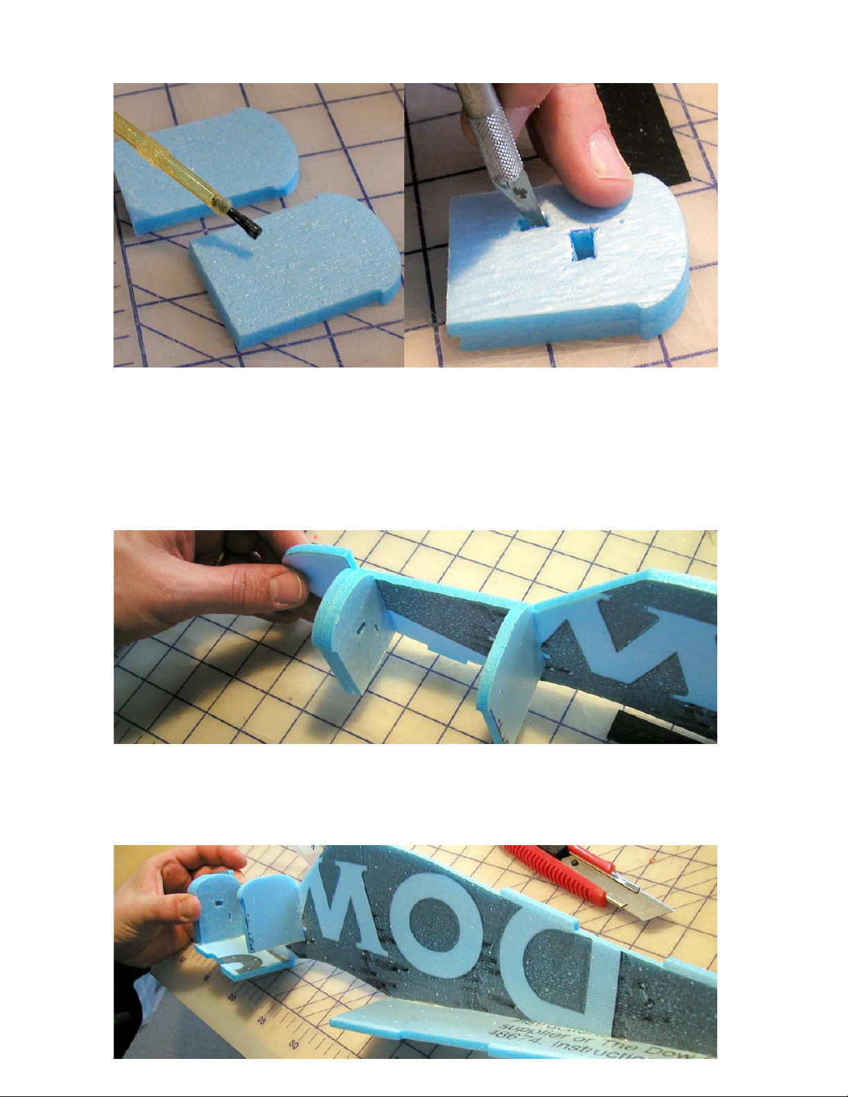
d) Peel the two Firewall formers and glue them to each other
Take a look at the two Firewall formers. Decide which face of each you’d
like to see, and peel the complete opposite side. Glue the two fuselage
formers back to back with their tops aligned.
e) Cut Holes in the Firewall formers as noted. (See the plans.)
f) You’ll need to make holes in the Firewall both for the motor stick, and
for the motor wires to pass through. If you’re unsure, smaller holes are
preferable, so the motor stick will be tight fit in the foam.
g) Glue the Firewall Formers, and the Hood Former to one half.
Glue both the Firewall & Hood Formers to one side of the fuselage. They
should align perpendicular to the hood line, with the ‘lip’ on the former
hooking on the top edge of the fuselage.
h) Glue the Fuse Bottom and the Fuse Front to that same half.
Grab your Fuselage Bottom piece, and glue it into the matching slots on the
fuselage half that you’ve been working on. Make sure you get glue on both
the faces and side of the tabs. Everywhere the foam will be in contact.
©2003 FoamFly.com 6
Page 7
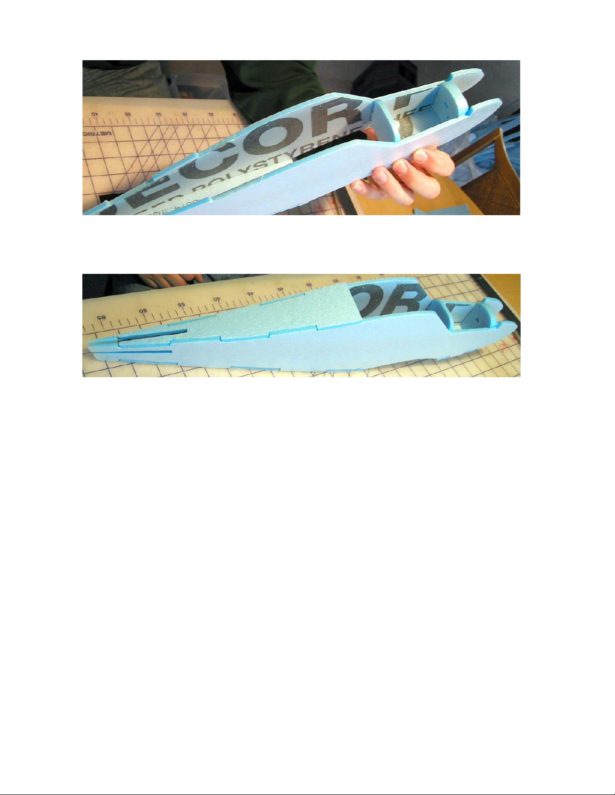
i) Glue the other Fuselage half in place.
Grab the other half of the fuselage, and glue it to the bottom, and the
formers all in one go. If you’re not using contact cement, you might need to
clamp it in place to hold the shape of the fuselage while the glue dries.
j) Glue the Fuselage Top in place.
Glue the top piece of the Fuselage into place, and you can definitely see a
plane taking shape now.
3) Motor Mount: 1 3/4” piece of 3/8” x 3/16” BassWood
a) Shave the motor stick to fit in the gearbox.
Using your knife or sandpaper, shave down one end of the motor stick until
it’s a good tight fit into the motor gearbox. Make sure that the stick fits all the
way into the gearbox. If you’re worried that the motor might pull itself off the
stick while in flight, you can put a few layers of Scotch tape onto the stick to
ensure that the gearbox is a tight fight.
b) Glue the motor stick into the Firewall with the thrust angle as noted.
Force the uncarved end of the stick into the foam, and position it to the
desired angle. You’ll want 2-3 degrees of right thrust, and about 1 degree of
down thrust relative to the firewall. It’s probably a good idea to glue the stick
in place with the motor on it (if you think you can avoid getting glue on the
motor) because the thrust angles really need to be relative to the prop shaft
more than the stick. Polyurethane glue, or foam safe CA work great for
gluing the stick into the foam. You can also use ordinary Elmer's glue as
well.
4) Tails:
It’s time to prepare the working surfaces of the Staggerwing. The tails give
the plane it’s directional stability, and let you do the steering.
a) Elevator:
i) Choose Top and bottom of Horizontal Stabilizer.
The foam has its own character, so you can flip a coin. (or an elevator)
and decide which side of the surface you’d like to have facing up.
©2003 FoamFly.com 7
Page 8
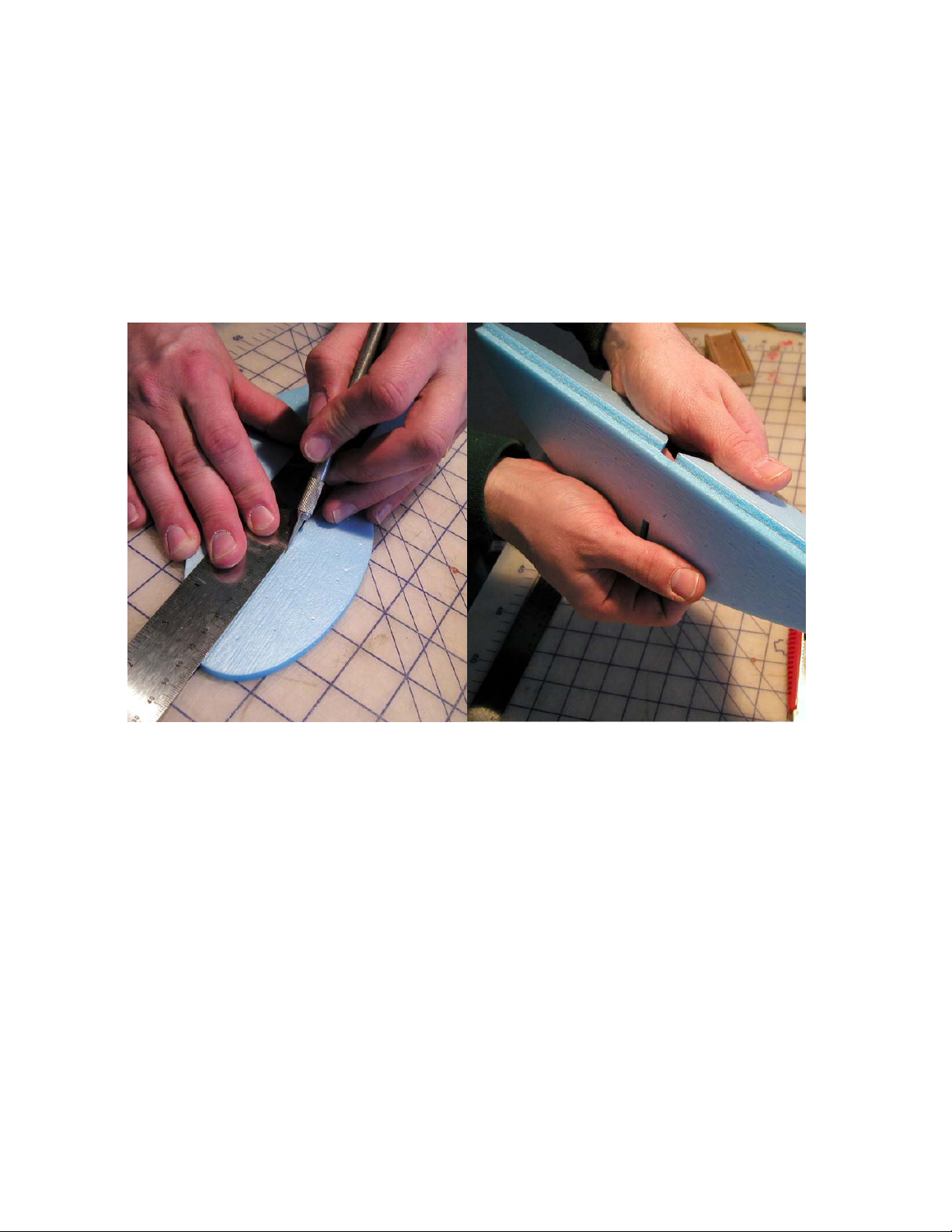
ii) Flip Horizontal Stabilizer Bottom side up
iii) Locate the hinge line
You’ll notice two small dimples in the outer edge of the elevator. If
you line up your ruler with the two dimples and the notch at the middle
of the elevator halves. You’ll have found the line you need to cut.
I prefer to use an, “integral skin hinge” for the elevator, but if you feel the
need, you can always cut the elevators off, and tape hinge them back in
place.
i) Integral Skin Hinge:
(1) Cut hinge line 80% through.
It’s important to cut the entire length of the hinge line at once
so that both halves of the elevator will line up with each other.
(2) Fold Elevator back 180˚
(3) Bevel each elevator half with Knife or Sanding Block
Be careful not to peel or cut the skin during this step. (See the
Appendix section, “Tapers and Angled cuts”)
©2003 FoamFly.com 8
Page 9
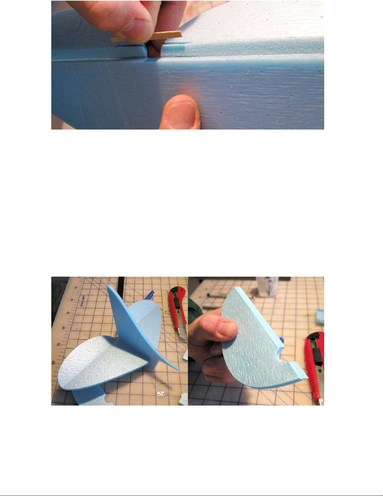
(4) Glue a 1.75” section of the wooden stick between the elevator
halves.
You’ll need to cut a small slot with your knife, for the stick to fit
into. Then, hold both elevator halves folded completely back,
or pressed flat on the table, while you glue the stick in place.
(This ensures that both halves will be straight.)
(5) Fit the Horizontal and Vertical Stabilizers together. (BEFORE
the rudder is attached!)
b) Rudder:
The Rudder is a little easier to do than the Elevator since it’s a separate
piece. There’s still some work you’ll need to do to it though.
i) Bevel the leading edge of the Rudder.
Cut a small 45˚ bevel on the front (straight) edge of the rudder, on
what will be the right hand side. (See the Appendix section,
“Tapers and Angled cuts”)
ii) Trial Fit the Rudder to ensure it clears the Elevator, and that both
surfaces will have free movement.
iii) Tape the Rudder. Carefully trim the tape out of the rudder cutout.
Run a strip of 2” wide packing tape along the hinge line of the
rudder piece. It should be half on, and half in empty space. Now
remove the tape where the elevator connector will go.
©2003 FoamFly.com 9
Page 10
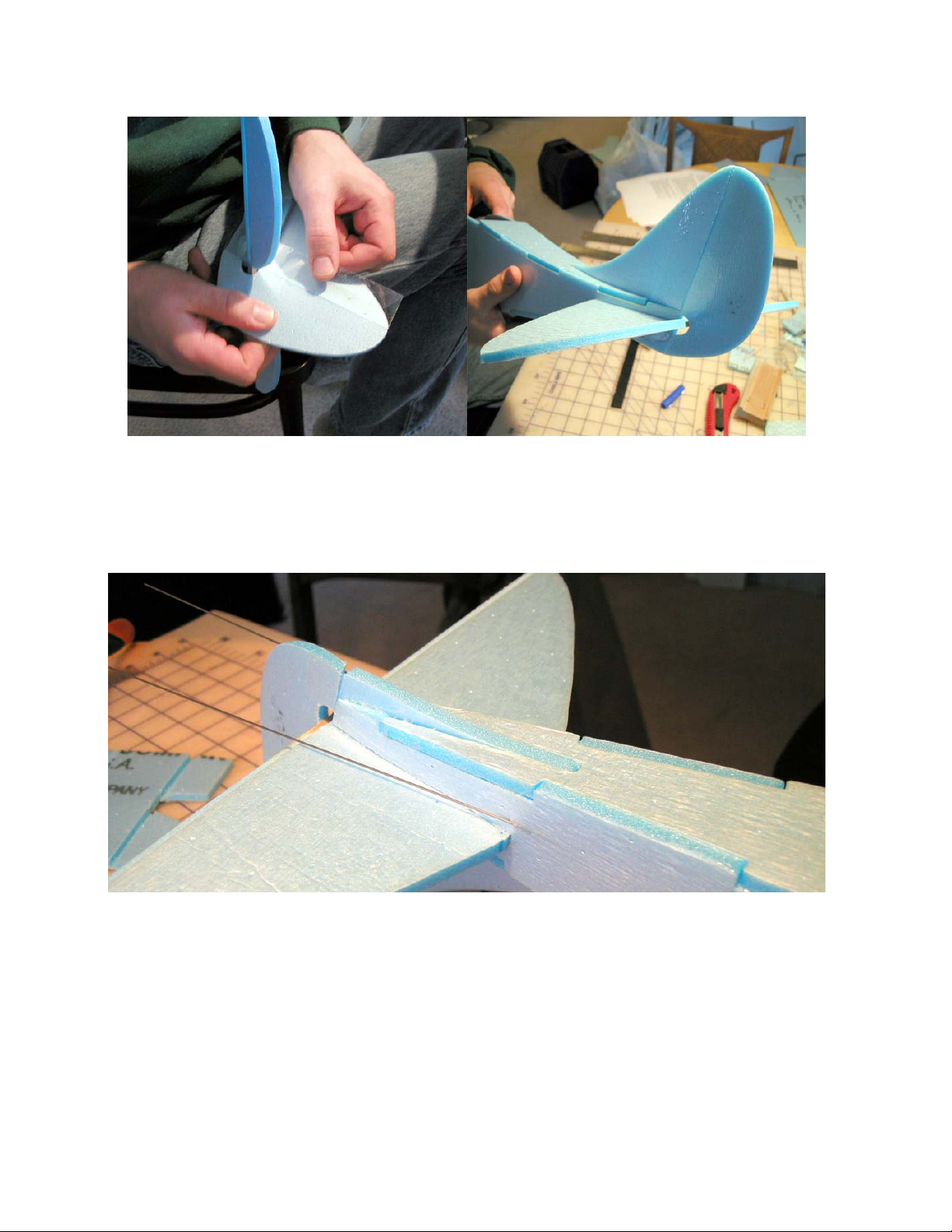
iv) Tape the Rudder in place, then trim the excess tape. Put the tip of
the rudder against the center of the Vertical Stabilizer and pushed
at full deflection while you smooth the tape onto the Vertical
Stabilizer.
v) Test fit the tails into the fuse, and then glue them in place
5) Radio Gear:
a) Install the lower Wing Saddle Doublers in the bottom wing opening.
You won’t need to peel anything here, just glue them inside the fuse so
that the curves line up exactly.
b) Twist the Pushrods into each side of the fuse.
c) Start at a point about 1/4” below the front end of the elevator slot, and
aim the wire so that they come out on the inside about 2” further ahead
of where they went in. You can also get the hole started with a long pin,
or sewing needle.
d) Work the pushrods back and forth so they slide freely. It’s important
that the control rods don’t bind while you’re flying.
e) Before sticking anything, it’s a good idea to power up, center the servo
arms, and put the little connectors into the servo arms.
f) Mount the servos in the position indicated on the diagram (See the
plans.) at the correct angle to line up with the pushrods. Put your
double sticky tape onto the servos first, and then, after double checking
to see where the servo will end up, peel the other half of the sticky tape,
and firmly press the servo into place.
©2003 FoamFly.com 10
Page 11
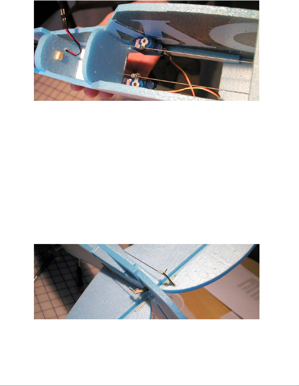
g) I recommend the Dubro Mini-EZ connectors:
They’re definitely the easiest way to attach the pushrods to the servos,
but if you can’t want to get some of them, the traditional way works fine.
Make a small Z-Bend in the end of each pushrod. These will lock into
the control horns. Near the Servo end, make a V bend about 3/8” tall.
Once you’ve figured out how long the pushrods need to be, you can
make a similar Z-Bend at the other end, and cut off the excess. You’ll
need to remove the servo arms from the servo to get them over the ZBend. You can use the V to make slight adjustments to the length of
the pushrods.
h) Mount the Receiver to the Hood Former inside the Radio compartment
using double sticky tape.
i) Glue the Control Horns into the Surfaces. The Rudder Control Horn
goes on the right hand side of the Rudder, far enough below the
Elevator that it won’t interfere with control surface movement. The
Elevator Control Horn goes on the underside of the Elevator, on the left
hand side of the Fuselage. Make small cuts with your X-Acto knife
where the control horns will line up with the pushrods, and test fit the
control horns in place. Now glue them in, with a little Epoxy, or foam
safe CA. Make sure the holes are lined up directly over the hinge line.
I really like these control horns. They’re designed specifically for foam,
as they put a much larger surface area into the foam for glue to hang
onto. I’ve had them laser cut in two sizes for use on a variety of
airplanes. If you’d like to get more of them to use in your own projects,
they’re available at the FoamFly.com Store in the Accessories section.
©2003 FoamFly.com 11
Page 12
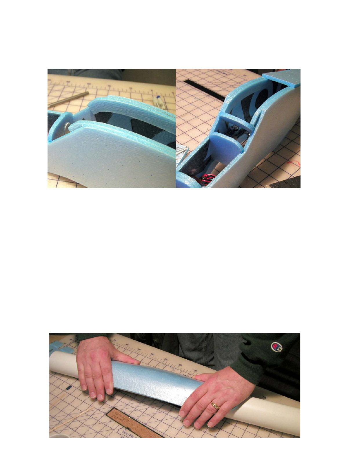
6) Top Formers:
a) Glue in the Top Wing Saddle Doublers with the indicated overlap. (See
the plans) This is a little tricky. These pieces are SUPPOSED to stick
out in front. The amount sticking out should be one thickness of the
foam, and the curve on the top surface should line up exactly. Kit
builders will notice that there are little dimples cut into the top of both the
Top Wing Saddle Doublers, and the Fuselage sides. If you line these
up, you’ll have an easy time.
b) Glue in Windshield Former flush with Doublers (See photo, and
Fuselage Diagram) This piece goes in at an odd angle. No peeling is
necessary, but the former should be glued to both the sides of the
fuselage, and the end of the doublers.
7) Wings:
a) Decide which side will be the top of the wings. The foam usually has a
lumpier side, and a smoother side. I prefer to have the smoother side
on the top of my wings, but it doesn’t matter much as long as all four
wings end up the same.
b) Make sure you end up with 2 LEFT and 2 RIGHT!!! This is
EXTREMELY important. All the wing pieces are essentially identical
until you form the airfoil into them. So watch out, a plane with three left
wings doesn’t fly too well.
c) Roll the wings into shape: Now that you know which side is up for your
wings, roll the airfoil shape into them. (See the Appendix Section,
“Rolling the Foam”)
©2003 FoamFly.com 12
Page 13
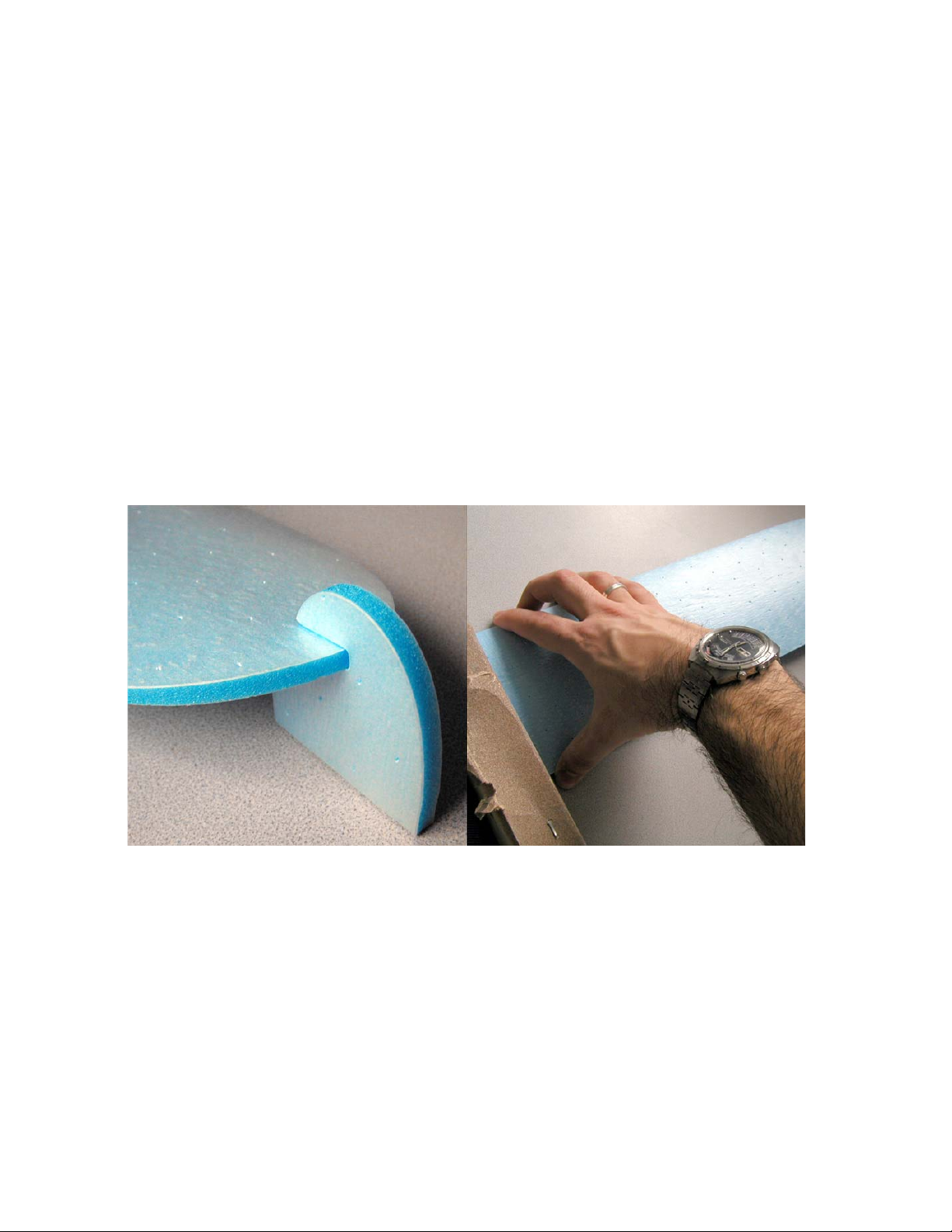
Now the wing pieces probably have more curve than they need. Grab
one of the parts with the airfoil shape, (Like the struts, or the landing
gear mounts, although the fuselage will do too.) and use it to check your
airfoil. If it’s not an exact fit, massage the wing a little until it’s pretty
close. The glue will do the rest.
(Note: If you have the FoamFly.com Wing Jig, you can bake wings for
this plane using the same standard airfoil. The Staggerwing uses a
subsection of the Frog Airfoil. You would cut 1” off the leading edge of a
baked panel, and 1.5” off the trailing edge to make your 4.5” chord
wings.)
d) Use the foam Dihedral Jig to sand the required 5˚ dihedral into each
wing. Clip the tool onto the tip of the wing that you’re working on, and
then cut or sand the root of the wing exactly vertical. You can do this
easily by holding you sanding block against the edge of your kitchen
counter, and then pressing the wing end against it. (I would recommend
that you slide the wing back and forth, and not the sanding block. It’ll
help protect your counters, and maybe your marriage.) Be sure to keep
the wing in it’s finished airfoil shape while you’re sanding. If you like,
you can slip on of the foam landing gear mounts under the wing about
2” from the root, and press down on it to hold the airfoil shape while
sanding.
e) Glue the wing halves together. If you’re using contact cement, you can
just wait until the glue is dry but still tacky (about 10 minutes) and then
press the wings halve firmly together. If you’re using Epoxy, or another
slower setting glue, leave the Dihedral Jigs clipped on the wingtips to
hold the wings at the correct angle while the glue dries.
f) Identify the Wing Struts (The kit parts are marked with a small ‘L’ and ‘R’
for the Left and Right Struts. They have a 5˚ angle cut into them so
they’ll sit flat on the wings after the dihedral has been sanded in.)
©2003 FoamFly.com 13
Page 14
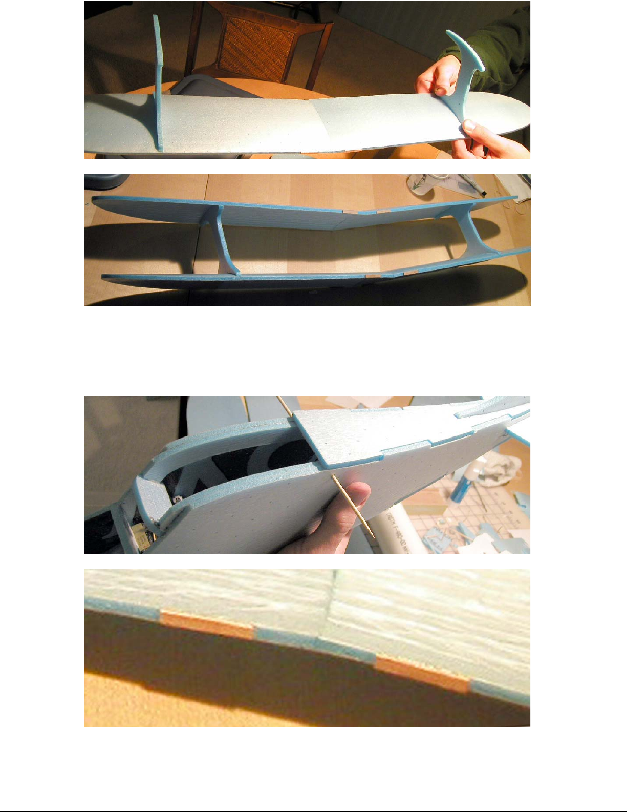
g) Glue the Wing Struts to the bottom wing 9” from the center.
h) When dry, Glue the upper wing to the struts so they are the same 9”
from center.
8) Wing Mounts:
a) Skewer the Fuselage as indicated on the fuselage diagram. (See
Appendix)
b) Cut eight 3/4” pieces of the wood strips,
c) Glue them to the front and rear of the upper and lower wings where the
rubberbands will cross the wings. Press them in until they are almost
flush with the leading edge of the wing, or you might need to sand the
fuselage a little to make the wings fit on.
©2003 FoamFly.com 14
Page 15
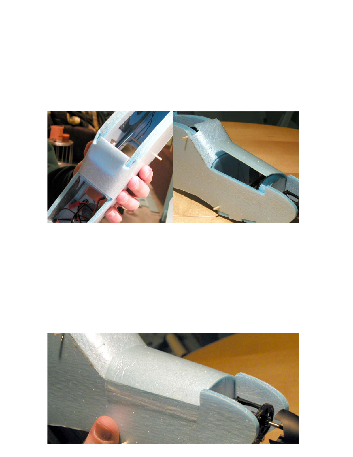
9) Hood & Windshield:
a) The Hood and Windshield parts should be shaved, sanded, or carved to
half the foam’s usual thickness.
b) Roll The Hood gently over a broom handle or similar sized item.
c) Roll the outer edges of the windshield back over a pen or a wood dowel.
Roll the top “wrapover” portion of the windshield back.
d) Test fit the Windshield. It is slightly oversized, and may require a little
sanding or trimming to be a good fit.
e) Sand bevels on the back of each like this: On the Windshield, the outer
sides where it meets the fuselage need to be beveled. On the Hood,
the outer sides, and the end that meets the Windshield need a bevel.
(These small bevels are most easily done with sandpaper.)
f) Glue the Windshield into place.
g) Trim the outer top edges of the Windshield until they are even with the
Top Wing Saddle Doublers.
h) Tape Hinge the hood into place. Use a piece of Packing Tape, or
Crystal Clear Scotch Tape, to hinge the hood on one side.
i) Wrap Tape over the opposite side of both the hood and the fuselage.
This will create a protective surface (tape doesn’t stick to tape right?)
j) Add a tape tab to that side to hold the lid closed in flight. Fold about 1/8”
over along a piece of scotch tape. Cut it to the length of one side of the
hood, and stick it with the tab hanging out onto the protective tape on
the edge of the hood. You can now press the remaining tape down onto
the protective surface on the fuselage to hold the door closed. (If the
tape begins to lose it’s stickyness, you can carefully peel it off the hood,
and replace it. One piece lasts a long time.)
©2003 FoamFly.com 15
Page 16
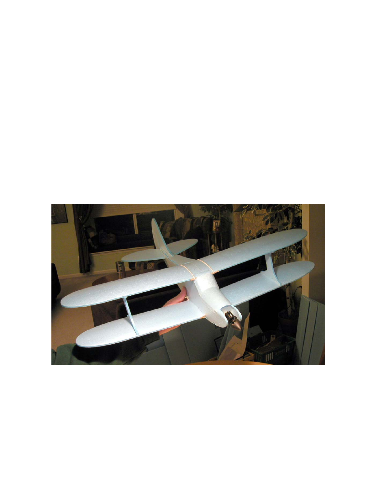
k) Position the battery inside the compartment as needed to achieve the
CG.
l) Now you can roll down the tabs on either side of the motor to match the
curve of the hood for a finished appearance.
10) Control Throws and Balance:
a) Throws.
i) Elevator: 1.25” maximum in either direction (about 30˚)
ii) Rudder: 1.25” maximum in either direction (about 40˚)
If you’re a beginner, you might want to start with smaller movements
than these, but eventually you’ll want to work your way to these settings.
b) CG: 1/2” behind the leading edge of the upper wing.
The Staggerwing has a fairly forgiving CG range, but it’s always safer to
start out a little noseheavy, and then adjust things backwards as
needed. Remember, “A noseheavy plane flies poorly. A tailheavy
plane flies once.” If you’ve used all the recommended equipment, and
haven’t put the entire bottle of glue on the plane, you should balance out
with no trouble. Re-position the battery under the hood as necessary.
You’re Done!
Carefully rubberband the wings in place (Criss-Cross works best) and you’re
ready to fly.
©2003 FoamFly.com 16
Page 17
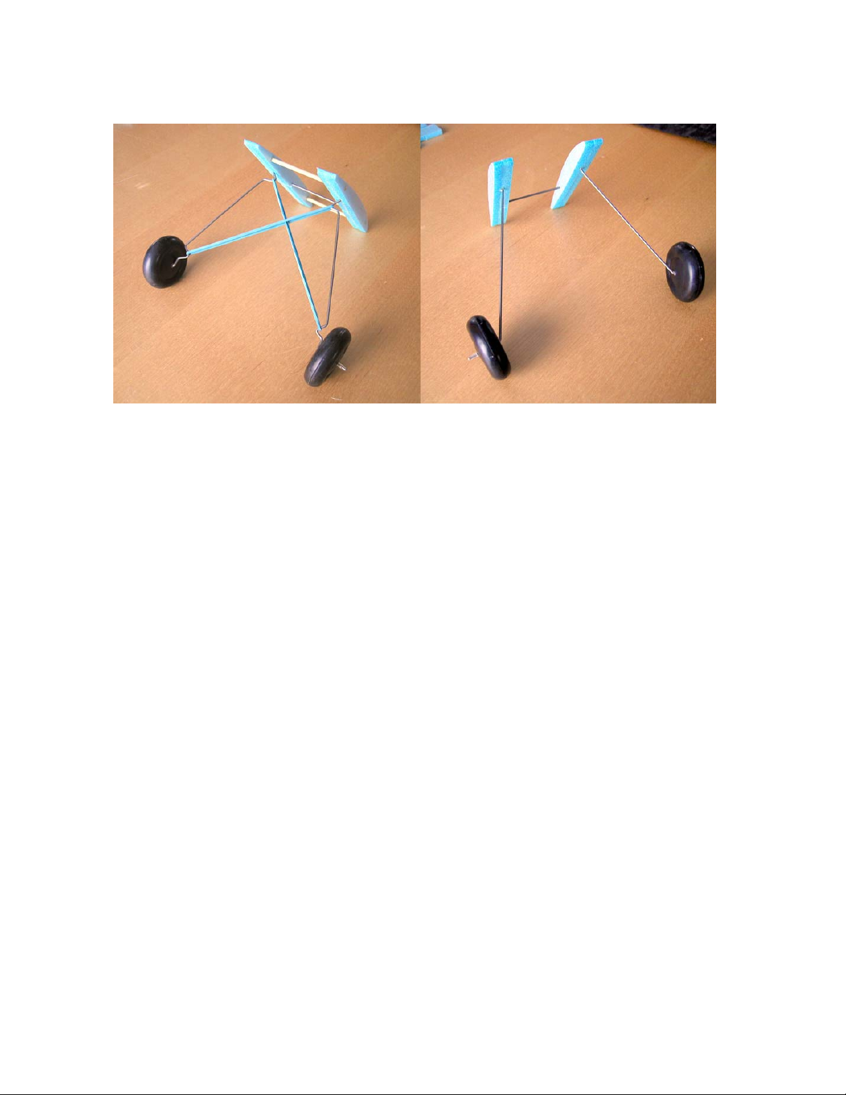
11) Main Landing Gear (Optional)
a) How good a wire bender are you? Decide which version of the gear
you’d like to bend. The Suspension version is neater, but harder to
bend. The “traditional” landing gear has only 8 bends, so that may be
the way to go. (The Templates are on the plans.)
b) 1.5” wheels are recommended. I like the Dubro Mini Lite Wheels, but
have also had good results with Guillow’s free flight wheels too. If you
want to use larger wheels, just remember to shorten the wire
accordingly. (Subtract half the additional diameter from the length. If
you use 2.5” wheels, which are 1” larger, then subtract 1/2” from the
length etc.)
c) Decide whether you’d like to do Taildragger, or Tricycle gear. I think the
Tricycle gear is cute, and it does protect you from noseovers, but mean
more wire to bend, and you’ll need another wheel too.
d) Get bent.
Use a pair if pliers to bend the landing gear to match the included
template. I find it easiest to hold the wire up to the template, and mark
the location of the next bend, so that I can pickup the wire and work on
it.
e) Toe-In helps ground handling. After you’ve so carefully bent the gear to
match the template, you’ll need to bend it out of shape. What? Well,
having the wheels point very slightly towards each other as the plane
moves forward makes taxiing a lot easier, and bending the gear so that
the wheels are a little closer to each other will give the landing gear
some springiness to help it support the weight of the plane. Of course
you only do this to the main gear, the nosewheel should be straight.
©2003 FoamFly.com 17
Page 18
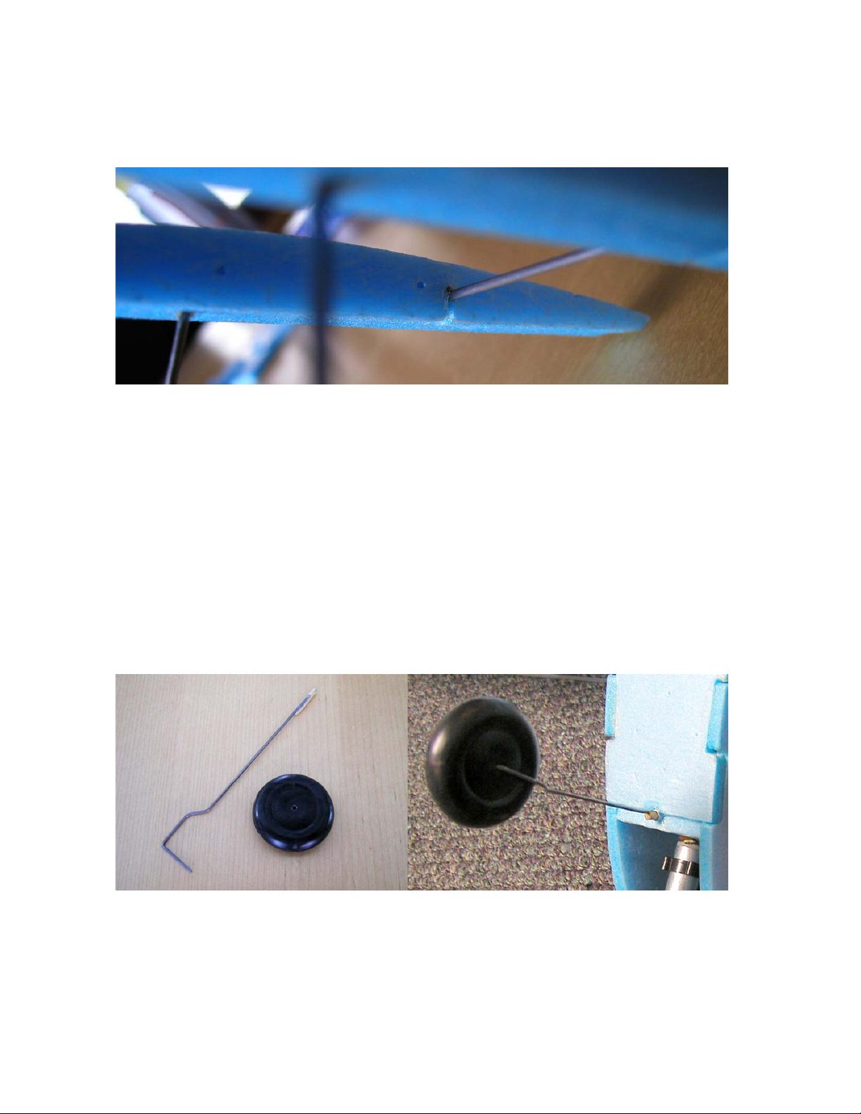
f) Foam Landing Gear Mounts:
i) Position the wire gear for your setup.
For tail draggers, the gear should be 1” from the front of the foam
mounts, with the bent over section pointing back, and the wheels
pointing forward.
For tricycle gear setups, the gear should be 1.5” from the back of the
foam mounts, with the bent over section pointing forward, and the
wheels pointing back.
ii) Cut a 1/8” slit in two of the foam piece where the cross bar will be.
iii) Peel the facing surfaces of the foam parts. Two on each side
iv) Press the landing gear wire into the soft foam as a trial fit.
v) Glue each side in place, making sure that the foam mounts are
parallel with each other.
vi) Optional: Bamboo skewers will help to stiffen the landing gear
mount.
vii) The Main Gear is held in place by the criss-cross rubberbands that
hold the lower wing in place.
g) For Tail Draggers, a small piece of the wood strips, or the Bamboo
makes a good tailskid.
12) NoseWheel: (Even More Optional)
a) 5/32” aluminum Tubing
b) Bamboo Skewer or 1/8” dowel (Bamboo preferred)
c) Twist the Bamboo into the space between the two Firewall Formers.
d) Cut Aluminum Tubing to length, and pinch one end with pliers
e) Stick the Bamboo into the Tubing, and glue the tubing up into the
Firewall. Make sure it is in straight. Pull the Bamboo out, and leave the
tubing in place.
f) Drill a 1/16 hole through the middle of the Bamboo.
©2003 FoamFly.com 18
Page 19
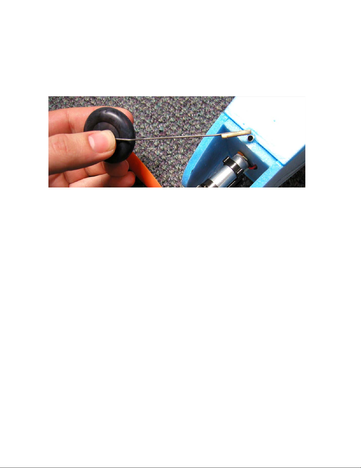
g) Cut/Gouge/Sand out a groove along the length of the Bamboo next to
the hole. In one direction.
h) Test fit the wire to ensure that it fits into the groove.
i) Cut the Bamboo to the length shown, and slightly taper the non-grooved
end.
j) Point the bend at the end of the wire through the hole, and run the wire
down the length of the groove.
k) Sand the wire to that the point doesn’t stick out past the Bamboo.
l) Test to see of the combo is a tight fit in the Aluminum tubing.
m) If all is well, glue the wire into the Bamboo.
n)
o) That’s it. Fit the wheel on to the axle, and insert the entire mechanism
into the tubing whenever you want to use landing gear. The Nosewheel
gear should be a tight fit in the tubing. Make sure the wheel is pointing
the right direction when you install the gear each time.
You’re still reading? Go fly already. ;)
Enjoy your Staggerwing. Share photos if you can, and don’t hesitate to get in
touch if you have questions, or need help setting up your plane.
Sincerely,
-Dan
[email protected]
©2003 FoamFly.com 19
Page 20

APPENDIX:
The Tools: (and things you’ll need)
1) Knives: a Razor knife, and an X-Acto would both be useful.
2) Glue: 3M “Insulation 78” contact cement, or Foam-Safe CA, or Elmer’s
White glue, or RC-56 type white glue, or Epoxy. You’ll probably want a
couple of these for good measure.
3) Tape: You’ll want 2” wide clear packing tape, and also some “crystal clear”
Scotch Tape if you can find it. If not, you can cut down the packing tape.
4) Sandpaper. Any Medium grit should do fine.
5) Pliers: Something suitable for wire bending.
The Techniques: You’ll probably want to practice these on a piece of the scrap
foam.
1) “Cut & Peel”
In certain areas you’ll need to peel some of the skin from the blue foam
to ensure that you get a good solid glue joint. If you don’t do this, everything
will be fine, but in case of an “impact” the skin could peel away, and you’d
have to glue it back in place (A real pain.)
Here’s how you do it. Use a SHARP razorblade, or X-Acto knife, and
run it lightly across the foam so that the tip just pierces the skin. Then, when
you’ve finished, stick the knife/razor point (or your fingernail) just under the
edge of the skin, and lift up one corner. Now carefully peel back the skin.
Do it slowly, the skin can tear when the peel reaches the little holes. It won’t
tear if you pull with small tugs held close to the foam. If you practice this will
make a lot more sense.
2) “Tapers & Angled Cuts”
a) It's almost impossible to cut a straight line freehand. So, what's your
number one tool for angled cuts? Your kitchen counter. Why not?
Formica is everybody's first choice for making hotwire templates, and
it’s tough, so use it where you find it. Lay your foam on the counter with
the end of the foam flush exactly at the edge of the counter. To
accurately control the angle of the cut, position your metal ruler on top
of the foam. If you place the straightedge directly above the counter’s
edge, you get a perfectly straight cut. If you slide the ruler back from
the edge, you get a perfect angled cut. Just make sure to get your
fingers out of the way as the hot wire or knife comes by.
b) Your other option gives you a little more time while you’re working.
Simply Cut & Peel the area where the bevel is going to be, and then
using a medium sandpaper like 200, or 250, carefully sand away the
bare foam until you have a smooth angle.
©2003 FoamFly.com 20
Page 21

3) “Glue” (Working with the contact cement)
a) “Basic Gluing”
The contact cement will test your patience. I know you’ll be
tempted to stick the pieces together immediately, but don’t be give in.
The 3M-78 will form the strongest bond, if you allow it to dry for AT
LEAST 8 minutes before putting the pieces together, and probably
much longer. Put the glue on BOTH surfaces to be joined. If you’re not
used to contact cement, remember you really only get ONE CHANCE at
putting the pieces together. It really is instant gluing! (except for the
waiting, but that’s already over at that point)
b) “Advanced Gluing”
The 3M-78 is ideally a spray glue, and there are some instances
where you can actually spray it during this project. You’ll want to make
sure that you carefully mask off any areas where you don’t want the
glue. You can do this by cutting custom shaped glue shields out of
paper, or masking tape. Be sure to test your masking tape on the scrap
foam to make sure that it doesn’t peel the skin off when you remove it.
For the rest of the areas (Like attaching the wings) you’ll want to
brush the glue on. Just spray some on some waxed paper, and use a
scrap of foam, or a disposable brush to paint it right on both surfaces to
be glued.
The 3M-78 has a long working time. After application, the glue can
sit for over half an hour and still make a full-strength bond. If you plan
ahead a little, you can apply the glue to all the fuselage surfaces in the
order that you’ll be assembling them, and the first ones will be ready to
press together by the time that you’re done applying glue to the least.
Then proceed in order, for an exceptionally quick build.
4) “Rolling the Foam”
You’ll be bending the foam to form the airfoil for the wings. You’ll also
need to bend the windshield and Hood parts to conform to their curves.
You need to get a feel for how much pressure the foam will take before
it gives.
a) Wings: Find yourself a section of 2” PVC pipe, (Or a BaseBall Bat,
Rolling Pin, Kitchen Counter, Bathtub edge, etc…) and press the wings
firmly and evenly down onto it to form the airfoil shape. It doesn’t take
too much pressure. The airfoil curves more sharply right near the
leading edge, so you can use smaller diameter pipe (or a Broomhandle
etc.) to add a little more curvature there if you feel it’s necessary. It’s
also acceptable to just use your thumb, and the side of your index finger
to work the leading edge bend a little.
b) Other Parts: Small parts that need rolling can be rolled over a pen, or an
X-Acto knife handle etc. These items generally take very little effort to
bend, but should still be formed over a solid object to avoid wrinkles.
©2003 FoamFly.com 21
 Loading...