

Page 1
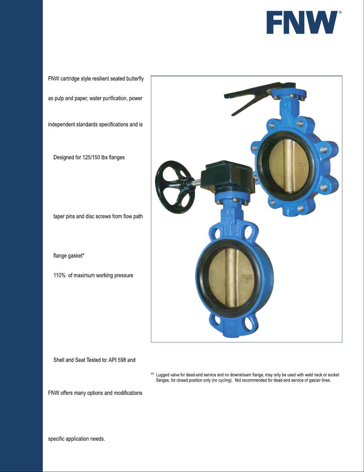
Figure 711 & 712
BUTTERFLY VALVES
RESILIENT SEATED BUTTERFLY VALVE
valves are designed to meet the rigorous
requirements of industrial applications such
and utilities, chemical/petrochemical, food
and beverage, OEM and HVAC. Each
valve is manufactured in accordance with
100% tested in both directions of operation to
assure bubble-tight service for many years.
Features:
•
• Standard aluminum-bronze disc
• Mounting pad with square shaft permits
direct mount actuation that reduces
hysteresis and cost (2" TO 12")
• Secured stem retainer plate for blowout-
proof protection and also allows operator
removal with valve in line
• High strength two-piece stem eliminates
• Rated to 200 PSI (2"-12"), 150 PSI
(14"- 24")
• Cartridge style seat permits easy change
without special tools
• Molded o-ring eliminates the need for
Lockable Handles (up to 8")
•
• Shell tested to 150% and seat tested to
• Lug bodies for dead-end service rated at
150 PSI** (2"-12"), 100 PSI** (14"-24")
• Dual PTFE shaft bearings for reduced
torque and improved stem alignment
• Vacuum rated to 29.9196"Hg (0.01 Torr)†
• Epoxy coated body
• Low maintenance design
Standards:
• NSF 61 Annex G Certified
(Annex G references NSF 372)
• Design: API 609A and MSS SP-67
•
MSS SP-61
• Top Flange to: ISO 5211
Options:
for valves. These include, but are not
limited to: Actuation including chain wheels,
square drive nuts, worm-gear operators, and
pneumatic and electric operators, control
accessories, stem extensions, and custom
mounting hardware. Contact FNW with your
Fig. 712
Fig. 711
* Pressed collar style angle face rings (typically sizes 2" to 6") are not recommended due to the large radius
of the inner diameter. Cast type angle face rings or stub ends should be used with light wall stainless steel
piping. Prior to installation, always verify that the connecting piping flange face fully engages the valve
seat face.
† Vacuum measurements are often made in inches of mercury below atmospheric pressure. The values
calculated here assume standard atmospheric pressure of 29.92 inches of mercury.
FNW.COM
Page 2
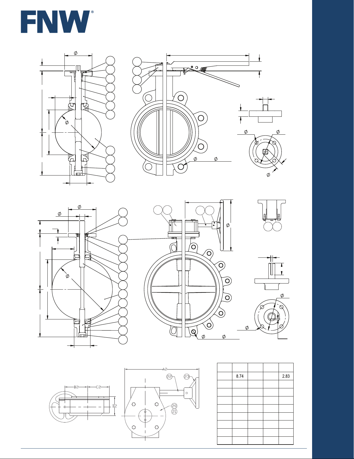
711 / 712 - Sizes 2" to 12" (10" & 12" standard with gears)
U
H3
H2
H1
B
A
2
1
3
4
6
5
7
D
8
9
4
L1
10
16
15
14
13
WAFER
Figure 711 & 712
BUTTERFLY VALVES
L2
H4
T
P
4x
LUG
HxN on
S
C b.c.
TOPWORKS
Q
V
711 / 712 - Sizes 14" to 24"
H3
H2
H1
B
P
U
T
A
D
L1
1
3
24
2
4
4A
7
6
8
9
5
4
4B
10
20 21
WAFER
Additional Gear Operator Dimensions for 6" to 24" Valves*
(Gears for 10" & up are standard)
* Gear operators are available for 2" to 5"
valves upon request.
G2
22 23
HxN on
LUG
G1
4 x
C b.c.
W1
S
TOPWORKS
12 11
18"~24"
BOTTOM
ASSEMBLY
X
W2
Dimensions (inches)
Size A2 B2 C2 D2
6" 1.77 2.13
8"
10.51 2.60 2.99 3.31
10" 10.51 2.60 2.99 3.31
12" 10.51 2.60 2.99 3.31
14" 13.62 3.05 3.09 3.49
16" 13.62 3.05 3.09 3.49
18"
13.62 3.05 3.09 3.49
20" 17.32 5.31 5.12 4.33
24" 17.32 5.31 5.12 4.33
Q
Phone: 503-287-8383 ~ Fax: 503-281-9677 ~ www.FNW.com
2
2
Phone: 503-287-8383 ~ Fax: 503-281-9677 ~ www.FNW.com
Page 3

Figure 711 & 712
BUTTERFLY VALVES
Dimensions (Inches) Sizes 2 to 12
Size A B ØD H1
2"
2-1/2" 0.41 2.52 2.64 2.95 5.36 5.20 1.06
3" 0.67 3.03 3.15 3.67 5.64 6.07 1.06
4" 0.94
5" 1.36
6"
8"
10" 3.52 9.62 9.72 11.13 10.50 14.25 12 4.92 0.79 4.02 0.43 1.00
12"
Size A B ØD H1 H2 G1 G2 L1 ØC ØH N H3 ØU P ØQ ØS ØT W1 W2 X
14" 4.96
16" 5.45
18"
20" 7.15 19.13 19.29 14.96 17.32 15.55 10.12 5.00 25.00
24"
1.93 2.05 2.77 5.06 4.94 1.06 1.69 11.37 4.75 4 0.60 3.54 0.55 2.76 0.35 0.43 0.55
3.94 6.41 6.54 1.06 2.05 11.37 7.50 0.70 3.54 0.63 2.76 0.35 0.55 0.63
4.92 4.69 7.34 7.13 1.06 2.20 11.37 0.70 3.54 0.63 2.76 0.35 0.55 0.71
5.93 1.06 2.20 11.37 5.79 6.22 9.51 0.70 3.54 0.63 2.76 0.35 0.55 0.71
2.69 7.62 7.74 6.51 9.34 9.26 1.06 2.36
11.54 11.63 9.47 12.27 12.15 3.07 17.00 12 0.95 4.92 0.79 4.02 0.79 1.10
12.99 10.41 13.60 3.07 12 4.92 0.79 4.02 0.47 1.10 0.39 0.20 2.36
14.92 11.75 13.76 4.02 21.25 16 3.15 0.91 5.51 0.71 1.26 0.39 0.20 2.36
6.36 17.09 17.20
22.46 22.62 17.32 15.55 10.12 6.06 29.50 20 3.74 0.91 6.50 2.17 0.55 0.20 2.76
H2
731 732
H4 L1 L2 G1 G2 ØC ØH N H3 ØU P ØQ ØS T ØV
11.37 5.49 4 0.60 3.54 0.55 2.76 0.35 0.43 0.55
11.37 6.00 4 0.60 3.54 0.55 2.76 0.35 0.43 0.55
11.75 3.54 0.67 2.76 0.35 0.67
Dimensions (Inches) Sizes 14 to 24
15.75 15.55 4.49 22.75 16 3.15 0.91 5.51 0.71 1.50 0.47 0.20 2.36
20 3.54 0.91 6.50 1.77 0.47 0.20 2.76
Standard Materials
Ref. No. Description Material Qty Remarks
1 Retaining Plate
2 Retaining Plate Screw
3 Ingress Stem Seal SAME AS SEAT MATERIAL 1
4 Stem Bushing PTFE
4A Upper Hard Bushing 1
4B Lower Hard Bushing 1
5 Body
6 Upper Stem 416SS STAINLESS STEEL 1
7 Seat EPDM or BUNA 1
Disc 1
9 Lower Stem 416SS STAINLESS STEEL 1
10 Plug
11 Bottom Plate 1
12 Bottom Plate Screw 4
13 Lever Stop Plate 1
14 Lever ASTM A47 Gr 32510 MALLEABLE IRON 1
15 Lever Washer 1
16 Lever Bolt 1
20 Gear Housing ASTM A126 CAST IRON 1
21 Gear Drive ASTM A536 65-45-12 DUCTILE IRON 1
22 Gear Input Shaft STEEL 1
23 Hand Wheel ASTM A126 CAST IRON 1
24 Gear Mounting Bolt 4
Standard configurations are with levers up to 8" and gear operators 6" to 24". Gear operators for valves 5" and smaller are available upon request.
ASTM A126 CAST IRON
ASTM A536 65-45-12 DUCTILE IRON
1 Galvanized
2
Galvanized
3
2
4
1
1
Phone: 503-287-8383 ~ Fax: 503-281-9677 ~ www.FNW.com
Phone: 503-287-8383 ~ Fax: 503-281-9677 ~ www.FNW.com
3
3
Page 4

Figure 711 & 712
BUTTERFLY VALVES
Weight (Lbs)
SIZE WAFER / LEVER WAFER / GEAR LUG / LEVER LUG / GEAR
2" 7.8 - 8.0 -
2-1/2" 8.8 - 9.9 -
3" 9.4 - 10.3 -
4" 10.8 - 15.3 -
5" 15.2 - 19.4 -
6" 18.4 26.6 21.5 29.7
8" 27.3 42.9 36.1 51.7
10" - 61.1 - 74.8
12" - 82.0 - 103.0
14" - 107.6 - 146.2
16" - 161.8 - 196.0
18" - 202.0 - 268.3
20" - 305.1 - 367.8
24" - 472.1 - 522.6
SIZE
" 8 9 18 28 55 72 110 135
2
2-1/2
" 10 15 27 44 85 110 168 210
3
" 15 23 39 65 130 165 250 310
4
" 27 41 71 115 230 300 465 540
5
" 58 86 150 245 480 610 980 1,100
" 96 140 245 400 785 1,010 1,615 1,910
6
8
" 165 245 410 685 1,275 1,715 2,670 3,185
" 255 380 650 1,130 2,100 2,700 4,250 4,900
10
" 370 540 950 1,570 3,050 3,950 5,950 7,350
12
14
" 450 750 1,300 2,210 4,080 5,610 8,078 11,200
" 640 900 1,720 2,790 5,000 7,650 10,770 12,900
16
" 730 1,250 2,295 3,700 7,050 9,180 13,900 17,500
18
20
" 910 1,595 2,850 4,630 8,600 11,500 17,540 22,400
" 1,250 2,290 4,000 6,090 12,500 16,500 23,590 28,300
24
20° 30° 40° 50° 60° 70° 80° 90°
DEGREES of DISC OPENING
Torque (In-Lbs)
Size EPDM & BUNA Seat
2
" 324
" 324
2-1/2
" 424
3
4
" 524
5
" 574
" 858
6
8
" 1,677
" 3,543
10
12
" 4,092
" 10,296
14
16
" 13,466
" 18,109
18
20
" 22,366
" 36,036
24
1. All unseating torques based
on non-corrosive clean, wet or
lubricating service at ambient
temperatures. Contact FNW for
2. For line velocities greater than
15 FPS, dynamic torque must be
taken into consideration.
3. All torques are based on
maximum pressure differential for
the valve.
Torque values shown are
4.
reflective of a 30% safety factor.
Cv is the volume of water in U.S. gallons per minute that passes through the valve at a pressure drop of 1 PSI at 68°F.
Figure Number Matrix
F N W 7 1 1 E G X
BODY TYPE SEAT OPERATOR SIZE CODES
12==Wafer
LugEB==
EPDM
BUNA-N
BlankG==10 Position Lever
(2"-8")
Gear Operator
(6"-24")
2-1/2
2
=
K
10
=
L
12
3
=
M
14
4
=
P
16
5
=
S
18
6
=
U
20
8
=
X
24
=
10
=
12
=
14
=
16
=
18
=
20
=
24
Seat Temperatures
Seat Material Working Temperature
EPDM
Buna-N
-22° to 230°F
(-30°C to 110°C)
-4° to 194°F
(-20°C to 90°C)
DOC: FNW711-712V10 Ver. 1218 1074762
© 2018 - FNW. All rights reserved.
The FNW logo is a trademark of Ferguson Enterprises, Inc., PL Sourcing, PO Box 2778, Newport News, VA 23609
The contents of this publication are presented for information purposes only, and while effort has been made to ensure their accuracy, they are not to be construed as
warranties or guarantees, expressed or implied, regarding the products or services described herein or their use or applicability. All sales are governed by our terms and
 Loading...