

Page 1
147
Visit us at www.fnw.com
Figure 721
THERMOPLASTIC VALVES
WAFER STYLE BUTTERFLY VALVE
Features
• Compact Design
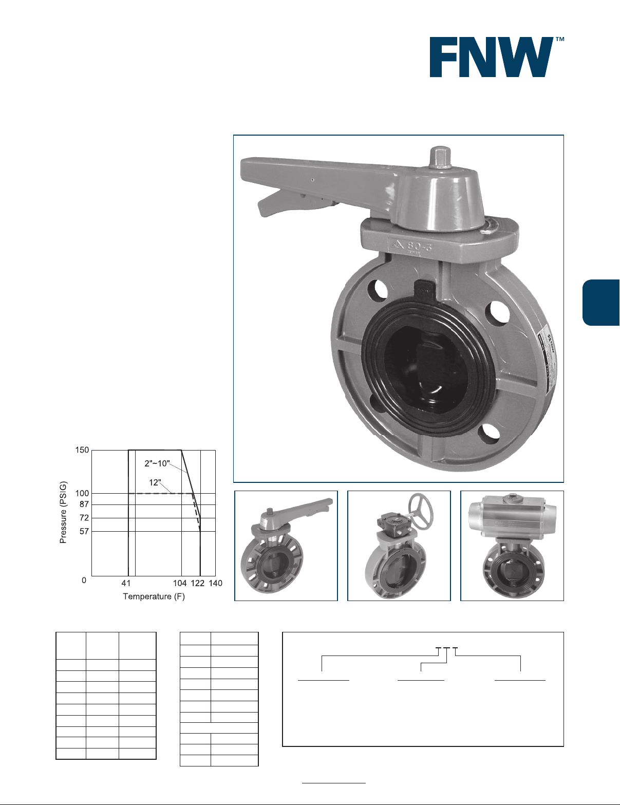
• Pressure Rating:
○ 150 PSI (2" to 10")
○ 100 PSI (12")
• Temperature Range: 41°F to 122°F
(5°C to 50°C)
• EPDM or FPM (Viton®) Seat/Seals
• Wafer Style with Guide Holes Drill to
125/150# Flanges
• Bubble Tight Shut Off
• Ideally Suited for Limited Piping Spaces
• Can Be Modifi ed for Actuator Installation
• Lever Operated (2" to 8")
• Gear Operated (8" to 12")
Options
FNW offers many options and modifi cations
for valves. These include, but are not limited
to: Actuation including chain wheels, worm
gear operators, pneumatic and electric
operators, control accessories, stem
extensions, and custom mounting hardware.
Contact FNW with your specifi c application
needs.
Cv & Torque
Size Cv
Torque
(in-lbs)
2 100 107
2-1/2 265 185
3 390 248
4 500 460
5 660 735
6 1160 825
8 1995 1,042
10 3570 2,400
12 5048 3,400
Pressure/Temperature
F N W 7 2 1 E G X
SEAT/SEALS OPERATOR SIZE CODES
EV==EPDM
FPM (VITON®)
BLANKG==LEVER (2"~8")
GEAR (8"~12")22-1/2
3
4
5
=
=
=
=
=
K
L
M
P
S
6
8
10
12
=
=
=
=
U
X
10
12
Figure Number MatrixWeights
Size Wt. (Lbs.)
2 2.75
2-1/2 3
3 4
4 5
5 8
6 12
8 14
Gear Operated
8 34.5
10 46
12 70
Page 2
148
Visit us at www.fnw.com
Figure 721
THERMOPLASTIC VALVES
WAFER STYLE BUTTERFLY VALVE
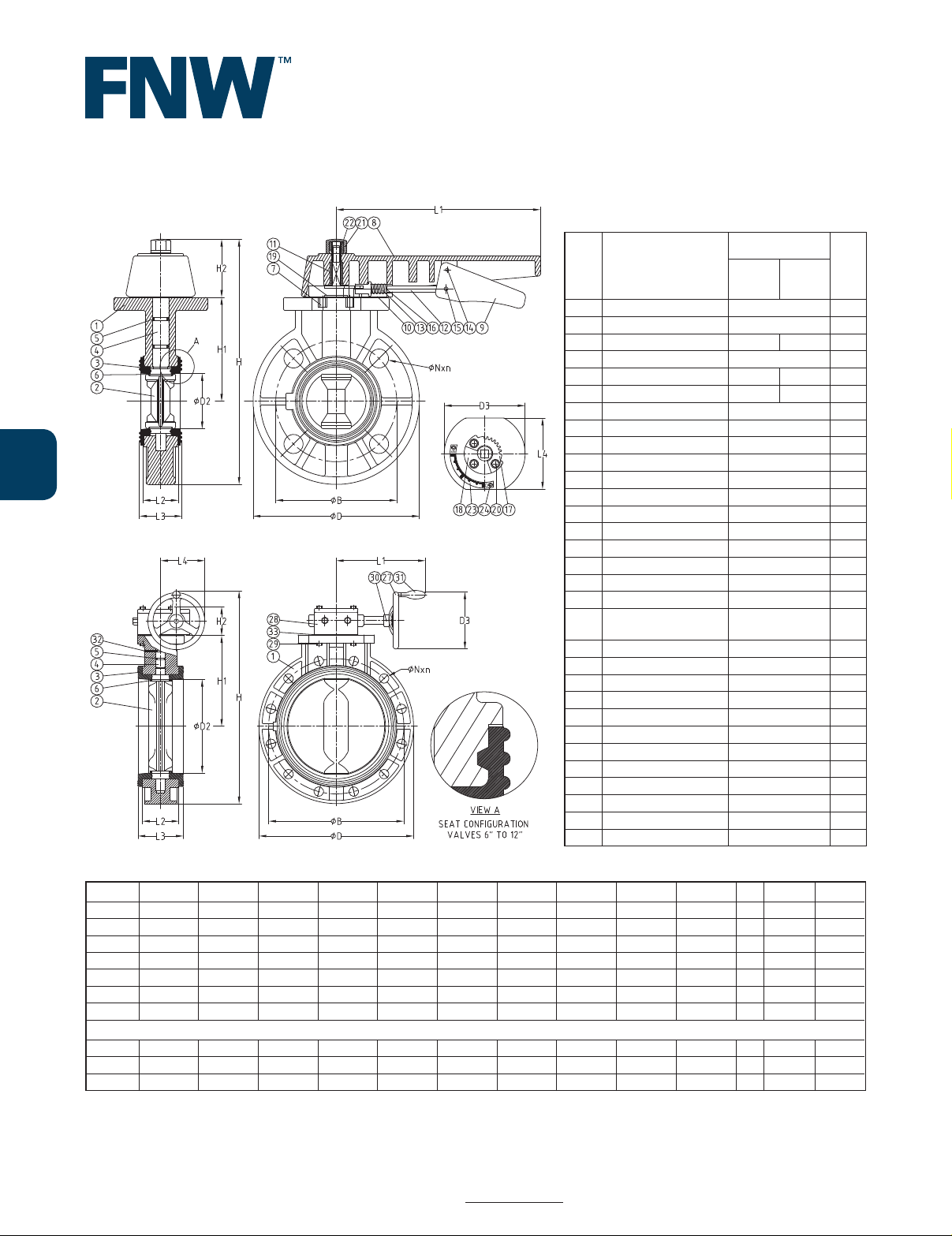
Ref.
No.
Description
Material
Qty
EPDM
Seat
Viton
Seat
1 Body UPVC 1
2 Disc UPVC 1
3 Seat EPDM Viton® 1
4 Stem 410SS 1
5 Stem O-ring EPDM Viton® 2
6 Disc O-ring EPDM Viton® 2
7 Insert Nut C3604 3
8 Handle PP 1
9 Release Lever PP 1
10 Spring Lock PP 1
11 Handle Insert Stainless Steel 1
12 Handle Lever 304SS 1
13 Spring 304SS 1
14 Upper Spring Pin 304SS 1
15 Lower Spring Pin 304SS 1
16 Washer 304SS 1
17 Locking Plate 304SS 1
18 Gear Seat UPVC 1
19
Stem Washer
(2" to 5")
304SS 1
20 Locking Plate Bolt 304SS 3
21 Handle Nut UPVC 1
22 Handle Nut Insert C3604 1
23 Position Scale 304SS 1
24 Rivet Stainless Steel 2
27 Hand Wheel FC 20 1
28 Gear Box CI 1
29 Bolt and Washer 304SS 4
30 Spring Pin Steel 1
31 Handwheel Handle Steel 1
32 Pin Stainless Steel 1
33 Packing EPDM 1
Standard Materials
Size ØD2 L1 L2 L3 ØB ØD H H1 H2 ØN n D3 L4
2 2.22 7.83 1.38 1.69 4.76 6.50 9.78 4.06 2.48 0.75 4 4.13 3.70
2-1/2 2.74 7.83 1.42 1.81 5.51 7.28 10.53 4.45 2.44 0.75 4 4.72 3.70
3 3.13 7.83 1.42 1.81 5.98 7.87 10.91 4.53 2.44 0.75 4 4.84 3.70
4 4.04 9.92 1.85 2.20 7.52 9.02 12.44 5.33 2.60 0.75 8 5.31 3.94
5 5.12 11.69 2.24 2.72 8.50 10.12 14.70 6.50 3.15 0.87 8 6.46 4.33
6 6.02 11.69 2.44 2.78 9.49 11.22 15.93 6.97 3.27 0.87 8 6.65 3.94
8 7.99 11.69 2.99 3.35 11.73 13.50 18.29 8.27 3.27 0.87 8 7.91 4.80
Gear Operated Figure 721
8 7.99 11.20 2.99 3.35 11.73 13.50 20.67 8.27 3.05 0.87 8 7.95 6.34
10 10.04 11.20 3.76 4.29 14.25 16.18 23.27 9.53 3.05 0.98 12 7.95 6.34
12 12.19 12.99 4.59 5.24 17.01 19.29 27.80 11.89 2.99 0.98 12 9.84 7.28
Dimensions (inches)
 Loading...