

Page 1
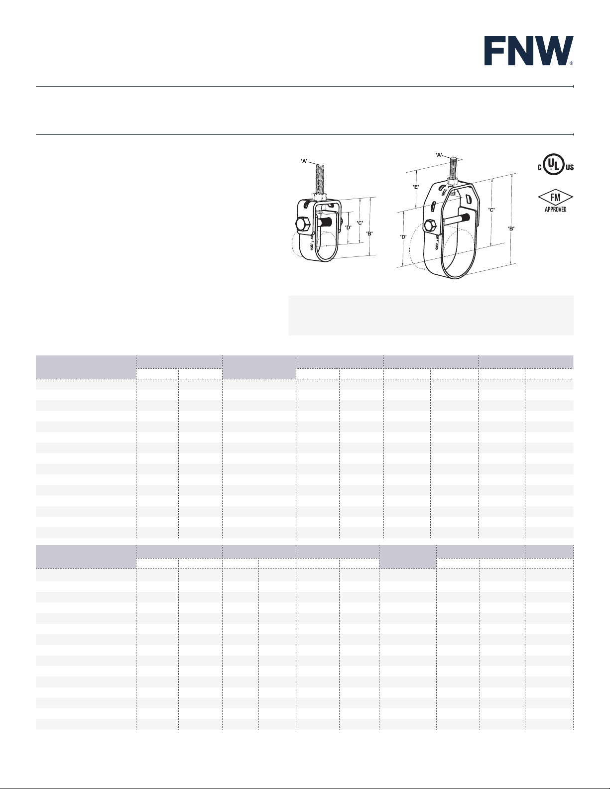
FIGURE 7005E
Hangers
Hangers
HANGERS
STANDARD DUTY ADJUSTABLE CLEVIS HANGERS
FEATURES
• Finish - Epoxy plated
• Color - Zinc
• UL/FM Approved - sizes 2-1/2" to 8"
• Hanger Body - ASTM A240
PRODUCT SPECIFICATIONS
Standards
• Design - MSS SP-58, Type 1
• Federal Specification - WW-H-171, Type 1
DIMENSIONS
1/2" to 1-1/4"
Note: A - Rod size (hanger rod and nuts not included), B - Bottom of pipe to top of hanger,
C - Center of pipe to top of hanger, D - Rod take out (center of pipe to bottom of hanger rod)
E - Minimum thread length of hanger rod, F - Adjustment, top of cross bolt to bottom of hanger
rod nut inside hanger
1-1/2" to 12"
Catalog Number
FNW7005EP0050
FNW7005EP0075 3/4 26.7
FNW7005EP0100 1 33.4
FNW7005EP0125 1-1/4 42.2
FNW7005EP0150 1-1/2 48.3
FNW7005EP0200 2 60.3
FNW7005EP0250
FNW7005EP0300
FNW7005EP0350
FNW7005EP0400
FNW7005EP0500
FNW7005EP0600
FNW7005EP0800
FNW7005EP1000
FNW7005EP1200
Catalog Number
FNW7005EP0050
FNW7005EP0075 3/4 26.7 2-1/2 63.5
FNW7005EP0100 1 33.4 2-1/2 63.5
FNW7005EP0125 1-1/4 42.2
FNW7005EP0150 1-1/2 48.3
FNW7005EP0200 2 60.3
FNW7005EP0250
FNW7005EP0300
FNW7005EP0350
FNW7005EP0400
FNW7005EP0500
FNW7005EP0600
FNW7005EP0800
FNW7005EP1000
FNW7005EP1200
Pipe Size
in. mm in. mm in. mm in. mm
1/2
2-1/2
3 88.9
3-1/2 101.6
4 114.3
5 141.3
6 168.3
8 219.1
10 273.1
12 323.9
Pipe Size E F
in. mm in. mm in. mm Lbs. kN Lbs.
1/2
2-1/2
3 88.9
3-1/2 101.6
4 114.3
5 141.3
6 168.3
8 219.1
10 273.1
12 323.9
21.3
73.0
21.3
73.0
A
Rod Size
3/8 - 16 2
3/8 - 16
3/8 -1 6
3/8 - 16 3-1/3 84
3/8 - 16 3-6/7 98
3/8 - 16 4-2/5
1/2 - 13 5-1/8
1/2 - 13 6
1/2 - 13 6-1/2
5/8 - 11 7-1/2
5/8 - 11 9-1/5
3/4 - 10 10-1/2
3/4 - 10 13
7/8 - 9 15-1/2
7/8 - 9 18-5/8
2-1/2
2-1/2 63.5
2-1/2 63.5
2-1/2
2-1/2
2-1/2
2-1/2
2-1/2
2-1/2
3
3-1/2
3-1/2
3-1/2
63.5 7/16 11.1 1/4 - 20UNC 610 2.71 0.12
63.5
63.5
63.5
63.5
63.5
63.5
76.2
88.9
88.9
88.9
B C D
2-2/7 58
2-2/3 68
234
267
328
394
473
1/2
5/8
7/8
1/3/16
1-5/8
2
2
2
2
2
2
2/5/16
2/5/16
2/5/16
12.7
15.9
22.2
30.2
41.3
50.8
50.8
50.8
50.8
50.8
50.8
58.7
58.7
66.7
50 1-1/2 39 3/8 9.5
112
130
151
166
190
1-3/4
2
2-4/9
2-7/8
3-1/5
3-2/3
4-1/7
4-1/2
5-1/6
6-3/8
7-1/8
8-1/2
10
12-1/8
Bolt Size
1/4 - 20UNC
1/4 - 20UNC
1/4 - 20UNC
1/4 - 20UNC 610 2.71
1/4 - 20UNC 610 2.71
3/8 - 16UNC 1130 5.02
3/8 - 16UNC 1130 5.02
3/8 - 16UNC 1130 5.02
3/8 - 16UNC 1430 6.36
1/2 - 13UNC 1430 6.36
1/2 - 13UNC 1940 8.62
5/8 - 11UNC 2000 8.89
3/4 - 10UNC 3600 16.00
3/4 - 10UNC 3800 16.89
44
51
62
73
81
93
105
114
131
162
181
216
254
308
Design Load Weight
610 2.71 0.14
610 2.71 0.16
610 2.71 0.24
5/8
7/8
1-1/4
1-3/4
1/15/16
2/5/16
2-3/4
3/1/16
3/11/16
4-5/8
5/5/16
6-1/2
7-5/8
9-3/4
15.3
22.5
31.90
44.9
49.4
57.9
69.2
78.2
93.6
117.0
134.8
164.7
194.2
247.6
0.25
0.35
0.61
0.71
0.79
1.00
1.67
3.05
4.11
6.75
7.88
FNW.COM
©2020 Ferguson Enterprises, LLC 1120 2266891 We reserve the right to modify or improve the designs or specifications of our products at any time without notice.
Page 2
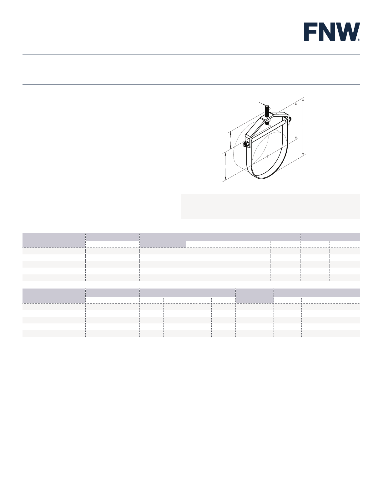
FIGURE 7005E
'A'
'C'
'B'
'E'
'D'
14” to 24”
HANGERS
STANDARD DUTY LARGE DIAMETER ADJUSTABLE CLEVIS HANGER
FEATURES
• Finish - Epoxy plated
• Color - Zinc
PRODUCT SPECIFICATIONS
Standards
• Design - MSS SP-58, Type 1
• Federal Specification - WW-H-171, Type 1
14" to 24"
Note: A - Rod size (hanger rod and nuts not included), B - Bottom of pipe to top of hanger
C - Center of pipe to top of hanger, D - Rod take out (center of pipe to bottom of hanger rod),
E - Minimum thread length of hanger rod, F - Adjustment, top of cross bolt to bottom of hanger
rod nut inside hanger
DIMENSIONS
Catalog Number
FNW7005EP1400
FNW7005EP1600
FNW7005EP1800
FNW7005EP2000
FNW7005EP2400
Catalog Number
FNW7005EP1400
FNW7005EP1600
FNW7005EP1800
FNW7005EP2000
FNW7005EP2400
Pipe Size
in. mm in. mm in. mm in. mm
14
16
18
20
24
in. mm in. mm in. mm Lbs. kN Lbs.
14
16
18
20
24
355.6 1 - 8
406.4 1 - 8
457.2 1 - 8
508.0 1-1/4 - 7
609.6 1-1/4 - 7
Pipe Size E F
355.6 4
406.4
457.2
508.0 5
609.6 5
Rod Size
4
4-1/2
A
23-1/2 596.5 14-3/4 380.8 12-7/8 327.0
29-2/3 754.0 19 486.0 17/7/16 442.9
33-7/9 858.0 21-1/8 539.2 20" 485.5
101.6 2-7/8 73.0 1 - 8UNC 4200 18.67 18.15
101.6 3-3/8 85.7 1 - 8UNC 4600 20.44 23.84
114.3 3-3/8 85.7 1 - 8UNC 4800 21.33 26.79
127.0 4/13/16 122.2 1-1/4 - 7UNC 4800 21.33 43.53
127.0 5-1/4 133.3 1-1/4 - 7UNC 4800 21.33 50.39
B C D
21-1/6 537.5 13-5/8 347.2 11/3/16 281.6
27 683.5 17-3/8 442.4 13-15/16 354.0
Bolt Size
Design Load Weight
FNW.COM
©2020 Ferguson Enterprises, LLC 1120 2266891 We reserve the right to modify or improve the designs or specifications of our products at any time without notice.
 Loading...