

Page 1
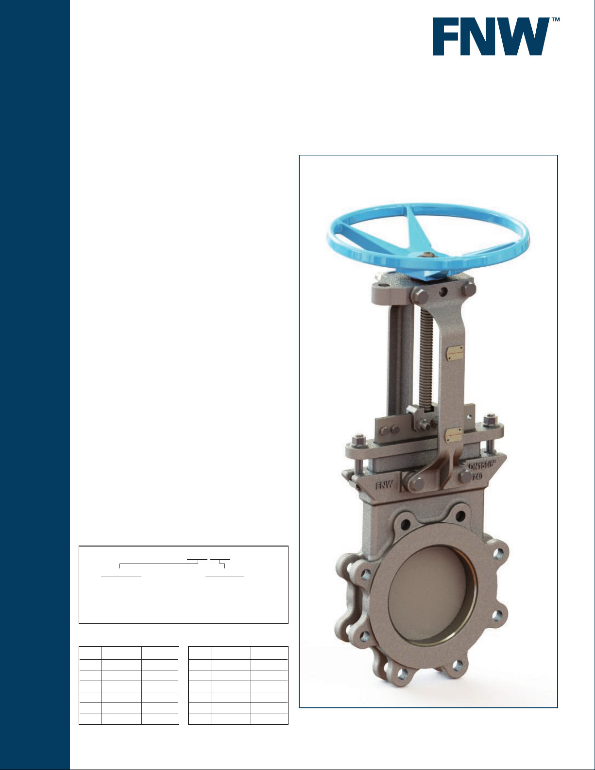
Figure 6800
KNIFE GATE VALVES
STAINLESS STEEL BIDIRECTIONAL
RESILIENT SEATED KNIFE GATE VALVE
The gure 6800 knife gate valve has an all cast stainless steel
body and yoke with investment cast packing follower. It is a
general purpose zero-leak bidirectional shutoff valve. Perimeter
gate sealing is not pressure dependent, so there is no minimum
differential needed for shutoff. Port sizing is similar to schedule
40 pipe, so the valve offers unrestricted fl ow and minimal
pressure drop.
Features
• Bidirectional Bubble-Tight Shutoff
• Maximum Pressure: 150 PSI CWP (30” is 50 PSI CWP)
• Maximum Temperature: 176°F (80°C)
• Non-Differential Pressure Dependent Shutoff
• Cast Stainless Steel Body, Yoke, & Packing Gland
• Thrust Needle Bearing
• Combination Chest Liner & Anti-Extrusion Strip
(Anti-Extrusion Strip Only on 14” and Larger Valves)
• Wire Reinforced & Retained Resilient Seat
• Stainless Steel Position Indication Arrow
• Stainless Steel Hardware
• Machined Gland Pocket Area
• Bonnetless, Outside Screw & Yoke
• Rising Stem
• Cast Iron Hand Wheel
• Gear-Operator Standard on 30” Valve
• Available in sizes 3” to 30”
• Standard design accommodates locking device
Standards
• Face-to-Face: MSS SP-81
• Flange Drilling: ANSI B16.5 (30” to MSS SP-44 Flanges)
• Testing:
○ Shell (Before Assembly): 1.5 Time Max. CWP (No Leak)
○ Seat: 1.1 Times Max. CWP (No Leak)
• Material: ASME B16.34
Figure Number Matrix
FNW 6800 Seat Size
SEAT CODE
Buna (Nitrile) = B
(SS Wire Reinforced)
3 = M
4 = P
6 = U
8 = X
SIZE CODE
10 = 10
12 = 12
14 = 14
16 = 16
18 = 18
20 = 20
24 = 24
30 = 30
Cv & Weight
Size Cv Wt (Lbs)
3 565 44
4 1,040 53
6 2,440 88
8 4,460 139
10 6,250 181
12 9,400 229
Weights are for general reference only.
Size Cv Wt (Lbs)
14 12,500 364
16 16,500 397
18 21,400 463
20 27,000 573
24 39,700 617
30 60,000 882
www.fnw.com
Page 2
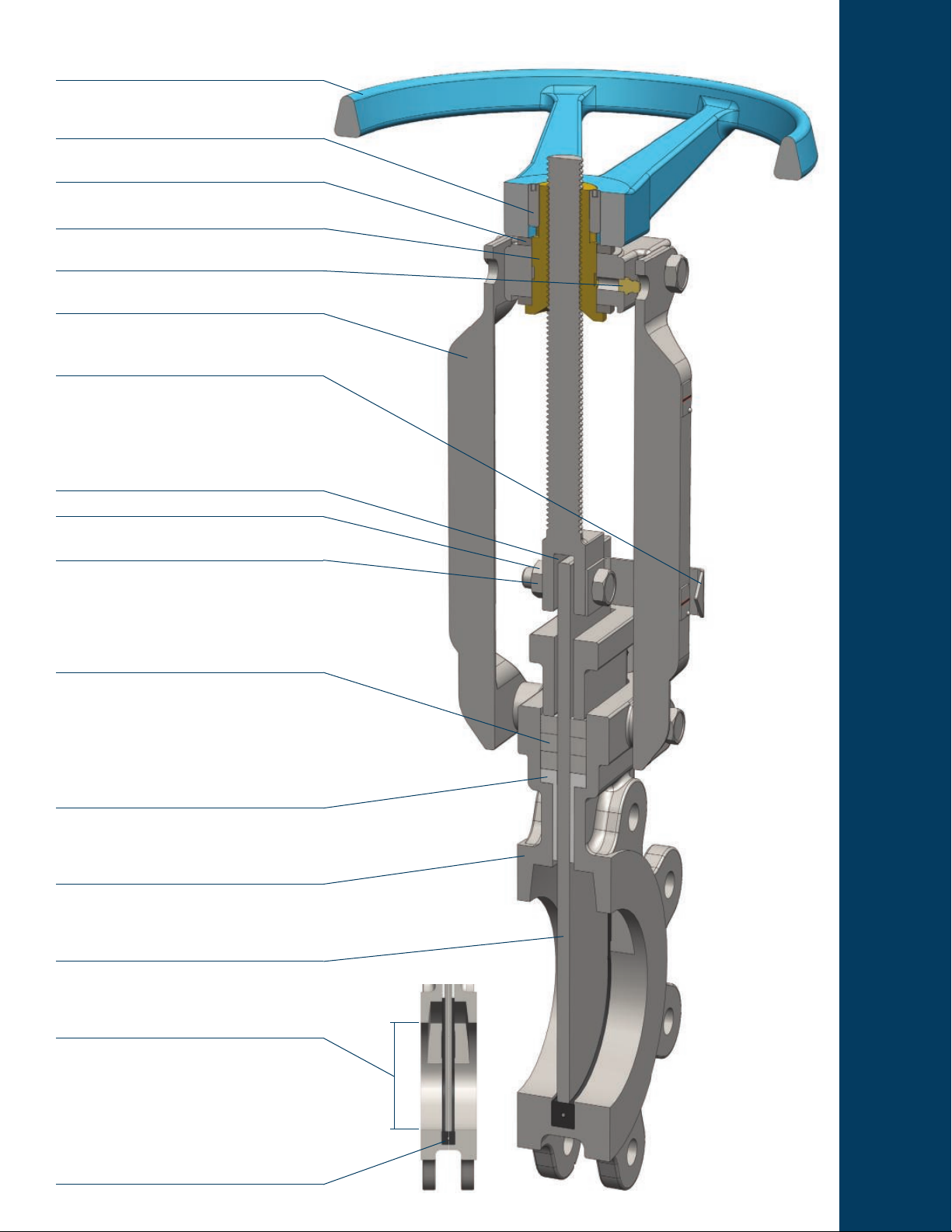
Hand wheel is heavy cast iron, with a rounded grip
and epoxy coated hand wheel.
Double set screws prevent threaded-on hand
wheel from backing off or coming loose.
Stainless steel needle bearings reduce hand wheel
rim pull force.
Aluminum-Bronze thrust components for antigalling operation.
Grease tting for maintaining smooth drive sleeve
operation.
Cast stainless steel yoke arms provide optimum
fl exural rigidity.
Stainless steel position indication arrow is
standard
Stem-to-gate clevis is deliberately loose to allow
play in gate to minimize binding.
Stainless steel hardware is standard.
Horizontal clevis bolts provide fl exibility of the gate
during travel.
FEATURES
Multiple layers of PTFE impregnated square braid
packing provides excellent gland sealing at full
valve pressure differential.
Combination PTFE chest liner & anti-extrusion
strips (anti-extrusion strips only on 14” and larger
valves), enhance packing functionality while
centering the gate. They also act as a gate wiper,
and support the gate in horizontally mounted
valves.
The single piece cast all stainless steel body is
rugged and compact. It offers better leak tightness
than fabricated or two-piece designs.
The gate is high-quality, ground- nished stainless
steel. A generous gate thickness is well supported
by the packing.
Port sizing is similar to schedule 40 pipe, so the
valve offers unrestricted fl ow and minimal pressure
drop.
Perimeter gate sealing is not pressure dependent,
so there is no minimum differential needed for
shutoff.
Page 3

Secured Wire
Reinforcement
Gate/Seat
Interference Fit
Perimeter Seat
Seat Seal Confi guration
The gure 6800 knife gate valve provides
bubble-tight shutoff. When the valve is closed,
there is a friction t along the entire perimeter
between the fl at edge of the gate and the
elastomer seat. This friction t ensures tight
shutoff without the requirement of a minimum
line pressure, but is tight enough to maintain
shutoff at maximum rated pressures as well.
There is no recommended fl ow direction
because the seal is made at the gate’s edge,
hence bidirectional fl ow capability.
Seat seal retention is twofold. First, the seat is
retained in a channel with a machined retention
Resilient Seat
Reinforcement Wire
Retention Lip
lip. This lip overhangs both sides of the seat,
preventing seat removal from high velocity
fl ows. Secondly, the seat is reinforced with a heavy stainless steel wire. The ends of the wire
are wrapped around gland bolts. The wire adds rigidity to the seat form which also prevents seat
movement during high fl ow or valve opening/closing operation.
Standard Materials
Ref.
Description Material Qty
No.
1 Body
1A Seat
2 Gate
3 Packing
Chest Liner
Anti
5
Extrusion
Strip
6 Gland
7 Gland Bolt
8 Gland Nut
9 Yoke Arm
10 Yoke Bolt
11 Stem
12 Clevis Bolt
13 Clevis Nut
14 Collar
15 Collar Bolt
16 Collar Nut
17 Hand Wheel Cast Iron, ASTM A126 Gr. B 1
18 Yoke Sleeve
Thrust
19
Needle
Bearing
20 Set Screws Stainless Steel, 304SS 2 (3”~24)
Position
21
Indicator
30 Gear-Op
Stainless Steel, ASTM A351
Gr. CF8M
Buna (Nitrile) with ASTM
A276 Type 304 Wire
Stainless Steel, ASTM A240
Type 316
PTFE Impregnated Syntex
Fiber
PTFE
Stainless Steel, ASTM A351
Gr.CF8
Stainless Steel 304,
ASTM A193 Gr. B8
Stainless Steel 304,
ASTM A194 Gr. 8
Stainless Steel, ASTM A351
Gr.CF8
Stainless Steel 304,
ASTM A193 Gr. B8
Stainless Steel, ASTM A276
Type 304
Stainless Steel 304,
ASTM A193 Gr. B8
Stainless Steel 304,
ASTM A194 Gr. 8
Stainless Steel, ASTM A351
Gr.CF8
Stainless Steel 304,
ASTM A193 Gr. B8
Stainless Steel 304,
ASTM A194 Gr. 8
Aluminum Bronze,
ASTM B148, UNS C95200
Stainless Steel, 2 (3”~24)
Stainless Steel, 304SS 1
Enclosed Type
Model BG03 (not shown)
1
1
1
3 (3”~24”)
4 (30”)
2 (3”~12”)
2 (14”~30”)
1
2~10
2~10
2
4
1
2
2
1 (3”~24)
2 (3”~8”)
4 (10”~24”)
2 (3”~8”)
1 (3”~24)
1 (30” only)
Page 4

Figure 6800
KNIFE GATE VALVES
STAINLESS STEEL BIDIRECTIONAL
RESILIENT SEATED KNIFE GATE VALVE
Dimensions (inches)
Size A B C D E F G H J K N S
3 2.00 6.00 5.00 16.34 19.49 9.84 2 5/8”-11 0.39 2 2.95 0.47
4 2.00 7.50 6.22 18.31 21.26 9.84 2 5/8”-11 0.39 6 4.00 0.47
6 2.25 9.50 8.50 22.05 27.36 11.75 2 3/4”-10 0.43 6 6.00 0.57
8 2.75 11.75 10.63 25.59 33.27 15.98 2 3/4”-10 0.43 6 8.00 0.57
10 2.75 14.25 12.76 28.66 39.37 15.98 4 7/8”-9 0.49 8 10.04 0.69
12 3.00 17.00 14.76 33.46 46.46 20.00 4 7/8”-9 0.43 8 11.97 0.69
14 3.00 18.75 16.26 37.60 53.15 20.00 4 1”-8 0.51 8 13.11 0.75
16 3.50 21.25 18.50 41.34 58.27 20.00 6 1”-8 0.63 10 15.00 0.87
18 3.50 22.75 20.98 45.67 63.78 20.00 6 1-1/8”-7 0.59 10 16.93 0.94
20 4.50 25.00 23.03 50.39 70.47 20.00 8 1-1/8”-7 0.75 12 18.82 0.98
24 4.50 29.50 27.24 58.46 83.66 20.00 8 1-1/4”-7 0.91 12 22.64 0.98
30 4.62 36.00 33.75 81.00* 110.00 19.68 10 1-1/4”-7 0.94 18 28.74 1.12
* Dimension “D” for 30” valve is centerline of valve to centerline of gear-operator hand wheel shaft.
DOC: FNW680013 Ver. 8/2014
© 2014 - FNW. All rights reserved. 22038
The FNW logo is a trademark of Ferguson Enterprises, Inc., PL Sourcing, PO Box 2778, Newport News, VA 23609
The contents of this publication are presented for information purposes only, and while effort has been made to ensure their accuracy, they are not to be construed as
warranties or guarantees, expressed or implied, regarding the products or services described herein or their use or applicability. All sales are governed by our terms and
conditions, which are available on request. We reserve the right to modify or improve the designs or specications of our products at any time without notice. Always
verify that you have the most recent product specications or other documentation prior to the installation of these products.
 Loading...