

Page 1
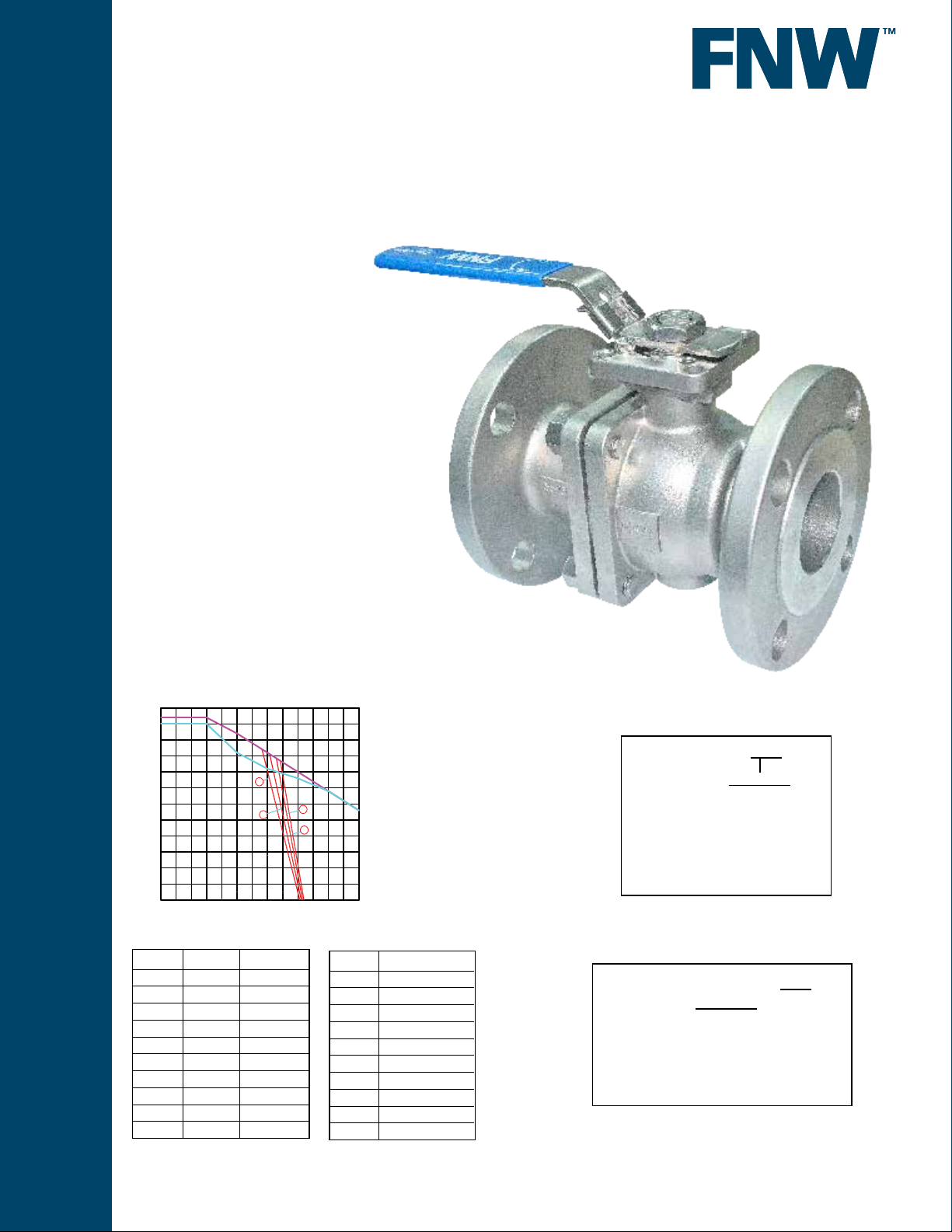
Figure 600B
-1/2”
P
r
e
s
s
u
r
e
p
s
i
(38)
300
(-18)(-29)
(316° )(204) (260)(93) (149)
21
C
STAINLESS STEEL BALL VALVES
2 PC FULL PORT 150# FLANGED
Features:
• Full Port
• 150 WSP
• Flanged Connection
• TFM Seats
• Stainless Steel Trim
• Anti Static Design
• Blow-out Proof Stem
• Investment Cast Body
• Adjustable Packing
• Locking Device
• Actuator Mounting Pad
• Manufactured Silicone Free
• Sizes 1/2” to 8”
Standards:
• Design: ASME B16.34
• Pressure Test: API 598
• Flange Dimensions: ASME B16.5
• Materials: ASME B16.34
• Mounting Pad: ISO 5211
• NACE MR-01-75 Approved
C
la
s
s
1
s
100
5
0
W
s
1
5
0
C
B
B
M
200
o
d
y
B
o
d
y
4
2
3
1
300
400
C
F
8
500
600°
17.5
14
10.5
7
3.5
0
r
a
b
e
r
u
s
s
e
r
P
F
1/2"to1"1.
2. 1-1/4"to2
3. 3"&4"
4. 5"&6"&8"
Torque
Size Torque (in-lbs)
1/2 57
3/4 69
1 115
1-1/2 218
2 334
2-1/2 517
3 828
4 1265
6 3520
8 4947
* Figures do not include safety factor
30% factor is recommended when sizing
actuator
C
l
0
-20 0
a
250
200
150
100
50
Cv & Weight
Size Cv Wt (lbs)
1/2 18 3.52
3/4 36 4.71
1 48 6.34
1-1/2 165 12.98
2 207 18.66
2-1/2 450 30.14
3 780 38.61
4 1360 65.52
6 2600 163.00
8 4200 282.00
Figure Number Matrix
FNW 600B Size
SIZE CODE
1/2 = D
3/4 = F
1 = G
1-1/2 = J
2 = K
2-1/2 = L
3 = M
4 = P
6 = U
8 = X
Repair Kits (Order Separately)
FNW 600BRKTFM Size
SIZE CODE
1/2” = D
3/4” = F
1” = G
1-1/2” = J
2” = K
2-1/2” = L
3” = M
4” = P
6” = U
www.fnw.com
Page 2
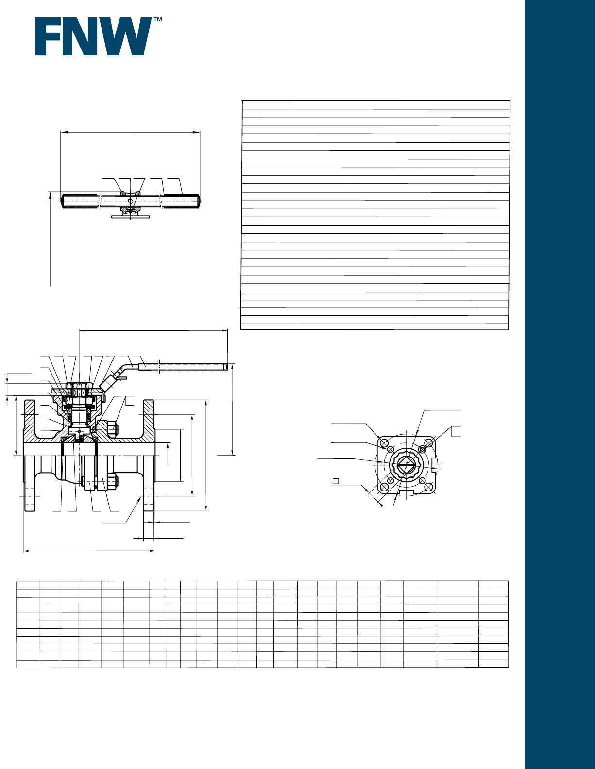
Figure 600B
E
n
d
C
a
p
1
2
8
W
H
1
W
Ø
D
ir
e
c
t
m
o
u
n
t
p
a
d
3
2
282.00
4,947
8”
7.97
18.0
10.63
13.5
11.75
1.06
0.06
8
7/8
9.96
13.15
1.06
1.063
0.55
non
4.92
non
31.6
F12
Dimensions
STAINLESS STEEL BALL VALVES
1/2”- 8”
B
o
d
2
3
4
5
6
"
:3
~
8
S
I
Z
2
4
2
6
1
5
1
4
1
3
1
2
1
1
1
0
M
1
9
8
9
1
7
"
E
5
2
6
2
7
2
8
8
1
7
1
"
/
2
1
-
2
"
~
/2
:1
E
I
Z
S
0
2
1
2
6
H
5
7
8
9
1
0
1
1
1
2
1
3
1
4
1
5
1
6
1
7
1
8
1
9
2
0
2
1
2
2
2
3
2
4
2
5
2
6
2
7
1
H
y
B
a
ll
e
a
t
B
a
ll
S
S
t
e
m
S
(
A
n
t
i-
t
W
a
T
s
h
s
ru
O-Ring
Packing
Bushing
Gland
Belleville Washer
S
tem Nut
Handle Nut
Stop-lock-cap
le
Gland
H
a
n
d
Lock Device
Handle
l
e
S
le
H
a
e
n
d
Body Gasket
Bolt Nut
Bolting
Stop Bolt
Stop Nut
l
e
A
d
a
H
a
S
e
B
olting
Pipe Handle
H
a
p
n
d
c
r
e
w
t
S
le
S
l
n
e
d
e
Standard Materials
ic
e
ta
t
ic
h
e
r
v
e
t
e
r
v
e
)
D
e
v
2-1/2
(1-2" ~
2-1/2
(1-2" ~
2-1/2
(1-2" ~
2-1/2
(1-2" ~
8
"
(3
"~
8
"
(3
"~
8
"
(3
"~
8
"
(3
"~
8
"
(3
"~
2
U
-Ø
4
1
U
-
Ø
4
"
)
"
)
"
)
"
)
)
)
)
)
)
(
IS
C
C
C
6
0
T
F
M
1
S
5
0
S
%
A194-8
A194-8
A193-B8
A
5
3
VINYL PLASTIC
)
1
1
2
5
O
F
8
F
8
F
8
0
+
3
1
P
T
F
FKM
PTFE
+
5
0
3
16
301
3
0
3
0
3
0
3
0
3
0
3
0
PTFE
A2-70
A2-70
C
A
2
A
2
Z
n
+
Ø
M
M
M
2
6
%
4
4
4
4
4
4
F
-
7
-
7
E
0
%
E
P
8
0
0
P
LATED
2
G
F
T
F
E
Dimensions
2
2
1
d
Ø
D
R
C
Ø
Ø
Ø
E
P
4
S
1
3
1-
2-1
d
E
I
Z
"
/2
"
/4
"
1
"
/2
1
"
2
"
/2
"
3
"
4
"
6
4
9
.
5
0
4
9
.
7
0
5
8
.9
0
6
0
.5
1
7
.9
1
7
7
0
.5
2
8
9
.9
2
4
.
9
3
9
1
1
.
9
5
2
3
1
h
-
Ø
N
f
T
L
R
L
5
.2
2
.
6
0
.
0
0
.5
0
.0
0
.5
0
.0
0
.0
.5
5
3
8
.
3
1
3
9
.
6
1
1
.0
2
4
5
8
.
8
2
2
.
6
3
6
7
2
.1
4
0
.0
5
7
9
.1
6
9
0
.5
8
1
1
Torque (in lbs)
1
2
5
O
D
0
.5
8
.8
5
.2
0
.
0
0
.0
0
.0
0
.
5
0
.0
.0
1
T
C
.3
0
8
.3
2
.3
0
5
.7
2
.
0
2
.
1
3
8
.8
3
.5
0
.5
0
5
.
7
4
.6
0
0
.5
5
.6
0
0
.0
6
.8
0
0
.
5
7
.9
0
0
.
5
9
N
f
1
4
6
.0
0
4
6
.0
0
4
8
3
6
.0
0
4
6
.
0
0
4
0
4
6
6
.0
0
2
6
.0
0
4
4
6
.0
9
0
8
6
.0
0
8
8
4
6
.0
0
3
.9
1
/8
5
/8
5
9
.0
2
/
8
5
2
.3
2
/8
5
9
.
9
2
3
.2
3
/4
3
2
.0
4
/4
3
/4
3
1
.4
4
1
.5
5
/4
3
/8
7
9
.9
7
0
.
3
0
1
.1
3
1
.3
3
5
.3
0
4
.
5
3
3
.4
0
3
.
3
4
5
.5
0
5
.5
0
3
.
5
4
7
.6
0
1
.9
5
7
.
6
0
3
.9
6
7
.8
0
1
.
3
8
6
8
.
0
1
.1
1
1
M
1
H
H
h
U
P
4
5
.3
0
4
5
.3
0
3
3
.4
0
1
5
.5
0
1
5
.5
0
9
6
.6
0
9
6
.
6
0
6
6
.
8
0
0
3
6
.0
1
4
.2
0
4
.2
0
4
.2
0
4
.
2
0
8
.
2
0
8
.2
0
5
.
3
0
5
.3
0
n
o
n
5
.
5
1
8
1
.2
0
8
.
2
0
1
5
.3
0
1
1
5
.3
0
2
3
.4
0
2
3
.4
0
3
.
4
0
n
o
n
4
5
.6
1
2
.
4
7
.9
1
2
.
4
7
.9
1
5
.6
6
.7
2
7
.9
6
.7
2
7
.9
2
.0
4
6
.
7
2
.
0
4
6
.7
n
o
n
2
.
0
4
n
o
n
2
.
9
2
E
1
E
2
U
1
IS
W
7
.7
5
7
.7
5
5
.9
6
5
.7
7
5
.7
7
.5
0
1
.9
1
1
.
8
5
1
.6
1
3
4
0
F
~
3
0
F
5
0
F
~
3
0
F
5
0
F
~
4
0
F
~
5
0
F
F
~
5
0
F
~
7
0
F
~
7
0
F
1
F
1
F
115
7
0
F
218
334
7
0
0
517
1
F
828
0
1
F
0
1,265
3,520
2
Weight (lbs)
57
69
3.52
4.71
6.34
12.98
18.66
30.14
38.61
65.52
163.00
DOC: FNW600B Ver. 3/2018
© 2018 - FNW. All rights reserved.
The FNW logo is a trademark of Ferguson Enterprises, Inc., PL Sourcing, PO Box 2778, Newport News, VA 23609
The contents of this publication are presented for information purposes only, and while effort has been made to ensure their accuracy, they are not to be construed as
warranties or guarantees, expressed or implied, regarding the products or services described herein or their use or applicability. All sales are governed by our terms and
conditions, which are available on request. We reserve the right to modify or improve the designs or specications of our products at any time without notice. Always
verify that you have the most recent product specications or other documentation prior to the installation of these products.
 Loading...