

Page 1
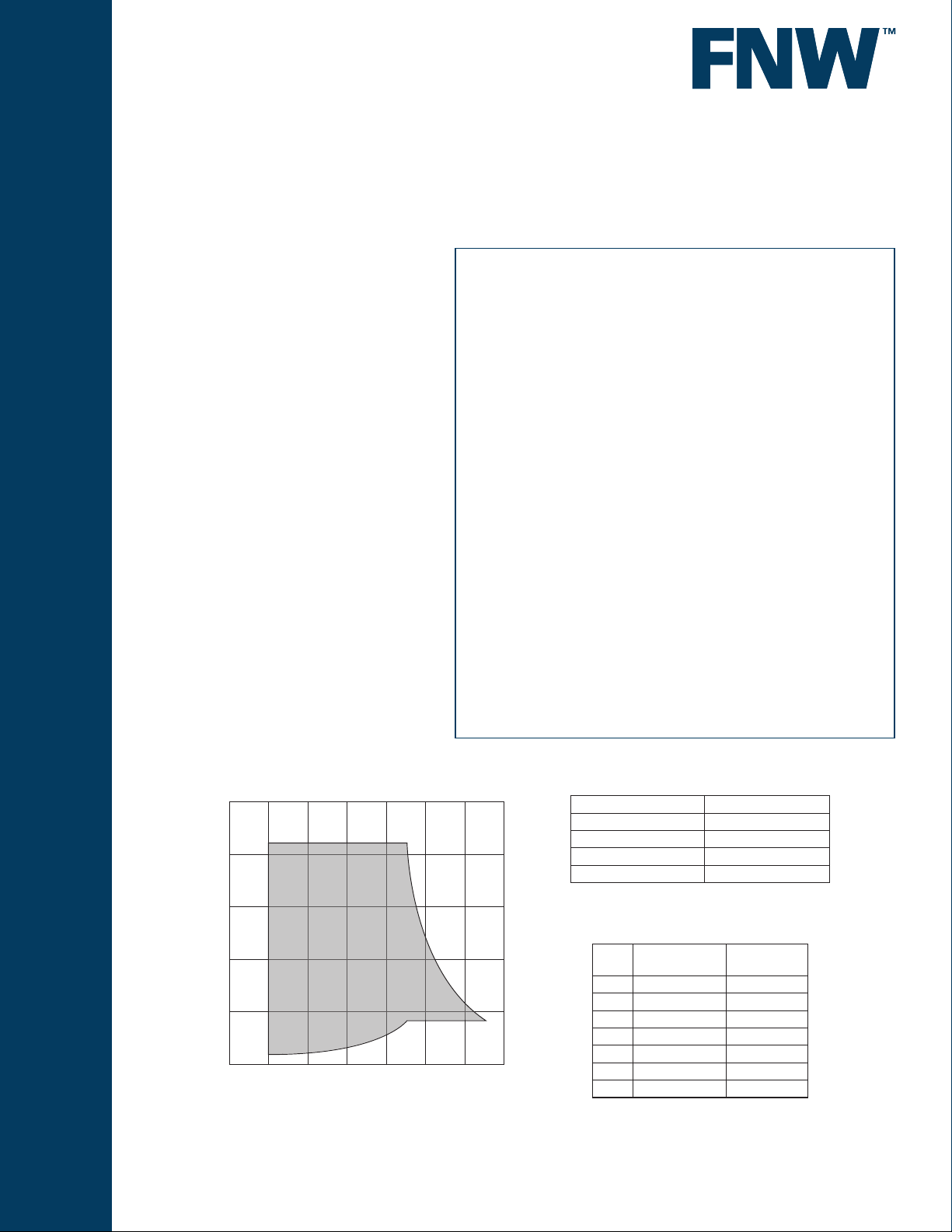
Figure 40
FLEXIBLE CONNECTORS
SINGLE SPHERE
FLEXIBLE CONNECTOR
Flexible connectors are used to absorb thermal and seismic
movement, absorb hydraulic shock, provide vibration and
noise dampening, ease installation and correct minor
misalignment of piping and components. They come
in a variety of sizes, materials, and connection ends for
numerous applications.
Similar to the metal exible connectors in application
advantages, single sphere exible connectors are suitable
for pressure and vacuum services. The spherical shape
is stronger than cylindrical elastomer connectors and
disperses pressure evenly over a larger surface area. The
streamline shape also reduces turbulence and sediment
build-up and lessens deformation while under pressure. The
elastomer allows greater movements in the axial, elongation,
lateral, and angular directions and provides a wide service
range due to its chemical resistance characteristics.
Pressure / Temperature*
290
232
145
Pressure (PSI)
72
0
25.59”Hg
-4 32 68 104 140 176 194
-40
Temperature (°F)
* Figure 40 should not be used at the maximum working pressure
and working temperature at the same time.
www.fnw.com
Ratings
Max. Working Pressure 232 PSI
Test Pressure 348 PSI
Burst Pressure @ 80°F 850 PSI
Vacuum Rating 25.59”Hg (650 Torr)
Operating Temperature -4°F to 194°F
Part Numbers & Weight
Size Part Number
2-1/2 FNW40L 14.74
3 FNW40M 16.50
4 FNW40P 18.26
5 FNW40S 23.98
6 FNW40U 31.68
8 FNW40x 42.24
10 FNW4010 55.00
Approx. Wt
(Lbs)
Page 2
FLEXIBLE CONNECTORS
SINGLE SPHERE
FLEXIBLE CONNECTOR
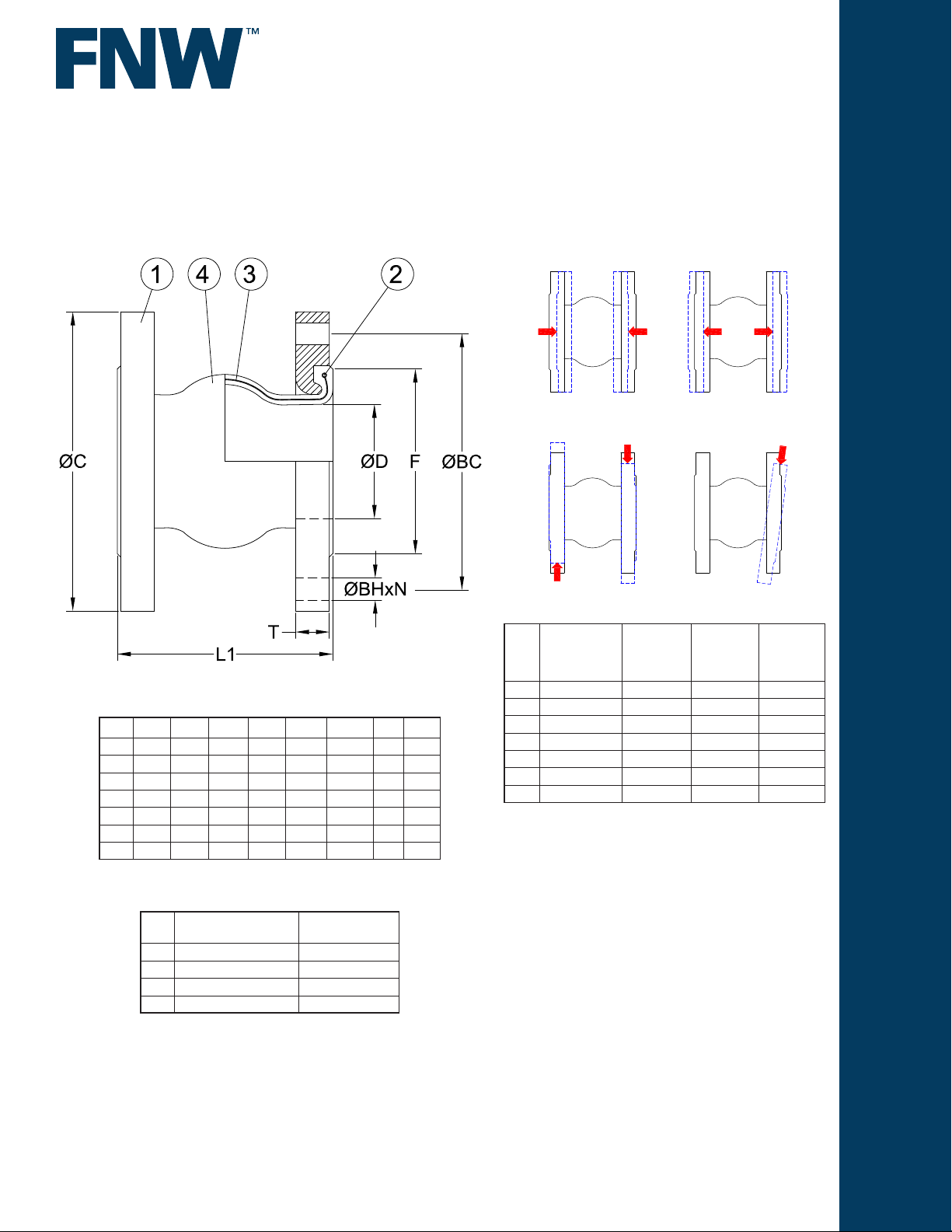
Braid Limits
Figure 40
Dimensions (inches)
Size ØC ØD F L1 ØBC ØBH N T
2-1/2 7.0 2.68 4.17 6.0 5.50 0.75 4 0.71
3 7.5 2.99 4.57 6.0 6.00 0.75 4 0.71
4 9.0 4.06 5.91 6.0 7.50 0.75 8 0.71
5 10.0 5.04 7.09 6.0 8.50 0.87 8 0.79
6 11.0 5.98 8.23 6.0 9.50 0.87 8 .87
8 13.5 7.64 10.24 6.0 11.75 0.87 8 .87
10 16.0 9.84 12.60 8.0 14.25 1.00 12 .94
Axial Compression
Transverse Movement
Maximum
Size
2-1/2 0.500” 0.375” 0.50” 15°
3 0.500” 0.375” 0.50” 15°
4 0.625” 0.375” 0.50” 15°
5 0.625” 0.375” 0.50” 15°
6 0.625” 0.375” 0.50” 15°
8 0.625” 0.375” 0.50” 15°
10 0.625” 0.500” 0.75” 15°
Axial
Compression
Maximum
Axial
Elongation
Axial Elongation
Angular Deection
Maximum
Transverse
Movement
Maximum
Angular
Deection
Standard Materials
Ref.
No.
1 Flange Carbon Steel
2 Reinforcement Wire Carbon Steel
3 Reinforcement Fabric Synthetic Fiber
4 Elastomer Sleeve EPDM
DOC: FNW4005 Ver. 3/2012
© 2012 - FNW. All rights reserved.
The FNW logo is a trademark of Ferguson Enterprises, Inc., PL Sourcing, PO Box 2778, Newport News, VA 23609
The contents of this publication are presented for information purposes only, and while ef
warranties or guarantees, expressed or implied, regarding the products or services described herein or their use or applicability. All sales are governed by our terms and
conditions, which are available on request. We reserve the right to modify or improve the designs or specications of our products at any time without notice. Always
verify that you have the most recent product specications or other documentation prior to the installation of these products.
Description Material
fort has been made to ensure their accuracy, they are not to be construed as
 Loading...