

Page 1
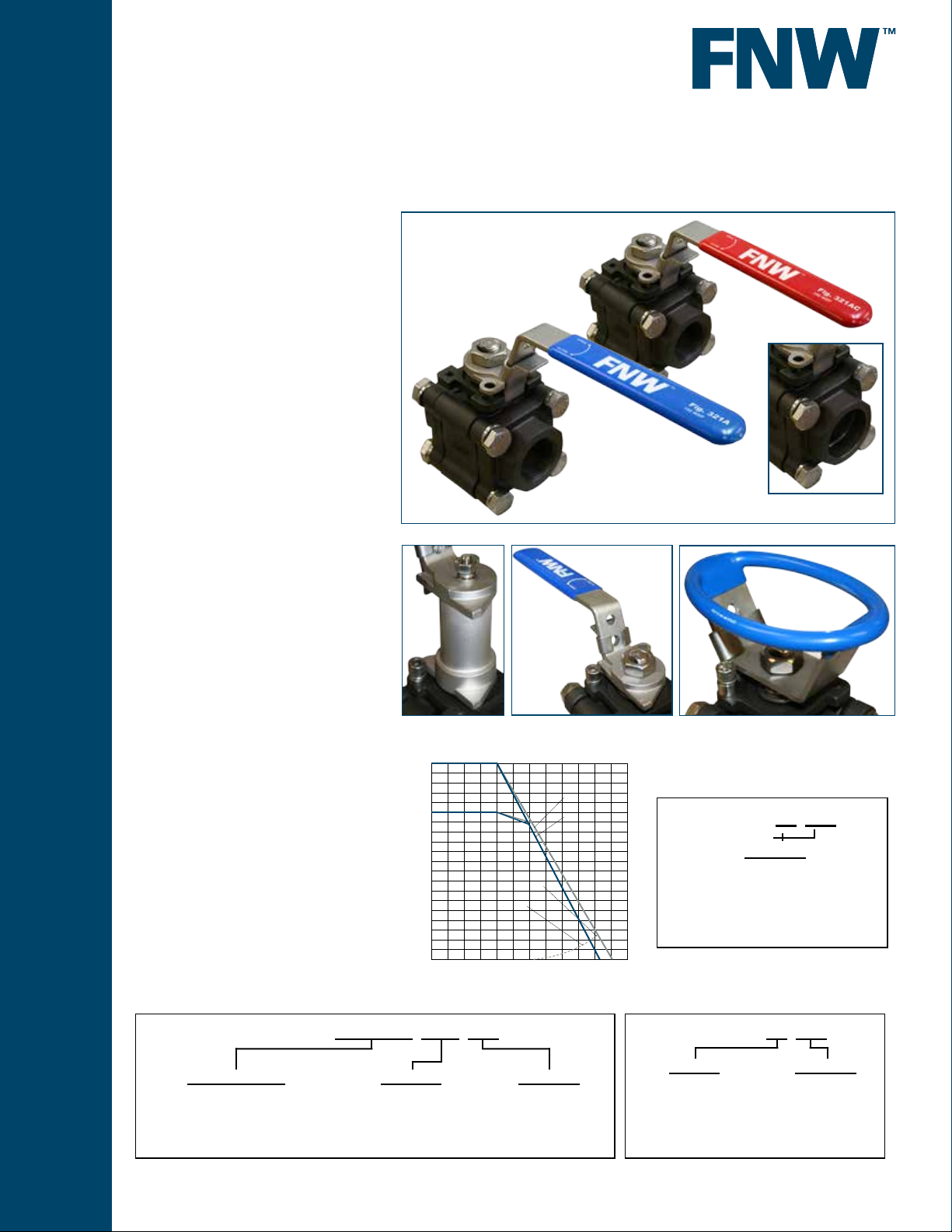
Figure 321A
Pressure (PSIG)
CARBON STEEL BALL VALVES
3 PC FULL PORT 2000 CWP
Features:
• 2000 PSI CWP* Non-Shock
• Working Steam Pressure (WSP)
• 150 PSI - Fig. 321A
• 250 PSI - Fig. 321AC
• Full Port
• Blow-out Proof Stem
• Live-Loaded Packing
• Anti-static Design
• Investment Cast Body
• TFM (Super TFE) Seats
• End Connections
• Threaded
• Socket Weld
• Stainless Steel Handle
• Locking Lever
• Tapped Hole Mounting Pad
• Vacuum rated to 26.967”Hg (75 Torr)**
• Vented Ball
• Manufactured Silicone Free
• Replacement Locking Handle
Kits Available (1/4”~2”)
• Optional Stem Extension Kit (Uses Existing
Valve Handle)(1/4”~2”)
• Optional Oval Handle Kit (1/4”~1-1/4”)
Fig. 321AC
Fig. 321A
Accessories
Optional Socket
Weld Ends
Standards:
• Design: ASME B16.34,
MSS SP-110
NACE MRO103 AND MRO175 Approved
• End Connections:
• NPT - ASME B1.20.1
• SW - ASME B16.11
• Seat/Shell Test: MSS SP-110
* 1/4” to 1” - 2000 PSI CWP
1-1/4” to 2” - 1500 PSI CWP
** Vacuum measurements are often made
in inches of mercury below atmospheric
pressure. The values calculated here assume
standard atmospheric pressure of 29.92
Figure Number Matrix
FNW 321A Seat/Seals Ends Size
SEAT/SEAL CODE
Blank = Standard Temp (150 WSP)
C = High Temp (250 WSP)
Stem Extensions
(1/4”~2”)
1/4” ~ 1”
2000
1800
1600
1-1/4” ~ 2”
1400
1200
1000
800
600
400
200
-20 0 100 200 300 400 500
END CODE
Blank = Threaded NPT
SW = Socket Weld
Replacement Locking
Handles Kits (1/4”~2”)
TFM-4215
TFM-1600+20%GF
250 WSP
150 WSP
Saturated Steam Curve
Temperature (°F)
SIZE CODE
1/4 = B
3/8 = C
1/2 = D
3/4 = F
1 = G
1-1/4 = H
1-1/2 = J
2 = K
Oval Handle Kits (1/4”~1-1/4”)
Repair Kits (Order
FNW 320A Kit Size
SIZE CODE
1/4”-3/8” BC
1/2” = D
3/4” = F
1” = G
1-1/4” = H
1-1/2” = J
2” = K
Kit Codes (Order Separately)
FNW 320A Kit Size
KIT TYPE
Locking Handle = LHK
Stem Extension = SEK
Oval Handle = OH
Note: The Figure 321A uses the same accessories
as the 320A.
SIZE CODE
1/4”~3/4” = BF
1”~1-1/4” = GH
1-1/2”~2” = JK
www.fnw.com
Page 2
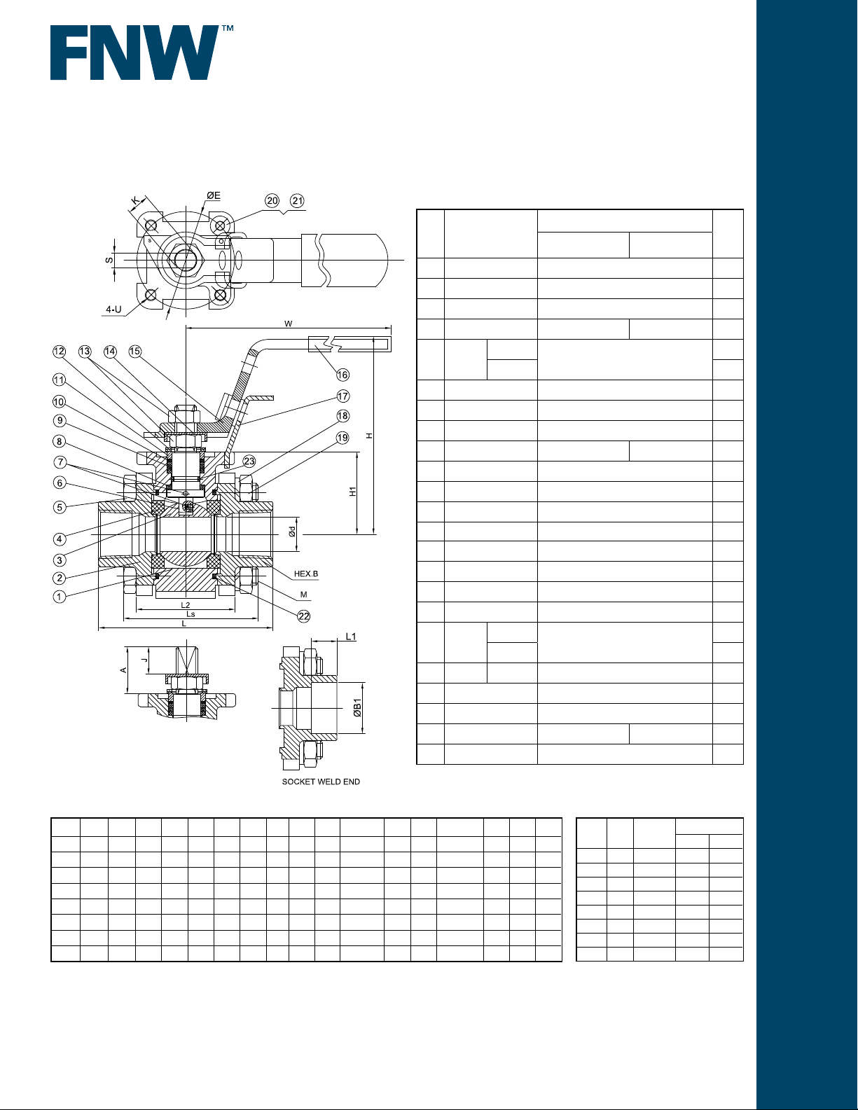
CARBON STEEL BALL VALVES
3 PC FULL PORT 2000 CWP
Standard Materials
Ref.
Description
No.
1 Body ASTM A216 Gr. WCB Carbon Steel 1
2 End Cap ASTM A216 Gr. WCB Carbon Steel 2
3 Ball 316SS Stainless 1
4 Seat TFM1600+20%GF TFM4215 2
Body
5
Bolt
6 Stem 316SS Stainless 1
7 Anti-Static Device 316SS Stainless 2
8 Thrust Washer TFM4215 1
9 V-Ring Packing PTFE TFM1600 1 Set
10 Bushing 50% Stainless + 50% PTFE 1
11 Gland 316SS Stainless 1
12 Belleville Washer 301SS Stainless 2
13 Stem Nut ASTM A194-8 Stainless 2
14 Stop-Lock-Cap 304SS Stainless 1
15 Handle 304SS Stainless 1
16 Handle Sleeve Vinyl Plastic 1
17 Lock Device 304SS Stainless 1
Bolt
18
Washer
19 Bolt Nut 1/4~1-1/4 ASTM A194-8 Stainless 4
20 Stop Bolt ASTM A193-B8 Stainless 1
21 Stop Washer 304SS Stainless 1
22 Body Gasket PTFE PTFE+20%CF 2
23 O-Ring FKM 1
1/4~1-1/4
1-1/2~2 8
1/4~1-1/4
1-1/2~2 8
Figure 321A Figure 321AC
ASTM A193-B8 Stainless
Figure 321A
Material
304SS Stainless
Qty
4
4
Dimensions (inches)
SIZE Ød L H1 H W ØE S U A J K (UNF) Ls L2 M (UNC) B L1 ØB1
1/4 0.42 2.76 1.18 2.99 5.31 1.65 0.25 M5 0.68 0.41 3/8-24 2.13 1.61 1/4-20 0.93 0.43 0.55
3/8 0.50 2.76 1.18 2.99 5.31 1.65 0.25 M5 0.68 0.41 3/8-24 2.13 1.61 1/4-20 0.93 0.43 0.69
1/2 0.59 2.95 1.42 3.27 5.31 1.65 0.25 M5 0.80 0.46 3/8-24 2.44 1.83 5/16-18 1.10 0.43 0.86
3/4 0.79 3.15 1.56 3.27 5.31 1.65 0.25 M5 0.80 0.46 3/8-24 2.74 2.05 3/8-16 1.34 0.51 1.07
1 0.98 3.54 1.79 3.86 6.69 1.97 0.35 M6 0.92 0.49 9/16-18 3.18 2.36 3/8-16 1.81 0.51 1.34
1-1/4 1.25 4.33 1.97 4.06 6.69 1.97 0.35 M6 0.92 0.49 9/16-18 3.86 2.76 1/2-13 2.17 0.51 1.68
1-1/2 1.50 4.72 2.36 4.33 7.87 2.76 0.38 M8 1.18 0.59 5/8-18 4.12 3.24 1/2-13 2.24 0.51 1.91
2 1.95 5.51 2.68 4.69 7.87 2.76 0.38 M8 1.18 0.59 5/8-18 4.90 3.68 5/8-11 2.87 0.63 2.41
DOC: FNW321A11 Ver. 06/2018
© 2018 - FNW. All rights reserved.
The FNW logo is a trademark of Ferguson Enterprises, Inc., PL Sourcing, PO Box 2778, Newport News, VA 23609
The contents of this publication are presented for information purposes only, and while effort has been made to ensure their accuracy, they are not to be construed as
warranties or guarantees, expressed or implied, regarding the products or services described herein or their use or applicability. All sales are governed by our terms and
conditions, which are available on request. We reserve the right to modify or improve the designs or specications of our products at any time without notice. Always
verify that you have the most recent product specications or other documentation prior to the installation of these products.
Cv, Torque & Weight
Size Cv
1/4 15 69 2.34 2.34
3/8 15 69 2.34 2.34
1/2 18 77 2.29 2.25
3/4 36 98 3.15 3.15
1 48 166 4.59 4.59
1-1/4 58 277 7.61 7.61
1-1/2 120 388 9.92 9.92
2 190 582 15.21 15.48
Torque
(in-lbs)
Wt (lbs)
NPT SW
 Loading...