

Page 1
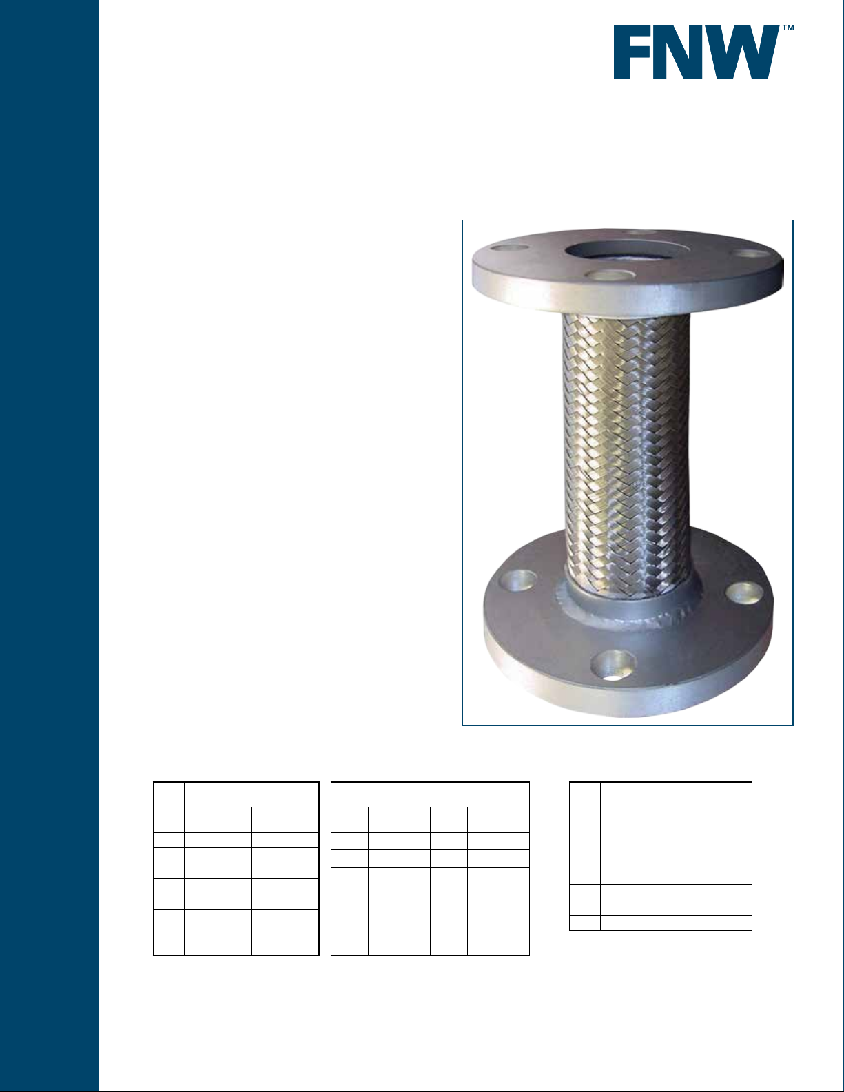
Figure 30F
* NOT RECOMMENDED FOR STEAM OR VACUUM SERVICE
FLEXIBLE CONNECTORS
FLANGED END METAL BRAIDED
FLEXIBLE CONNECTOR
Flexible connectors are used to absorb thermal and seismic movement,
absorb hydraulic shock, provide vibration and noise dampening, ease
installation and correct minor misalignment of piping and components.
They come in a variety of sizes, materials, and connection ends for
numerous applications.
The inner hose is an annular (bellows) design. An annular hose is better
suited for pump connections because it can better sustain torsion stress
due to longitudinal expansion from rises in pressure. Metal wire braid on a
hose assembly restrains against hose elongation under higher pressures
and acts to dampen vibration. A heavy braid also increases abrasion
resistance. Optimal braid coverage will contain the core under pressure
and reduce the possibility of twisting and squirming.
The use of braided metal connectors for applications such as pumps,
compressors and other mechanical equipment can enhance the overall
operation of a system.
Braided connectors have the advantages of:
• Longer service life
• Increased pressure capacity
• Greater fatigue resistance due to ex
• Increased temperature capacity of media
• Greater protection of annular hose
• Acceptance of thermal expansion
Pressure / Temperature
Pressure @ 70°F
Size
Working PSI Test PSI
2 455 683
2-1/2 345 518
3 290 435
4 250 375
5 200 300
6 210 315
8 190 285
10 150 225
* Multiply working pressure by pressure factor for temperature adjusted pressure rating.
Pressure Factors for Above 70°F*
°F Factor °F Factor
100 0.99 450 0.81
150 0.96 500 0.79
200 0.94 550 0.76
250 0.92 600 0.74
300 0.89 650 0.72
350 0.86 800 0.66
400 0.84 1000 0.60
www.fnw.com
Part Numbers & Weight
Size Part Number
2 FNW30FK 12
2-1/2 FNW30FL 13
3 FNW30FM 14
4 FNW30FP 19
5 FNW30FS 27
6 FNW30FU 32
8 FNW30Fx 50
10 FNW30F10 76
Approx. Wt
(Lbs)
Page 2
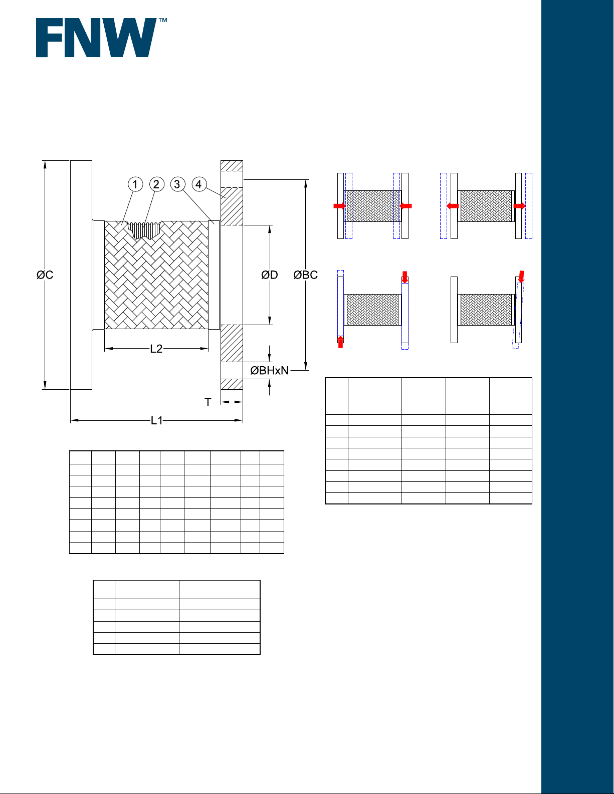
Figure 30F
FLEXIBLE CONNECTORS
FLANGED END METAL BRAIDED
FLEXIBLE CONNECTOR
Braid Limits
Dimensions (inches)
Size ØC ØD L1 L2 ØBC ØBH N T
2 6.0 2.44 9 5.78 4.75 0.75 4 0.62
2-1/2 7.0 2.94 9 5.78 5.50 0.75 4 0.62
3 7.5 3.57 9 5.78 6.00 0.75 4 0.62
4 9.0 4.57 9 5.39 7.50 0.75 8 0.62
5 10.0 5.66 11 7.14 8.50 0.87 8 0.75
6 11.0 6.72 11 6.74 9.50 0.87 8 0.75
8 13.5 8.72 12 7.24 11.75 0.87 8 1.00
10 16.0 10.88 13 7.85 14.25 1.00 12 1.00
Axial Compression
Transverse Movement
Maximum
Size
2 0.16” 0.16” ±0.12” 1.5°
2-1/2 0.16” 0.16” ±0.12” 1.5°
3 0.16” 0.16” ±0.12” 1.5°
4 0.16” 0.16” ±0.12” 1.5°
5 0.20” 0.20” ±0.16” 1°
6 0.20” 0.20” ±0.16” 1°
8 0.20” 0.20” ±0.16” 1°
10 0.20” 0.20” ±0.16” 1°
Axial
Compression
Maximum
Axial
Elongation
Axial Elongation
Angular Deection
Maximum
Transverse
Movement
Maximum
Angular
Deection
Standard Materials
Ref.
Description Material
No.
1 Hose Braid 304 Stainless Steel
2 Corrugated Hose 321 Stainless Steel
3 Braid Band 304 Stainless Steel
4 Flange Carbon Steel
5 Welding Grade er308 Stainless
DOC: FNW30F05 Ver. 6/2018
© 2018 - FNW. All rights reserved.
The FNW logo is a trademark of Ferguson Enterprises, Inc., PL Sourcing, PO Box 2778, Newport News, VA 23609
The contents of this publication are presented for information purposes only, and while effort has been made to ensure their accuracy, they are not to be construed as
warranties or guarantees, expressed or implied, regarding the products or services described herein or their use or applicability. All sales are governed by our terms and
conditions, which are available on request. We reserve the right to modify or improve the designs or specications of our products at any time without notice. Always
verify that you have the most recent product specications or other documentation prior to the installation of these products.
 Loading...