

Page 1

Figure 2020
KNIFE GATE VALVES
STAINLESS STEEL BIDIRECTIONAL
RESILIENT SEATED KNIFE GATE VALVE
steel body and yoke with investment cast packing follower.
that utilize a retaining ring to secure the seat, the dual seat,
performs in many applications not typical of knife gate valves.
Features
• Bidirectional Shut-off
• Maximum Pressure: 150 PSI CWP
• Maximum Temperature: 248°F (120°C)
• Cast Stainless Steel Body, Yoke, & Packing Gland
• Thrust Needle Bearings
•
Minimum Line Pressure
• Elastomer Quad Seal is Standard in Packing Arrangement
• Stainless Steel Position Indication Arrow
• Adjustable Close Stop
• Stainless Steel Hardware
• Machined Gland Pocket Area
• Bonnetless, Outside Screw & Yoke
• Rising Stem
• Cast Iron Hand Wheel
• Available in sizes 2” to 24”
• Standard design accommodates locking device
Standards
• Face-to-Face: MSS SP-81
• Flange Drilling: ANSI B16.5
• Testing:
○ Shell (Before Assembly): 1.5 Time Max. CWP (No Leak)
○ Seat: 1.1 Times Max. CWP (No Leak)
• Material: ASME B16.34
Figure Number Matrix
FNW 2020 Seat Size
SEAT CODE
RTFE = T
2 = K
2-1/2 = L
3 = M
4 = P
6 = U
SIZE CODE
8 = X
10 = 10
12 = 12
14 = 14
16 = 16
Cv & Weight
Size Cv Wt (Lbs)
2 240 37
2-1/2 565 40
3 565 44
4 1,040 53
6 2,440 88
8 4,460 139
10 6,250 181
Size Cv Wt (Lbs)
12 9,400 229
14 12,500 364
16 16,500 397
18 21,400 463
20 27,000 573
24 39,700 617
Weights are for general reference only.
18 = 18
20 = 20
24 = 24
Repair Kits (Order Separately)
FNW 2020 Kit Size
SEAT CODE
Repair Kit = RK
Contains two seats / two o-rings
2 = K
2-1/2 = L
3 = M
4 = P
6 = U
SIZE CODE
8 = X
10 = 10
12 = 12
14 = 14
16 = 16
18 = 18
20 = 20
24 = 24
www.fnw.com
Page 2
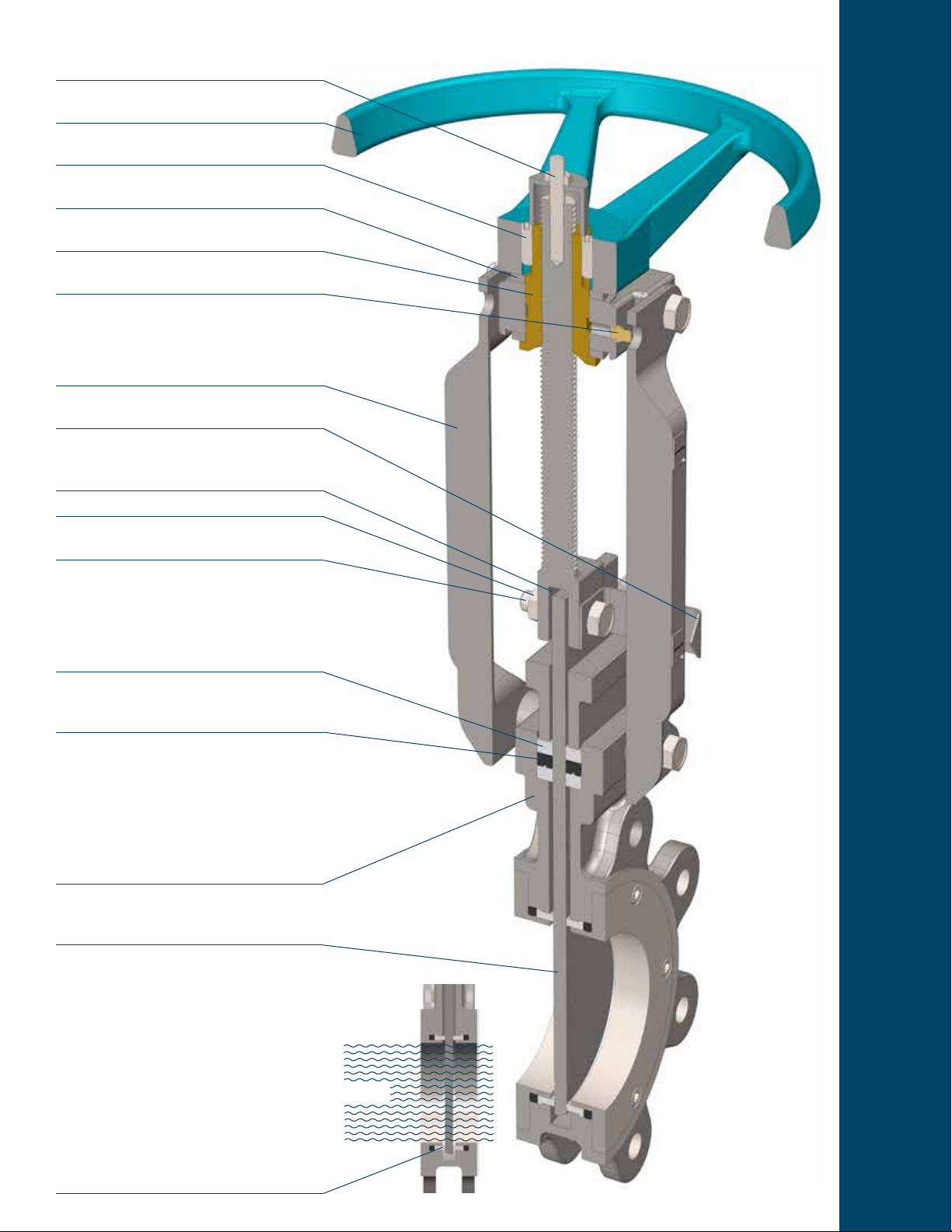
An adjustable stopper at the top of the stem sets
the close position of the gate.
Hand wheel is heavy cast iron, with a rounded grip
and epoxy coated hand wheel.
Double set screws prevent threaded-on hand
wheel from backing off or coming loose.
Stainless steel needle bearings reduce hand wheel
rim pull force.
Aluminum-Bronze thrust components for antigalling operation.
Grease tting for maintaining smooth drive sleeve
operation.
Cast stainless steel yoke arms provide optimum
exural rigidity.
Stainless steel position indication arrow is
standard
Stem-to-gate clevis is deliberately loose to allow
play in gate to minimize binding.
Stainless steel hardware is standard.
Horizontal clevis bolts provide exibility of the gate
during travel.
FEATURES
Multiple layers of PTFE impregnated square braid
packing provides excellent gland sealing at full
valve pressure differential.
Elastomer quad seal improves packing
performance by promoting live loading of the
packing.
The single piece cast all stainless steel body is
rugged and compact. It offers better leak tightness
than fabricated or two-piece designs.
The gate is high-quality, ground-nished stainless
steel. A generous gate thickness is well supported
by the packing.
The unique retainer, o-ring, seat assembly
provides positive shut-off at minimum pressure
differential. Securing the seats out of the ow path
improves the longevity of the resilient material;
however, this conguration also allows easy
replacement of the seat and o-ring.
FLOW
Page 3

Seat Seal Conguration
The gure 2020 utilizes a seating design that provides positive shut-off in both
directions, even at low pressure differentials. Similar to high performance buttery
valve designs, the 2020 uses mechanically held retainer rings to hold the seat in
place.
The RTFE seats are secured with an integral locator lip. Seats are energized with
hefty EPDM o-rings to provide sealing pressure against the gate. The o-rings also
act as the seal between the body and seat. Both are secured with stainless steel
retainer rings and screws.
Seats and o-rings can easily be replaced without disturbing the valve packing. This
conguration also impoves the longevity of the seats because they are not directly
in the ow path.
Standard Materials
Retainer Ring
Retainer Screws
Ref.
Description Material Qty
No.
1 Body
1A Seat RTFE 2
1B Seat O-ring EPDM 2
1C
1D
10 Yoke Bolt
11 Stem
12 Clevis Bolt
13 Clevis Nut
14 Collar
15 Collar Bolt
16 Collar Nut
17 Hand Wheel Cast Iron, ASTM A126 Gr. B 1
18 Yoke Sleeve
19
20 Set Screws Stainless Steel, 304SS 2
21
23 Stopper Stud
24 Stopper
25 Stopper Nut
Seat
Retainer
Ring
Retainer
Screws
2 Gate
3 Packing
4 Quad Seal EPDM 1
6 Gland
7 Gland Bolt
8 Gland Nut
9 Yoke Arm
Thrust
Needle
Bearing
Position
Indicator
Stainless Steel, ASTM A351
Stainless Steel, ASTM A351
Stainless Steel, ASTM A240
PTFE Impregnated Syntex
Stainless Steel, ASTM A351
Stainless Steel, ASTM A351
Stainless Steel, ASTM A276
Stainless Steel, ASTM A351
ASTM B148, UNS C95200
Stainless Steel, ASTM A276
RTFE Seat
EPDM O-ring
Gr. CF8M
Gr. CF8M
Stainless Steel 316,
ASTM A193 Gr. B8M
Type 316
2 (2”~18”)
Fiber
Gr.CF8M
Stainless Steel 304,
ASTM A193 Gr. B8
Stainless Steel 304,
ASTM A194 Gr. 8
Gr.CF8
Stainless Steel 304,
ASTM A193 Gr. B8
Type 304
Stainless Steel 304,
ASTM A193 Gr. B8
Stainless Steel 304,
ASTM A194 Gr. 8
Gr.CF8
Stainless Steel 304,
ASTM A193 Gr. B8
Stainless Steel 304,
ASTM A194 Gr. 8
Aluminum Bronze,
Stainless Steel, 2
Stainless Steel, 304SS 1
Stainless Steel 304,
ASTM A193 Gr. B8
Type 304
Stainless Steel 304,
ASTM A194 Gr. 8
3 (20”~24”)
2 (2”~8”)
4 (10”~24”)
2 (2”~8”)
1
2
2 Sets
1
1
2~10
2~10
2
4
1
2
2
1
1
1
1
1
Page 4

Figure 2020
KNIFE GATE VALVES
STAINLESS STEEL BIDIRECTIONAL
RESILIENT SEATED KNIFE GATE VALVE
Dimensions (inches)
Size A B C D E F G H J K N S
2 1.88 4.75 3.62 13.98 16.26 10.00 2 5/8”-11 0.35 2 1.83 0.50
2-1/2 2.00 5.50 5.00 15.83 19.53 10.00 2 5/8”-11 0.39 2 2.74 0.50
3 2.00 6.00 5.00 15.83 19.53 10.00 2 5/8”-11 0.39 2 2.74 0.50
4 2.00 7.50 6.19 17.95 22.36 10.00 2 5/8”-11 0.39 6 3.72 0.50
6 2.25 9.50 8.50 21.81 28.19 11.75 2 3/4”-10 0.43 6 5.69 0.63
8 2.75 11.75 10.62 26.38 34.57 16.00 2 3/4”-10 0.43 6 7.46 0.63
10 2.75 14.25 12.75 30.91 41.14 16.00 4 7/8”-9 0.49 8 9.43 0.75
12 3.00 17.00 15.00 35.12 47.17 20.00 4 7/8”-9 0.43 8 11.40 0.75
14 3.00 18.75 16.25 39.17 52.95 20.00 4 1”-8 0.51 8 12.97 0.81
16 3.50 21.25 18.50 41.73 58.27 20.00 6 1”-8 0.55 10 14.55 0.88
18 3.50 22.75 21.00 47.24 64.57 20.00 6 1-1/8”-7 0.59 10 16.52 0.94
20 4.50 25.00 23.00 52.44 71.65 20.00 8 1-1/8”-7 0.75 12 18.48 1.00
24 4.50 29.50 27.25 61.18 84.25 20.00 8 1-1/4”-7 0.91 12 22.42 1.00
DOC: FNW202017 Ver. 7/2017
© 2017 - FNW. All rights reserved. 22038
The FNW logo is a trademark of Ferguson Enterprises, Inc., PL Sourcing, PO Box 2778, Newport News, VA 23609
The contents of this publication are presented for information purposes only, and while effort has been made to ensure their accuracy, they are not to be construed as
warranties or guarantees, expressed or implied, regarding the products or services described herein or their use or applicability. All sales are governed by our terms and
conditions, which are available on request. We reserve the right to modify or improve the designs or specications of our products at any time without notice. Always
verify that you have the most recent product specications or other documentation prior to the installation of these products.
 Loading...